

Page 1
Repair
™
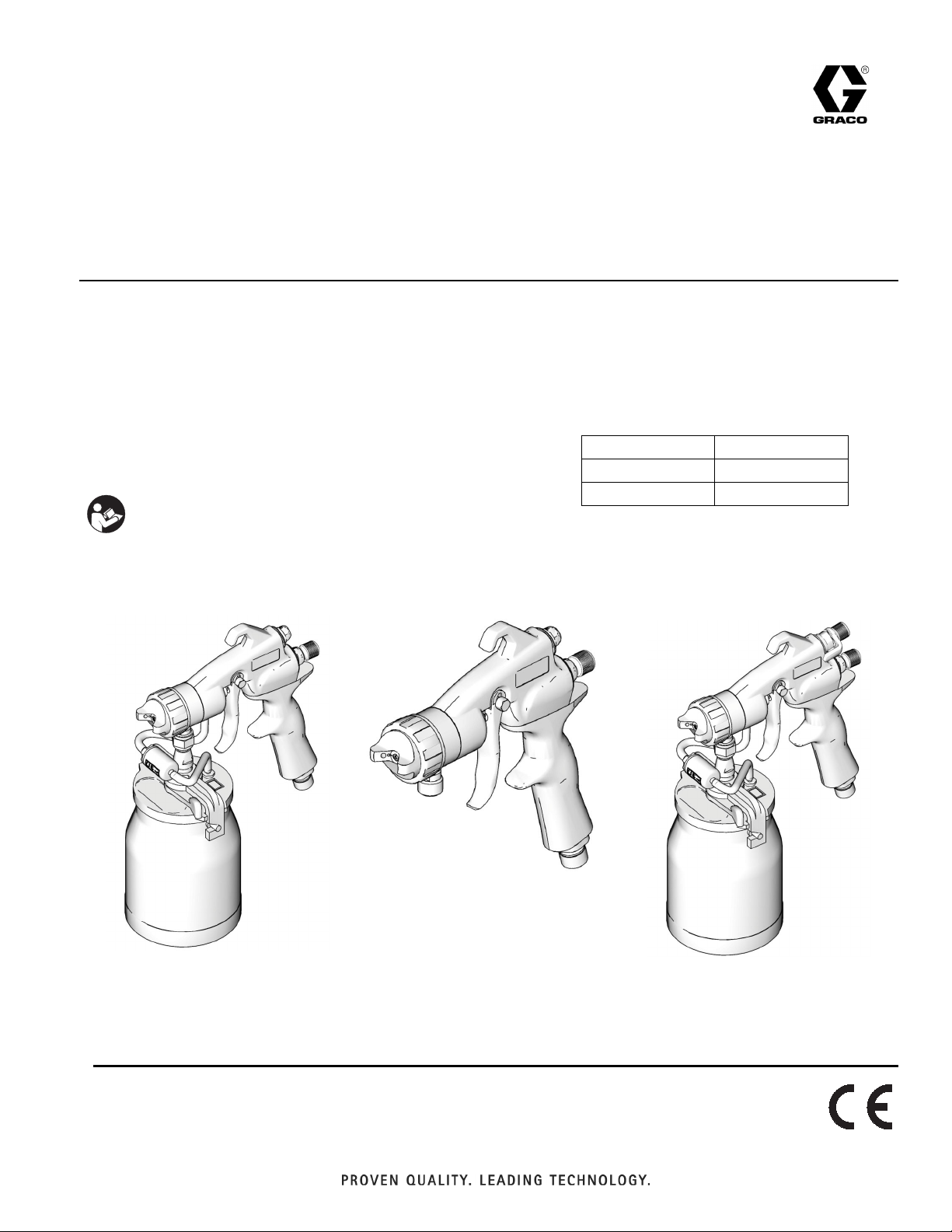
HVLP EDGE
- For the application of architectural paints and coatings. The HVLP Edge gun is not
intended to be used on an external compressor. -
Models: 256855, 257092, 256856
Maximum Fluid Working Pressure: 50 psi (0.35 MPa, 3.5 bar)
Maximum Air Working Pressure: 10 psi (0.07 MPa, 0.7 bar)
Important Safety Instructions
Refer to your sprayer instruction manual for
Pressure Relief and spray instructions.
Keep these instructions.
Gun
Translated Manuals
English - 313317 Spanish - 313339
French - 313325 Korean - 313617
Chinese - 313618
313317H
EN
Registered Design No. 001147813-0001
ti12761a
256855
257092
ti12761a
ti12870a
256856
Page 2
Warnings
Warnings
The following Warnings are for the setup, use, grounding, maintenance and repair of this equipment. The exclamation point symbol
alerts you to a general warning and hazard symbols refer to procedure-specific risks. Refer back to these Warnings. Additional, prod-
uct-specific warnings may be found throughout the body of this manual where applicable.
WARNING
FIRE AND EXPLOSION HAZARD
Flammable fumes, such as solvent and paint fumes, in work area can ignite or explode. To help prevent fire and explosion:
• Use equipment only in well ventilated area.
• Eliminate all ignition sources; such as pilot lights, cigarettes, portable electric lamps, and plastic drop cloths
(potential static arc).
• Keep work area free of debris, including solvent, rags and gasoline.
• Do not plug or unplug power cords, or turn power or light switches on or off when flammable fumes are present.
• Ground all equipment in the work area. See Grounding instructions.
• Use only grounded hoses.
• Hold gun firmly to side of grounded pail when triggering into pail. Do not use pail liners unless they are antistatic or
conductive.
• Stop operation immediately if static sparking occurs or you feel a shock. Do not use equipment until you identify
and correct the problem.
• Keep a working fire extinguisher in the work area.
• When flammable liquid is sprayed or used for flushing or cleaning, keep sprayer at least 20 feet (6 meters) away
from explosive vapors.
• Do not clean with materials having flash points lower than 70° F (21° C). Use water-based materials or mineral
spirits-type material only. For complete information about your fluid, request the MSDS from the fluid distributor or
retailer.
EQUIPMENT MISUSE HAZARD
Misuse can cause death or serious injury.
• Do not operate the unit when fatigued or under the influence of drugs or alcohol.
• Do not exceed the maximum working pressure or temperature rating of the lowest rated system component. See
Technical Data in all equipment manuals.
• Use fluids and solvents that are compatible with equipment wetted parts. See Technical Data in all equipment
manuals. Read fluid and solvent manufacturer’s warnings. For complete information about your material, request
MSDS from distributor or retailer.
• Check equipment daily. Repair or replace worn or damaged parts immediately with genuine manufacturer’s
replacement parts only.
• Do not alter or modify equipment. Alterations or modifications may void agency approvals and create safety hazards.
• Make sure all equipment is rated and approved for the environment in which you are using it.
• Use equipment only for its intended purpose. Call your distributor for information.
• Route hoses and cables away from traffic areas, sharp edges, moving parts, and hot surfaces.
• Do not kink or over bend hoses or use hoses to pull equipment.
• Keep children and animals away from work area.
• Comply with all applicable safety regulations.
PRESSURIZED ALUMINUM PARTS HAZARD
Use of fluids that are incompatible with aluminum in pressurized equipment can cause serious chemical reaction and
equipment rupture. Failure to follow this warning can result in death, serious injury, or property damage.
• Do not use 1,1,1-trichloroethane, methylene chloride, other halogenated hydrocarbon solvents or fluids containing
such solvents.
• Many other fluids may contain chemicals that can react with aluminum. Contact your material supplier for compatibility.
PERSONAL PROTECTIVE EQUIPMENT
Wear appropriate protective equipment when in the work area to help prevent serious injury, including eye injury, hearing loss, inhalation of toxic fumes, and burns. This protective equipment includes but is not limited to:
• Protective eyewear, and hearing protection.
• Respirators, protective clothing, and gloves as recommended by the fluid and solvent manufacturer
2 313317H
Page 3

Warnings
WARNING
CALIFORNIA PROPOSITION 65
The engine exhaust from this product contains a chemical known to the State of California to cause
cancer, birth defects or other reproductive harm.
313317H 3
Page 4
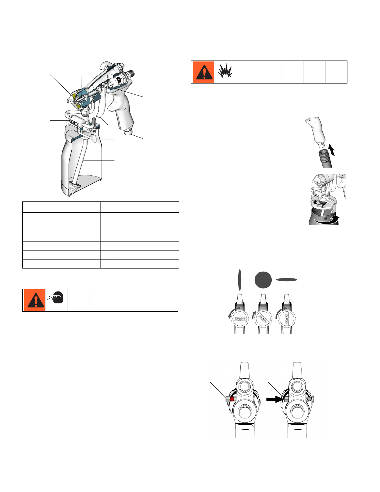
Component Identification
Component Identification
DE F
C
B
J
K
A
M
N
ID Component ID Component
A Siphon Cup G Trigger Slide
B Check Valve H Air Inlet
C Air Cap J
EasyGlide
D Air Nozzle K Latch
E Fluid Needle M Swivel Tube
F Flow Control Knob N Strainer
G
H
ti12771a
™
Trigger
Setup
Make sure sprayer is turned off and unplugged from
power source. Refer to your sprayer instruction manual
for spray setup.
Connect Gun to Siphon Cup
1. Attach air hose from sprayer to
inlet fitting of gun.
ti12797a
2. Fill cup 3/4 full. Install cover. Latch
the gun cup cover to secure it to
siphon cup.
ti12872a
Operation
Adjust Spray Pattern
1. Set air cap to position for spray pattern desired.
Pressure Relief Procedure
The spray gun cup is pressurized by the gun air supply.
To reduce the risk of serious injury from pressurized fluid
or accidental spray from gun, always turn off the air supply to the gun before removing the spray gun cup. Unplug
sprayer from outlet
ti12763a
2. Verify trigger slide is in SPRAY position (E) and not
NEEDLE REMOVAL position (D).
ED
ti12795a
4 313317H
Page 5
Adjust Flow and Pattern Size
Flow and pattern size is determined by the flow control
knob. Set knob at 0. Increase flow to attain desired spray
pattern.
Operation
2. Pour small amount of solvent or
water recommended by spray
material manufacturer into siphon
cup.
ti12775a
3. Latch the gun cup cover to secure
it to siphon cup.
ti12772a
ti12823a
Spray
1. Keep gun perpendicular to surface and at a distance
of 6 to 8 in. (150 to 200 mm) from surface.
2. Have spray gun in motion before triggering. Move
spray gun in a straight, smooth stroke. Release
trigger at end of stroke.
6 to 8 in. (150 to 200 mm)
RIGHT
WRONG
ti12793a
Cleaning Spray Gun
Before cleaning gun, read all warnings and do Pressure
Relief Procedure.
1. Remove siphon cup. Empty spray
material from siphon cup.
4. Swirl solvent or water inside of gun.
5. Spray solvent or water into waste
pail until spray appears to be clean.
6. Remove siphon cup. Empty
remaining solvent or water from
siphon cup.
7. Clean inside of siphon cup with a
clean rag.
8. Remove retaining ring, air cap
and fluid nozzle. Clean in solvent
or water. Clean face of gun with a
solvent or water dampened rag.
ti12872a
ti12906
ti12905a
ti12778a
9. Assemble gun. Wipe gun with
solvent or water dampened rag.
ti12775a
ti12780a
313317H 5
Page 6

Operation
Check Valve Troubleshooting
Recommended if fluid is in the check valve.
Poppet Valve Quick Clear
1. Disconnect check valve from
siphon cup air hoses.
ti13104a
2. Unscrew check valve.
ti13105a
3. Pull out on nub on poppet
valve and release.
ti13106a
4. Assemble check valve. Install
on air hoses.
5. Try spraying again to see if
spraying is normal.
Check Valve Cleaning
Needle Replacement
Removal
1. Relieve pressure.
2. Remove air cap (1).
3. Push trigger slide (4) over to NEEDLE REMOVAL
position (D) shown in Component Identification, page
4.
4. Remove fluid nozzle (2).
5. Pull needle (3) out.
Installation
1. Insert needle (3).
2. Install fluid nozzle (2).
3. Push trigger slide (4) over to SPRAY position (E)
shown in Component Identification, page 4.
4. Install air cap.
6
1. Do steps 1 and 2 of Poppet Valve Quick Clean.
2. Unscrew poppet valve from
check valve.
3. Clean all parts in solvent recommended by spray material
ti13107a
manufacturer.
4. After all parts are dry apply a light coat of petroleum
jelly all over o-ring.
5. Assemble check valve. Install on air hoses.
1
4
3
2
5
ti12766a
6 313317H
Page 7

Seal Replacement and Adjustment Procedure
Operation
1. Remove air cap ring (10) and air cap housing (9)
2. Slide trigger pin (14) over to needle removal position.
Lower trigger (13) to disengage needle.
3. Remove fluid nozzle (44)
4. Remove needle (44). Check fluid needle for damage
or wear.
5. Remove housing nut (7) and remove housing (3)
from gun body
6. Remove packing nut (8d), spacer (8c), packing (8b),
and spreader (8a) from housing (3).
7. Install new spreader (8a) and packing (8b) in housing
(3). Note orientation of spreader and packing.
8. Install spacer (8c).
9. Install packing nut (8d) but don’t tighten until needle
(44) is installed.
10. Install housing (3) into gun body and secure with nut
(7).
11. Lubricate and install needle and fluid nozzle (44)
12. Raise trigger (13) to engage needle
13. Tighten packing nut (8d)
14. Trigger gun to test needle movement. If needle does
not return after trigger is released or is slow to return,
loosen packing nut slightly until needle returns freely.
15. Make sure gun fluid packing’s are sealing properly by
spraying solvent.
16. If fluid packings leak, tighten packing screw slightly
and re-test until packing’s seal completely.
10
14
1
44
needle
9
3
21
8a
13
8d
8c
8b
8
32
2
15
7
ti19030a
313317H 7
Page 8

Material Fluid Set #2
Dye
Ink
Non-Wiping Stain
Automotive Finish
Lacquer
Stain
Enamel
Epoxy
Urethane
Varnish
Primer
Industrial Finishes
Latex
Multi-Spec
Butyrate
Nitrate Dope
Oil Wall Paint
256946
Material / Fluid Set Selection Guide
Fluid Set #3
256947
Fluid Set #4
256948
Fluid Set #5
256949
Fluid Set #6
256950
Operation
Selecting Fluid Sets:
Grooves at end of fluid needle indicate
size of fluid set. Example: Needle with 2
grooves on end goes with #2 fluid set.
#2
ti13753a
Swivel Tube Adjustment
The adjustable swivel tube allows the gun to be held in
any position while spraying.
To adjust the position of the tube in the cup:
1. Loose nut (F). Rotate cup to desired spray position.
2. Tighten nut (F).
F
ti12776a
ti12777a
Optional Artisan Air Valve (256927)
Installation
1. Remove air plug housing.
2. Install Artisan air valve.
ti12910a
8 313317H
Page 9

Troubleshooting
Problem Cause Solution
Orange peel finish - Paint
surface not smooth
Blushing - clear coatings
appear milky
Fish eyes - small pools on
painted surface that will not
fill
Runs and sags Applying too much paint per pass for
Solvent pops or bubbles Sprayed surface drying before sol-
Pain droplets too large • Maintain proper spraying distance, page 5.
Paint droplets drying too fast to properly flow out of gun
Cold weather spraying Keep fluid and object being sprayed as close to
Moisture condensation is trapped in
lacquer when spraying in hot, humid
conditions
Silicone contamination from lubricants, grease, polish, or waxes on
the surface being sprayed
the drying conditions
vent gas can be released
Troubleshooting
• Keep turbine air filters clean to allow full air
flow.
• Do not use an air hose that is too long to
provide sufficient atomization pressure.
• If droplets are still too large, reduce fluid.
Keep object being sprayed out of direct sunlight.
When spraying in warmer temperatures, use a
slower evaporating solvent or a reducer.
room temperature as possible. When spraying
on a cold surface, most paints will become too
thick to flow properly.
• Allow turbine to warm up a few minutes
before spraying.
• Store lacquer off concrete floors, at room
temperature.
• Apply lighter coats and allow for proper drying time.
• Use a slower evaporating solvent or
reducer.
• Do not spray in windy conditions.
Clean all parts with a cleaning solvent; wipe with
a solvent rag and a clean rag. Replace rags as
needed. If problem persists, use a fish eye eliminator.
• Move gun faster or decrease fluid flow.
• Maintain proper spraying distance, page 5.
• Reduce amount of thinner or use a faster
drying thinner.
• Apply fluid in lighter coats to allow for proper
evaporation.
• Use the recommended thinners.
• Follow the solutions for Orange Peel Finish,
Paint Droplets Too Large in this Troubleshooting Table.
313317H 9
Page 10

Problem Cause Solution
No or slow fluid flow, intermit-
Wrong size fluid set being used Select proper fluid set for fluid being sprayed,
tent spray, or fluttering spray
Gun fluid nozzle blocked by dried
paint or damaged
Cup or pressure pot cover not tight
enough or gasket damaged
Cup or pressure pot fluid tubes
blocked by dried paint or damaged
Air flow to cup blocked To check, remove cup (leave cover connected).
Needle packings not properly
adjusted.
Note: Fluid loss through packings
affects fluid pressure and causes a
fluid leak from gun body.
Plugged inlet strainer Replace strainer if plugged or remove strainer if
Fluid leaks at fluid nozzle
Needle not seating in fluid nozzle Check for a loose fluid nozzle or a bent nozzle
after trigger is released
Poor spray pattern Air cap horn hole and/or fluid nozzle
plugged
Troubleshooting
page 6
Clean or replace fluid nozzle
Tighten cover or replace gasket
Clean or replace fluid tubes
Trigger gun and check air flow out of check
valve. If air is not flowing freely, clean or replace
check valve.
Clean gun body with solvent and brush provided. Adjust needle packings.
material is high viscous.
or needle; tighten nozzle or replace parts as
needed.
Soak air cap and/or fluid nozzle in solvent.
Clean air cap horn holes with non-metallic item
to avoid permanently damaging them.
10 313317H
Page 11

Parts
Parts
10
21
22
22a
37
22b
9
44
3
8a
8
8b
29
8c
15
45
49
8d
29a
29b
29c
7
29d
23
14
1
13
32
2
12
19
17
24
Ref Part Description Qty
1 256858 BODY, gun 1
2 188493 PACKING, u-cup, gun 1
3 257108 HOUSING, nozzle 1
7 192348 NUT, head 1
8 256960 KIT, includes 8a, 8b, 8c, 8d 1
8a SPREADER, u-cup 1
8b PACKING, u-cup 1
8c SPACER, packing 1
8d NUT, head 1
9 256951 HOUSING, air, cap 1
10 256861 RING, retaining, cap, air 1
12 257087 VALVE, air 1
13 15V846 TRIGGER 1
14 280545 PIN, slide, trigger, w/ball 1
15 15V848 NUT, slide, trigger, pin 1
17 257086 VALVE, fluid 1
19 114069 SPRING, compression 1
21 196468 FITTING, adapter 1
22 244130 CUP, 1qt, under (includes 22a, 22b) 1
22a M70424 CUP, gasket 1
25
ti12764b
Ref Part Description Qty
22b 244132 CUP, bottom 1
23 196463 TUBE, handle 1
24 277950 HANDLE, gun 1
25 196464 COUPLER, male 1
29 256957 CHECK VALVE, complete, includes
29a, 29b*, 29c, 29d
29a FITTING, adapter 1
29b* POPPET, check valve assembly 1
29c FITTING, air 1
29d TUBE, air, cup 2
32 15V844 HOUSING, plug, fluid 1
37 193218 STRAINER 1
44 See Material / Fluid Set Selection
Guide table, page 6,
45 M70394 STEM, air pressure 1
49 M71149 SCREW, set, sch 1
Replacement Danger and Warning labels, tags, and cards
are available at no cost.
* Three-pack Check Valve Repair Kit 256956 is available
1
313317H 11
Page 12

Technical Data
Maximum inlet fluid pressure 50 psi (0.35 MPa, 3.5 bar)
Maximum inlet air pressure 10 psi (0.07 MPa, 0.7 bar)
Air inlet Quick-disconnect
Fluid inlet 3/8 nps
Sound levels per ISO 3744
Sound power level less than 65.0 dB(A)
Sound pressure level less than 65.0 dB(A)
Wetted parts
Bare spray gun stainless steel, aluminum
Spray gun cups aluminum, polyethylene
1-quart optional remote cup aluminum, polyethylene
Technical Data
12 313317H
Page 13

Notes
Notes
313317H 13
Page 14

Graco Standard Warranty
Graco warrants all equipment referenced in this document which is manufactured by Graco and bearing its name to be free from defects in
material and workmanship on the date of sale to the original purchaser for use. With the exception of any special, extended, or limited warranty
published by Graco, Graco will, for a period of twelve months from the date of sale, repair or replace any part of the equipment determined by
Graco to be defective. This warranty applies only when the equipment is installed, operated and maintained in accordance with Graco’s written
recommendations.
This warranty does not cover, and Graco shall not be liable for general wear and tear, or any malfunction, damage or wear caused by faulty
installation, misapplication, abrasion, corrosion, inadequate or improper maintenance, negligence, accident, tampering, or substitution of
non-Graco component parts. Nor shall Graco be liable for malfunction, damage or wear caused by the incompatibility of Graco equipment with
structures, accessories, equipment or materials not supplied by Graco, or the improper design, manufacture, installation, operation or maintenance
of structures, accessories, equipment or materials not supplied by Graco.
This warranty is conditioned upon the prepaid return of the equipment claimed to be defective to an authorized Graco distributor for verification of
the claimed defect. If the claimed defect is verified, Graco will repair or replace free of charge any defective parts. The equipment will be returned
to the original purchaser transportation prepaid. If inspection of the equipment does not disclose any defect in material or workmanship, repairs will
be made at a reasonable charge, which charges may include the costs of parts, labor, and transportation.
THIS WARRANTY IS EXCLUSIVE, AND IS IN LIEU OF ANY OTHER WARRANTIES, EXPRESS OR IMPLIED, INCLUDING BUT NOT LIMITED
TO WARRANTY OF MERCHANTABILITY OR WARRANTY OF FITNESS FOR A PARTICULAR PURPOSE.
Graco’s sole obligation and buyer’s sole remedy for any breach of warranty shall be as set forth above. The buyer agrees that no other remedy
(including, but not limited to, incidental or consequential damages for lost profits, lost sales, injury to person or property, or any other incidental or
consequential loss) shall be available. Any action for breach of warranty must be brought within two (2) years of the date of sale.
GRACO MAKES NO WARRANTY, AND DISCLAIMS ALL IMPLIED WARRANTIES OF MERCHANTABILITY AND FITNESS FOR A
PARTICULAR PURPOSE, IN CONNECTION WITH ACCESSORIES, EQUIPMENT, MATERIALS OR COMPONENTS SOLD BUT NOT
MANUFACTURED BY GRACO. These items sold, but not manufactured by Graco (such as electric motors, switches, hose, etc.), are subject to
the warranty, if any, of their manufacturer. Graco will provide purchaser with reasonable assistance in making any claim for breach of these
warranties.
In no event will Graco be liable for indirect, incidental, special or consequential damages resulting from Graco supplying equipment hereunder, or
the furnishing, performance, or use of any products or other goods sold hereto, whether due to a breach of contract, breach of warranty, the
negligence of Graco, or otherwise.
FOR GRACO CANADA CUSTOMERS
The Parties acknowledge that they have required that the present document, as well as all documents, notices and legal proceedings entered into,
given or instituted pursuant hereto or relating directly or indirectly hereto, be drawn up in English. Les parties reconnaissent avoir convenu que la
rédaction du présente document sera en Anglais, ainsi que tous documents, avis et procédures judiciaires exécutés, donnés ou intentés, à la suite
de ou en rapport, directement ou indirectement, avec les procédures concernées.
Graco Information
For the latest information about Graco products, visit www.graco.com.
TO PLACE AN ORDER, contact your Graco distributor or call 1-800-690-2894 to identify the nearest distributor.
All written and visual data contained in this document reflects the latest product information available at the time of publication.
GRACO INC. AND SUBSIDIARIES • P.O. BOX 1441 • MINNEAPOLIS MN 55440-1441 • USA
Copyright 2008, Graco Inc. All Graco manufacturing locations are registered to ISO 9001.
Graco reserves the right to make changes at any time without notice.
For patent information, see www.graco.com/patents.
Original instructions. This manual contains English. MM 313317
Graco Headquarters: Minneapolis
International Offices: Belgium, China, Japan, Korea
www.graco.com
Revised Novemeber 2013
 Loading...