

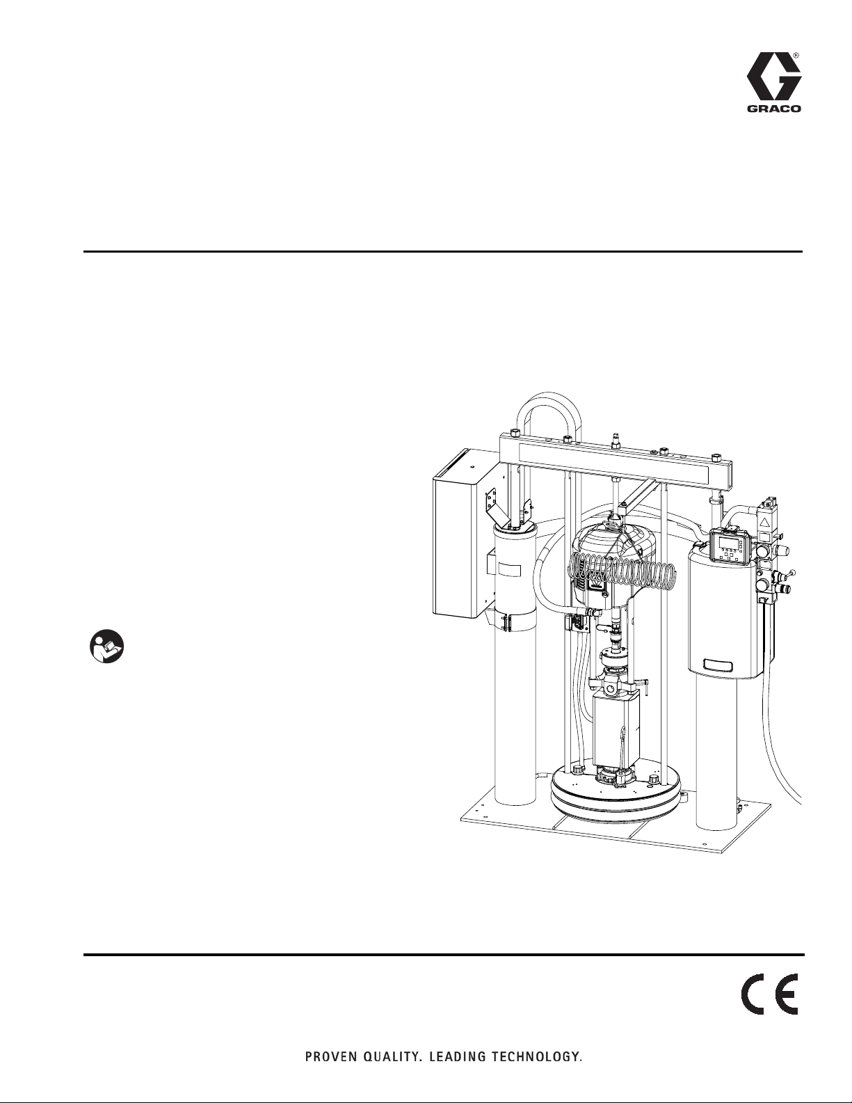
Page 1
Instructions - Parts
Warm Melt Supply
313296J
Systems
For use with heated bulk supply of medium to high viscosity sealant and adhesive
materials. Not for use in hazardous locations. Intended for indoor use only.
D60 3 inch dual post
60 liter (16 gallon), 30 liter (8 gallon), and
20 liter (5 gallon) sizes
150 psi (1.0 MPa, 10 bar) Maximum Air Inlet Pressure
D200 3 inch dual post
200 liter (55 gallon)
150 psi (1.0 MPa, 10 bar) Maximum Air Inlet Pressure
EN
D200S 6.5 inch dual post
200 liter (55 gallon)
125 psi (0.9 MPa, 9 bar) Maximum Air Inlet Pressure
Important Safety Instructions
Read all warnings and instructions in this manual.
Save these instructions.
See page 4 for model information.
The Graco Control Architecture Electric Components
are listed in Intertek’s Directory of Listed Products.
D200s (WM2179) Shown
Page 2

Contents
Related Manuals . . . . . . . . . . . . . . . . . . . . . . . . . . . . . . . . . 3
Models . . . . . . . . . . . . . . . . . . . . . . . . . . . . . . . . . . . . . . . . . 4
Warnings . . . . . . . . . . . . . . . . . . . . . . . . . . . . . . . . . . . . . . .5
Overview . . . . . . . . . . . . . . . . . . . . . . . . . . . . . . . . . . . . . . . 7
System Description . . . . . . . . . . . . . . . . . . . . . . . . . . . . 7
Power Requirements . . . . . . . . . . . . . . . . . . . . . . . . . . 7
Heat Control Zone Selection . . . . . . . . . . . . . . . . . . . . . 7
Component Identification . . . . . . . . . . . . . . . . . . . . . . . . . 8
Single Supply Systems . . . . . . . . . . . . . . . . . . . . . . . . . 8
Tandem Supply Systems . . . . . . . . . . . . . . . . . . . . . . .9
Integrated Air Controls . . . . . . . . . . . . . . . . . . . . . . . . 10
Air Line Accessories . . . . . . . . . . . . . . . . . . . . . . . . . . 11
2-Button Interlock Air Controls . . . . . . . . . . . . . . . . . . 11
Communications Gateway Module . . . . . . . . . . . . . . . 11
Fluid Control Module . . . . . . . . . . . . . . . . . . . . . . . . . . 12
User Interface . . . . . . . . . . . . . . . . . . . . . . . . . . . . . . . 13
Installation . . . . . . . . . . . . . . . . . . . . . . . . . . . . . . . . . . . . 17
Location Requirements . . . . . . . . . . . . . . . . . . . . . . . . 17
Location . . . . . . . . . . . . . . . . . . . . . . . . . . . . . . . . . . .17
Grounding . . . . . . . . . . . . . . . . . . . . . . . . . . . . . . . . . . 17
Connect Power Source . . . . . . . . . . . . . . . . . . . . . . . . 18
Install/Adjust Drum Low or Empty Sensor . . . . . . . . . 19
Light Tower Accessory . . . . . . . . . . . . . . . . . . . . . . . . 19
Attach Drum Stops . . . . . . . . . . . . . . . . . . . . . . . . . . . 20
Check Resistance . . . . . . . . . . . . . . . . . . . . . . . . . . . . 21
Hose Installation and Care . . . . . . . . . . . . . . . . . . . . . 23
Overview of Temperature Control Settings . . . . . . . . . 23
Setup . . . . . . . . . . . . . . . . . . . . . . . . . . . . . . . . . . . . . . . . . 24
Purge System . . . . . . . . . . . . . . . . . . . . . . . . . . . . . . . 24
Set Values on Display Module . . . . . . . . . . . . . . . . . . 24
Load Material . . . . . . . . . . . . . . . . . . . . . . . . . . . . . . . 25
System Heat Up . . . . . . . . . . . . . . . . . . . . . . . . . . . . . 26
Prime . . . . . . . . . . . . . . . . . . . . . . . . . . . . . . . . . . . . . 27
Operation . . . . . . . . . . . . . . . . . . . . . . . . . . . . . . . . . . . . . 28
Pressure Relief Procedure . . . . . . . . . . . . . . . . . . . . . 28
Trigger Lock . . . . . . . . . . . . . . . . . . . . . . . . . . . . . . . . 28
Start and Adjust Ram . . . . . . . . . . . . . . . . . . . . . . . . . 28
Start and Adjust Pump . . . . . . . . . . . . . . . . . . . . . . . . 28
Automatic Crossover . . . . . . . . . . . . . . . . . . . . . . . . . . 29
Manual Crossover . . . . . . . . . . . . . . . . . . . . . . . . . . . . 29
Recirculate Function . . . . . . . . . . . . . . . . . . . . . . . . . . 30
Depressurize Function . . . . . . . . . . . . . . . . . . . . . . . . 30
Change Drums . . . . . . . . . . . . . . . . . . . . . . . . . . . . . . 31
Shutdown . . . . . . . . . . . . . . . . . . . . . . . . . . . . . . . . . .32
Maintenance . . . . . . . . . . . . . . . . . . . . . . . . . . . . . . . . . . . 32
Replace Throat Seals . . . . . . . . . . . . . . . . . . . . . . . . . 32
Platen Maintenance . . . . . . . . . . . . . . . . . . . . . . . . . . 33
Electrical Enclosure . . . . . . . . . . . . . . . . . . . . . . . . . . 34
Pump Heaters . . . . . . . . . . . . . . . . . . . . . . . . . . . . . . . 35
Alarms . . . . . . . . . . . . . . . . . . . . . . . . . . . . . . . . . . . . . . . . 36
Diagnose Alarms . . . . . . . . . . . . . . . . . . . . . . . . . . . . . 36
Clear Alarms . . . . . . . . . . . . . . . . . . . . . . . . . . . . . . . . 36
Alarm Codes and Troubleshooting . . . . . . . . . . . . . . . 36
Troubleshooting . . . . . . . . . . . . . . . . . . . . . . . . . . . . . . . 44
Repair . . . . . . . . . . . . . . . . . . . . . . . . . . . . . . . . . . . . . . . . 47
Air Motor . . . . . . . . . . . . . . . . . . . . . . . . . . . . . . . . . . . 47
Displacement Pump . . . . . . . . . . . . . . . . . . . . . . . . . . 48
Disconnect Pump from Platen . . . . . . . . . . . . . . . . . . 50
Connect Pump to Platen . . . . . . . . . . . . . . . . . . . . . . . 51
Replace Pump Heaters . . . . . . . . . . . . . . . . . . . . . . . 51
Replace Platen Heaters and Sensor . . . . . . . . . . . . . 52
Replace Platen Wipers . . . . . . . . . . . . . . . . . . . . . . . . 54
Replace Ram Piston Rod Seals . . . . . . . . . . . . . . . . . 54
Electrical Enclosure . . . . . . . . . . . . . . . . . . . . . . . . . . 55
Display/User Interface . . . . . . . . . . . . . . . . . . . . . . . . 58
Replace Fluid Control Module . . . . . . . . . . . . . . . . . . 59
Replace Cable Track . . . . . . . . . . . . . . . . . . . . . . . . . 60
Electrical Schematics . . . . . . . . . . . . . . . . . . . . . . . . . . . 61
Ram A Schematic . . . . . . . . . . . . . . . . . . . . . . . . . . . . 61
D200 Single Ram Schematic . . . . . . . . . . . . . . . . . . . 61
D200 Ram A Schematic . . . . . . . . . . . . . . . . . . . . . . . 62
D200 Ram B Schematic . . . . . . . . . . . . . . . . . . . . . . . 63
D200 Displacement Pump and Platen Schematics . . 64
D200 Junction Box Schematic . . . . . . . . . . . . . . . . . . 65
D200 Cable Track Schematic . . . . . . . . . . . . . . . . . . . 66
D60 Single Ram Schematic . . . . . . . . . . . . . . . . . . . . 67
D60 Ram A Schematic . . . . . . . . . . . . . . . . . . . . . . . . 68
D60 Ram B Schematic . . . . . . . . . . . . . . . . . . . . . . . . 69
D60 Pump and Platen Schematic . . . . . . . . . . . . . . . . 70
D60 Junction Box Schematic . . . . . . . . . . . . . . . . . . . 71
D60 Cable Harness Schematic . . . . . . . . . . . . . . . . . 72
Electrical Enclosure Schematic . . . . . . . . . . . . . . . . . 73
Electrical Enclosure Schematic . . . . . . . . . . . . . . . . . 74
Parts . . . . . . . . . . . . . . . . . . . . . . . . . . . . . . . . . . . . . . . . . 76
Warm Melt Kits for D200 Systems . . . . . . . . . . . . . . . 78
Warm Melt Kits for D60 Systems . . . . . . . . . . . . . . . . 83
Electrical Enclosure Parts . . . . . . . . . . . . . . . . . . . . . . 90
Accessories . . . . . . . . . . . . . . . . . . . . . . . . . . . . . . . . . . . 92
Appendix A - User Interface Display . . . . . . . . . . . . . . . 93
Display Overview . . . . . . . . . . . . . . . . . . . . . . . . . . . . 93
Display Details . . . . . . . . . . . . . . . . . . . . . . . . . . . . . . 93
Setup Mode Screens . . . . . . . . . . . . . . . . . . . . . . . . . 95
Run Mode Screens . . . . . . . . . . . . . . . . . . . . . . . . . . 100
Dimensions . . . . . . . . . . . . . . . . . . . . . . . . . . . . . . . . . . 104
D200 Models . . . . . . . . . . . . . . . . . . . . . . . . . . . . . . 104
D60 Models . . . . . . . . . . . . . . . . . . . . . . . . . . . . . . . 105
Technical Data . . . . . . . . . . . . . . . . . . . . . . . . . . . . . . . . 106
Graco Standard Warranty . . . . . . . . . . . . . . . . . . . . . . . 108
Graco Information . . . . . . . . . . . . . . . . . . . . . . . . . . . . . 108
2 313296J
Page 3

Related Manuals
Manuals are available at www.graco.com.
Component Manuals in U.S. English:
Manual Description
313528 Tandem Supply Systems Operation
313529 Tandem Supply Systems Repair-Parts
313526 Supply Systems Operation
313527 Supply Systems Repair-Parts
Check-Mate
312375
Instructions-Parts
Check-Mate
312376
312468
311238 NXT
Instruction-Parts
200 cc Check-Mate Displacement Pump
Repair Parts
™
312374 Air Controls Instructions-Parts
3A0099
3A0100
Two-Zone Enclosure Expansion Kit
Instructions-Parts
Two-Zone and Four-Zone Enclosure
Accessory Kits Instructions-Parts
3A0135 Bracket Mounting Kits Parts
®
Displacement Pumps
®
Pump Packages
Air Motor Instructions-Parts
Related Manuals
312491 Pump Fluid Purge Kit Instructions
312492 Drum Roller Kit Instructions
312493 Light Tower Kit Instructions
309160 Heated Hose Instructions-Parts
312396
Hotmelt/Warm Melt Heated Fluid Regulator Instructions-Parts
307517 Mastic Fluid Regulator Instructions-Parts
309133
309181
311209
310538
309376
312864
Pressure Compensating Valve
Instructions-Parts
Heated Header and Manifold
Instructions-Parts
Hot Melt Dispense Guns
Instructions-Parts
Therm-O-Flow
®
Automatic Dispense
Valves Instructions-Parts
™
EnDure
Automatic Dispense Valves
Instructions-Parts
Communications Gateway Module
Instructions-Parts
Supply System Communications Gate-
313138
way Module Installation Kit Instructions-Parts
406681 Platen Cover Kit Instructions
313296J 3
Page 4
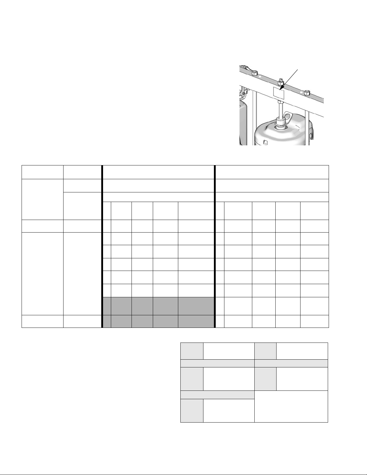
Models
Models
Check the identification plate (ID) for the 6-digit part number of your warm melt
supply system. Use the following matrix to define the construction of your system,
based on the six digits. For example, Part No. WM2979 represents a Warm Melt
supply system (WM), a carbon steel Check-Mate 200 Severe Duty
pump with an NXT 3400 air motor (pump code 29), a 6.5 in. dual post ram with
integrated air controls (7) and a 55-gallon, uncoated platen with an EPDM seal
(9).
NOTE: Some configurations in the following matrix cannot be built. See the
Product Selection guide for available systems.
®
displacement
ID
To order replacement parts, see Parts section in this manual and in manual
313527. The digits in the matrix do not correspond to the Ref. Nos. in the Parts
drawings and lists.
WM 29 7
First and
Second Digit
WM
(Warm Melt
Single Supply
System)
TW
(Warm Melt
Tandem
Supply
System)
Third and
Fourth Digit Fifth Digit
Ram Options
DataTra
Pump Code
Size Style
k
Voltage Air Controls
4 3 in. D60 no volt INT
5 3 in. D200 no volt INT
6 3 in D200i no volt
(See Table 1
for 2-digit
Pump Code)
7 6.5 in. D200s no volt INT
8 6.5 in. D200si no volt
Y 3 in. D60i no volt
2-Button
Interlock
2-Button
Interlock
2-Button
Interlock
F
H
L
R
U
Y
8
9
TI11157A
9
Sixth Digit
Platen and Seal Options
Platen
Size
20 L
(5 Gal) F, SW SST
20 L
(5 Gal) F, DW CS
30 L
(8 Gal) F, SW SST
30 L
(8 Gal) F, DW CS
60 L
(16 Gal) F, SW SST
60 L
(16 Gal) F, DW CS
200 L
(55 Gal) DR
200 L
(55 Gal) DR AL EPDM
Platen
Style
Platen
Material
PTFE
coated
AL EPDM
Seal
Material
PTFE
coated
Polyure-
thane
PTFE
coated
Polyure-
thane
PTFE
coated
Polyure-
thane
Key:
D = Dual post ram
i = 2-Button interlock
s = 6.5 in. ram
INT = Integrated air controls
F = Flat
SW = Single wiper
DW = Dual wiper
DR = Dual o-ring
4 313296J
Table 1: Check-Mate Pump Identification Code/Part
Pump
Code
NXT 2200/CM 200 NXT 6500/CM 200
NXT 3400/CM 200
Pump Part No. (see
manual 312376)
21 P23LCS 2L P68LCS
22 P23LCM 2M P68LCM
26 P23LSM 2U P68LSM
29 P36LCS
2A P36LCM
2G P36LSM
Pump
Code
Pump Part No. (see
manual 312376)
Page 5
Warnings
Warnings
The following warnings are for the setup, use, grounding, maintenance, and repair of this equipment. The exclamation point symbol alerts you to a general warning and the hazard symbol refers to procedure-specific risk. Refer back
to these warnings. Additional, product-specific warnings may be found throughout the body of this manual where
applicable.
WARNING
ELECTRIC SHOCK HAZARD
This equipment must be grounded. Improper grounding, setup, or usage of the system can cause
electric shock.
• Turn off and disconnect power at main switch before disconnecting any cables and before servicing
equipment.
• Connect only to grounded power source.
• All electrical wiring must be done by a qualified electrician and comply with all local codes and
regulations.
FIRE AND EXPLOSION HAZARD
Flammable fumes, such as solvent and paint fumes, in work area can ignite or explode. To help prevent
fire and explosion:
• Use equipment only in well ventilated area.
• Eliminate all ignition sources; such as pilot lights, cigarettes, portable electric lamps, and plastic drop
cloths (potential static arc).
• Keep work area free of debris, including solvent, rags and gasoline.
• Do not plug or unplug power cords, or turn power or light switches on or off when flammable fumes
are present.
• Ground all equipment in the work area.
• Use only grounded hoses.
• Hold gun firmly to side of grounded pail when triggering into pail.
• If there is static sparking or you feel a shock, stop operation immediately. Do not use equipment
until you identify and correct the problem.
• Keep a working fire extinguisher in the work area.
BURN HAZARD
Equipment surfaces and fluid that’s heated can become very hot during operation. To avoid severe
burns:
• Do not touch hot fluid or equipment.
• Wait until equipment/fluid has cooled completely.
SKIN INJECTION HAZARD
High-pressure fluid from gun, hose leaks, or ruptured components will pierce skin. This may look like just
a cut, but it is a serious injury that can result in amputation. Get immediate surgical treatment.
• Do not point gun at anyone or at any part of the body.
• Do not put your hand over the dispense outlet.
• Do not stop or deflect leaks with your hand, body, glove, or rag.
•Follow Pressure Relief Procedure in this manual, when you stop dispensing and before cleaning,
checking, or servicing equipment.
313296J 5
Page 6
Warnings
WARNING
MOVING PARTS HAZARD
Moving parts can pinch or amputate fingers and other body parts.
• Keep clear of moving parts.
• Do not operate equipment with protective guards or covers removed.
• Pressurized equipment can start without warning. Before checking, moving, or servicing equipment,
follow the Pressure Relief Procedure in this manual. Disconnect power or air supply.
SPLATTER HAZARD
Hot or toxic fluid can cause serious injury if splashed in the eyes or on skin. During blow off of platen,
splatter may occur.
• Use minimum air pressure when removing platen from drum.
TOXIC FLUID OR FUMES HAZARD
Toxic fluids or fumes can cause serious injury or death if splashed in the eyes or on skin, inhaled, or
swallowed.
• Read MSDS’s to know the specific hazards of the fluids you are using.
• Store hazardous fluid in approved containers, and dispose of it according to applicable guidelines.
• Always wear impervious gloves when spraying or cleaning equipment.
• If this equipment is used with isocyanate material, see additional information on isocyanates in Isocyanate Conditions Section of this manual.
EQUIPMENT MISUSE HAZARD
Misuse can cause death or serious injury.
• Do not operate the unit when fatigued or under the influence of drugs or alcohol.
• Do not exceed the maximum working pressure or temperature rating of the lowest rated system
component. See Technical Data in all equipment manuals.
• Do not leave the work area while equipment is energized or under pressure. Turn off all equipment
and follow the Pressure Relief Procedure in this manual when equipment is not in use.
• Check equipment daily. Repair or replace worn or damaged parts immediately with genuine manufacturer’s replacement parts only.
• Do not alter or modify equipment.
• Use equipment only for its intended purpose. Call your distributor for information.
• Route hoses and cables away from traffic areas, sharp edges, moving parts, and hot surfaces.
• Do not kink or over bend hoses or use hoses to pull equipment.
• Keep children and animals away from work area.
• Comply with all applicable safety regulations.
PERSONAL PROTECTIVE EQUIPMENT
You must wear appropriate protective equipment when operating, servicing, or when in the operating
area of the equipment to help protect you from serious injury, including eye injury, inhalation of toxic
fumes, burns, and hearing loss. This equipment includes but is not limited to:
• Protective eyewear
• Clothing and respirator as recommended by the fluid and solvent manufacturer
•Gloves
• Hearing protection
6 313296J
Page 7
Overview
Overview
System Description
Warm melt supply systems are used for melting and
pumping warm melt adhesives and high viscosity sealants.
The system consists of an air-powered ram that drives a
Check-Mate pump and a heated platen into a drum of
material. The heated platen heats the material and the
pump removes it from the drum. The material is then
pushed through a supply hose to the applicator.
All features of the warm melt supply system are controlled by Graco Control Architecture components: Fluid
Control Module (FCM), Temperature Control Modules
(TCM), and the display module. The FCM controls the
motor and pump, and the TCMs control the heaters. The
display module provides the user interface for the entire
warm melt supply system.
Power Requirements
A 30A (minimum) - 60A (maximum) circuit breaker (not
provided) must be installed on the incoming power supply. See Table 1, and Technical Data, page 106, for
more information regarding electrical requirements.
Table 1: Electrical Requirements
AC Panel
Voltage HZ Phase
240 50/60 1 57.0
Full Load
Amps
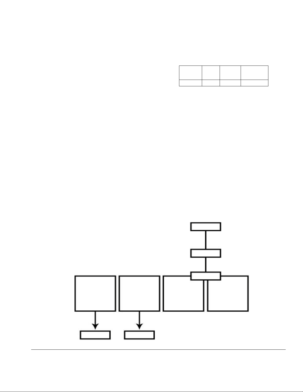
Heat Control Zone Selection
Warm melt supply systems have four heat zones (see
F
IG
. 1).
• Zones 1 and 2 are always used for the heated
platen and the heated pump respectively.
• Zones 3 and 4 are used for the heated hose and
valve. These zones are rated for 1920 watts at 240
volts.
Heated hoses have a 16-pin connector on the inlet end
cable, and an 8-pin connector on the outlet end cable.
All heated valves, manifolds, and heaters are equipped
with an 8-pin matching connector. Accessory cables are
available for other possible combinations.
ZONE 1
Control
Platen
FIG. 1: Heat Control Zone Selection
ZONE 2
Control
Pump
Valve 1
ZONE 3
Control
1920 Watts max
Hose 1
ZONE 4
Control
1920 Watts max
313296J 7
Page 8
Component Identification
Component Identification
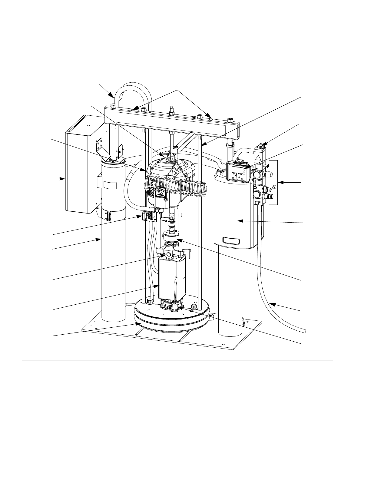
Single Supply Systems
D200s Ram Shown
AF
S
Lift Locations
NOTE: Do not
use air motor lift
ring (S) to lift
entire system.
V
AD
C
H
AE
G
J
K
A
U
D
X
Z
E
T
FIG. 2: Single Supply System
Key:
ARam Assembly
C Air Motor
D Heated Check-Mate Displacement Pump
E Heated Platen
G Display Module
H Electrical Enclosure
IG
J Integrated Air Controls (see F
K Fluid Control Module (inside shroud)
S Lift Ring (air motor)
T Platen Bleed Port
U Pump Outlet
8 313296J
. 4)
V Platen Lift Rod
XWet Cup
Z Main Air Line (not supplied)
AD Air Motor Solenoid
AE Junction Box
AF Cable Track
Page 9
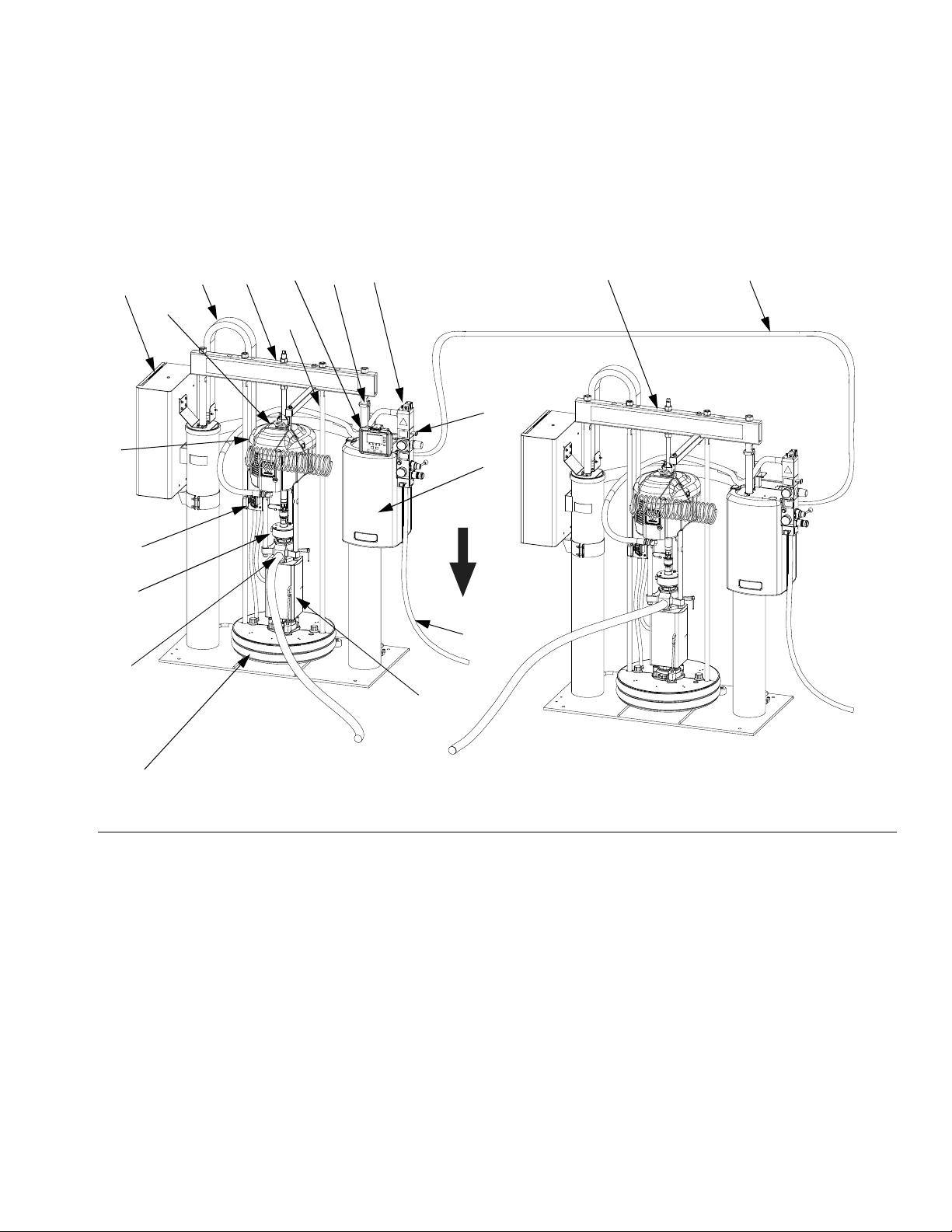
Tandem Supply Systems
D200s Rams Shown
Component Identification
Supply System A
A
H
AF
G
AD
F
Supply System B
B
N
S
V
J
C
K
AE
To heated
X
manifold
(243697)
Z
U
D
E
FIG. 3: Tandem Supply System
Key:
ARam A
BRam B
C Air Motor
D Heated Check-Mate Displacement Pump (Ram A and B)
E Heated Platen (Ram A and B)
F Drum Empty Sensor (partially hidden; Ram A and B)
G Display Module (Ram A only)
H Electrical Enclosure (Ram A and B)
J Integrated Air Controls (Ram A and B); see page 10
K Fluid Control Module (inside shroud, Ram A and B)
N CAN Communication Cable
S Lift Ring (Air Motor)
T Platen Bleed Port
U Pump Outlet
V Platen Lift Rod
r_wm2179_313269_4a
XWet Cup
Z Main Air Line (not supplied)
AD Air Motor Solenoid (Ram A and B)
AE Junction Box (Ram A and B)
AF Cable Track (Ram A and B)
313296J 9
Page 10
Component Identification
NOTE:
See F
IG
. 2 and FIG. 3. Before you install the system,
you should be familiar with the following components.
Reference numbers and letters in parentheses in the
text refer to the callouts in the figures.
Both rams (A and B) include a Check-Mate Pump (D),
platen (E), integrated air controls (J), drum empty sensor (F), and fluid control module (K).
Only Ram A includes the display module (G).
• Drum empty sensor (F). Signals drum empty condi-
tion. See F
IG
. 11, page 19.
• Display module (G). Mounted on Ram A only. Pro-
vides Run Mode status screens, Setup screens, and
control keys. See F
• Fluid control module (K). See F
• Integrated air controls (J). See F
IG
. 8, page 13.
IG
. 7, page 12.
IG
. 4.
• Air motor solenoid (AD). Solenoid is on when the
selected ram is on and in Run Mode, Recirculate
Mode, or Prime Mode. Solenoid is off when system
is shut off or when in Depressurize Mode, or the ram
is in an Inactive Ready Mode. The solenoid LED will
illuminate when the solenoid is on.
• Depressurize/recirculate fluid valve. Depressurizes
system when Depressurize Mode is active. Recirculates fluid when Recirculate Mode is active.
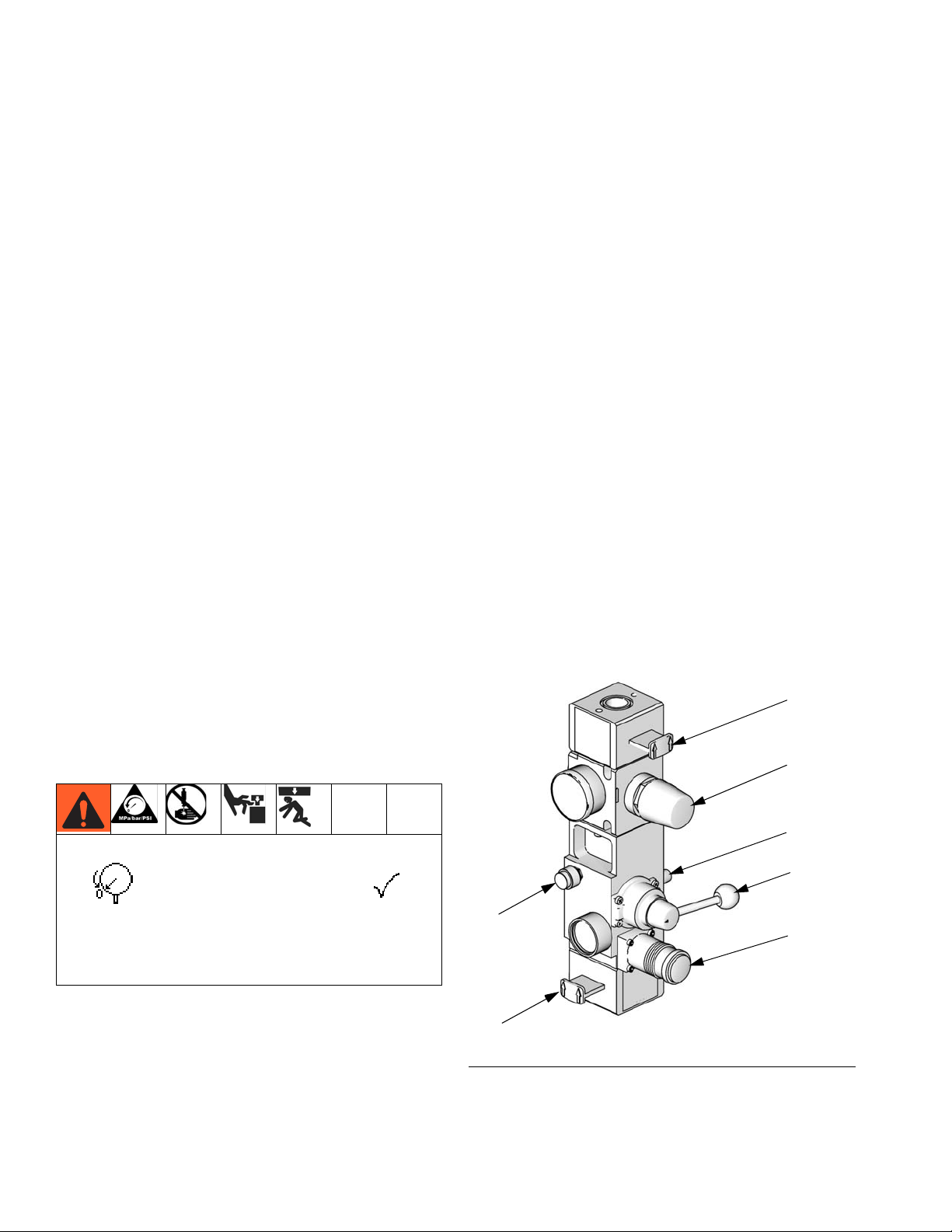
Integrated Air Controls
D60, D200, and D200s Models
The integrated air controls include:
• Main air slider valve (BA): turns air on and off to
the system. When closed, the valve relieves pressure downstream.
• Ram air regulator (BB): controls ram up and down
pressure and blowoff pressure.
• Ram director valve (BC): controls ram direction.
• Exhaust port with muffler (BD)
• Air motor regulator (BE): Controls air pressure to
motor.
• Air motor slider valve (BF): turns air on and off to
the air motor. When closed, the valve relieves air
trapped between it and the air motor. Push the valve
in to shutoff. The air solenoid (AD), the air motor
valve (BF), and the main air slider valve (BA) must
be open for air to flow.
• Blowoff button (BG): turns air on and off to push
the platen out of an empty drum.
BF
BE
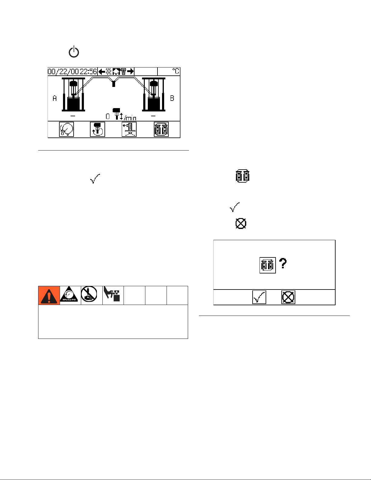
To depressurize the system, press the Depressurize
BD
key on the display module and select
when asked if you want to depressurize the system.
Follow the Pressure Relief Procedure on page 28.
BG
BC
BB
Shutting off power or removing power from the system will not depressurize the system.
BA
ti10438a
FIG. 4. Integrated Air Controls
10 313296J
Page 11
Component Identification
Air Line Accessories
See Supply Systems Operation manual.
• Air line drain valve. Not included.
• Air line filter: removes harmful dirt and moisture
from compressed air supply. Not included.
• Second bleed-type air valve isolates air line
accessories and supply system for servicing. Locate
upstream from all other air line accessories. Not
included.
• Air relief valve: automatically relieves excessive
pressure. Not included.
2-Button Interlock Air Controls
D60i, D200i, and D200si Models
Systems that have 2-Button Interlock controls have the
following additional components:
Communications Gateway Module
The Communications Gateway Module (CGM) provides
a control link between Graco Control Architecture based
systems and a selected fieldbus. This provides the
means for remote monitoring and control by external
automation systems.
Data provided by the CGM to the fieldbus depends on
which Graco Control Architecture based system and
fieldbus are connected. A data map supplied on a map
token is defined for this pairing. Once the data map has
been loaded into the CGM, it is stored internally, and the
map token is no longer required for operation.
See the Supply System Communications Gateway Module Installation Kit manual for fieldbus parameter setup
instructions and screen descriptions.
CGM Module Status LED Signals
Signal Description
• 2-Button Module: See the Air Controls manual for
information.
• Roller switch (CA): shuts off air supply when it
contacts the bracket actuator. Operator must push
and hold the activation buttons simultaneously to
resume ram movement.
Activation
Buttons
ti10843a1
F
IG
. 5: 2-Button Module
• Bracket actuator (CB): attaches to the platen lift
rod. When platen is outside of drum, actuator makes
contact with the roller switch.
CA
Green on System is powered up
Yellow Internal communication in progress
Red
Solid
*Red
(7 flashes)
* The red LED will flash a code, pause, then repeat.
See Communications Gateway Module manual
312864 for diagnostic information. Verify that you are
using the correct token for your system and reinstall
token. If fails, order new token.
CGM hardware failure
Data map load failure
Incorrect data map for fieldbus type
No data map loaded
CB
ti10846a
IG
. 6: Roller Switch and Bracket Actuator
F
313296J 11
Page 12
Component Identification
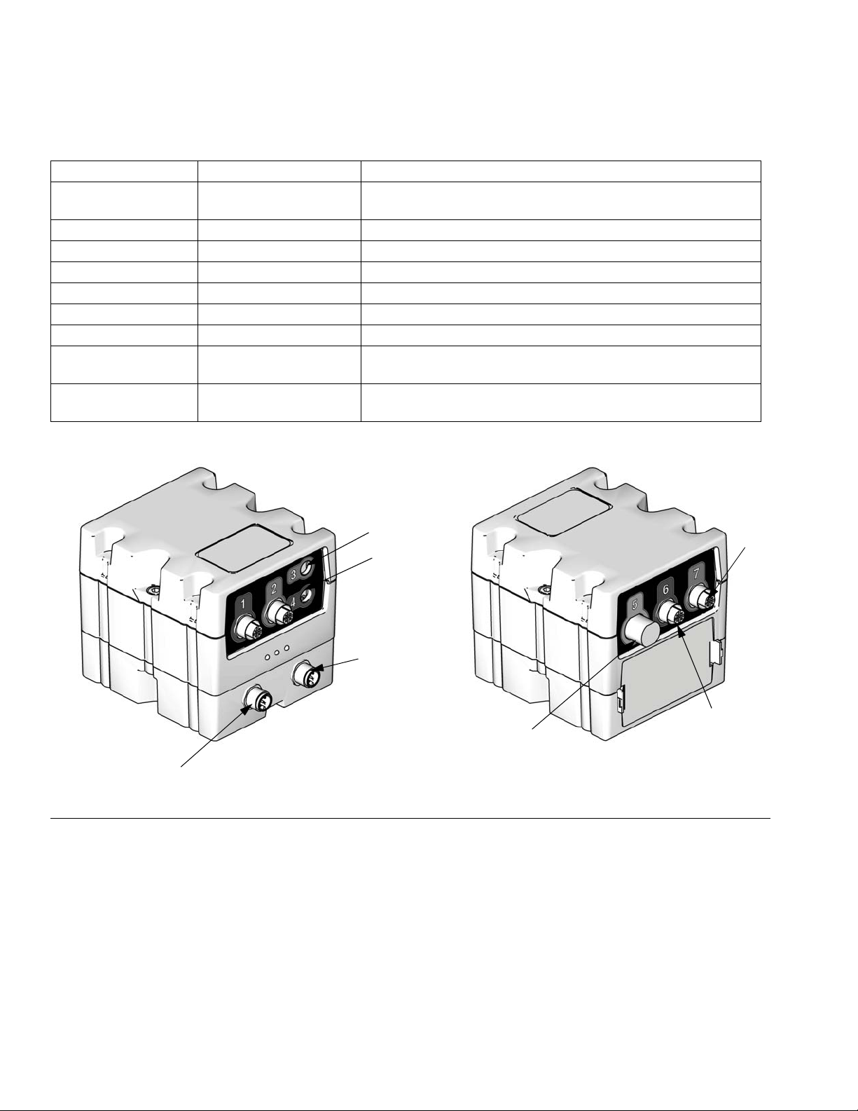
Fluid Control Module
Table 2: FCM Sensor Connections
Connection Ram Sensor Description
1 Ram A and Ram B Air motor solenoid (wire labeled 3), drum low (wire labeled 1),
drum empty (wire labeled 2)
2 Ram A Light tower
3 Ram A + B Fluid depressurize/recirculate solenoid
4 not used not used
5 Ram A and Ram B Air motor reed switch, sensors
6 not used not used
7 Ram A Filter pressure at inlet and outlet
CAN communication
cable 1
CAN communication
cable 2
Ram A From Ram A FCM to display module.
Ram A and Ram B 15 ft (4.57 m) from Ram A FCM to Ram B FCM.
CAN Cable 1
FIG. 7: FCM Sensor Connections
3
4
CAN Cable 2
TI12337A
7
6
5
TI12336A
12 313296J
Page 13
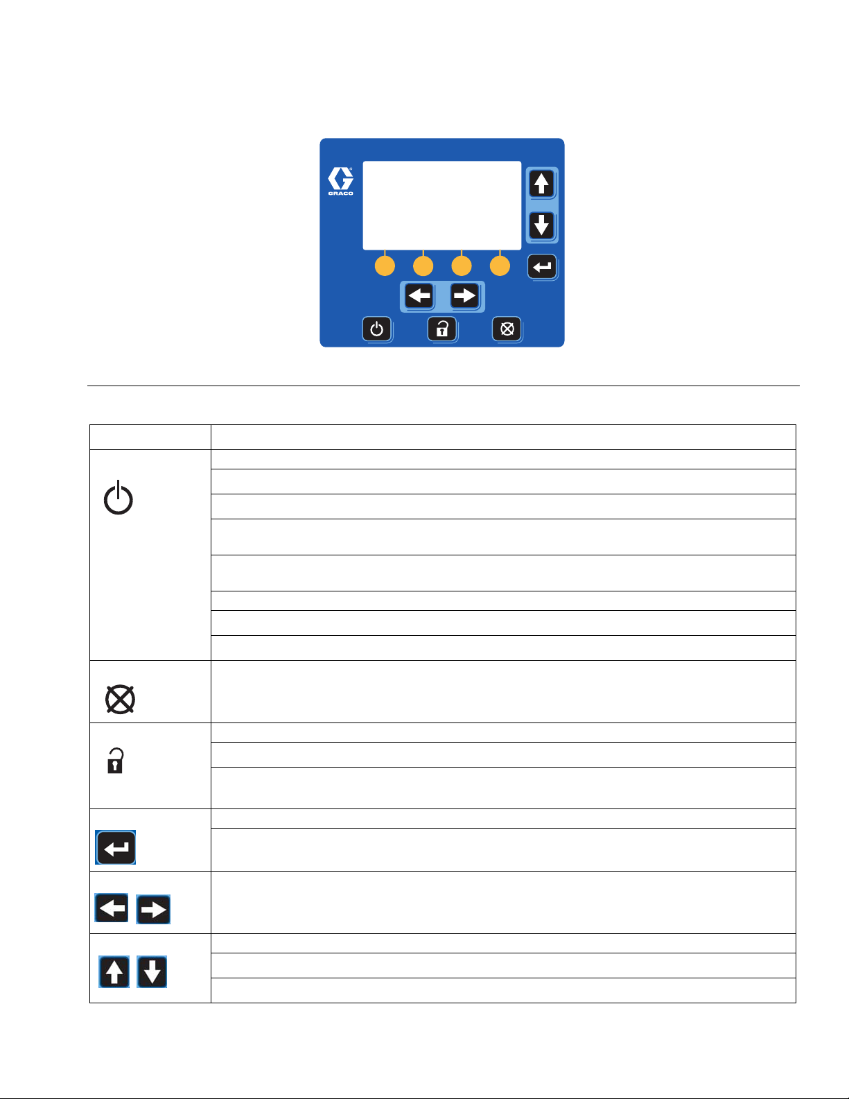
User Interface
FIG. 8: Display Module
Button Function
On/Off
Powers air motor solenoid ON and OFF from Ram Operation screen (F
• When ON, the air motor solenoid is ON and the pump of the active ram is pressurized.
Table 3: Display Module Button Functions
Component Identification
IG
. 71, page 100).
Cancel
Setup
Enter
Arrows Left/Right
• When OFF, the air motor solenoids are OFF.
CAUTION: Turning the air motor solenoid OFF relieves pressure from the pump motor. It does
not depressurize the fluid pressure. Follow the Pressure Relief Procedure, page 28.
NOTE: The ram up/down and blowoff air is independent of the electronic controls and can be
operated anytime the main air slider valve is open and air pressure is available.
Powers heat ON and OFF from Heat Run screen (F
• When ON, the enabled heat zones are ON.
• When OFF, all heat zones are OFF.
Cancel a selection or number entry while in the process of entering a number or making a
selection.
Toggle between run and setup screens.
• Setup changes can be made while system is operating.
• If setup screens are password protected, button toggles between run and password entry
screen.
Opens drop down menus on Setup fields.
Press to enter changes and make a selection.
Navigate left or right to a new screen.
Navigate left or right within a screen while in Jump In mode. See Appendix A - User Interface
Display, page 93, for more information.
IG
. 72, page 101).
Arrows Up/Down
313296J 13
Navigate up or down within a screen or to a new screen.
• Move between selections within a drop-down menu.
• Increment or decrement the selected numerical field within a selection menu.
Page 14
Component Identification
Table 3: Display Module Button Functions
Button Function
Soft Key
Soft keys activate the mode or action represented by the icon above each button in the LCD.
See Table 4 for soft key modes and actions.
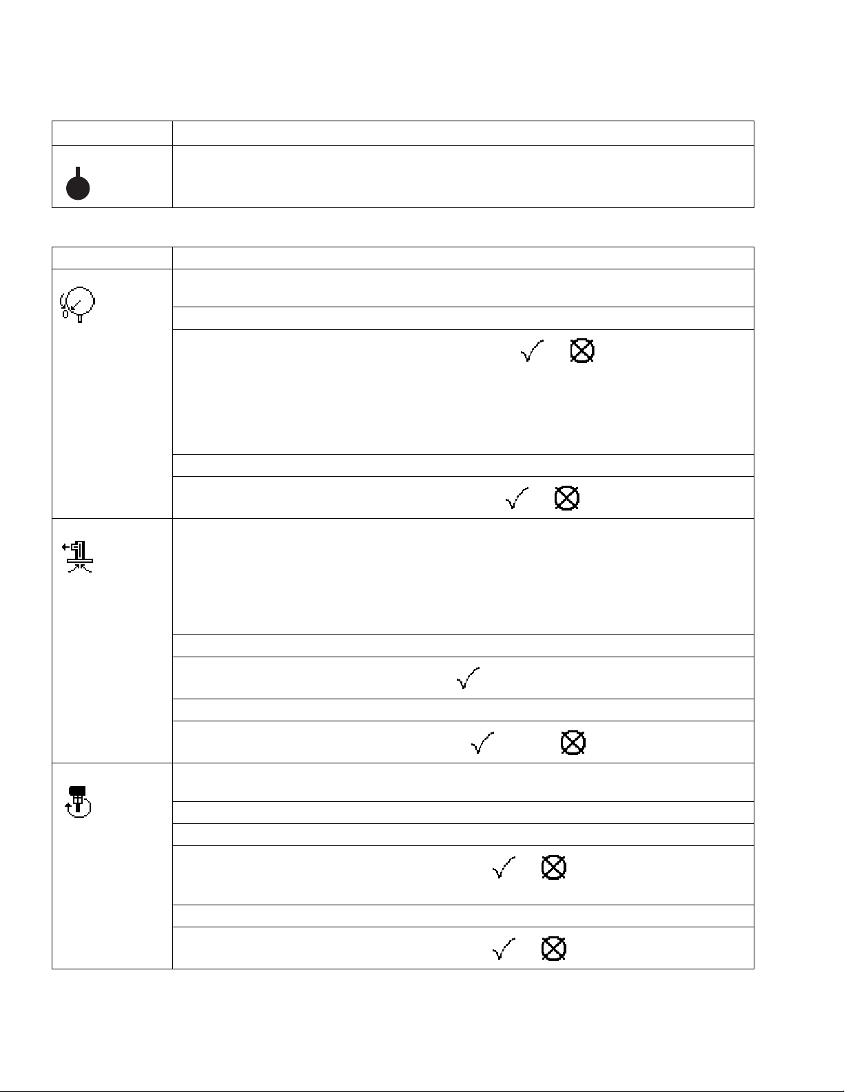
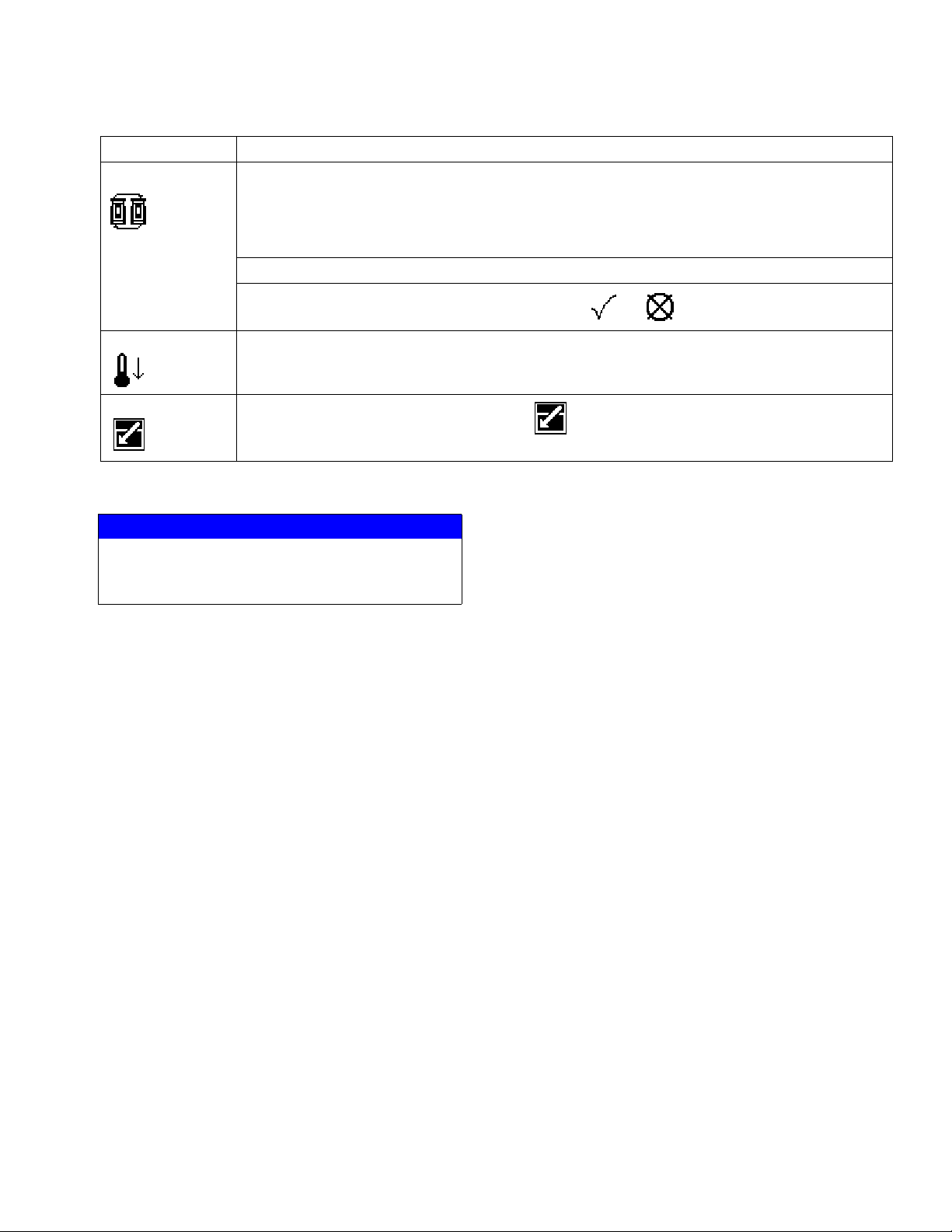
Table 4: Display Soft Key Icons
Icon Function
Depressurize Depressurize relieves fluid pressure from the pump outlet to below the platen on the currently
active ram.
If system is pressurized, press button.
Pump Prime
• When prompted to depressurize the system, select or .
active ram will depressurize both rams.
Depressurizing the
NOTE: If additional user-supplied check valves have been added to the system, only the
active ram will be depressurized. You must perform manual crossover and select depressurize
again to depressurize both rams. See Crossover section of this table on page 15.
If system is depressurized, press button.
• When prompted to pressurize the system, select or .
Pump Prime
•
Tandem ram:
•
Tandem ram:
if pump is off, activates the air solenoid on the active ram;
if pump is on, activates the air solenoid on the inactive ram which enables you
to purge air and prime the pump;
•
Single ram:
activates air solenoid whether or not pump is on;
• clears the Pump Not Primed deviation or alarm (depending on setup selection); and
• resets the drum volume remaining to the drum fill volume setpoint for pump being primed.
Press button.
• When prompted to prime the ram, select to prime.
Press button to exit Prime Mode or to reset counter to the prime time.
• When prompted to exit Prime Mode, select to exit or to reset prime counter.
Recirculate Recirculate Mode pumps fluid from the drum, through the pump, and back into the drum on the
currently active ram.
Set motor air regulator to 30 psi (0.2 MPa, 2.1 bar) before pressing Recirculate key.
If system is not in Recirculate Mode, press button.
• When prompted to turn recirculation on, select or . Adjust motor air regulator to
obtain desired flow rate.
If system is in Recirculate Mode, press button.
• When prompted to turn recirculation off, select or .
14 313296J
Page 15
Component Identification
Table 4: Display Soft Key Icons
Icon Function
Crossover Crossover key transitions the active ram to inactive, and inactive ram to active. Available on
Warm Melt Tandem Supply Systems only.
NOTE: If an alarm is present on the inactive ram, crossover will not be successful. Manual
crossover is disabled in single ram operation.
Press button.
• When prompted to initiate a crossover, select or .
Setback
Setback transitions the heaters into setback mode. The setpoint for each zone will be
decreased by the setback amount. See Heater System Setup Screen, page 95, and Heat
Run Screen, page 101.
Jump In
In screens that have editable fields, press to access the fields and make changes. See
Appendix A - User Interface Display, page 93, for more information.
NOTICE
To prevent damage to soft key buttons, do not
press the buttons with sharp objects such as pens,
plastic cards, or fingernails.
313296J 15
Page 16
Component Identification
User Interface Display
NOTE: For details regarding the user interface display see Appendix A - User Interface Display, page
93.
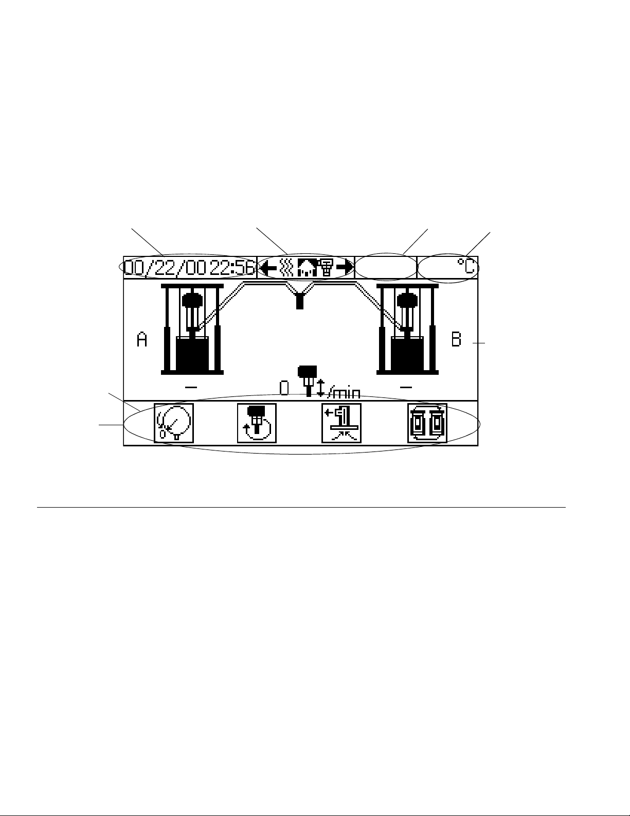
Display Screen Components
The following figure calls out the navigational, status, and general informational components of each display screen.
Current Date and Time
Displays soft keys
that are active for
particular screen
Soft Keys
F
IG
. 9: Display Screen Components
Navigation
Status
Mode
Function Display
16 313296J
Page 17
Installation
Installation
Accessories are available from Graco. Make certain all
accessories are adequately sized and pressure-rated to
meet the system’s requirements.
Component Identification illustrations are only a guide
for selecting and installing system components and
accessories. Contact your Graco distributor for assistance in designing a system to suit your particular
needs.
Location Requirements
•Refer to Dimensions, page 104, for ram mounting
and clearance dimensions.
• Install indoors only, and not near water or any other
liquid that is sprayed.
Location
NOTICE
Always lift supply system at proper lift locations (see
F
IG
. 2) to avoid equipment damage. Do not lift in any
other way.
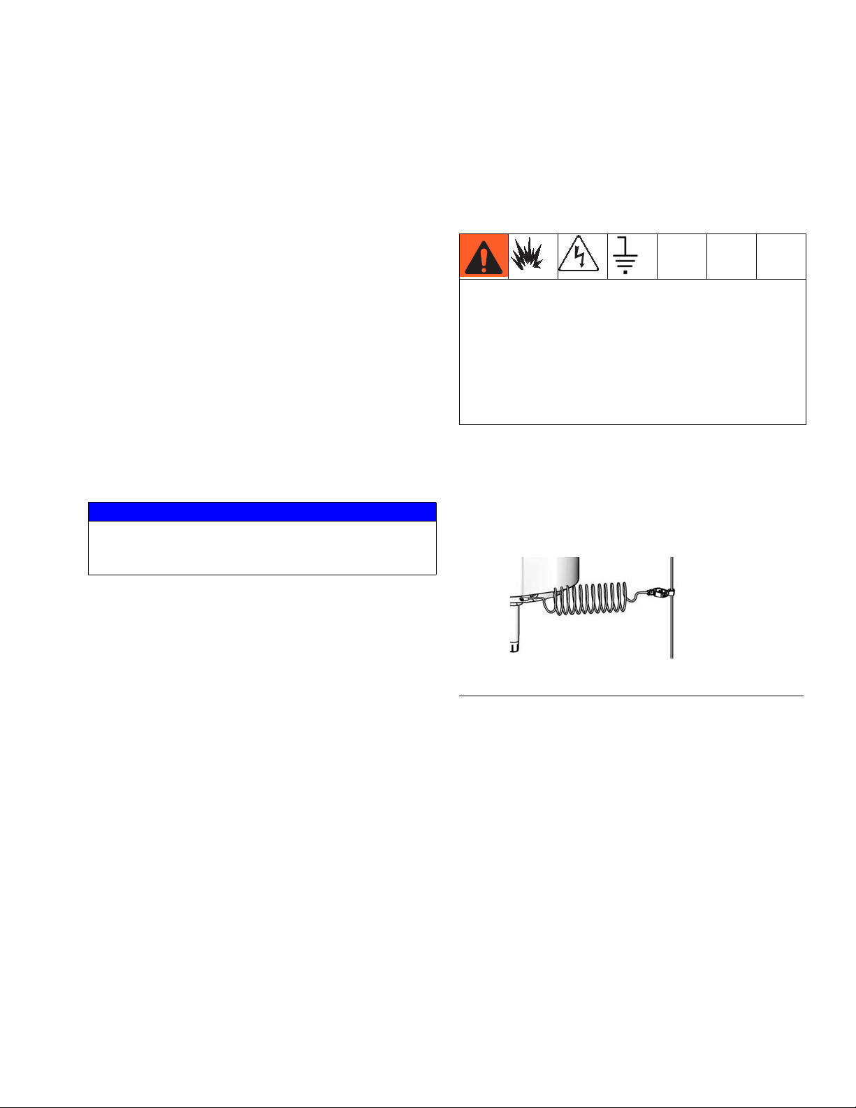
Grounding
Ground the supply system as instructed here and in the
individual component manuals.
The power source conduit is not an adequate ground
for the system. The unit must be bonded to either the
building ground or a true earth ground. To reduce the
risk of static sparking, ground the pump, the object
being dispensed to, and all other dispensing equipment used or located in the dispensing area. All electrical wiring must be done by a qualified electrician
and comply with local codes and regulations.
Pump: use a ground wire and clamp. Loosen grounding
lug locknut and washer. Insert one end of supplied
ground wire into slot in lug and tighten locknut securely.
Connect other end of wire to a true earth ground. See
F
IG
. 10.
1. Attach a lifting sling at the proper lift spots. Lift off
the pallet using a crane or a forklift. See F
proper lift locations.
2. Position the ram so the air controls and electrical
enclosure are easily accessible. Ensure that there is
enough space overhead for the ram to raise fully.
3. Using the holes in the ram base as a guide, drill
holes for 1/2 in. (13 mm) anchors.
4. Ensure that the ram base is level in all directions. If
necessary, level the base using metal shims.
Secure the base to the floor using 1/2 in. (13 mm)
anchors that are long enough to prevent the ram
from tipping.
IG
. 2 for
ti8250a
F
IG
. 10: Ground Pump
Air and fluid hoses: use only electrically conductive
hoses.
Air compressor: follow manufacturer’s recommendations.
Dispense valve: ground through connection to a prop-
erly grounded fluid hose and pump.
313296J 17
Page 18

Installation
Fluid supply container: follow local code.
Object being sprayed: follow local code.
Solvent pails used when flushing: follow local code.
Use only conductive metal pails, placed on a grounded
surface. Do not place the pail on a nonconductive surface, such as paper or cardboard, which interrupts
grounding continuity.
To maintain grounding continuity when flushing or
relieving pressure: hold metal part of the dispense
valve firmly to the side of a grounded metal pail, then
trigger the valve.
Connect Power Source
The electrical enclosure comes already attached and
wired to the ram; however, before the supply system
becomes functional you must connect the electrical
enclosure to a power source.
NOTE: See Power Requirements, page 7, for circuit
protection requirements.
1. Open electrical enclosure door and locate power
line filter.
2. Have a qualified electrician perform the following
steps:
a. Connect your plant power to the electrical
enclosure power line filter according to local
codes. A 1-3/8 in. (35 mm) diameter opening is
provided on the side of the enclosure adjacent
to the label. This opening is suitable for a 1 in.
npt conduit or strain relief fitting (supplied).
b. Connect a power protective ground to the cen-
ter post on the line end of the power line filter.
NOTE: Install safety insulation boots (supplied) on
the power line. Install 1/4 in. ring lugs (user supplied) on the power line and power protective
ground line prior to connecting to the power line filter posts.
Have a qualified electrician connect power according
to national, state, and local safety and fire codes.
NOTE: Required voltage and amperage is noted on
the electrical enclosure label. Also see Table 1.
Before running power to the unit, make sure the
plant electrical service meets the supply system’s
electrical requirements.
18 313296J
Page 19
Installation
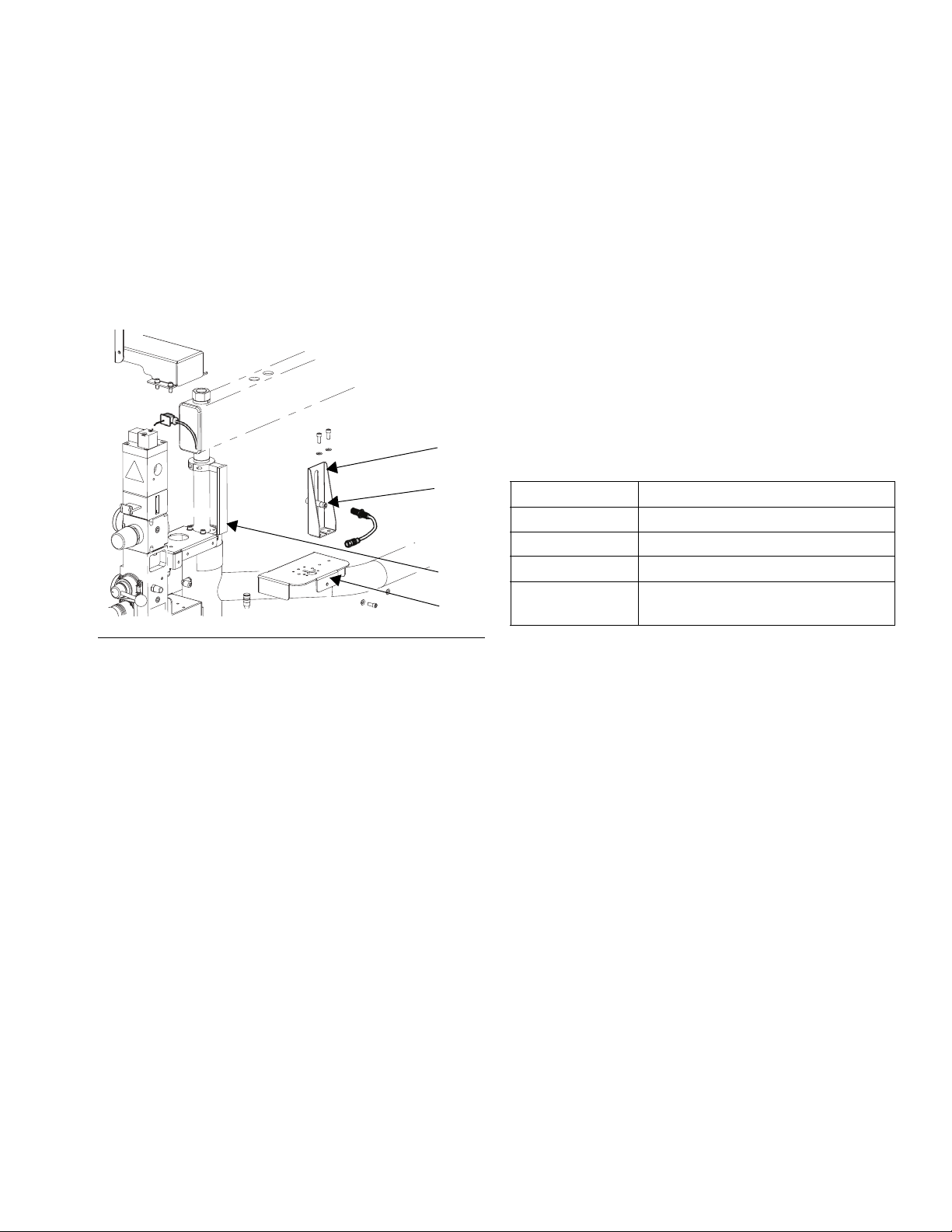
Install/Adjust Drum Low or Empty Sensor
1. Position ram at desired level (low or empty).
NOTE: Follow Steps 2 through 4 only if installing the
low sensor.
2. Attach the low sensor to the existing sensor bracket
(EA), above the existing empty sensor (EE).
D200 Shown
EA
EE
ED
EB
F
IG
. 11: Low or Empty Sensor Kit
4. Attach the sensor to the corresponding connector
on the splitter cable. For drum low, attach the sensor to connector 1. For drum empty, attach the sensor to connector 2.
5. Power system on.
6. Make precise adjustments by moving the sensor
within the slot on the sensor bracket. Use the yellow
indicator on the sensor cable to indicate a drum low
or empty condition.
Light Tower Accessory
Order the 255468 Light Tower Accessory as a diagnostic indicator for supply systems. See T
description of light tower signals.
Table 5: Light Tower Signals
Signal Description
Yellow flashing A low priority error exists.
Yellow on A medium priority error exists.
Red flashing A high priority error exists.
Red on The system is shut down due to
error conditions.
ABLE
5 for a
3. Replace the existing cable between the empty sensor (EE) and FCM connector (see F
with the empty/low sensor splitter cable.
IG
. 7, page 12)
313296J 19
Page 20
Installation
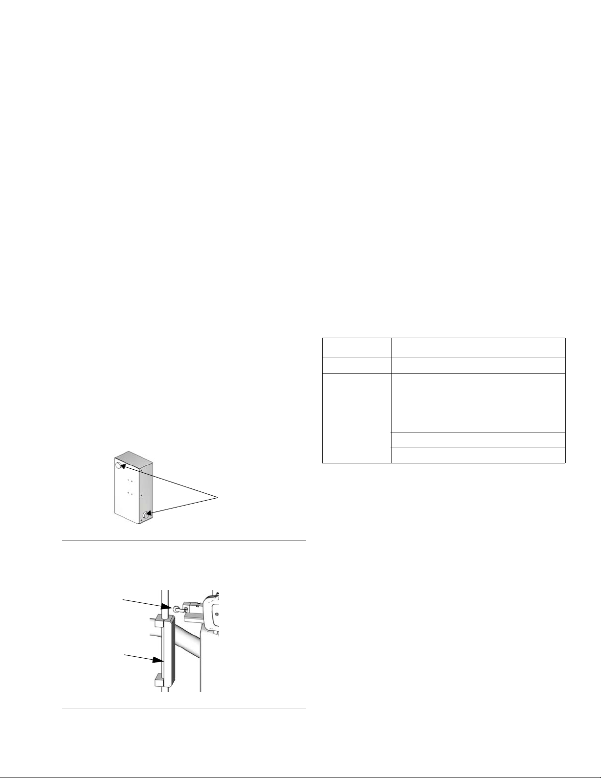
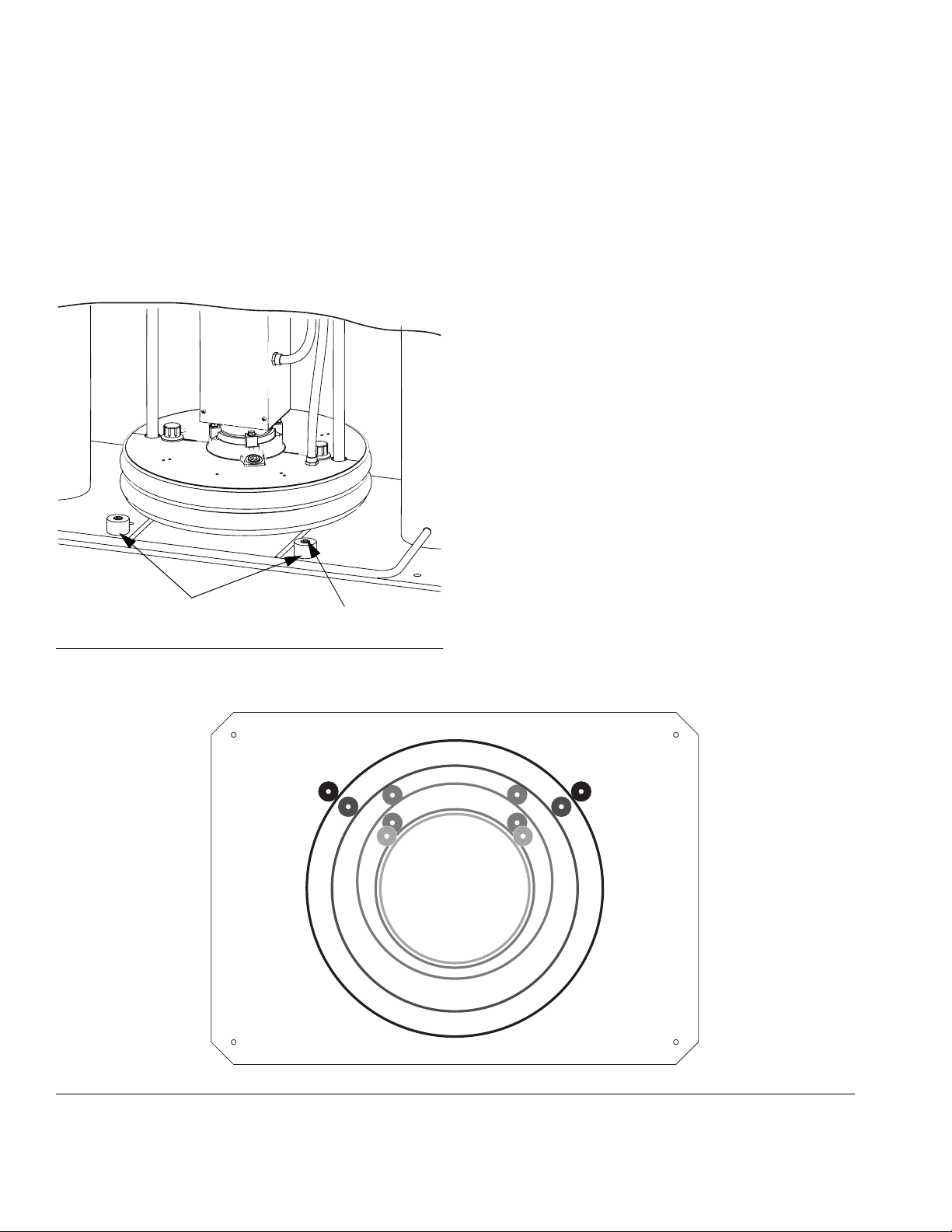
Attach Drum Stops
Supply systems are shipped with drum stops in place to
help position the drum on the ram. For replacement
parts, order Kit 255477. The kit includes two each of
capscrews (FA), lock washers (not shown), and drum
stops (FB).
D200 Shown
1. Locate the correct set of mounting holes on the ram
base.
2. Using the capscrews (FA) and lock washers (not
shown), attach the drum stops (FB) to the ram base.
FB
F
IG
. 12: Attach Drum Stops
FA
55 gal (200 L)
30 gal (115 L)
8 gal (30 L)
5 gal (20 L)
IG
. 13: Drum Stop Location
F
20 313296J
Page 21
Installation
Check Resistance
Check the Resistance Between the Supply
System and the True Earth Ground
The resistance between the supply system components and true earth ground must be less than 0.25
ohms.
Have a qualified electrician check the resistance
between each supply system component and the true
earth ground. The resistance must be less than 0.25
ohms. If the resistance is greater than 0.25 ohms a different ground site may be required. Do not operate the
system until the problem is corrected.
NOTE: Use a meter that is capable of measuring
resistance at this level.
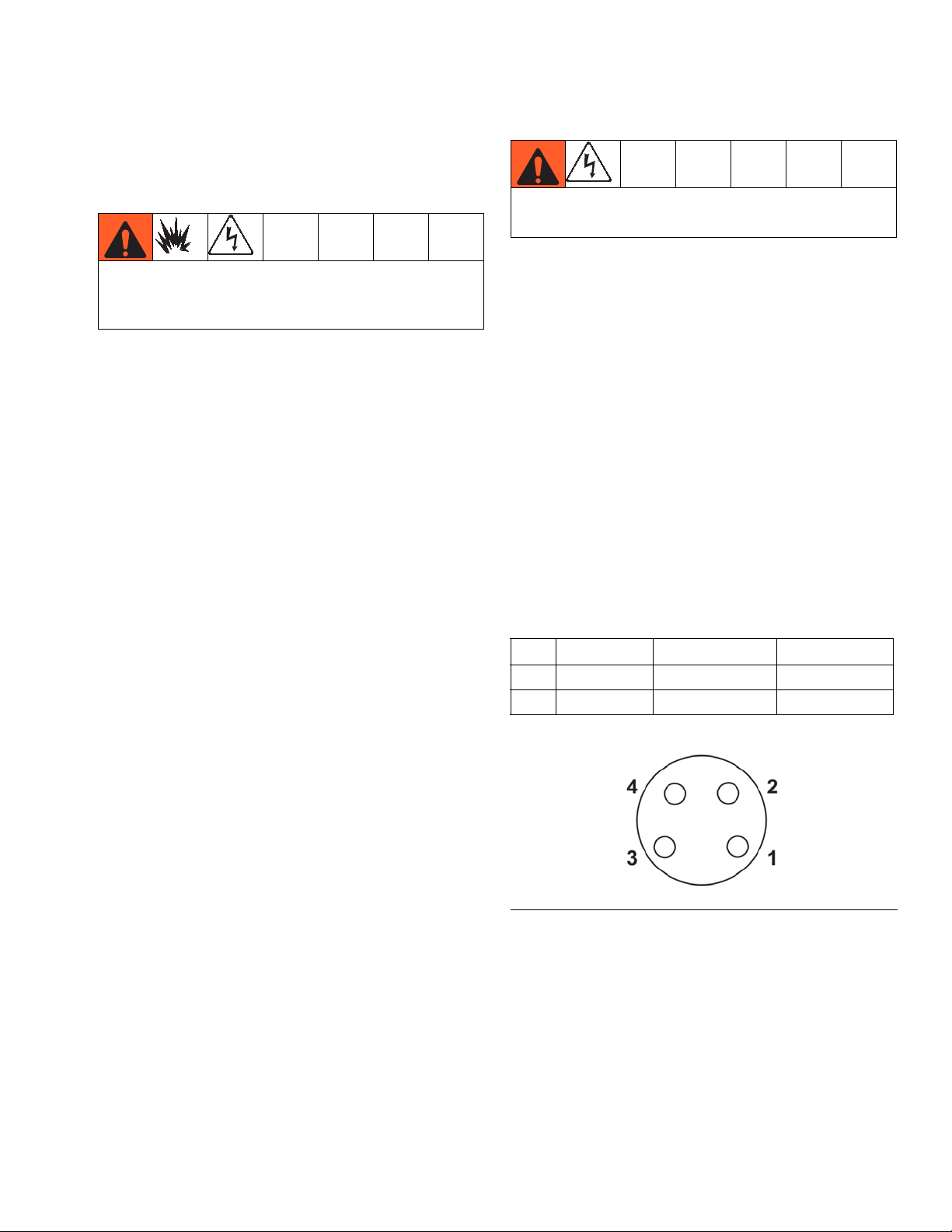
Sensor Resistance Checks
Conduct these electrical checks with the main disconnect OFF.
NOTE: For dispense valve and hose sensor resistance checks, refer to your dispense valve manual
or hose manual.
The supply system includes a heat sensor and controller
for each of the four heated zones. To check sensor
resistance:
1. Make sure the power is off and that the disconnect
switch is in the OFF position.
2. Make electrical resistance checks for the components.
3. Replace any parts that have resistance readings
that do not comply with the ranges listed in Table 6.
NOTE: Check resistance at ambient room temperature (63°– 77°F [17°– 25°C]
Table 6: RTD Sensor Resistance
Zone Component Connector Pin Range (ohms)
1 Platen Pin 1 to 3
2 Fluid Pump Pin 1 to 3
FIG. 14: RTD Connector Pins
).
1050-1100
1050-1100
Ω
Ω
313296J 21
Page 22
Installation
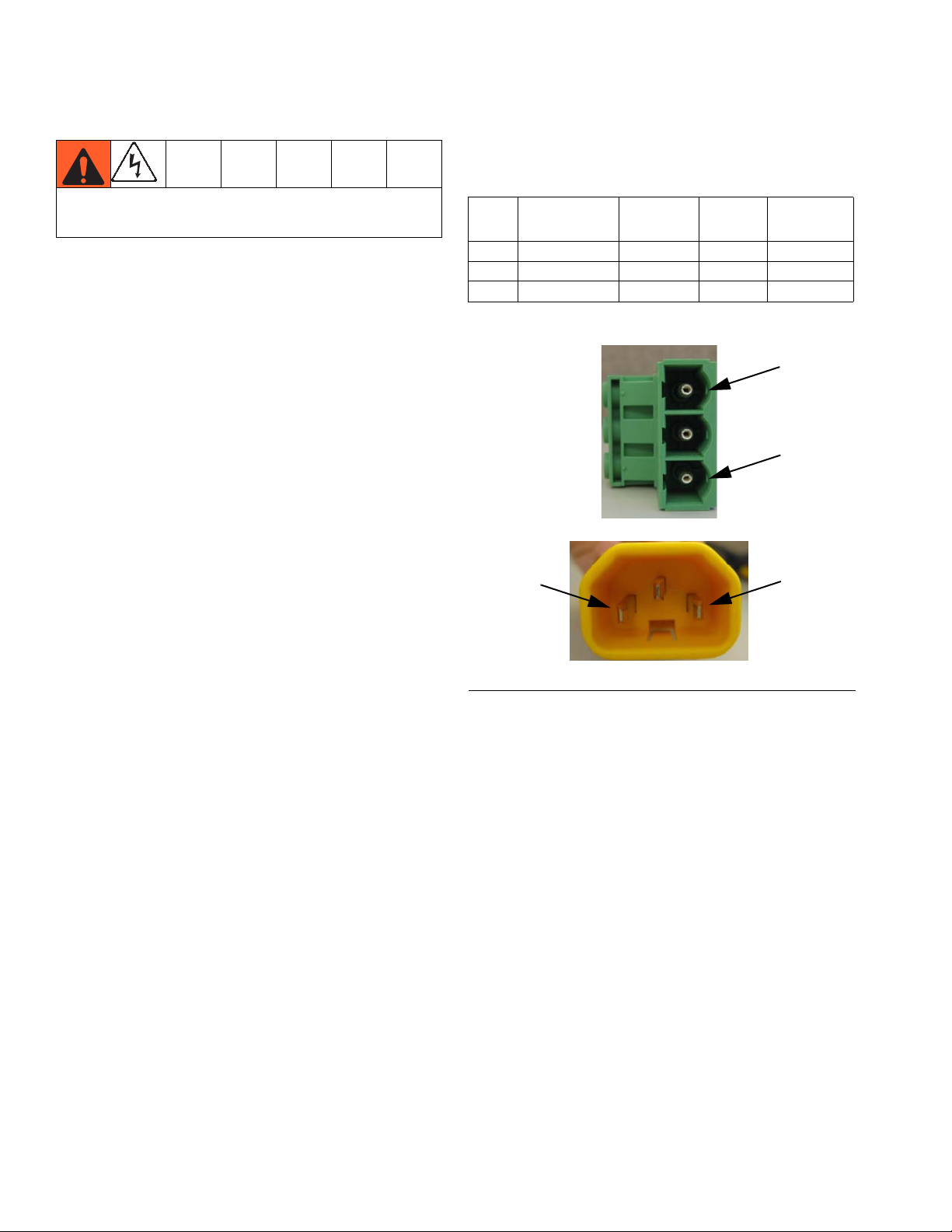
Heater Resistance Checks
Conduct these electrical checks with the main power
disconnect OFF.
NOTE: For dispense valve and hose sensor resistance checks, refer to your dispense valve manual
or hose manual.
To check heater resistance:
1. Make sure the power is off and that the disconnect
switch is in the OFF position.
2. Make electrical resistance checks for the components. Refer to Table 7. Heater terminal pins are
located on the back of the enclosure (H). See F
page 8.
3. Replace any parts whose resistance readings do
not comply with the ranges listed in Table 7.
IG
. 2,
NOTE: Check resistance at ambient room temperature (63°– 77°F [17°– 25°C]
).
Table 7: Resistance Chart of All Heaters
Between
Zone Component
1 Platen - D200 1 and 3 240 15 +5/-5
2 Platen - D60 1 and 3 240 80 +10/-10
3 Pump L and N 240 37 +5/-5
Terminals
Unit
Voltage
Range
(ohms)
1
3
L
FIG. 15: Heater Terminal Pins
N
22 313296J
Page 23
Installation
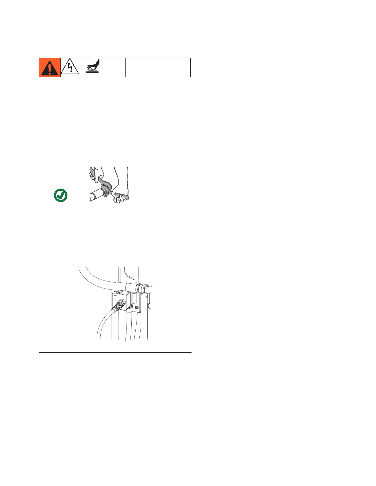
Hose Installation and Care
NOTE: The warm melt supply system requires
Graco single-circuit material hoses rated at a maximum of 1920 Watts.
Hose Installation
1. Connect heated hose to the pump outlet.
2. Use two wrenches to tighten. Torque to 470-550
in-lbs (53.1-62.1 N•m).
3. Wrap exposed fittings on the pump outlet with
Nomex insulation and secure insulation using fiberglass tape.
Mechanical Setup
1. Fill displacement pump wet cup 2/3 full with Graco
Throat Seal Liquid (TSL).
2. Turn all air regulators to their full counterclockwise
position.
3. Connect a 3/4 in. (19 mm) air line from an air source
to the system air inlet. Refer to the pump performance curves in the Check-Mate Pump Packages
manual to determine your air supply flow requirements.
NOTE: Quick disconnects restrict flow for large air
motors.
Overview of Temperature Control Settings
Temperature controls are set in Setup mode. See Setup
Mode Screens on page 95 for information about setting
temperature controls.
See Run Mode Screens on page 100 for information on
controlling temperatures for each zone.
4. Connect hose adapter to green receptacle on junction box.
FIG. 16: Connect Hose to Junction Box
5. Securely tighten the 16-pin electrical connectors on
long heated hose leads into 16-socket receptacles
on the end of the hose adapter.
6. Securely tighten the 8-socket electrical connectors
on short heated hose leads into 8-pin receptacle
located on the dispense valves.
Hose Care Guidelines
Refer to the Hotmelt/Warm Melt Heated Hose manual
for details regarding hose care guidelines.
313296J 23
Page 24

Setup
Setup
The pump was tested with lightweight oil, which is left in
the fluid passages to protect parts. To avoid contaminating fluid with oil, flush the pump with a compatible solvent before use. See Purge System, step 2.
Purge System
Purging the system before the initial use can prevent
material contamination, which may cause the material to
fail or perform poorly.
NOTICE
Purge the system before performing the initial material
loading procedure. The system was factory-tested
using a light soluble oil, a soybean oil, or some other oil
as tagged. Flush the system to avoid contaminating the
material that has been designated for initial material
loading.
To purge the system perform the following procedure:
This equipment should not be used with more than
one type of fluid due to potential compatibility issues
that could result in an unpredictable reaction. Graco
recommends using new hoses when chemicals are
changed or care must be taken to assure that all
traces of one chemical are removed before introducing a second chemical.
3. Select a container of material that can eliminate the
factory-test oil from the system. If necessary, check
with Graco or the material supplier for a recommended solvent.
4. Before purging ensure the entire system and waste
container are properly grounded.
NOTE: Remove any dispense valve orifices before
purging. Reinstall after purging has been completed.
1. Select the material for the initial material load.
2. Verify whether the factory-test oil and the initial
material load are compatible:
a. If the two substances are compatible, omit the
remaining steps in this procedure and refer to
the start up and operation instructions.
b. If the two substances are incompatible, perform
the remaining steps in this procedure to flush
the system at ambient temperature.
Use fluids that are chemically compatible with the
equipment wetted parts. See the Technical Data sections in the equipment manuals.
5. Purge the material through the system for approximately 1 to 2 minutes.
6. Remove the container if purge material was used.
Set Values on Display Module
Set desired values on display module Setup menus.
See Setup Mode Screens, page 95.
24 313296J
Page 25
Setup
Load Material
Moving parts can pinch or amputate fingers. When
the pump is operating and when raising or lowering
the ram, keep fingers and hands away from the
pump intake, platen, and lip of the drum.
NOTICE
Do not use a drum of material that has been dented or
otherwise damaged; damage to the platen wiper can
result.
NOTE: Before loading material, ensure that there is
a minimum overhead clearance of 105 in. (267 cm)
and all air regulators are backed off to their full
counterclockwise position.
NOTE: Follow steps below for both rams if using a
tandem warm melt supply system.
1. Refer to F
lators and air valves.
IG
. 2, FIG. 3, and FIG. 4. Close all air regu-
D200 Shown
J
D
FIG. 17: Heated Platen
8. Set the director valve (BC) to DOWN and lower the
ram until fluid appears at the top of the platen bleed
port (J). Adjust ram air regulator (BB) as needed.
Set the director valve (BC) to neutral and close the
platen bleed port (J). 2-Button Interlock: If system
has this feature, press and hold both buttons to start
lowering the ram. See F
IG
. 5, page 11.
2. Open main air slider valve (BA) and set ram air regulator (BB) to 40 psi (0.28 MPa, 2.8 bar). Set director valve handle (BC) to UP and let the ram rise to
its full height. 2-Button Interlock: If the system has
this feature, ram will stop as it nears the top. Press
and hold both buttons to raise ram completely. See
F
IG
. 5 on page 11.
3. Lubricate the platen seals (D) with grease or other
lubricant compatible with the fluid you will pump.
4. Remove the drum cover and smooth the surface of
the fluid with a straightedge.
5. Put a full drum of fluid on the ram base, slide it back
against the drum stops, and center it under the
platen (D). An optional drum roller kit is available to
make it easier to load the drum on the base. Order
Kit 255627.
6. Remove bleed stick from platen bleed port (J). See
F
IG
. 17.
7. If drum has a plastic liner, pull it over edge of drum.
Secure liner with tape wrapped around circumference of drum.
313296J 25
Page 26
Setup
System Heat Up
Never pressurize warm melt supply system while
using warm melt materials before turning on heat.
Many warm melt materials tend to expand when heating and may cause a heated hose to burst. Avoid the
potential of bursting a hose by opening the dispense
valve during system heat up and lock the dispense
valve trigger open every time you shut the system
down.
NOTE: Operate at the lowest temperature and pressure necessary for your application.
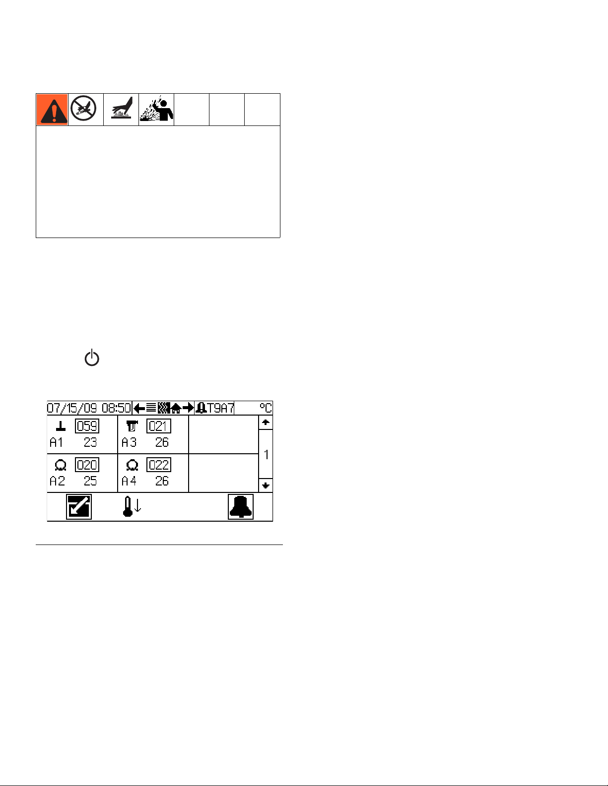
1. Turn the main disconnect on the electrical control
panel door to the ON position.
2. Press while in the Heat Run screen to turn the
heaters on for enabled heat zones.
F
IG
. 18: Heat Run Screen - Ram A
26 313296J
Page 27
Setup
Prime
1. Make sure the system is at required temperature.
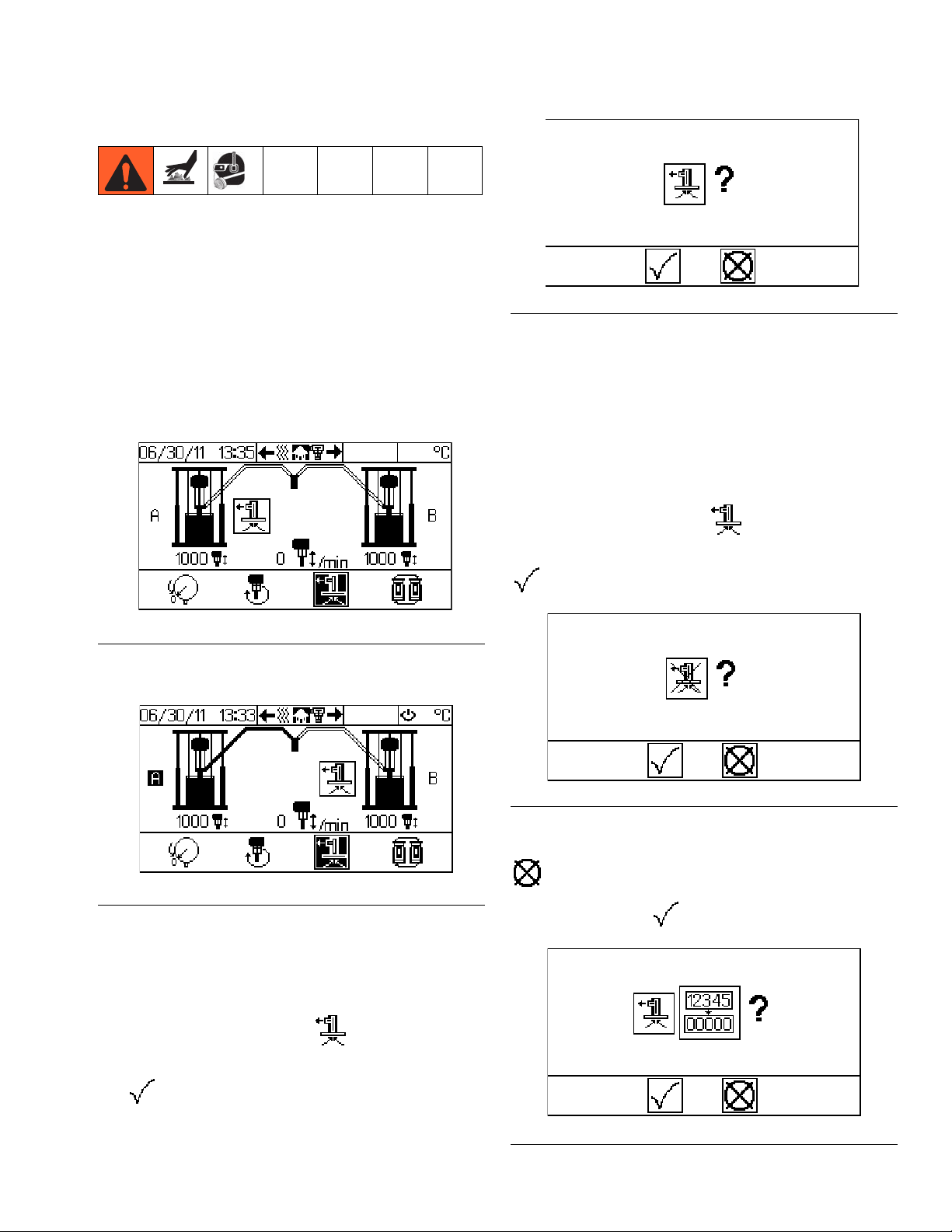
2. Tandem Systems Only: To prime the active ram,
ensure that the system is not in Run Mode. To prime
the inactive ram, ensure that the system is on and in
Run Mode.
3. Single Systems Only: To prime the ram, ensure
that the system is on. The system may or may not
be in Run Mode.
(Prime active ram - not Run Mode)
FIG. 21: Prime Confirmation
6. When the timer expires the air motor solenoid LED
will turn off.
7. Prime the system until a smooth flow of material dispenses from the dispense valve.
8. Lock the dispense valve trigger lock.
NOTE: To exit Prime Mode before the timer expires,
press the Pump Prime key . The display
prompts the operator to confirm. See F
IG
. 22. Select
to exit prime.
FIG. 19: Ram Operation Screen - Tandem System
(Prime inactive ram - in Run Mode)
IG
. 20: Ram Operation Screen - Tandem System
F
4. If using a manual dispense valve, unlock the dispense valve trigger and place dispense valve over a
waste container.
5. Press the Pump Prime key . The display
prompts the operator to confirm. See F
IG
. 21. Select
IG
. 22: Exit Prime Mode Confirmation
F
NOTE: To extend the prime time counter, select
in F
IG
. 22. Display prompts operator to confirm.
IG
See F
. 23. Select to reset.
to begin prime.
IG
. 23: Reset Prime Time Counter Confirmation
F
313296J 27
Page 28
Operation
Operation
Pressure Relief Procedure
This procedure describes how to relieve pressure for the
supply system. Use this procedure whenever you shut
off the system and before checking or adjusting any part
of the system.
1. Lock the dispense valve trigger.
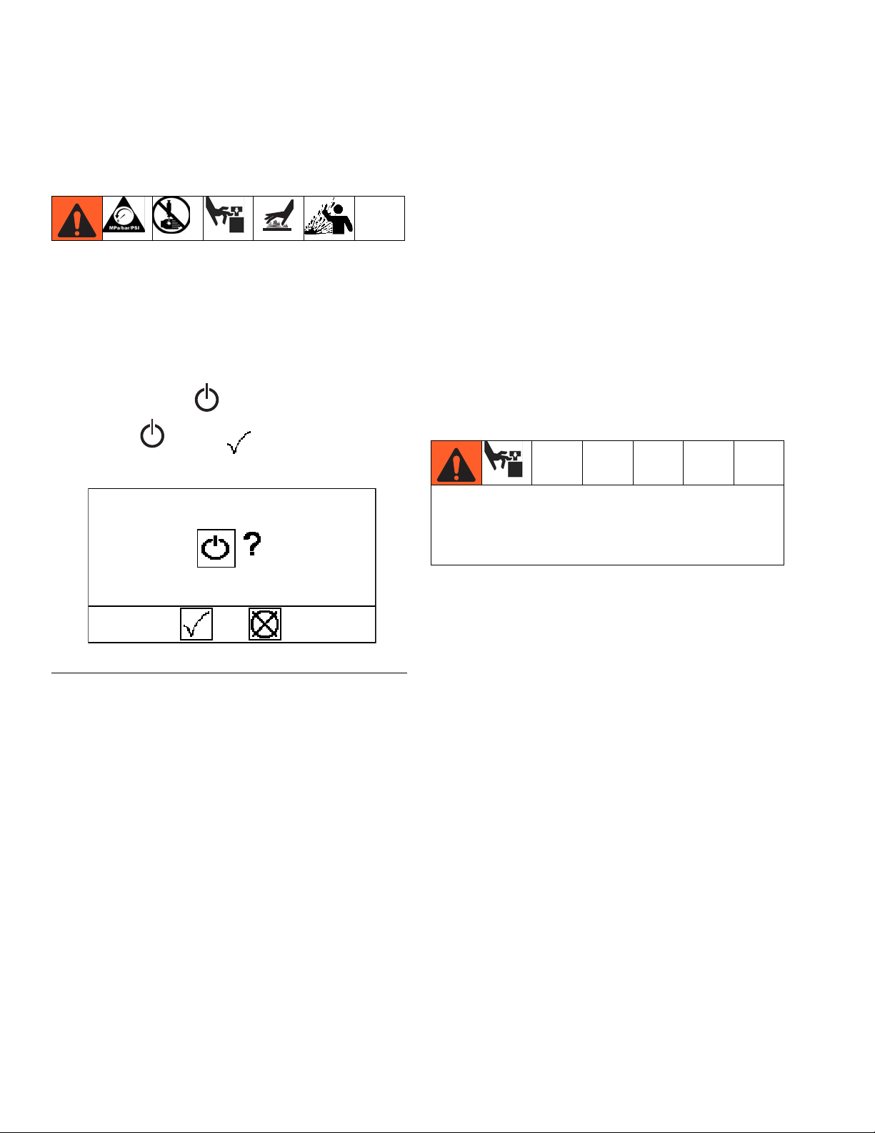
2. Press On/Off key . If system is On, display will
highlight . Select to turn off.
If you suspect that the dispense tip/nozzle or hose is
completely clogged, or that pressure has not been fully
relieved after following the steps above, very slowly
loosen the tip guard retaining nut or hose end coupling
and relieve pressure gradually, then loosen completely.
Now clear the tip/nozzle or hose.
Trigger Lock
Always engage the trigger lock when you stop dispensing to prevent the gun from being triggered accidentally
by hand or if dropped or bumped.
Start and Adjust Ram
Moving parts can pinch or amputate fingers. When
the pump is operating and when raising or lowering
the ram, keep fingers and hands away from the
pump intake, platen, and lip of the drum.
FIG. 24: System Function Screen
3. See F
4. Set the ram director valve to DOWN. The ram will
5. Jog the director valve up and down to bleed air from
6. Unlock the dispense valve trigger.
7. Hold a metal part of the dispense valve firmly to the
8. Lock the dispense valve trigger.
9. Open all fluid drain valves on ram(s). Have a con-
IG
. 4, page 10. Close the air motor slider valve
(BF) and the main air slider valve (BA) on ram(s).
slowly drop.
ram cylinders.
side of a grounded metal pail, and trigger the dispense valve to relieve pressure.
tainer ready to catch the drainage. Leave fluid drain
valves open until ready to dispense again.
To start and adjust the ram(s), follow the Load Material
procedure on page 25.
Start and Adjust Pump
NOTE: Follow steps below for both pumps if using a
tandem warm melt supply system.
1. Connect pump outlet fittings and hose (not supplied).
NOTE: Be sure all components are adequately sized
and pressure rated to meet the system’s requirements.
2. Be sure the pump air valve is closed. Then set the
ram air regulator (BB) to 50 psi (0.35 MPa, 3.5 bar).
Set the director valve (BC) to DOWN. See F
page 10.
IG
. 4,
28 313296J
Page 29
Operation
3. Press while in the Ram Operation screen.
F
IG
. 25: Ram Operation Screen - Tandem System
4. When the confirmation screen appears with a
prompt, select to start the pump.
5. Open the pump air valve (BF) and keep the director
valve (BC) set to DOWN while pump is operating.
NOTE: Increase air pressure to the ram if the pump
does not prime properly with heavier fluids.
Decrease air pressure if fluid is forced out around
the top seal or platen.
Manual Crossover
(Tandem Warm Melt Supply System Only)
Manual crossover can only be initiated if the following
conditions are met:
• inactive ram is not in the drum empty error condition.
• pump runaway and not primed alarms do not exist.
To initiate a manual crossover to the inactive ram:
1. From the Ram Operation screen, press the Cross-
over key . The display prompts the operator
to confirm.
2. Select to confirm manual crossover operation
or select to cancel.
Automatic Crossover
(Tandem Supply System Only)
Keep clear of the inactive ram, as automatic crossover may occur unexpectedly. To repair or adjust the
ram, first follow all steps of the Pressure Relief Pro-
cedure on page 28.
The automatic crossover feature allows continuous flow
and prevents system shutdown. If the active ram
encounters a pump runaway or drum empty alarm, it will
attempt an automatic crossover to the inactive ram.
The system will generate a crossover error if the active
ram attempts an automatic crossover while the inactive
ram has a pump runaway, drum empty, or not primed
alarm. If this occurs, correct the error and clear the
alarm from the Alarm screen. See Alarm Screen, page
103, for details.
FIG. 26: Crossover Function Screen
NOTE: If the active ram has a pump runaway error
or drum empty error, the system will attempt an
automatic crossover.
313296J 29
Page 30
Operation
Recirculate Function
Recirculate mode pumps fluid from the drum, through
the pump, and back into the drum on the currently active
ram.
To enter Recirculate mode:
1. Set the motor air regulator to 30 psi (0.2 MPa, 2.1
bar).
2. From the Ram Operation screen, press the Recircu-
late key . The display prompts the operator to
confirm.
3. Select to confirm recirculation or select to
cancel.
Depressurize Function
Follow the Pressure Relief Procedure on page 28.
Shutting off power or removing power from the system will not depressurize the system.
When the system is pressurized the depressurize function relieves fluid pressure from the pump outlet to
below the platen on the currently active ram. However,
when the system is depressurized pressing the depressurize key will restore fluid pressure.
Depressurize System
From the Ram Operation screen, press the Depressur-
ize key . The display prompts the operator to con-
firm. Select to confirm depressurize or select
to cancel.
F
IG
. 27: Enter Recirculate Mode
4. Adjust motor air regulator to obtain desired flow
rate.
NOTE:
While in Recirculate Mode, the manual crossover
function cannot be used and the inactive ram cannot be primed.
To exit Recirculate Mode, press the Recirculate key
. The display prompts the operator to confirm.
Select to confirm or select to cancel. See F
27.
NOTE:
You must exit Recirculate Mode before depressurizing or initiating a crossover.
IG
F
IG
. 28: Depressurize Function Screen
.
30 313296J
Page 31

Operation
NOTE:
Depressurizing the active ram will depressurize
both rams. However, if additional user-supplied
check valves have been added to the system, only
the active ram will be depressurized.
To depressurize both rams perform manual crossover (see Manual Crossover, page 29), and then
press the Depressurize key again.
Pressurize System
From the Ram Operation screen, press the Depressur-
ize key . The display prompts the operator to con-
firm. Select to confirm pressurize or select to
cancel. See F
IG
. 28.
Change Drums
drum. Use minimum amount of air pressure necessary to push the platen out of the drum.
Excessive air pressure in the material drum could
cause the drum to rupture, causing serious injury.
The platen must be free to move out of the drum.
Never use drum blowoff air with a damaged drum.
3. Once the platen clears the drum, release the
blow-off air button (BG) and allow the ram to rise to
its full height. 2-Button Interlock: If system has this
feature, the ram will stop as it nears the top. Press
and hold both buttons to raise ram completely. See
F
IG
. 5.
4. Remove empty drum.
5. Inspect platen and, if necessary, remove any
remaining material or material build–up.
6. Place full drum on ram base.
NOTE: Follow this procedure to change the drum on
a fully heated warm melt supply system.
NOTE: Follow this procedure for either ram if using
a tandem warm melt supply system.
NOTICE
Do not use a drum of material that has been
dented or otherwise damaged; damage to the
platen wiper can result.
1. Push in the air motor slider valve (BF) to stop the
pump. See F
2. Set ram director valve (BC) to UP to raise the platen
(D) and immediately press and hold the blowoff air
button (BG) until the platen (D) is completely out of
IG
. 4.
7. Lower the ram and adjust the position of the drum
relative to the platen. See Load Material on page
25.
313296J 31
Page 32

Maintenance
Shutdown
Follow the procedure below for normal system shut
down, such as at the end of the work day.
NOTICE
Turning the system OFF relieves pressure from the
pump motor; however, it does not depressurize the fluid
pressure. Follow the Pressure Relief Procedure, page
28.
NOTE: The ram up/down and blowoff air is independent of the electronic controls and can be operated
anytime the main air slider valve is open and air
pressure is available.
1. Press while in the Ram Operation screen to
turn off the air motor. Select to confirm.
2. Press while in the Heater Run screen to turn
Maintenance
To reduce the risk of serious injury whenever you are
instructed to relieve pressure, always follow the Pres-
sure Relief procedure.
Replace Throat Seals
Quick Coupler
Remove wet cup from displacement pump while
attached to the ram to replace throat seals.
1. Ensure displacement pump is at bottom of stroke.
2. Follow the Pressure Relief Procedure on page 28.
3. Remove Quick Coupler:
Remove clip (GC), and slide coupling cover (GB) up
to remove coupling (GA).
off the heaters. Select to confirm.
3. Follow the Pressure Relief Procedure, page 28.
Many warm melt materials tend to expand when heating and may cause a heated hose to burst. Avoid the
potential of bursting a hose by opening the dispense
valve during system heat up and lock the dispense
valve trigger open every time you shut the system
down.
GB
GC
F
IG
. 29: Remove Quick Coupler
4. Lift air motor rod to bring rod to top of stroke.
5. Remove wet cup and packing cartridge according to
instructions in displacement pump manual(s).
GA
ti10508a
32 313296J
Page 33

Maintenance
Platen Maintenance
If the platen does not come out of the pail easily when
the pump is being raised, the air assist tube or check
valve may be plugged. A plugged valve prevents air
from reaching the underside of the plate to assist in raising it from the pail.
1. Turn off main disconnect.
2. Relieve pressure and disassemble air assist valve.
Refer to Supply Systems Repair-Parts manual.
3. Clear air assist tube in platen. Clean all parts of
valve and reassemble. Refer to Supply Systems
Repair-Parts manual.
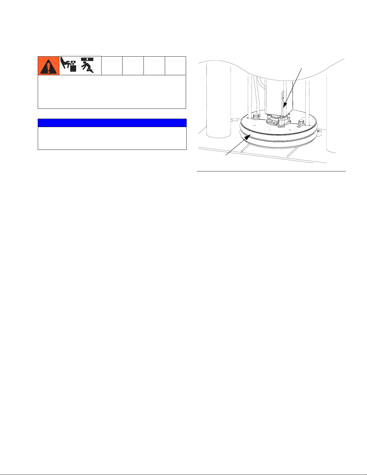
4. Remove bleed stick from platen. Push bleed stick
through bleed relieve port (T) to remove material
residue. See F
5. Remove platen covers. See F
IG
. 30.
IG
. 30.
Remove and Reinstall Platen Wipers
Refer to Supply Units Repair-Parts manual for instructions.
70
49
Bleed
Stick
T
r_wm2179_313296_6a
43
48
a. Remove platen cover fasteners (70) or nuts
(309).
For 55 gallon platen (D200 3 in. and D200s 6.5
b.
in. supply systems):
Remove both platen covers
(49) and ground wire from platen.
For smaller platens (D60 3 in. supply systems):
Disconnect pump for the platen; see Discon-
nect Pump from Platen, page 50. Remove
screws (323) from upper heater plate (320).
Remove upper heater plate.
6. Remove any excess fluid. Use a soft wire brush on
heater coils (48) or heater (319). See F
IG
. 30.
7. Inspect platen heater blocks (43 or 320) or heater
(48 or 319) for burn or melt spots. Replace platen
heater blocks or heater if necessary. See F
IG
. 30.
8. Check for loose connections and damaged wires.
9. Follow steps in reverse order to reassemble platen.
309
Bleed
Stick
T
FIG. 30: Remove Platen Covers and Heaters
309
323
320
319
NOTE: Torque platen cover fasteners (70) to 60 +/10 in-lbs (6.8 +/- 1.1 N•m) for 55 gallon platen.
Torque nuts (309) to 45 +/- 5 in-lbs (5.1 +/- 0.6 N•m)
for smaller platens.
313296J 33
Page 34

Maintenance
Electrical Enclosure
1. Turn the main disconnect on the electrical control
panel door to the OFF position to disconnect power.
Power is still connected to the power line filter (459)
even after the main disconnect is open. Avoid contact with the power line filter.
2. Open door of electrical enclosure.
459
419
Check Ground Fault Circuit Interrupter
1. With electrical enclosure door still open, switch main
disconnect (421) back on.
Have a qualified electrician restore power to main
disconnect while electrical enclosure door is open.
2. Press Test button on ground fault circuit interrupter
(419). The blue switch should flip to the middle or
opposite side.
NOTE: Do not perform this test while the system is
in operation.
3. Press blue switch back into place to reset breaker.
419
421
F
IG
. 31: Inside View of Electrical Enclosure
3. Check for damaged or loose wires. Check connections from cable track.
F
IG
. 32: Ground Fault Circuit Interrupter
4. Switch main disconnect off.
34 313296J
Page 35

Maintenance
Pump Heaters
1. Turn the main disconnect on the electrical control
panel door to the OFF position to disconnect power.
2. Remove four screws (80 or 257) from back pump
shroud (52 or 234).
D200 Shown
80 or 257
4. Check for damaged wires and connections.
5. Ensure heaters (44 or 227) are secure so they cannot rotate on pump.
D200 Shown
44 or 227
F
IG
. 34: Pump Heaters
F
IG
. 33: Remove Pump Shroud
3. Remove pump heater front shroud (51 or 233).
313296J 35
Page 36

Alarms
Alarms
Warm Melt alarms alert you to a problem and help pre-
Diagnose Alarms
vent system shutdown or application errors. If an alarm
occurs, operation may stop and the following occurs.
See Alarm Codes and Troubleshooting, page 36, for
causes and solutions to each alarm code.
• Light tower indication changes (if equipped)
• Status bar on the display shows the alarm description
Clear Alarms
Alarms are cleared by the solution(s) listed in the following table or from the screen in which they appear. Refer
to Alarm Codes and Troubleshooting, page 36, for
details.
Alarm Codes and Troubleshooting
Alarm
Code Alarm Problem Cause Solution Clear Alarm
Fluid Control Module
CB1X A - Communication Error -
Ram A Not Found
CB2X B - Communication Error -
Ram B Not Found
B61X
B62X
Crossover Error (Ram A)
Crossover Error (Ram B)
Ram cannot communicate with
FCM A.
Ram cannot communicate with
FCM B.
Inactive ram has a Not Primed
alarm.
There is a Runaway alarm Correct runaway condition
There is a Drum Empty alarm. Replace empty drum with
Verify that power is supplied.
Check that CAN cables are
connected.
Verify that selector switch
is set correctly.
Replace FCM A.
Verify that power is supplied.
Check that CAN cables are
connected.
Verify that selector switch
is set correctly.
Replace FCM B
Set inactive ram to Prime
mode to automatically clear
alarm.
and clear alarm on Status
screen 1.
full drum to clear.
Alarm automatically
cleared by solution.
Alarm automatically
cleared by solution.
Cleared from Ram Alarm
screen. See Appendix A -
User Interface Display,
page 93.
36 313296J
Page 37

Alarm
Code Alarm Problem Cause Solution Clear Alarm
Fluid Control Module (continued)
DA1X
DA2X
L11X
L12X
DB1X
DB2X
WJ1X
WJ2X
DK1X
DK2X
L21X
L22X
WK1X
WK2X
ML1X
ML2X
MA1X
MA2X
Pump Runaway A
Pump Runaway B
A - Drum Empty
B - Drum Empty
A - Not Primed
B - Not Primed
A - Air Solenoid Disconnected
B - Air Solenoid Disconnected
A - Air Motor Sensor Error
B - Air Motor Sensor Error
A - Drum Low Deviation
B - Drum Low Deviation
A - Fluid Solenoid Disconnected Deviation
B - Fluid Solenoid Disconnected Deviation
A - Rebuild Platen Seals
B - Rebuild Platen Seals
A - Rebuild Pump
B - Rebuild Pump
Pump is running faster than
set runaway limit due to:
•
Increased air pressure.
•
Increased fluid output.
•
Exhausted fluid supply.
•
Open fitting, hose, drain,
or bleed valve.
Drum empty sensor has been
activated.
The pump is not primed. Set ram to Prime mode to
Solenoid unplugged. Check that solenoid cable
Damaged solenoid / wires. Inspect solenoid wires for
System has seen multiple up
strokes without a down stroke,
or multiple down strokes without an up stroke.
Damaged or disconnected air
motor sensors.
Drum low sensor has been
activated.
Solenoid unplugged. Check that solenoid cable
Damaged solenoid wires. Inspect solenoid cable for
Counter has reached programmed platen maintenance
interval.
Counter has reached programmed pump maintenance
interval.
Correct runaway condition
and clear alarm.
Replace empty drum with
full drum to clear.
automatically clear alarm,
or manually clear alarm
from Ram Alarm screen.
is connected.
damage.
See air motor manual. Cleared from Ram Alarm
Check that air motor sensors are connected.
Inspect air motor sensor
harness for damage.
Replace empty drum with
full drum to clear.
is connected.
damage.
Perform platen maintenance; see Supply Systems Repair-Parts manual.
Perform pump maintenance. See Check-Mate
Displacement Pump manual.
Cleared from Ram Alarm
screen. See Appendix A -
User Interface Display,
page 93.
Alarm automatically
cleared by solution.
Cleared from Ram Alarm
screen or Ram Operation
screen. See Appendix A -
User Interface Display,
page 93.
Alarm automatically
cleared by solution.
Alarm automatically
cleared by solution.
screen. See Appendix A -
User Interface Display,
page 93.
Deviation automatically
cleared by solution.
Deviation automatically
cleared by solution.
Cleared from Maintenance
screen. See Appendix A -
User Interface Display,
page 93.
Cleared from Maintenance
screen. See Appendix A -
User Interface Display,
page 93.
Alarms
313296J 37
Page 38

Alarms
Alarm
Code Alarm Problem Cause Solution Clear Alarm
Fluid Control Module (continued)
DA1X
DA2X
L11X
L12X
DB1X
DB2X
WJ1X
WJ2X
DK1X
DK2X
L21X
L22X
WK1X
WK2X
ML1X
ML2X
MA1X
MA2X
Pump Runaway A
Pump Runaway B
A - Drum Empty
B - Drum Empty
A - Not Primed
B - Not Primed
A - Air Solenoid Disconnected
B - Air Solenoid Disconnected
A - Air Motor Sensor Error
B - Air Motor Sensor Error
A - Drum Low Deviation
B - Drum Low Deviation
A - Fluid Solenoid Disconnected Deviation
B - Fluid Solenoid Disconnected Deviation
A - Rebuild Platen Seals
B - Rebuild Platen Seals
A - Rebuild Pump
B - Rebuild Pump
Pump is running faster than
set runaway limit due to:
•
Increased air pressure.
•
Increased fluid output.
•
Exhausted fluid supply.
•
Open fitting, hose, drain,
or bleed valve.
Drum empty sensor has been
activated.
The pump is not primed. Set ram to Prime mode to
Solenoid unplugged. Check that solenoid cable
Damaged solenoid / wires. Inspect solenoid wires for
System has seen multiple up
strokes without a down stroke,
or multiple down strokes without an up stroke.
Damaged or disconnected air
motor sensors.
Drum low sensor has been
activated.
Solenoid unplugged. Check that solenoid cable
Damaged solenoid wires. Inspect solenoid cable for
Counter has reached programmed platen maintenance
interval.
Counter has reached programmed pump maintenance
interval.
Correct runaway condition
and clear alarm.
Replace empty drum with
full drum to clear.
automatically clear alarm,
or manually clear alarm
from Ram Alarm screen.
is connected.
damage.
See air motor manual. Cleared from Ram Alarm
Check that air motor sensors are connected.
Inspect air motor sensor
harness for damage.
Replace empty drum with
full drum to clear.
is connected.
damage.
Perform platen maintenance; see Supply Systems Repair-Parts manual.
Perform pump maintenance. See Check-Mate
Displacement Pump manual.
Cleared from Ram Alarm
screen. See Appendix A -
User Interface Display,
page 93.
Alarm automatically
cleared by solution.
Cleared from Ram Alarm
screen or Ram Operation
screen. See Appendix A -
User Interface Display,
page 93.
Alarm automatically
cleared by solution.
Alarm automatically
cleared by solution.
screen. See Appendix A -
User Interface Display,
page 93.
Deviation automatically
cleared by solution.
Deviation automatically
cleared by solution.
Cleared from Maintenance
screen. See Appendix A -
User Interface Display,
page 93.
Cleared from Maintenance
screen. See Appendix A -
User Interface Display,
page 93.
38 313296J
Page 39

Alarm
Code Alarm Problem Cause Solution Clear Alarm
Fluid Control Module (continued)
DD1X
DD2X
A - Pump Diving
B - Pump Diving
Pump leak. Worn valve or packings.
See Check-Mate Displacement Pump manual.
Ram air pressure set too low. Increase air pressure to
ram until diving stops.
Material flow rate exceeds
ability of ram to feed pump.
Temperature Control Modules
Decrease pump air pressure to slow cycle rate.
Decrease pressure until
diving stops.
Cleared from Ram Alarm
screen. See Appendix A -
User Interface Display,
page 93.
The last digit in the temperature control module alarm codes identify the heat zone.
T3A1
T3A2
T3A3
T3A4
T3A5
T3A6
T3A7
T3A8
T3A9
T3A10
T3A11
T3A12
T2A1
T2A2
T2A3
T2A4
T2A5
T2A6
T2A7
T2A8
T2A9
T2A10
T2A11
T2A12
Alarm Above Setpoint
Deviation Above Setpoint
Deviation Below Setpoint Tripped circuit breaker. Visually check circuit
RTD on wrong module. Verify RTD wire and heater
power cord is attached to
correct heat module.
Shorted module. Replace module.
breaker for a tripped condition.
Low power. Measure voltage across
input terminals on power
line filter. Voltage should
measure between 190 and
250 Vac.
Cable unplugged/loose wire. Check for loose or discon-
nected wires and plugs.
Circuit breaker not set for L2
and L3.
Bad heaters. Measure resistance of
GFCI has been tripped. Visually check GFCI for a
Customer supplied main circuit
breaker tripped.
Visually check circuit
breaker for proper setting
of L2 and L3.
heater.
tripped condition.
Measure voltage across the
disconnect switch. Voltage
should measure between
190 and 275 Vac.
Cleared from Heat Run
screen. See Heat Run
Screen, page 101.
Cleared from Heat Run
screen. See Heat Run
Screen, page 101.
Alarms
313296J 39
Page 40

Alarms
Alarm
Code Alarm Problem Cause Solution Clear Alarm
Temperature Control Modules (continued)
T6A1
T6A2
T6A3
T6A4
T6A5
T6A6
T6A7
T6A8
T6A9
T6A10
T6A11
T6A12
A4A1
A4A2
A4A3
A4A4
A4A5
A4A6
A4A7
A4A8
A4A9
A4A10
A4A11
A4A12
No Temp Rise Tripped circuit breaker. Visually check circuit
breaker for a tripped condition.
Low power. Measure voltage across
input terminals on power
line filter. Voltage should
measure between 190 and
250 Vac
Cable unplugged/loose wire. Check for loose or discon-
nected wires and plugs.
Circuit breaker not set for L2
and L3.
Bad heater(s). Measure resistance of
GFCI has been tripped. Visually check GFCI for a
Customer supplied main circuit
breaker tripped.
Over current Bad heaters. Measure resistance of
Wrong zone type. Ensure zone is set for type
High voltage. Measure voltage across the
Shorted module. If temperature rises for a
Visually check circuit
breaker for proper setting
of L2 and L3.
heater(s).
tripped condition.
Measure voltage across the
disconnect switch. Voltage
should measure between
190 and 275 Vac.
heater.
of hardware connected to
it.
disconnect switch. Voltage
should measure between
190 and 275 Vac.
zone that has been disabled, replace heat module.
Cleared from Heat Run
screen. See Heat Run
Screen, page 101.
Cleared from Heat Run
screen. See Heat Run
Screen, page 101.
40 313296J
Page 41

Alarm
Code Alarm Problem Cause Solution Clear Alarm
Temperature Control Modules (continued)
A1A1
A1A2
A1A3
A1A4
A1A5
A1A6
A1A7
A1A8
A1A9
A1A10
A1A11
A1A12
A7A1
A7A2
A7A3
A7A4
A7A5
A7A6
A7A7
A7A8
A7A9
A7A10
A7A11
A7A12
T6A1
T6A2
T6A3
T6A4
T6A5
T6A6
T6A7
T6A8
T6A9
T6A10
T6A11
T6A12
Undercurrent Tripped circuit breaker. Visually check circuit
breaker for a tripped condition.
Over temperature protection is
activated.
Low power. Measure voltage across
Cable unplugged/loose wire. Check for loose or discon-
Circuit breaker not set for L2
and L3.
Bad heaters. Measure resistance of
GFCI has been tripped. Visually check GFCI for a
Customer supplied main circuit
breaker tripped.
Wrong zone type. Ensure zone is set for type
Unexpected Current Shorted module. If temperature rises for a
Invalid RTD Reading Bad RTD. Measure resistance of RTD
Bad RTD connection/loose
wire.
Component not plugged in. Ensure a component is
Allow zone to cool down.
input terminals on power
line filter. Voltage should
measure between 190 and
250 Vac.
nected wires and plugs.
Visually check circuit
breaker for proper setting
of L2 and L3.
heater.
tripped condition.
Measure voltage across the
disconnect switch. Voltage
should measure between
190 and 250 Vac.
of hardware connected to
it.
zone that has been disabled, replace heat module.
and verify it is within valid
range.
Check for loose or disconnected wires and plugs.
plugged into zone reporting error. If nothing is
plugged in, disable zone.
Cleared from Heat Run
screen. See Heat Run
Screen, page 101.
Cleared from Heat Run
screen. See Heat Run
Screen, page 101.
Cleared from Heat Run
screen. See Heat Run
Screen, page 101.
Alarms
313296J 41
Page 42

Alarms
Alarm
Code Alarm Problem Cause Solution Clear Alarm
T4C1
T4C2
T4C3
T4C4
T4C5
T4C6
T4C7
T4C8
T4C9
T4C10
T4C11
T4C12
V4M1
V4M2
V4M3
V4M4
V4M5
V4M6
V4M7
V4M8
V4M9
V4M10
V4M11
V4M12
V1M1
V1M2
V1M3
V1M4
V1M5
V1M6
V1M7
V1M8
V1M9
V1M10
V1M11
V1M12
V4I1
V4I2
V4I3
V4I4
V4I5
V4I6
V4I7
V4I8
V4I9
V4I10
V4I11
V4I12
PCB Overtemperature Overheated Temperature
Control Module.
High Line Voltage Incoming line voltage is too
high.
No Line Voltage
Low Line Voltage
High DC Voltage Faulty DC power supply. Measure that DC supply
Tripped circuit breaker. Visually check circuit
GFCI has been tripped. Visually check GFCI for a
Cable unplugged/loose wire. Check for loose or discon-
Turn heat zone off. Wait a
few minutes. If the condition does not clear on its
own, replace heater module.
Measure voltage across
disconnect switch. Voltage
should measure between
190 and 250 Vac.
breaker for a tripped condition.
tripped condition.
nected wires and plugs.
output is 24V. If not,
replace supply.
Cleared from Heat Run
screen. See Heat Run
Screen, page 101.
Cleared from Heat Run
screen. See Heat Run
Screen, page 101.
Cleared from Heat Run
screen. See Heat Run
Screen, page 101.
Cleared from Heat Run
screen. See Heat Run
Screen, page 101.
42 313296J
Page 43

Alarm
Code Alarm Problem Cause Solution Clear Alarm
Temperature Control Modules (continued)
V1I1
V1I2
V1I3
V1I4
V1I5
V1I6
V1I7
V1I8
V1I9
V1I10
V1I11
V1I12
A4C1
A4C2
A4C3
A4C4
A4C5
A4C6
A4C7
A4C8
A4C9
A4C10
A4C11
A4C12
A1C1
A1C2
A1C3
A1C4
A1C5
A1C6
A1C7
A1C8
A1C9
A1C10
A1C11
A1C12
A7C1
A7C2
A7C3
A7C4
A7C5
A7C6
A7C7
A7C8
A7C9
A7C10
A7C11
A7C12
Low DC Voltage Faulty DC power supply. Measure that DC supply
output is 24V. If not,
replace supply.
Broken Temperature Control
Module.
High Contactor Current Broken contactor. Replace contactor. Cleared from Heat Run
Low Contactor Current Broken contactor. Replace contactor. Cleared from Heat Run
Disconnected or loose wire. Verify cable 15W902 from
Broken Temperature Control
Module.
Unexpected Contactor Current
Broken Temperature Control
Module.
If DC supply is supplying
24V when disconnected
from system, check which
module is causing short.
Check this by connecting
one module at a time and
then measuring for 24V.
High Power Temperature
Control Module is connected correctly.
Verify there is 24V between
both wires on 15W902. If
there is not 24V, replace
High Power Temperature
Control Module.
Turn heat zone for platen
off. If there is still 24V
across wires on 15W902,
replace Temperature Control Module.
Cleared from Heat Run
screen. See Heat Run
Screen, page 101.
screen. See Heat Run
Screen, page 101.
screen. See Heat Run
Screen, page 101.
Cleared from Heat Run
screen. See Heat Run
Screen, page 101.
Alarms
313296J 43
Page 44

Troubleshooting
Troubleshooting
1. Follow Pressure Relief Procedure, page 28,
before disassembling any part of the warm melt
supply system.
NOTE: Troubleshooting covered in this manual is
specific to warm melt heat functions. Refer to Supply Systems Repair-Parts manual and/or Tandem
Supply Systems Repair-Parts manual for ram troubleshooting. Refer to Check-Mate Pump Packages
manual for pump troubleshooting.
Problem Cause Verification Solution
No power. Customer supplied main
circuit breaker tripped.
GFCI has been tripped. Visually check GFCI for a
No graphics on screen. No graphics are shown on
display screen.
2. Disconnect all power to the warm melt supply system before repairing.
3. Check all possible problems before disassembling
any part of the warm melt supply system.
Measure voltage across
disconnect switch; voltage
should measure between
190 and 250 Vac.
tripped condition.
Verify green LED on bottom
of display is illuminated.
3
24 Rtn
2
24 Vdc+
GCA cable end
Determine cause of the
tripped circuit breaker.
Then repair fault and reset
main circuit breaker.
Determine fault that caused
GFCI to trip. Then repair
fault and reset GFCI.
If green LED is not illuminated:
1. Check for DC power on
the GCA cable at the
display. Replace faulty
cable/component.
2. Replace faulty display
module.
If green LED is illuminated,
check red LED. If red LED
is illuminated, replace display module.
Backlight does not power
up.
44 313296J
Can see display, but backlight is not illuminated when
a button is pressed.
Replace display module.
Page 45

Troubleshooting
Problem Cause Verification Solution
No heat. Tripped circuit breaker. Visually check circuit
breaker for a tripped condition.
Low power. Measure voltage across
terminals 2T1 and 4T2 on
main disconnect. Voltage
should measure between
190 and 275 Vac.
Cable unplugged/loose
wire.
Check for loose or disconnected wires and plugs.
GFCI tripped. Visually check GFCI for a
tripped condition.
Zone not enabled. Verify zone is enabled on
Heat Run screen.
Incorrect temperature set
point.
Verify zone has a correct
temperature setting on
Heat Run screen.
Bad heater. Measure resistance of
heater.
Determine cause of tripped
circuit breaker. Then repair
fault and reset main circuit
breaker.
1. If voltage is lower than
expected, use electrical
schematic to locate
faulty wiring or connection.
2. Have a qualified electrician service electrical
components.
Attach plug/wire.
Determine fault that caused
GFCI to trip. Repair fault,
and reset GFCI.
Enter Setup screen and
enable correct zone.
Enter Setup and enter correct temperature.
1. Unplug suspected
heater zone from
heater module.
Contactor not closing. Turn on heat for zone A1 or
B1and ensure contactor
closes.
2. Follow Heater Resis-
tance Checks, page
22.
3. If resistance is outside
allowable value,
replace heater(s).
1. Verify cable 15W902
from the high power
TCM is connected correctly.
2. Verify that there are no
other error conditions
that would prevent
heater from starting.
3. Verify there is 24 Vdc
between 2 wires on
15W902. If not, replace
high power TCM. See
Alarms, page 36.
4. Replace contactor.
313296J 45
Page 46

Troubleshooting
Problem Cause Verification Solution
Missing module. Modules not on network. Verify attached modules
through Advanced Setup
screens 4 and 5.
Cable disconnected. Verify all green LEDs are
illuminated and yellow
LEDs are flashing.
Module with wrong rotary
switch setting.
Verify rotary switch is set
correctly.
Enter Setup screen and
scroll to Advanced Setup
screens 4 and 5. These
screens lists all components corresponding software revision number on
network.
Reconnect/replace faulty
cable.
1. Remove power from
unit.
2. Remove access cover
and visually check
rotary switch setting.
3. If incorrect, set to correct setting. See
Upgrade Temperature Control Module
Software, page 56,
and Upgrade FCM
Software, page 59, for
selector switch locations.
Heating is slow. Heater defective. Measure resistance of
heater.
Low power. Measure voltage across
terminals 2T1 and 4T2 on
main disconnect. Voltage
should measure between
190 and 275 Vac.
Heating over shoots. RTD on wrong module. Verify for given zone that
temperature does not
increase when zone is dis-
Shorted module. Replace module.
Does not crossover. Alternate ram has an empty
abled.
Verify ram has material. Replace empty drum.
sensor activated.
Alternate pump is not
primed.
Alternate pump has an
active alarm.
Verify alternate ram is
ready to run.
See Alarm Codes and
Troubleshooting, page
36.
4. Replace access cover.
Follow Heater Resistance
Checks, page 22.
1. If voltage is lower than
expected, use electrical
schematic to locate
faulty wiring or connection.
2. Have a qualified electrician service electrical
components.
Verify RTD wire or heater
power cord is attached to
correct heat module.
Prime pump.
See Alarm Codes and
Troubleshooting, page
36.
46 313296J
Page 47

Repair
To reduce the risk of serious injury, follow the Pressure Relief Procedure and the Load Material pro-
cedure prior to performing repair procedures.
Air Motor
Remove Air Motor
Remove junction box.
For 55 gallon platen (D200 and D200s supply systems):
Remove two screws (61) securing junction box to air
motor. Remove junction box and temporarily secure to
platen rod.
Repair
For smaller platens (D60 3 in. supply systems):
Remove junction box. Remove screws (278) from junction box (255), and remove cover (271). Remove junction box from bracket (258).
61
96
90, 91
F
IG
. 35: Remove D200 and D200s Junction Box
42
71
12
258
IG
. 36: Remove D60 Junction Box
F
3. See Disconnect Displacement Pump in
Check-Mate Pump Packages manual.
To reduce the risk of serious injury or damage to
equipment, make sure the main disconnect is off
before continuing with this procedure.
4. See Supply System repair manual for air motor
removal instructions.
255
271
278
313296J 47
Page 48

Repair
Install Air Motor
1. See Supply System repair manual for air motor
installation instructions.
2. Reinstall junction box.
For 55 gallon platen (D200 and D200s supply systems):
Remove junction box from platen rod. Reinstall junction box to air motor using move two
screws (61). See F
IG
. 35.
For smaller platens (D60 3 in. supply systems):
Reinstall junction box (255) onto bracket (258). Use
screws (278) to attach cover (271). See F
IG
. 36.
Displacement Pump
Remove Displacement Pump
This procedure must be done while the system is still
warm. The material and equipment may still be hot.
shrouds (51, 52), pump heaters (44), and RTD sensor (46).
51
44
46
44
r_wm2179_313296_7a
52
FIG. 37: D200 and D200s Pump Heater Shrouds
4. Raise air motor. Loosen nut (HB) under ram bar and
thread it down the threaded rod (HC) to the lift ring
adapter (HD) holding the motor. Use wrench on nut
(HA) on top of ram bar to raise air motor.
HC
Refer to your Check-Mate Displacement Pump manual
to repair the displacement pump.
If the air motor does not require servicing, leave it
attached to its mounting. If the air motor does need to
be removed, see Remove Air Motor, page 47.
D200 and D200s Supply Systems
1. Disconnect air hose and ground wire from air motor.
2. See Disconnect Displacement Pump in
Check-Mate Pump Packages manual.
3. Follow steps 1- 4 of Replace Platen Heaters and
Sensor section, page 52, to remove pump heater
HA
HD
HB
TI10648A
IG
. 38: Raise Air Motor
F
5. See Disconnect Pump from Platen, page 50, to
disconnect the displacement pump from the platen.
6. Use two people to carefully lift out the displacement
pump. Service displacement pump as needed. See
Check-Mate Displacement Pump manual for
instructions.
48 313296J
Page 49

Repair
D60 Supply System
1. Disconnect air hose and ground wire from air motor.
2. See Disconnect Displacement Pump in
Check-Mate Pump Packages manual.
3. Follow steps 1- 4 of Replace Platen Heaters and
Sensor section, page 52, to remove pump heater
shrouds (233, 234), pump heaters (227), and RTD
sensor (229).
227
229
227
r_wm29yy_313296b_3
233
Install Displacement Pump
D200 and D200s Supply Systems
1. Install displacement pump on platen. See Connect
Pump to Platen, page 51.
2. Lower air motor. Use wrench on nut (EA) to lower
air motor.
3. Reinstall pump heater shrouds (51, 52). Secure with
screws (80).
4. See Reconnect Displacement Pump in
Check-Mate Pump Packages manual.
5. Reconnect air hose and ground wire to air motor.
F
IG
. 39: D60 Pump Heater Shrouds
4. See to Disconnect Pump from Platen on page 50
to disconnect displacement pump from platen.
5. Raise ram assembly to lift air motor away from displacement pump.
6. Remove displacement pump, and service as
needed. See Check-Mate Displacement Pump
manual.
TI10515A
F
IG
. 40: Reconnect Air Hose and Ground Wire
D60 Supply System
1. Raise ram to install displacement pump to platen.
2. Connect displacement pump to platen. See Con-
nect Pump to Platen, page 51.
3. Reinstall pump heater shrouds (233, 234). Secure
with screws (257).
4. See Reconnect Displacement Pump in
Check-Mate Pump Packages manual.
5. Reconnect air hose and ground wire to air motor.
313296J 49
Page 50

Repair
Disconnect Pump from Platen
The pump is mounted to the platens by mounting Kit
255392.
55 Gallon Platen
1. Disconnect displacement pump from air motor. See
Check-Mate Pump Packages manual.
2. Raise air motor. See Remove Displacement
Pump, page 48.
3. Remove four screws (103a) and four clamps (103b).
103a
103b
20, 30, and 60 Liter Platens
1. Disconnect displacement pump from air motor. See
Check-Mate Pump Packages manual.
2. Raise air motor. See Remove Displacement
Pump, page 48.
3. Remove screws (308) from platen.
308
103c
FIG. 41: 55 Gallon Mounting Kit
4. Use two people to carefully lift pump from platen.
5. Inspect o-ring (103c) for damage. Replace o-ring if
necessary.
F
IG
. 42: 20, 30, 60 Liter Mounting
4. Use two people to carefully lift pump from platen. If
using a pump with an intake adapter, remove
screws, adapter, and o-rings from pump inlet.
5. Inspect o-ring for damage. Replace o-ring if necessary.
50 313296J
Page 51

Repair
Connect Pump to Platen
55 Gallon Platen
1. Use two people to set pump onto platen.
2. Secure pump to platen with screws (103a) and
clamps (103b). See F
3. Lower air motor.
4. See Reconnect Displacement Pump in
Check-Mate Pump Packages manual.
20, 30, and 60 Liter Platen
NOTE: Before installing a 20, 30, or 60 liter platen to
a pump with an intake adapter, install adapter and
o-ring.
1. Place o-ring on pump intake. See F
IG
. 41.
IG
. 42.
Replace Pump Heaters
1. Turn off main disconnect.
2. Remove screws (80 or 257) from back pump heater
shroud (52 or 234).
D200 Shown
52
or
80 or 257
234
2. Use two people to set pump onto platen.
3. Secure pump to platen with screws (308).
4. Lower air motor.
5. See Reconnect Displacement Pump in
Check-Mate Pump Packages manual.
FIG. 43: Remove Pump Shroud
3. Remove ground wires.
4. Remove pump heater front shroud (51 or 233).
313296J 51
Page 52

Repair
5. Remove pump heater bands (44 or 227):
a. Remove screws from both pump heaters.
b. Pry heater bands apart and remove from pump.
c. Disconnect wires from heater bands. Inspect
wires for damage, and replace with new wires
(included with pump heaters) if necessary. See
Electrical Schematics, page 61.
d. Remove RTD sensor (46 or 229). Loosen screw
on sensor support (45 or 228) and slide RTD
out.
44 or 227
45 or 228
46 or 229,
110
44 or 227
Replace Platen Heaters and Sensor
55 Gallon Platen Heater and Sensor
1. Turn off main disconnect.
2. Remove both platen cover fasteners (70).
3. Remove both platen covers (49) and ground wire
from platen.
70
49
59
11
43
ti17720a
F
IG
. 44: Remove Pump Heaters
6. Install new pump heater bands and secure with
screws.
NOTE: To ease pump heater band installation, first
install heater bands on middle of displacement
pump. Then slide heater band up or down into correct location.
7. Reinstall RTD sensor and tighten screw on sensor
support.
NOTE: Ensure RTD is flush to pump before tightening screw.
8. Reinstall pump heater front shroud.
9. Reinstall ground wires.
10. Reinstall back pump heater shroud, and secure with
screws.
64
109
58
82
FIG. 45: Replace Platen Heaters and RTD Sensor
4. Remove platen heater blocks (43).
a. Use a hex wrench to remove three nuts (59)
and washers (11, 64) from each heater block.
b. Remove screws (12) from junction box cover
(96). Loosen strain relief nut (91), and remove
junction box cover.
c. Disconnect four platen heater wires (labeled A
dn B) and RTD sensor connector in the terminal
box. See Electrical Schematics, page 61.
ti18061a
52 313296J
Page 53

d. Remove screws (58) and washers (82).
Remove platen heater blocks (43) and RTD
sensor (46).
5. Install new platen heaters and RTD sensor. Secure
RTD sensor with screw and washer. Secure platen
heater blocks with nuts and washers.
Repair
324
323
6. Label platen heater wires A and B as shown on
page 64. Reroute platen heater wires and platen
RTD sensor through the conduit to the junction box.
Reconnect the four wires to the appropriate terminal
block A and B. Reconnect the platen RTD sensor.
7. Reinstall junction box cover. Secure with screws
and tighten strain relief nut.
8. Reconnect ground wire, and install platen covers.
Secure platen covers with fasteners. Torque platen
cover fasteners to 60 in-lbs +/- 10 in-lbs (6.8 +/- 1.1
N•m)
9. Reconnect displacement pump using screws and
clamps.
20, 30, and 60 Liter Platen Heater
1. Disconnect pump from platen.
2. Remove platen heater block (320).
a. Remove screws (278) from junction box cover
(271), and remove junction box cover. See page
86.
Air Fitting
Assembly
ti17717b
F
IG
. 46: Replace Platen Heaters
3. Remove platen heater (319).
a. Disconnect two platen heater wires (labeled A
and B) in the terminal box. See D60 Junction
Box Schematic, page 71.
b. Remove platen and heater (319).
320
319
318
309
b. Remove strain relief nut (265) from junction box
to allow space for wires. See page 86.
4. Install new platen heater (319) to lower heater plate
(318). Install upper heater plate (320). Reconnect
ground wire, and secure with screws.
c. Remove air fitting assembly from platen.
5. Label platen heater wires A and B as shown on
d. Remove nuts (309) from the heat shield guard
(324).
page page 70. Reroute platen heater wires through
the conduit to the junction box. Reconnect the two
wires to the appropriate terminal block A and B.
e. Remove screws (323) from upper heater plate
(320). Remove upper heater plate and ground
6. Reinstall heat shield guard. Secure with nuts.
Torque nuts to 45 +/- 5 in-lbs (5.1 +/- 0.6 N•m).
wire.
7. Reconnect displacement pump using screws and
clamps.
8. Reinstall junction box cover and strain relief nut.
Secure cover with screws.
313296J 53
Page 54

Repair
Replace Platen Wipers
Refer to Supply Systems Repair-Parts manual for
instructions.
Replace Ram Piston Rod Seals
1. Support electrical enclosure (13 or 14) using a loop
and a hoist.
2. Remove screws from bracket (50 or 232) connecting electrical enclosure (13 or 14) to ram piston rod
and cable track (42, if applicable).
42
13 or 14
50 or 232
FIG. 47: Replace Rod Seals
3.
For 55 gallon platen (D200 and D200s supply systems):
(50) to side.
For smaller platens (D60 supply systems):
bracket (232).
Gently move cable track (42) and bracket
Remove
4. See Supply Systems Repair-Parts manual for
replacement instructions.
5. Follow steps in reverse order to reinstall bracket,
cable track (if applicable), and the electrical enclosure.
54 313296J
Page 55

Repair
Electrical Enclosure
Prior to repairing any component of the electrical enclosure (13 or 14), turn the main disconnect on the electrical control panel door to the OFF position to disconnect
power.
Replace Low Power Temperature Control
Module(s)
1. Open enclosure door (402). Disconnect the follow-
Power is still connected to the power line filter (459)
even after the main disconnect is open. Avoid contact with the power line filter.
ing cables from low power TCM (408):
• incoming power supply cable (430)
• outbound power supply cable (see F
• RTD cable
IG
. 49)
408
Outbound
Power
RTD
411
Outbound
Power
RTD
FIG. 49: Back View of Electrical Enclosure
2. Loosen both captive screws (409) holding low
power TCM (408) to base (407); remove low power
TCM. See F
3. Follow steps in reverse order to install new low
power TCM.
4. Upload the correct TCM software for the system.
See Upgrade Temperature Control Module Soft-
ware, page 56, for instructions.
IG
. 48.
459
Captive
Screw
430
408
Captive
Screw
411
431
429
428
432
F
IG
. 48: Internal View of Electrical Enclosure
313296J 55
Page 56

Repair
Replace Base
1. Remove low power TCM. See Replace Low Power
Temperature Control Module(s).
2. Disconnect two CAN cables from base (407).
3. Remove four screws (409) and ground screw (410)
from base.
4. Replace with new base and secure with screws.
5. Reconnect two CAN cables to base.
6. Set selector switch to:
• “0” for TCM labeled “2” on Ram A
• “1” for TCM labeled “3” on Ram A
• “2” for TCM labeled “4” on Ram A
• “5” for TCM labeled “2” on Ram B
• “6” for TCM labeled “3” on Ram B
• “7” for TCM labeled “4” on Ram B
Selector
Switch
TI12361a
IG
. 50: Set Selector Switch
F
7. Reinstall low power TCM. See Replace Low Power
Temperature Control Module(s).
NOTE: Reuse brackets (412, 413) to install new high
power TCM.
6. Upload the correct TCM software from kit 16C027.
See Upgrade Temperature Control Module Soft-
ware, page 56, for instructions.
7. Remove cover of new high power TCM and set
selector switch to “0” for Ram A or “1” for Ram B.
Selector
Switch
TI12360a
IG
. 51: Set Selector Switch
F
Upgrade Temperature Control Module
Software
NOTE: Order kit 16C027 for an upgrade token. See
Graco Control Architecture
manual for instructions.
™
Module Programming
NOTE: Reuse brackets (412, 413) to install new high
power TCM.
Replace High Power Temperature Control
Module
1. Open enclosure door (402). Disconnect outbound
power supply and RTD cables from high power
TCM (411). See F
2. Remove electrical enclosure side panel (436). See
Electrical Enclosure Parts on page 90.
3. Disconnect all four incoming cables (432, 428, 429,
431) from high power TCM. See F
4. Remove both screws (415) that secure brackets
(412, 413) of high power TCM to electrical enclosure. Remove high power TCM. See Electrical
Enclosure Parts on page 90.
5. Follow steps in reverse order to install new high
power TCM.
IG
. 49.
IG
. 48.
56 313296J
Page 57

Repair
Replace Circuit Breakers
1. Open enclosure door (402). Disconnect wires from
circuit breaker (417, 419).
2. Push in circuit breaker tab and pull out breaker.
417
4. Remove screws (12 or 202) and washers (11 or
201) from bottom bracket (39 or 222) and side
bracket (50 or 232) of enclosure.
D200 Shown
plug
11 or 201,
12 or 202
50 or 232
13 or 14
419
417
F
IG
. 52: Circuit Breakers
3. Replace with new circuit breaker. Use tabs on bottom of breaker to select L2 and L3.
4. Snap new circuit breaker into place and reconnect
wires.
Replace Electrical Enclosure
1. Ensure power to electrical enclosure is disconnected.
2. Disconnect heater and RTD cables from each TCM.
3. Remove plug and use lift ring (not included) at top of
electrical enclosure (13 or 14).
39 or 222
F
IG
. 53: Replace Electrical Enclosure
5. Lift enclosure off and replace with new enclosure.
6. Secure new electrical enclosure to bottom and side
brackets with screws and washers.
7. Reconnect heater and RTD cables to each TCM.
8. Reconnect power to power line filter.
Have a qualified electrician reinstall main incoming
power to system and electrical enclosure.
313296J 57
Page 58

Repair
Display/User Interface
Upgrade Display Software
NOTICE
To avoid damaging circuit board, wear a grounding
strap.
NOTE: Order kit 16C027 for an upgrade token. See
™
Graco Control Architecture
manual for instructions.
Replace Display
NOTE: Order Kit 24F493 for replacement. Software
token 16C027 is required to install software before
use.
NOTICE
To avoid damaging circuit board, wear a grounding
strap.
Module Programming
1. Disconnect power.
2. Pull display (20) out of bracket (22) clips to remove
it.
3. Disconnect CAN cable(s) from display (20).
4. Replace with new display. Reconnect CAN cable(s).
5. Load the correct display software for the system.
Follow the steps in Upgrade Display Software on
page 58.
NOTE: Token is not included with display and must
be ordered separately.
58 313296J
Page 59

Replace Fluid Control Module
D
Repair
41 or 224
1. Disconnect power to system.
2. Remove front shroud (16 or 204) and back shroud
(17 or 205).
200 Shown
16 or 204
Captive
Screws
36 or
220
28 or 215
F
IG
. 55: Remove FCM
6. Replace with new FCM, and secure with screws.
7. Reconnect cables to FCM.
8. Load the correct FCM software for the system. Follow the steps in Upgrade FCM Software on page
59.
30 or
217
33 or
219
Replace Base
17 or 205
FIG. 54: Remove Shrouds
3. Disconnect all cables from FCM (36 or 220).
4. Remove access door (41 or 224).
5. Loosen both captive screws from FCM and pull
FCM off base (33 or 219).
1. Disconnect power to system.
2. Remove FCM (36 or 220). See Replace Fluid Con-
trol Module.
3. Disconnect CAN cable(s) from FCM (36 or 220).
4. Remove screws (28 or 215) and ground screw (30
or 217) from base (33 or 219). See F
5. Replace with new base, and secure with screws.
6. Reconnect CAN cable(s).
7. Set selector switch to “A” for Ram A or “B” for Ram
B. See F
8. Reinstall FCM. See Replace Fluid Control Mod-
ule.
IG
. 55.
IG
. 55.
Upgrade FCM Software
NOTE: Order kit 16C027 for an upgrade token. See
™
Graco Control Architecture
manual for instructions.
Module Programming
313296J 59
Page 60

Repair
Replace Cable Track
D200 and D200S Supply Systems Only
NOTE: Order Kit 257163 for replacement.
1. Disconnect power to system.
2. Disconnect all 10 cables from back of electrical
enclosure (13 or 14).
4. Remove screws (12) from junction box cover (96)
and junction box (78).
5. Loosen strain relief nut (90), and remove junction
box cover.
6. Disconnect all wires in junction box. Pull wires out of
strain relief.
7. Remove mounting screws (71), washer (72), and
nut (73) securing cable track assembly (42) to junction box.
42
72
73
FIG. 56: Back View of Electrical Enclosure
3. Remove screws (71) from bracket (50) that connect
cable track (42) to electrical enclosure (13 or 14)
and ram.
42
50
71
13 or 14
IG
. 57: Cable Track Bracket
F
61
71
96
91
90
F
IG
. 58: Junction Box
8. Lift out cable track assembly and cables.
9. Replace with new cable track kit. Secure new cable
track to junction box using mounting screws.
10. Run wires through strain relief and reconnect all
wires in junction box. See D200 Junction Box
Schematic, page 65.
11. Reinstall strain relief nut and junction box cover.
Secure junction box using screws.
12. Reattach cable track to bracket. Use screws to
secure bracket holding cable track to electrical
enclosure and ram.
13. Reconnect all 10 cables to back of electrical enclosure.
12
14. Reconnect power to system.
60 313296J
Page 61

Electrical Schematics
D200 Single Ram Schematic
(1) Power
(3) COM
(2) Unused
DRUM EMPTY
F
(1)
(3)
(4)
(2)
DRUM LOW or EMPTY OPTION
2
Cable Splitter
M
(1)
(4) SIGNAL
F
(2)
(3)
(1) Solenoid signal
(2) Solenoid RTN
(1)
(2)
3
(4)
(5)
P/N 121235
AIR SOLENOID
DRUM EMPTY
F
DRUM LOW and EMPTY OPTION
(2) Unused
(1) Power
(4) SIGNAL
(3) COM
DRUM LOW
(1)
(3)
(4)
(2)
Cable Splitter
M
(1)
(1) Power
(2) Unused
(1)
(2)
213
(2)
(3)
(3) COM
(3)
(4)
(4) SIGNAL
(4)
(5)
(1) Solenoid signal
F
(1)
AIR SOLENOID
(2) Solenoid RTN
(2)
Electrical Schematics
Warm Melt
Standard Ram
63A
Warm Melt Enclosure
GFCI
Line Filter
FLUID
Motor Pigtail
M
(1)
RAM A
MODULE
CONTROL
Cable 8 Pin
(2)
(3)
(4)
(5)
C/B
8 Amp
24 Vdc P/S
(2) N/C
(3) Motor Reed Up
(1) Linear Input
M
(1)
(2)
(3)
FM
(1)
(2)
(3)
(1)
(2)
(3)
MF
(1)
(1)
Sensor Reed Switch
Top Switch 1
(5) Motor Reed Com5(7) Linear Com
(4) Motor Reed Down
(6) Linear Power
(8) Drain
(4)
(5)
(6)
(7)
(4)
(5)
(6)
(7)
(4)
(5)
(6)
(7)
(2)
(3)
(4)
(2)
(3)
(4)
Top Switch 2
Bottom Switch 1
Bottom Switch 2
LPTCM
Power
Heater
3
(8)
(8)
(8)
8 Amp
Circuit
5
Heater
Power
Fluid Filter Monitor Option
Breaker
Cable
RTD
Input
2
Cable Splitter
(1)
(2)
(3)
Power (1)
Unused (2)
Common (3)
Fluid Pressure Sensor
Cable
LPTCM
7
M
Cable 15 Meter
MF
(4)
Press Signal (4)
Power
Heater
332
(1) Power
(2) Filter Inlet Press.
(3) Common
(4) Filter Outlet Press.
(1)
(2)
(3)
(4)
(5)
(1)
(2)
(3)
(4)
(1)
(2)
(3)
(4)
Fluid Pressure Sensor
8 Amp
Circuit
Breaker
Cable
5
Heater
Power
Fluid Solenoid
Depres/Recirc Option
F
Wire Harness
M
3
(5) Drain
(5) (5)
(1)
(2)
(3)
(4)
Power (1)
Unused (2)
Common (3)
Press Signal (4)
RTD
Input
(1) Signal
(1)
(1)
(2)
Drain (2)
Unused (1)
Cable
(2) Common
(GND) Unused
(2)
(3)
(3)
(4)
Signal (4)
Common (3)
Cable
AIR SOLENOID
F
M
(1)
1
Power (1)
(1) Solenoid signal
(2) Solenoid RTN
(1)
(2)
(5)
(2)
(3)
(4)
Common (3)
Low Sensor (2)
Air Solenoid (5)
Empty Sensor (4)
SHLD (1)
SHLD (1)
+24Vdc (2)
-24Vdc (3)
-24Vdc (3)
+24Vdc (2)
Ferrite Bead
CAN_L (5)
CAN_H (4)
CAN_H (4)
CAN_L (5)
Ferrite Bead
SHLD (1)
SHLD (1)
-24Vdc (3)
CAN_H (4)
CAN_L (5)
+24Vdc (2)
Module
Gateway
Gateway Option
Ferrite Bead
-24Vdc (3)
+24Vdc (2)
CAN_L (5)
CAN_H (4)
Light Tower Option
Light Tower
M
2
(1) Unused
(2) Amber
(1)
(2)
Amber (2)
Unused (1)
(3) Common
(4) Green
(3)
(4)
Green (4)
Common (3)
(5) Red
(5)
Red (5)
Fieldbus
BRAN
EM
CH
M
SW
I
T
E
DISPLAY
MODULE
LAY
I
SP
D
50A
8 Amp
Circuit
Breaker
Cable
5
LPTCM
Heater
Power
RTD
Input
Power
Heater
2
CONTACTOR
Circuit
25 Amp
Cable
Breaker
Cable
HPTCM
Cable
5
Heater
Power
DC
CONTROL
RTD
Input
Power
Heater
3
2
SHLD (1)
SHLD (1)
SHLD (1)
Cable
+24Vdc (2)
+24Vdc (2)
+24Vdc (2)
-24Vdc (3)
-24Vdc (3)
Cable
-24Vdc (3)
CAN_H (4)
CAN_L (5)
CAN_H (4)
CAN_L (5)
CAN_H (4)
CAN_L (5)
2
24 Vdc+
3
24 Rtn
Cable, Volex
J-BOX CABLE TRACK
Cable, Extension
Cable, Volex
Cable, Extension
Cable, Volex
Cable, Extension
Black
Cable,10AWG
Cable, Extension
GRN/YEL
Cable,10AWG
Cable, CAN
SHIELDED CABLE
BUSS BAR
KEY
t
HOSE
t
GUN
t
PUMP
t
PLATEN
313296J 61
Page 62

Electrical Schematics
D200 Ram A Schematic
FLUID
RAM A
MODULE
CONTROL
(2) N/C
(3) Motor Reed Up
(5) Motor Reed Com5(7) Linear Com
(1) Linear Input
(4) Motor Reed Down
(6) Linear Power
(8) Drain
M
(1)
(2)
(3)
(4)
(5)
(6)
(7)
(8)
FM
(5)
(6)
(7)
(8)
(1)
(2)
(3)
(4)
Cable 8 Pin
(5)
(6)
(7)
(8)
(1)
(2)
(3)
(4)
Fluid Filter Monitor Option
Ram “A”
Warm Melt
Motor Pigtail
MF
M
(1)
(2)
(3)
(1)
(2)
(3)
(4)
(4)
(5)
(1)
(2)
(3)
(4)
Sensor Reed Switch
Top Switch 1
Top Switch 2
Bottom Switch 1
Bottom Switch 2
Fluid Pressure Sensor
Cable Splitter
(1)
(2)
Power (1)
Unused (2)
Cable 15 Meter
(3)
(4)
Common (3)
Press Signal (4)
7
(1) Power
(2) Filter Inlet Press.
M
(1)
(2)
(1)
(2)
MF
(1)
(2)
Fluid Pressure Sensor
Depres/Recirc Option
(3) Common
(4) Filter Outlet Press.
(5) Drain
(3)
(4)
(5)
(3)
(4)
(3)
(4)
(5) (5)
(1)
(2)
Power (1)
Unused (2)
Fluid Solenoid
Wire Harness
(3)
(4)
Common (3)
Press Signal (4)
AIR SOLENOID
DRUM EMPTY
(2) Unused
(1) Power
(4) SIGNAL
(3) COM
F
(1)
(3)
(4)
(2)
DRUM LOW and EMPTY OPTION
(1) Solenoid signal
(2) Solenoid RTN
(2) Unused
(1) Power
(4) SIGNAL
(3) COM
DRUM LOW
F
(1)
(3)
(4)
(2)
(1)
(2)
Cable Splitter
213
M
(1)
(2)
(3)
(4)
(5)
“B”
To Ram
Option
|OR|
(2) Unused
(1) Power
(4) SIGNAL
(3) COM
DRUM EMPTY
F
(2)
(1)
(3)
(4)
(1) Solenoid signal
Cable Splitter
M
1
2
(1)
(2)
Power (1)
Low Sensor (2)
F
(1)
3
(5)
(3)
(4)
Common (3)
Empty Sensor (4)
(2) Solenoid RTN
AIR SOLENOID
(2)
Air Solenoid (5)
SHLD (1)
SHLD (1)
+24Vdc (2)
+24Vdc (2)
-24Vdc (3)
-24Vdc (3)
Ferrite Bead
CAN_L (5)
CAN_H (4)
CAN_H (4)
CAN_L (5)
Ferrite Bead
SHLD (1)
SHLD (1)
-24Vdc (3)
CAN_H (4)
CAN_L (5)
+24Vdc (2)
Module
Gateway
Gateway Option
Ferrite Bead
+24Vdc (2)
-24Vdc (3)
Ferrite Bead
CAN_L (5)
CAN_H (4)
Light Tower
(1) Unused
(2) Amber
(3) Common
(4) Green
(1) Signal
(2) Common
(GND) Unused
(3)
(3)
(4)
Signal (4)
Common (3)
Light Tower Option
F
(1)
(2)
M
(1)
(2)
3
Drain (2)
Unused (1)
(5) Red
(5)
M
(1)
(2)
(3)
(4)
Red (5)
2
Green (4)
Amber (2)
Unused (1)
Common (3)
Fieldbus
C
BR
EM
SW
I
H
T
M
E
DISPLAY
MODULE
AN
I
SPL
D
AY
SHLD (1)
SHLD (1)
Cable
+24Vdc (2)
+24Vdc (2)
-24Vdc (3)
-24Vdc (3)
CAN_H (4)
CAN_L (5)
CAN_H (4)
CAN_L (5)
2
24 Vdc+
3
24 Rtn
63A
GFCI
Warm Melt Enclosure
Line Filter
8 Amp
24 Vdc P/S
50A
C/B
8 Amp
Circuit
Breaker
Cable
5
LPTCM
Heater
Power
RTD
Input
Power
Heater
3
2
Cable, Volex
Cable, Extension
8 Amp
Circuit
Breaker
Cable
Cable
5
LPTCM
Heater
Power
RTD
Input
Power
Heater
332
Cable, Volex
Cable, Extension
8 Amp
Circuit
Breaker
Cable
Cable
5
LPTCM
Heater
Power
RTD
Input
Power
Heater
2
Cable, Volex
Cable, Extension
J-BOX CABLE TRACK
CONTACTOR
Circuit
25 Amp
Cable
DC
P/N 255774
Heater
3
Black
Cable,10AWG
Power
CONTROL
Breaker
5
Heater
Power
RTD
Input
2
Cable, Extension
Cable
GRN/YEL
Cable,10AWG
SHLD (1)
Cable, CAN
Cable
-24Vdc (3)
+24Vdc (2)
CAN_H (4)
CAN_L (5)
SHIELDED CABLE
BUSS BAR
Cable
HPTCM
KEY
t
HOSE
t
GUN
t
PUMP
t
PLATEN
62 313296J
Page 63

Electrical Schematics
D200 Ram B Schematic
Warm Melt
Ram “B” Option
63A
GFCI
Cable
Warm Melt Enclosure
Line Filter
J-BOX CABLE TRACK
LPTCM
Power
Heater
3
Cable, Volex
50A
CONTACTOR
Circuit
25 Amp
8 Amp
Circuit
Breaker
Cable
5
Heater
Power
RTD
Input
2
Cable, Extension
8 Amp
Circuit
LPTCM
Power
Heater
332
Cable, Volex
Heater
Breaker
5
Power
Cable
RTD
Input
Cable, Extension
Cable
t
HOSE
8 Amp
Circuit
Breaker
Heater
Cable
5
Power
RTD
Input
2
Cable, Extension
Cable
HPTCM
Cable,10AWG
Cable
LPTCM
Power
Heater
Cable, Volex
t
PUMP
Breaker
5
Heater
Power
RTD
Input
2
Cable, Extension
Cable
GRN/YEL
Cable,10AWG
SHLD (1)
-24Vdc (3)
+24Vdc (2)
CAN_H (4)
CAN_L (5)
Cable, CAN
Cable
Cable
4
DC
Control
Power
Heater
3
Black
t
PLATEN
t
GUN
DRUM LOW and EMPTY OPTION
DRUM LOW
(1)
Cable Splitter
DRUM EMPTY
(1) Power
(2) Unused
(2)
F
(3) COM
(3)
M
(1) Power
(1)
(4) SIGNAL
(4)
(1)
(2) Unused
(2)
213
(2)
(3)
(3) COM
(3)
(4)
(4) SIGNAL
(4)
F
(5)
AIR SOLENOID
(1) Solenoid signal
(2) Solenoid RTN
(1)
(2)
(2) Unused
(1) Power
(4) SIGNAL
(3) COM
DRUM EMPTY
F
(1)
(3)
(4)
(2)
(1) Solenoid signal
(2) Solenoid RTN
Cable Splitter
M
1
2
(1)
(2)
Power (1)
Low Sensor (2)
F
(1)
3
(3)
(4)
(5)
Common (3)
Air Solenoid (5)
Empty Sensor (4)
(2)
AIR SOLENOID
SHLD (1)
SHLD (1)
-24Vdc (3)
+24Vdc (2)
-24Vdc (3)
+24Vdc (2)
CAN_L (5)
CAN_H (4)
CAN_H (4)
CAN_L (5)
Ferrite Bead
Cable, CAN 15m
SHIELDED CABLE
BUSS BAR
KEY
FLUID
CONTROL
Motor Pigtail
M
(1)
RAM “B”
MODULE
Cable 8 Pin
(2)
(3)
(4)
(5)
5
M
FM
(2) N/C
(3) Motor Reed Up
(1) Linear Input
(1)
(2)
(3)
(1)
(2)
(3)
(1)
(2)
(3)
(1)
MF
(1)
Top Switch (1)
(5) Motor Reed Com
(4) Motor Reed Down
(6) Linear Power
(8) Drain
(7) Linear Com
(4)
(5)
(6)
(7)
(8)
(4)
(5)
(6)
(7)
(8)
(4)
(5)
(6)
(7)
(8)
(2)
(3)
(4)
(2)
(3)
(4)
Sensor Reed Switch
Top Switch (2)
Bottom Switch (1)
Bottom Switch (2)
Fluid Solenoid
Depress/Recirc Option
Wire Harness
M
3
F
(1) Signal
(1)
(1)
(2)
Drain (2)
Unused (1)
(2) Common
(GND) Unused
(2)
(3)
(3)
(4)
Signal (4)
Common (3)
To Ram “A”
313296J 63
Page 64

Electrical Schematics
D200 Displacement Pump and Platen Schematics
Platen
Displacement Pump
64 313296J
Page 65

D200 Junction Box Schematic
Electrical Schematics
313296J 65
Page 66

Electrical Schematics
D200 Cable Track Schematic
66 313296J
Page 67

D60 Single Ram Schematic
(2) Unused
(1) Power
(3) COM
DRUM EMPTY
F
(2)
(1)
(3)
DRUM LOW or EMPTY OPTION
2
Cable Splitter
M
(1)
(4) SIGNAL
(4)
(2)
(1) Solenoid signal
F
(1)
3
(3)
(4)
(5)
(2) Solenoid RTN
AIR SOLENOID
(2)
DRUM EMPTY
(1) Power
F
(1)
DRUM LOW and EMPTY OPTION
(2) Unused
(1) Power
(4) SIGNAL
(3) COM
DRUM LOW
(1)
(3)
(4)
(2)
Cable Splitter
M
(1)
(2) Unused
(3)
(2)
213
(2)
(3)
(3) COM
(4)
(4) SIGNAL
(4)
(5)
(1) Solenoid signal
F
(1)
AIR SOLENOID
(2) Solenoid RTN
(2)
Electrical Schematics
Motor Pigtail
Warm Melt
D60 Standard Ram
63A
GFCI
Warm Melt Enclosure
Line Filter
FLUID
CONTROL
M
(1)
(2)
8 Amp
24 Vdc P/S
RAM A
MODULE
(3)
(4)
(5)
C/B
Cable 8 Pin
(2) N/C
(3) Motor Reed Up
(1) Linear Input
M
(1)
(2)
(3)
FM
(1)
(2)
(3)
(1)
(2)
(3)
MF
(1)
(1)
Sensor Reed Switch
Top Switch 1
(5) Motor Reed Com5(7) Linear Com
(4) Motor Reed Down
(6) Linear Power
(8) Drain
(4)
(5)
(6)
(7)
(5)
(6)
(7)
(4)
(5)
(6)
(7)
(4)
(2)
(3)
(4)
(2)
(3)
(4)
Top Switch 2
Bottom Switch 1
Bottom Switch 2
LPTCM
Power
Heater
3
(8)
(8)
(8)
8 Amp
Circuit
5
Heater
Power
Fluid Filter Monitor Option
Breaker
Cable
RTD
Input
2
Cable Splitter
(1)
(2)
(3)
Power (1)
Unused (2)
Common (3)
Fluid Pressure Sensor
Cable
LPTCM
7
M
Cable 15 Meter
MF
(4)
Press Signal (4)
Power
Heater
332
(1) Power
(2) Filter Inlet Press.
(3) Common
(4) Filter Outlet Press.
(1)
(2)
(3)
(4)
(5)
(1)
(2)
(3)
(4)
(1)
(2)
(3)
(4)
Fluid Pressure Sensor
8 Amp
Circuit
Breaker
Cable
5
Heater
Power
Fluid Solenoid
Depres/Recirc Option
F
Wire Harness
M
3
(5) Drain
(5) (5)
(1)
(2)
(3)
(4)
Power (1)
Unused (2)
Common (3)
Press Signal (4)
RTD
Input
(1) Signal
(1)
(1)
(2)
Drain (2)
Unused (1)
Cable
(2) Common
(GND) Unused
(2)
(3)
(3)
(4)
Signal (4)
Common (3)
Light Tower Option
Light Tower
M
2
(1) Unused
(1)
(2)
Amber (2)
Unused (1)
(2) Amber
(3)
Common (3)
(3) Common
(4) Green
(5) Red
(5)
(4)
Red (5)
Green (4)
AIR SOLENOID
(1) Solenoid signal
(2) Solenoid RTN
F
(1)
(2)
Cable
SHLD (1)
SHLD (1)
+24Vdc (2)
-24Vdc (3)
-24Vdc (3)
+24Vdc (2)
Ferrite Bead
CAN_L (5)
CAN_H (4)
CAN_H (4)
CAN_L (5)
Ferrite Bead
SHLD (1)
SHLD (1)
-24Vdc (3)
CAN_H (4)
CAN_L (5)
+24Vdc (2)
Module
Gateway
Gateway Option
Ferrite Bead
-24Vdc (3)
+24Vdc (2)
CAN_L (5)
CAN_H (4)
(5)
M
(1)
(2)
(3)
(4)
1
Power (1)
Common (3)
Low Sensor (2)
Air Solenoid (5)
Empty Sensor (4)
Fieldbus
BRAN
EM
CH
M
SW
I
T
E
DISPLAY
MODULE
LAY
I
SP
D
50A
8 Amp
Circuit
Breaker
Cable
5
LPTCM
Heater
Power
RTD
Input
Power
Heater
2
CONTACTOR
Circuit
25 Amp
Cable
Breaker
Cable
HPTCM
Cable
5
Heater
Power
DC
CONTROL
RTD
Input
Power
Heater
3
2
SHLD (1)
SHLD (1)
SHLD (1)
Cable
-24Vdc (3)
+24Vdc (2)
-24Vdc (3)
+24Vdc (2)
Cable
-24Vdc (3)
+24Vdc (2)
CAN_H (4)
CAN_L (5)
CAN_H (4)
CAN_L (5)
CAN_H (4)
CAN_L (5)
2
24 Vdc+
3
24 Rtn
Cable, Volex
J-BOX CABLE HARNESS
Cable, Extension
Cable, Volex
Cable, Extension
Cable, Volex
Cable, Extension
Black
Cable,10AWG
Cable, Extension
GRN/YEL
Cable,10AWG
Cable, CAN
SHIELDED CABLE
BUSS BAR
KEY
t
HOSE
t
GUN
t
PUMP
t
PLATEN
313296J 67
Page 68

Electrical Schematics
D60 Ram A Schematic
FLUID
RAM A
MODULE
CONTROL
(2) N/C
(3) Motor Reed Up
(5) Motor Reed Com5(7) Linear Com
(1) Linear Input
(4) Motor Reed Down
(6) Linear Power
(8) Drain
M
(1)
(2)
(3)
(4)
(5)
(6)
(7)
(8)
FM
(5)
(6)
(7)
(8)
(1)
(2)
(3)
(4)
Cable 8 Pin
(5)
(6)
(7)
(8)
(1)
(2)
(3)
(4)
Fluid Filter Monitor Option
Warm Melt
D60 Ram “A”
Motor Pigtail
M
MF
(1)
(2)
(3)
(5)
(1)
(2)
(3)
Sensor Reed Switch
Top Switch 1
Top Switch 2
Bottom Switch 1
(4)
(4)
Bottom Switch 2
(1)
(2)
(3)
(4)
Cable Splitter
Fluid Pressure Sensor
(1)
(2)
Power (1)
Unused (2)
7
M
Cable 15 Meter
MF
(3)
(4)
Common (3)
Press Signal (4)
(1) Power
(2) Filter Inlet Press.
(3) Common
(4) Filter Outlet Press.
(1)
(2)
(3)
(4)
(1)
(2)
(3)
(4)
(1)
(2)
(3)
(4)
Fluid Pressure Sensor
Fluid Solenoid
Depres/Recirc Option
F
Wire Harness
M
(1)
3
Unused (1)
(5) Drain
(5)
(5) (5)
(1)
(2)
(3)
(4)
Power (1)
Unused (2)
Common (3)
Press Signal (4)
(1) Signal
(2) Common
(1)
(2)
(2)
Drain (2)
(GND) Unused
(3)
(3)
(4)
Signal (4)
Common (3)
Light Tower Option
DISPLAY
MODULE
Light Tower
M
2
(1) Unused
(2) Amber
(1)
(2)
Amber (2)
Unused (1)
(3) Common
(4) Green
(3)
(4)
Green (4)
Common (3)
DRUM LOW and EMPTY OPTION
DRUM LOW
Cable Splitter
(5) Red
(5)
Red (5)
BRAN
E
M
E
M
I
SPL
D
DRUM EMPTY
F
(2) Unused
(1) Power
(3) COM
(1)
(3)
(2)
M
(1) Power
DRUM EMPTY
F
(1)
Cable Splitter
CH
SW
I
T
AY
(1) Power
(1)
(4) SIGNAL
(4)
(1)
(2)
(2) Unused
(3) COM
(3)
(2)
M
1
Power (1)
(4) SIGNAL
(3) COM
(2) Unused
(3)
(4)
(2)
213
(3)
(4)
(5)
(4) SIGNAL
(4)
F
2
(1)
(2)
(3)
(4)
Common (3)
Low Sensor (2)
Empty Sensor (4)
AIR SOLENOID
(1) Solenoid signal
(2) Solenoid RTN
F
(1)
(2)
(1) Solenoid signal
(2) Solenoid RTN
AIR SOLENOID
(1)
(2)
3
(5)
Air Solenoid (5)
SHLD (1)
SHLD (1)
SHLD (1)
SHLD (1)
+24Vdc (2)
-24Vdc (3)
-24Vdc (3)
+24Vdc (2)
Cable
-24Vdc (3)
+24Vdc (2)
-24Vdc (3)
+24Vdc (2)
To Ram
|OR|
Ferrite Bead
CAN_L (5)
CAN_H (4)
CAN_H (4)
CAN_L (5)
Ferrite Bead
CAN_H (4)
CAN_L (5)
CAN_H (4)
CAN_L (5)
“B”
Option
Ferrite Bead
SHLD (1)
SHLD (1)
CAN_L (5)
-24Vdc (3)
-24Vdc (3)
CAN_H (4)
CAN_L (5)
Module
Gateway
+24Vdc (2)
+24Vdc (2)
CAN_H (4)
Gateway Option
Ferrite Bead
Fieldbus
2
24 Vdc+
3
24 Rtn
50A
CONTACTOR
Circuit
25 Amp
Cable
HPTCM
Cable,10AWG
Breaker
Cable
Cable
Cable
5
Heater
Power
DC
CONTROL
RTD
Input
Power
Heater
3
2
Black
Cable, Extension
GRN/YEL
Cable,10AWG
+24Vdc (2)
SHLD (1)
Cable, CAN
-24Vdc (3)
CAN_H (4)
CAN_L (5)
SHIELDED CABLE
BUSS BAR
63A
GFCI
Warm Melt Enclosure
Line Filter
C/B
8 Amp
24 Vdc P/S
LPTCM
Cable, Volex
J-BOX CABLE TRACK
8 Amp
Circuit
Breaker
Cable
5
Heater
Power
RTD
Input
Power
Heater
3
2
Cable, Extension
8 Amp
Circuit
LPTCM
Cable, Volex
5
Heater
Power
Power
Heater
332
Breaker
Cable
RTD
Cable, Extension
Input
Cable
8 Amp
Circuit
LPTCM
Heater
Cable, Volex
Breaker
Cable
5
Heater
Power
RTD
Input
Power
2
Cable, Extension
Cable
KEY
t
HOSE
t
GUN
t
PUMP
t
PLATEN
68 313296J
Page 69

D60 Ram B
Electrical Schematics
Schematic
Warm Melt
D60 Ram “B” Option
63A
GFCI
Cable
Warm Melt Enclosure
Line Filter
J-BOX CABLE TRACK
LPTCM
Cable, Volex
50A
CONTACTOR
Circuit
25 Amp
8 Amp
Circuit
Breaker
Cable
5
Heater
Power
RTD
Input
Power
Heater
3
2
Cable, Extension
8 Amp
Circuit
Breaker
Cable
LPTCM
Cable, Volex
Heater
Power
Heater
332
Cable
5
Power
Cable, Extension
RTD
Input
t
HOSE
8 Amp
Circuit
Breaker
5
Heater
Power
Cable, Extension
Cable
Cable
HPTCM
RTD
Input
2
Cable,10AWG
Cable
LPTCM
Power
Heater
Cable, Volex
t
PUMP
Breaker
Cable
Cable
4
DC
Control
Power
Heater
3
Black
Cable, Extension
Cable
5
Heater
Power
RTD
Input
2
GRN/YEL
Cable,10AWG
SHLD (1)
-24Vdc (3)
+24Vdc (2)
CAN_H (4)
CAN_L (5)
Cable, CAN
t
PLATEN
t
GUN
DRUM LOW and EMPTY OPTION
DRUM LOW
Cable Splitter
(1) Power
(1)
(2) Unused
(2)
DRUM EMPTY
(1) Power
F
(1)
(4) SIGNAL
(3) COM
(3)
(4)
M
(1)
(2) Unused
(3) COM
(3)
(2)
213
(2)
(3)
(4)
(4) SIGNAL
(4)
F
(5)
AIR SOLENOID
(1) Solenoid signal
(2) Solenoid RTN
(1)
(2)
(2) Unused
(1) Power
(4) SIGNAL
(3) COM
DRUM EMPTY
F
(1)
(3)
(4)
(2)
(1) Solenoid signal
(2) Solenoid RTN
Cable Splitter
M
1
2
(1)
(2)
Power (1)
Low Sensor (2)
F
(1)
3
(3)
(4)
(5)
Common (3)
Air Solenoid (5)
Empty Sensor (4)
(2)
AIR SOLENOID
SHLD (1)
SHLD (1)
-24Vdc (3)
+24Vdc (2)
-24Vdc (3)
+24Vdc (2)
CAN_L (5)
CAN_H (4)
CAN_H (4)
CAN_L (5)
Ferrite Bead
Cable, CAN 15m
SHIELDED CABLE
BUSS BAR
KEY
FLUID
CONTROL
Motor Pigtail
M
(1)
RAM “B”
MODULE
(2)
(3)
(4)
(5)
Cable 8 Pin
5
M
FM
(2) N/C
(3) Motor Reed Up
(1) Linear Input
(1)
(2)
(3)
(1)
(2)
(3)
(1)
(2)
(3)
(1)
MF
(1)
Top Switch (1)
(5) Motor Reed Com
(4) Motor Reed Down
(6) Linear Power
(8) Drain
(7) Linear Com
(4)
(5)
(6)
(7)
(8)
(4)
(5)
(6)
(7)
(8)
(4)
(5)
(6)
(7)
(8)
(2)
(3)
(4)
(2)
(3)
(4)
Sensor Reed Switch
Top Switch (2)
Bottom Switch (1)
Bottom Switch (2)
Fluid Solenoid
Depress/Recirc Option
Wire Harness
M
3
F
Unused (1)
(1)
(1) Signal
(1)
(2) Common
(2)
(2)
(3)
Drain (2)
Common (3)
(GND) Unused
(3)
(4)
Signal (4)
To Ram “A”
313296J 69
Page 70

Electrical Schematics
D60 Pump and Platen Schematic
70 313296J
Page 71

D60 Junction Box Schematic
Electrical Schematics
313296J 71
Page 72

Electrical Schematics
D60 Cable Harness Schematic
72 313296J
Page 73

Electrical Enclosure Schematic
Electrical Schematics
4-Zone Medium Enclosure
313296J 73
Page 74

Electrical Schematics
Electrical Enclosure Schematic
4-Zone RAM ‘B’ Enclosure
74 313296J
Page 75

Electrical Schematics
313296J 75
Page 76

Parts
Parts
D200s Rams Shown
Single Supply System or Supply System A
5
13
3
6
4
Supply System B
5
14
7
7
15
16
3
2
4
76 313296J
6
2
Page 77

Parts
NOTE: See Component Identification, starting on
page 8, to identify the components included in your
Warm Melt supply system.
Ref. Part Description Qty.
2❄ RAM ASSEMBLY, D60, 3 in. 1
RAM ASSEMBLY, D60i, 3 in. 1
RAM ASSEMBLY, D200s, 6.5 in. 1
RAM ASSEMBLY, D200si, 6.5 in. 1
RAM ASSEMBLY, D200, 3 in. 1
RAM ASSEMBLY, D200i, 3 in. 1
3 PUMP, Check-Mate; see manual
312375 for parts
4 24D066 PLATEN, 20 liter, double wiper, cst,
polyurethane
24D069 PLATEN, 20 liter, double wiper, sst,
polyurethane
24D067 PLATEN, 30 liter, double wiper, cst,
polyurethane
24D070 PLATEN, 30 liter, double wiper, sst,
polyurethane
24D068 PLATEN, 60 liter, double wiper, cst,
polyurethane
24D071 PLATEN, 60 liter, double wiper, sst,
polyurethane
257748 PLATEN, 55 gal., PTFE-coated o-ring,
EPDM
257749 PLATEN, 55 gal., o-ring, EPDM 1
257750 PLATEN, 55 gal., o-ring, neoprene 1
5❄ 257623 KIT, mounting, pump; 3 in.; 20 liter; for
NXT 2200 air motors
257624 KIT, mounting, pump; 3 in.; 20 liter; for
NXT 3400 and 6500 air motors
255305 KIT, mounting, pump; 3 in.; 55 gal. 1
255315 KIT, mounting, pump; 6.5 in.; 55 gal. 1
6❄ 255392 KIT, mounting; Check-Mate pump 1
7❄ VALVE, safety relief; located out of
view, on back side of air controls
103347 For systems with pumps: P23xxx or
P36xxx
108124 For systems with pumps: P68xxx
Ref. Part Description Qty.
ENCLOSURE, electrical (see Electrical
Enclosure Parts, page 90)
13 257158 For single systems and Ram A 1
14 257291 For Ram B 1
15 KIT, warm melt, with display (see Warm
Melt Kits for D200 Systems, page 78,
or Warm Melt Kits for D60 Systems,
page 83)
24D009 D60, Ram, WMxxxx Models 1
24D010 D60, Ram A, TWxxxx Models 1
1
1
1
1
1
1
1
1
24D012 D200, 3 in. Ram, WMxxxx Models 1
24D013 D200, 3 in. Ram A, TWxxxx Models 1
24D015 D200, 6.5 in. Ram, WMxxxx Models 1
24D016 D200, 6.5 in. Ram A, TWxxxx Models 1
16 KIT, warm melt, with no display (see
Warm Melt Kits for D200 Systems,
page 78, or Warm Melt Kits for D60
24D011 D60, Ram B, TWxxxx Models 1
24D014 D200, 3 in. Ram B, TWxxxx Models 1
24D017 D200, 6.5 in. Ram B, TWxxxx Models 1
❄
See Supply Systems Repair-Parts manual for parts.
Systems, page 83)
Stainless Steel Ram Conversion Kits
For converting carbon steel Ram to stainless steel.
1
24K670 D60, Ram, WMxxxx Models
1
24K671 D60, Ram A, TWxxxx Models
24K673 D60, Ram B, TWxxxx Models
24K675 D200, 3 in. Ram, WMxxxx Models
24K676 D200, 3 in. Ram A, TWxxxx Models
24K677 D200, 3 in. Ram B, TWxxxx Models
1
24K678 D200, 6.5 in. Ram, WMxxxx Models
24K679 D200, 6.5 in. Ram A, TWxxxx Models
24K680 D200, 6.5 in. Ram B, TWxxxx Models
313296J 77
Page 78

Parts
Warm Melt Kits for D200 Systems
Kit 24D012 (CST), 24K675 (SST) with Display for D200 and D200i Systems
Kit 24D015 (CST), 24K678 (SST) with Display for D200s and D200si Systems
Kit 24D013 (CST), 24K676 (SST) with Display for Ram A of Tandem D200 and D200i Systems
Kit 24D014 (CST), 24K677 (SST) without Display for Ram B of Tandem D200 and D200i Systems
Kit 24D016 (CST), 24K679 (SST) with Display for Ram A of Tandem D200s and D200si Systems
Kit 24D017 (CST), 24K680 (SST) without Display for Ram B of Tandem D200s and D200si Systems
Kit 24D016 Shown
16
22
36
20
24
41
33
21
47
12
66
81
11
23
105
27
26
19
65
60
15
32
37
12
35
13
14
50
71, 72, 73
11
18
34
11
12
28
30
76
75
78 313296J
17
r_wm_2179_313296_5a
Page 79

42
72, 73
Parts
78
61, 62
80
54
86
52
101
88
83, 84, 85
11, 12
39
11, 26, 58, 59
40
101
71
53
TI19984a
313296J 79
Page 80

Parts
45, 79
46
107(x2), 108(x2), 110
44
51
87
1
Torque to 60 +/- 10 in-lbs (6.8
+/- 1.1 N•m)
49
103c
103a
103b
57, 99
70
68, 69, 97, 98
ti17719a
63
59
1
43
107
11
64
108
109
48
57, 97, 100, 102
46, 56, 82
80 313296J
ti17718a
Page 81

Parts
116
101
117
59
90
11
59
11
89
112
91
68, 97, 98
95
1159
113
93
94
92
UBFB
D200 Warm Melt Kits
Ref. Part Description Qty.
11✓ 100016 WASHER, lock 29
12 121112 SCREW, cap, sch 15
13❖ 115827 SCREW, cap, hex hd; 7/16-14
unc
14❖ 15X270 WASHER, top hat 1
15❖ 15G347 SUPPORT, hose hanger 1
16 COVER, shroud front 1
†277589 - for 3 in. Ram
◆277591 - for 6.5 in. Ram
17 COVER, shroud rear 1
†277590 - for 3 in. Ram
◆277592 - for 6.5 in. Ram 1
18 BRACKET, light tower 1
†255383 - for 3 in. Ram
◆15R108 - for 6.5 in. Ram
19❖ 100696 WASHER, plain 2
20✿■ 24F493 MODULE, display 1
21✿✓ BRACKET, pendant pivot 1
22✿✓ BRACKET, mounting, assy 1
23✿✓ SCREW, cap, sch; 1/4-20 unc 1
24✿ 102040 NUT, lock, hex 1
25★ ‡123328 CABLE, splitter, FCM,
empty/air
✖15X968 CABLE, FCM, low/hi/air 1
16C377 CABLE, M12, DIN 1
26✿ 110755 WASHER, plain 5
27✿ 121253 KNOB, display 1
28 114417 SCREW, self tap, pan hd 4
Ref. Part Description Qty.
29★ SUPPRESSOR, ferrite bead 1
30 121070 SCREW, machine; #8-32 x 1
3/8
31★ CABLE, CAN, female/female;
1
0.5 m
121001
121228 Kits 24D014 and 24D017 only
32❖ 101213 NUT, full, hex 1
33 289697 MODULE, cube, base 1
34*‡✖ 122716 SENSOR, inductive, M12 1
35*‡✖ BRACKET, sensor, low/empty 1
36■ 289696 MODULE, fluid control 1
37*‡✖ ACTUATOR, sensor,
low/empty
39 BRACKET, mounting, bottom 1
†❋ - for 3 in. Ram
◆✠ - for 6.5 in. Ram
40 BRACKET, mounting 1
†❋ - for 3 in. Ram
◆✠
- for 6.5 in. Ram
41❖ 277674 ENCLOSURE, cube door 1
42✓ 257163 CABLE, track 1
43● CONDUCTOR, block, heater 2
1
44✛✓★ 121980 HEATER, pump, 725 watt 2
45✛★ 16J890 SUPPORT, sensor 1
46●✛✓✖16D383 SENSOR, RTD, shielded 2
47❖ 119832 BOLT, eye, 3/8-14 x 6 1
48●✓ 15V427 HEATER, coil 2
1
1
1
313296J 81
Page 82

Parts
Ref. Part Description Qty.
49◗●✓✖ COVER, platen front, assy. 2
50 BRACKET, mounting, top 1
†❋ - 3 in. Ram
◆✠ - 6.5 in. Ram
51✛✓ ★ 15W706 ENCLOSURE, pump, front 1
52✛✓ ★ 15W707 ENCLOSURE, pump, rear 1
53 CONDUIT; 12.9 mm 4
54 COUPLER, conduit 4
56 117026 SCREW, shcs; m5 x 12 1
57✓★ 116343 SCREW, ground 2
58 SCREW, cap, hex hd 4
100014 - for 3 in. ram
100058 - for 6.5 in. ram
59✓ 100015 NUT, hex mscr 12
60❖ 100133 WASHER, flat 2
61 C19837 SCREW, cap, hex hd 2
62● STUD, 3/8-16 x 1.25 6
63◗● PLUG, finishing; 13/16 in.,
nickel plated
64 176692 WASHER, flat 6
65❖ 100307 NUT, hex 2
66❖ C34132 HANGER 1
67 15Y051 CABLE, M12 1
68 123507 WIRE, grounding 1
69 16H441 WIRE, grounding 1
70◗● FASTENER, platen, cover 2
71 120223 SCREW, machine, flat hd 4
72 100020 WASHER, lock 4
73 100179 NUT, hex mscr 4
74 111218 CAP, tube 1
75 COVER 1
76 121255 SCREW, countersunk; 6-32 x
0.38
78 16M941 BRACKET, cable and rack 1
79 C31012 CLAMP 1
80 110637 SCREW, machine, pan hd 4
81❖ 119958 SPRING, hose hanger 1
82 110170 WASHER 1
83❂ O-RING 1
84❂ CONNECTOR, power, female,
3 pin
85❂ COVER, connector 1
86▲ 15J075 LABEL, warning 2
87▲ 15H668 LABEL, warning 1
89✓ RAIL, din, assy. 1
90 BUSHING, strain relief; m40 1
91 NUT, strain relief; m40 1
92✓ 24B810 CONNECTOR, bulkhead; 15
pin
93 113970 SCREW, socket hd cap 4
94 C19208 WASHER, lock 4
95 102794 NUT, hex 4
97 111640 WASHER, lock 6
98 100166 NUT, full hex 5
99✓ 16A355 WIRE, ground, pump 1
100✓✖ 16A356 WIRE, ground, platen 1
101▲ 196548 LABEL, caution 1
102✓✖ 16A574 WIRE, ground 4
Ref. Part Description Qty.
103 255392 KIT, mounting, displacement
pump
103a 102637 SCREW, cap 4
103b 276025 CLAMP 4
103c 109495 O-RING 1
104★ STUD 6
106★ 15Y051 CABLE 1
107 124131 SCREW 4
108 103187 WASHER, lock 4
109✓★ 15B137 SWITCH, thermal 1
110✓★ 16K094 SWITCH, overtemp, horizontal 1
111★ 114958 STRAP TIE 7
112 16A539 JUNCTION BOX 1
113 16A543 BRACKET 1
114 299653 SHRINK TUBE 1
115 C33037 TAPE, fiberglass 1
116 112788 SCREW 4
1
117 16A541 COVER, junction box 1
★
Not shown.
▲
Replacement Danger and Warning labels, tags, and
cards are available at no cost.
†
Kit 24D012 only.
◆
Kit 24D015 only.
✿
Kits 24D013 and 24D016 only in tandem supply systems.
❖
Parts included in Hose Hanger Kit 234966 (purchase
separately).
2
‡
Parts included in Low or Empty Sensor Kit 255469 (purchase separately).
✖
Parts included in Drum Low and Empty Sensor Kit
24C530 (purchase separately).
❋
Parts included in 3 in. Ram Bracket Mounting Kit
24C628 (purchase separately).
✠
1
1
Parts included in 6.5 in. Ram Bracket Mounting Kit
24C660 (purchase separately).
●
Parts included in Platen Heater Kit 24C493 (purchase
separately).
✛
Parts included in Pump Heater Kit 24C495 (purchase
separately).
◗
Parts included in Platen Cover Kit 255691 (purchase
separately).
✓
Parts only available in Display Mounting Kit 24C653
(purchase separately).
❂
Parts only available in Cover Connector Kit 256883
(purchase separately).
■
Replacement electronic components do not have Warm
Melt specific software installed. Therefore, use software
upgrade token 16C027 to install software before use.
1
82 313296J
Page 83

Warm Melt Kits for D60 Systems
Kit 24D009 (CST), 24K670 (SST) with Display for D60 and D60i Systems
Kit 24D010 (CST), 24K671 (SST) with Display for Ram A of Tandem D60 and D60i Systems
Kit 24D011 (CST), 24K673 (SST) without Display for Ram B of Tandem D60 and D60i Systems
Parts
Kit 24D010 Shown
204
207
211
281
213
208
209
214
202
210
201
203
202
201
279
280
206
201
202
224
219
215
217
220
205
254
253
r_wm29yy_31329b6_5
313296J 83
Page 84

Parts
258
233
257
r_wm_2179_313296_12a
259,
260,
261
237
236
235
84 313296J
Page 85

,
282, 283, 284
234
Parts
227
256
249, 272,
273
228,
229
227
262
239,
274
ti17721a
201, 202
232
223
201, 213, 240, 241
201
202, 222
313296J 85
Page 86

Parts
278
276
271
265
241
201
241
201
264
255
266
248, 272, 273
270
201241
258
268
269
267
UBFB
D60 Warm Melt Kits
Ref. Part Description Qty.
201 100016 WASHER, lock 31
202 121112 SCREW, cap, sch 23
203 288543 BRACKET, hose spring 1
204 277589 COVER, shroud front 1
205 277590 COVER, shroud rear 1
206 255383 BRACKET, light tower 1
207✿■ 24F493 MODULE, display 1
208✿✓ BRACKET, pendant pivot 1
209✿✓ BRACKET, mounting, assy 1
210✿✓ SCREW, shcs; 1/4 unc x 4.25 1
211✿✓ 102040 NUT, lock, hex 1
212★
16C377 CABLE, M12;
Kits 24D009/24K670 only
15X968 CABLE, splitter, FCM empty/air;
Kits 24D010. 24D011, 24K671,
24K673 only
213✿✓ 110755 WASHER, plain 1
214✿✓ 121253 KNOB, display 1
215 114417 SCREW, self tap, pan hd 4
216★ 123375 SUPPRESSOR, ferrite bead 1
217 121070 SCREW, machine; #8-32 x 1 3/8 1
218★ 121001 CABLE, CAN, female / female; 1m 1
219 289697 MODULE, base 1
220■ 289696 MODULE, fluid control 1
222❋ BRACKET, mounting, bottom 1
223❋ BRACKET, mounting 1
Ref. Part Description Qty.
224 277674 ENCLOSURE, cube door 1
225★ 16C430 HARNESS 1
227✛ 121980 HEATER, pump; 725 watt 2
228✛ 16J890 SUPPORT, sensor 1
229✛ 16D383 SENSOR, RTD, shielded 1
232❋ BRACKET, mounting,
accessory box
233✛ 15W706 ENCLOSURE, pump, front 1
◆ 16K771 ENCLOSURE, pump, front, SST
234✛ 15W707 ENCLOSURE, pump, rear 1
◆ 16K772 ENCLOSURE, pump, rear SST
235 CONDUIT; 12.9 mm 2 ft
236 COUPLER, conduit 3
239 116343 SCREW, ground 1
1
240 100014 SCREW, cap, hex hd 4
241 100015 NUT, hex mscr 8
1
247★ 15Y051 CABLE, M12, 8 pin, f/m 1
248 123507 WIRE, grounding, panel 1
249 16A574 WIRE, grounding, door 2
250 16H441 WIRE, grounding 1
253 COVER 1
254 121255 SCREW, countersunk, 6-32 x 0.38 2
255✛ 16A539 BOX, junction box 1
256 C31012 CLAMP 1
257 110637 SCREW, mach, pan head 4
258 BRACKET, mount 1
259❂ O-RING 1
260
❂ CONNECTOR, power,
female, 3 pin
1
1
86 313296J
Page 87

Ref. Part Description Qty.
261❂ COVER, connector 1
262▲ 15J075 LABEL, warning 1
263★▲ 15H668 LABEL, warning 1
264 RAIL, din, assy 1
265 BUSHING, strain relief; M40
thread
266 NUT, strain relief; M40 thread 1
267 24B810 CONNECTOR, bulkhead, 15 pin 1
268 113970 SCREW, cap, sch 4
269 C19208 WASHER, lock 4
270 102794 NUT, hex 4
271 COVER, junction box 1
272 111640 WASHER, lock, internal 4
273 100166 NUT, full hex 4
274 16A355 WIRE, ground 1
276▲ 196548 LABEL, caution 1
277★ 114958 STRAP, tie 7
278 112788 SCREW, cap, sch 4
279*‡✖ BRACKET, sensor, low/empty 1
280*‡✖ 122716 SENSOR, inductive, M12 2
281*‡✖ ACTUATOR, sensor, low/empty 1
282 124131 SCREW 2
283 103181 WASHER, lock 2
284 16K094 SWITCH, overtemp, horizontal 1
285 C33037 TAPE, fiberglass 1
286 106245 SCREW 1
287 157974 WASHER 1
288 16K066 CLAMP, support 1
★
Not shown.
▲
Replacement Danger and Warning labels, tags, and
cards are available at no cost.
* Standard only on tandem supply systems.
1
✿
Kits 24D009, 24D010, 24K670, and 24K671.
‡
Parts included in Low or Empty Sensor Kit 255469
(purchase separately).
✖
Parts included in Drum Low and Empty Sensor Kit
24C530 (purchase separately).
❋
Parts included in 3 in. Ram Bracket Mounting Kit
24C628 (purchase separately).
✛
Parts included in Pump Heater Kit 24C495 (purchase
separately).
◆
Parts included in Stainless Steel Pump Heater Kit
24K669 (purchase separately).
✓
Parts only available in Display Mounting Kit 24C653
(purchase separately).
❂
Parts only available in Cover Connector Kit 256883
(purchase separately).
■
Replacement electronic components do not have
Warm Melt specific software installed. Therefore,
use software upgrade token 16C027 to install software before use.
Parts
313296J 87
Page 88

Parts
Heated Platens - 20L, 30L, and 60L
Platen 24D066 (20L) Shown
311
3
335
327
325, 326
1
309
324
323
320
3
322
4
321
333
334
336
328, 329, 330
303
1
Torque to 45 +/- 5 in-lbs (5.1 +/- 0.6 N•m)
2
Apply sealant to all non-swiveling pipe threads.
3
Add lubricant to threads.
302
310
ti17717b
319
318
317
304, 305
301
308
309
307
313
3
1
3
2
4
Ground RTD sleeve to screw (332).
88 313296J
Page 89

Parts
Parts Used on all Heated Platens
Ref. Part Description Qty.
301 BASE, platen 1
305 PLATE, bottom 1
306 121829 O-RING 1
309 NUT, keps, hex hd 12 or 20
311 257697 HANDLE, bleed, sst, assy 1
312 109482 O-RING 1
313 C20350 ELBOW, 90 deg. 1
317 GASKET, heat transfer 1
318 PLATE, heater, lower 1
319 HEATER (includes wiring to
switch 336)
320 PLATE, heater, upper 1
321 HOLDER, RTD sensor 1
1
Ref. Part Description Qty.
322 16D383 SENSOR, RTD, 1k ohm,
shielded
323 NUT, barrel, binding screw 4
324 GUARD, heat shield 1
325 COUPLER, conduit 1
326 CONDUIT, ID 12.9mm 36
327 189930 LABEL, caution 1
328 C38163 WASHER, lock, external 1
329 100166 NUT, full hex 1
330 16A356 WIRE, ground 1
331 16H441 WIRE, ground 1
332 111593 SCREW, grounding 1
335 15K616 LABEL, safety 1
336 15B137 SWITCH, thermal 1
337 104714 SCREW, machine
1
338 103181 WASHER, lock
Replacement Danger and Warning labels, tags, and
▲
cards are available at no cost.
Parts that Vary by Heated Platen Model
Heated Platen Models
24D066, 20L
Ref. Description
302
SPACER, dual wiper
303
WIPER, main
304
WIPER, support
307
PLATE, top
308
SCREW, set, sch
310
VALVE, check
333
WIPER, support
334 SPACER, nylon, 3/4 in. --- --- --- 16J835 16J835 16J835 1
Platen, CS
257694 257695 257696 262873 262874 257684 1
257678 257679 257680 257675 257676 257677 2
257681 257682 257683 257681 257682 257683 1
257686 257687 257688 257698 257699 257725 1
100421 100421 100421 109477 109477 109477 2
122056 122056 122056 501867 501867 501867 1
--- --- --- 15V442 15V443 15V444 1
24D067, 30L
Platen, CS
24D068, 60L
Platen, CS
24D069, 20L
Platen, SST
24D070, 30L
Platen, SST
24D071, 60L
Platen, SST
Qty
313296J 89
Page 90

Parts
Electrical Enclosure Parts
257158 for single supply systems and ram A of tandem supply systems
257291 for ram B of tandem supply systems
257158 Shown
441
445
444
402, 403, 404, 405
436
443, 458
442
433, 434, 435
452
425, 453
407
440
427
457
415, 426
438
437
401
Side View
439
451
439
439
439
459
406
461
415
456
417
466
414
415, 426
420
318
460
422
413
431
415
426
412
432
429
428
408, 409, 410
430
411
90 313296J
416
419
417
421
423
424
Page 91

Parts
Electrical Enclosure Parts
Qty
Ref. Part Description
401 ENCLOSURE 1
402 DOOR, enclosure 1
403 101682 SCREW, cap, sch 4
404 100016 WASHER, lock 4
405 100015 NUT, hex, mscr 4
406 15X754 BRACKET, mounting, electrical 1
407★ 289697 MODULE, cube, base 3
408■★ 256270 MODULE, low power temp 3
409 114417 SCREW, self tap, pan hd 12
410 121070 SCREW, machine, pan hd 3
411■★ 255774 MODULE, high power temp 1
412 15U651 BRACKET, high power temp mod-
ule
413 15R535 BRACKET, mounting, high power
temp module
414 117831 SCREW, machine, pan hd 4
415 100035 SCREW, machine, pan hd 20
416★ 122148 BAR, buss, smissline; 17.125 in. 1
417★ 122619 CIRCUIT, breaker, smissline; 10A
(257291 includes qty. of 3)
418 122129 COVER, buss bar 1
419★ 122128 CIRCUIT, breaker 1
420★ 16A573 WIRE, power 2
421★ 122122 SWITCH, disconnect 1
422 122317 ROD, connecting, on/off 1
423★ 122125 RELAY, contactor 1
424★ 123141 CIRCUIT, breaker, smissline; 25A 1
425 111640 WASHER, lock, internal 2
426 157021 WASHER, lock, internal 10
427★ KIT, bar, ground 1
428 257341 HARNESS, wiring, high power
temp module
429★ 121597 CABLE, CAN, 90 female/90 female 2
430★ 15V999 CABLE; 14 in. 3
431★ CABLE; M8, male/ferrules 1
432★ 121000 CABLE, CAN, female/female; 0.5 m 1
433 100023 WASHER, flat 4
434 100133 WASHER, lock 4
435 100307 NUT, hex 4
436 PANEL, side, 3 low power heat
modules, 1 hp
437 GASKET, low power heat module 3
438 GASKET, high power heat module 1
439 LABEL, junction box 1
440 CORD, grip; PG-7 1
441 GRIP, cord 1
442★ 121612 CONNECTOR, thru; M12, m x f 1
443 112788 SCREW, cap, socket hd 6
444 LATCH, quarter turn 2
445 15W905 HANDLE, selector, on/off 1
451 SEAL, hole, plug; 0.5 in. 1
452 16H441 WIRE, grounding, door 1
453 100166 NUT, full hex 2
454 123507 WIRE, ground 1
456 277674 ENCLOSURE, cube door 3
457 186620 LABEL, ground 1
Ref. Part Description
458 112905 WASHER, plain 6
.
459★ 123373 FILTER, power line; single phase 1
460★ 123374 SUPPLY, power; 24Vdc, 2.5A,
60W
(included in only 257158)
461 COVER, buss bar, single 1
466 125789 CABLE, CAN, female/female 1
467 123615 TERMINAL, bus bar, L3 (257291
only)
★
Not shown.
▲
1
1
Replacement Danger and Warning labels, tags, and
cards are available at no cost.
■
Replacement electronic components do not have
Warm Melt specific software installed. Therefore,
use software upgrade token 16C027 to install software before use.
4
1
1
Qty
.
1
1
313296J 91
Page 92

Accessories
Accessories
Platen Cover, 255691
Two platen covers. See manual 406681 for more information for D200 platens.
Two-Zone Expansion Kit, 24C223
For adding two zones of heat to a Warm Melt Supply
System. The two extra zones are controlled through the
Warm Melt display.
Two-Zone Accessory Kit, 24C222
Controls two zones of heat; up to 212°F (100°C).
Four-Zone Accessory Kit, 24C526
Controls four zones of heat; up to 212°F (100°C).
Light Tower Accessory Kit, 255468
For use with Warm Melt or Tandem Supply Systems.
Low and Empty Sensor Kit, 24C530
Indicates when the drum is low and empty. Includes two
sensors: one to be used as a low sensor, and one to be
used as an empty sensor. For use with Warm Melt (to
add a low sensor), Ambient, and Tandem supply systems.
92 313296J
Page 93

Appendix A - User Interface Display
Appendix A - User Interface Display
Display Overview
The user interface display is divided into two main functions: Setup mode and Run mode.
Setup Mode Functions
The setup mode functions enable users to:
• set and change the password;
• configure system parameters;
• set heat zone parameters;
• schedule maintenance parameters;
• configure system hardware settings;
• set and change display units and format for all
other screens;
• set pump size and drum fill volume;
• and view software information for each system
component.
Run Mode Functions
The run mode functions enable users to:
• view current flow rate and drum volume;
• view temperature for heat zones;
• view system job totals and grand totals, and
reset totals;
• view current pressures;
• view and reset maintenance counters;
• view and clear individual alarms;
• and view the alarm log.
Display Details
Power Up Screen
The following screen appears when the display module
is powered up. It remains on while the display module
runs through initialization and establishes communication with other components in the system.
F
IG
. 59: Power Up Screen
Menu Bar
The menu bar appears at the top of the screen, and
consists of the following components.
F
IG
. 60: Menu Bar
Date and Time
The date and time are always displayed in one of the following formats. The time is always displayed as a
24-hour clock.
• DD/MM/YY HH:MM
• MM/DD/YY HH:MM
Navigation
The navigation section, which is to the right of the date
and time, indicates the active screen with the center,
highlighted icon. The left and right arrows indicate there
are more screens that can be accessed within a mode.
313296J 93
Page 94

Appendix A - User Interface Display
Status
The current system status is displayed on the right of
the menu bar. If there is an error, an event icon and
either a text description of the event or the standard
error code for the event is displayed. If there are no
errors or deviations, nothing is displayed.
Mode
The mode section displays the current system mode.
The current mode is highlighted.
Error
The current system error is displayed in the menu bar.
There are four possibilities:
Icon Function
No Icon
No information or no error has occurred
Advisory
Deviation
Alarm
Navigation within Screens
Press to open drop-down menus on Setup
screens. Also, press to enter changes or make a
selection.
Press to navigate to new screens and to
navigate left and right within a screen. Also press
select digits within a field to change.
Press to navigate to new screens and to
navigate up and down within a screen. Also press
to move between fields within a drop-down
menu, and to increment or decrement numbers within a
field.
Soft Keys
Icons above the soft keys indicate which mode or action
is associated with each soft key. Soft keys that do not
have an icon above them are not active in the current
screen.
Jump In/Jump Out
In screens that have editable fields, press to
access the fields and make changes. When changes
are complete press to exit edit mode.
94 313296J
Page 95

Setup Mode Screens
Appendix A - User Interface Display
Setup mode screens are divided into six sections: password, system setup, heat zone setup, maintenance
setup, hardware setup, and advanced setup.
Password Screen
While in Run mode, press the Setup button. If the
password is not set to 0000, the Password screen will
appear. Enter the password to continue to Setup mode.
NOTE: Upon the first system startup, the System
Setup screen will display. Otherwise, the last setup
screen viewed will display.
Set Password
To set the password, press to enter the screen.
Press to select digit to change. Press
to set value for each digit. Press
again to enter the password.
System Setup
The System Setup screen enables users to configure
system settings for the ram(s). Press to access the
fields and make changes. Press to exit edit mode.
Icon Function
Select tandem operation, ram A only operation, or ram B only operation.
Select if a Not Primed event will issue an
alarm or deviation.
Set number of minutes (1-9) for priming.
Set pump cycles per minute that will issue
a pump runaway alarm. Set between 0 and
99; default setting is 60 cycles; 00 setting
disables this function.
F
IG
. 62: System Setup
F
IG
. 61: Password Screen
Heater System Setup Screen
This screen enables users to set parameters for each
heat zone. Press to scroll through each
heat zone. When the desired heat zone displays, press
to access the fields to make changes. Press
to exit edit mode.
313296J 95
Page 96

Appendix A - User Interface Display
NOTE: Must exit edit mode to scroll through the
heat zones.
Icon Function
Displays selected heat zone. Press
to scroll through each heat
zone.
Set the temperature setpoint for each heat
zone.
Set the number of degrees the setpoint will
be decreased by when the heat zone is in
setback mode.
Set the number of degrees the heat zone
can go above the setpoint before an alarm
is issued.
Set the number of degrees the heat zone
can go above the setpoint before a deviation is issued.
Select to enable the heat zone; leave blank
to disable the heat zone.
Shared zone. Select to enable zone for
both ram A and ram B.
Maintenance Setup Screen
The Maintenance Setup screen enables users to set
maintenance intervals for rebuilding platen seals and
rebuilding the pump.
Icon Function
Set the number of drums (0-9999) between
platen seal maintenance. Setting the number of pump cycles to 0 disables this function. If using a tandem system, set for each
ram. A rebuild platen seals error is issued
when maintenance is required. See Alarm
Codes and Troubleshooting on page 36.
Set the number of pump cycles (0-9999)
between pump maintenance. Setting the
number of pump cycles to 0 disables this
function. If using a tandem system, set for
each pump. A rebuild pump error is issued
when maintenance is required. See Alarm
Codes and Troubleshooting on page 36.
F
IG
. 64: Maintenance Setup
F
IG
. 63: Heater System Setup Screen
96 313296J
Page 97

Appendix A - User Interface Display
Hardware Setup Screens
The Hardware Setup screens enable users to specify if
specific hardware is installed on the system and to
adjust hardware settings. Press to scroll
through the Hardware Setup screens. Once in the
desired Hardware Setup screen, press to access
the fields to make changes. Press to exit edit
mode.
NOTE: Must exit edit mode to scroll through the
Hardware Setup screens.
Hardware Setup Screen 1
This screen enables users to specify if a fluid filter monitor is installed, and set the high and low limits for the
pressure drop across the filter.
Icon Function
Select what type of error will be issued if filter pressure drops below the low limit or
raises above the high limit. Select to
Monitor the filter pressure readings through the normal
range of flow with a clean filter to establish the initial limit
settings.
FIG. 65: Hardware Setup Screen 1 (Filter)
Hardware Setup Screen 2
This screen enables users to specify if a fluid solenoid is
installed, and if a drum low sensor is installed. The fluid
solenoid controls the depressurize/recirculate valve.
Icon Function
Select if fluid solenoid is installed on system. Set for A and B rams.
disable filter monitoring or if there is no filter installed on the system.
Set low limit (0-1000 psi) for pressure drop
that will issue an error. Set the low limit to
detect a filter element collapse or a missing
element.
Set high limit (0-5000 psi) for pressure drop
that will issue an error. Set the high limit to
detect a clogged filter.
Select if drum low sensor is installed on
system. Set for A and B rams.
F
IG
. 66: Hardware Setup Screen 2
313296J 97
Page 98

Appendix A - User Interface Display
Advanced Setup Screens
The Advanced Setup screens enable users to set units,
adjust values, set formats, and view software informa-
tion for each component. Press to scroll
through the Advanced Setup screens. Once in the
desired Advanced Setup screen, press to access
the fields to make changes. Press to exit edit
mode.
Advanced Setup Screen 2
This screen enables users to set the pump size (in
cc/cycle) and the drum fill volume (in volume units). The
drum fill volume is the amount of material in a new drum,
which is used to calculate the volume of material
remaining during operation.
NOTE: These values must be entered accurately for
the volume remaining estimates on the Ram Operation screen to be accurate.
NOTE: Must exit edit mode to scroll through the
Advanced Setup screens.
Advanced Setup Screen 1
This screen enables users to set units that display on
other screens.
NOTE: On two-zone and four-zone enclosure acces-
sory kit, only and settings are available.
Icon Function
Select units of measurement for volume.
Select between cycles/gal. gal., oz., and
liters/cc.
Set units of measurement for maintenance
intervals. Select between cycles, drums,
gal., and liters.
Set units of measurement for pressure.
Select between psi and bar.
Set the password. Use digits 0-9999;
0000 = no password.
Icon Function
Set pump size (cc/cycle) for each ram.
Check-Mate: Select between 60, 100,
200, 250, and 500.
Dura-Flo: Select between 145, 180,
220, 290, 430, 580, and 1000.
Set fill volume for each drum. Use digits 1-9999.
Change between a Check-Mate or
Dura-Flo pump.
Set units of measurement for temperature.
Select between °F and °C.
F
IG
. 67: Advanced Setup Screen 1
98 313296J
F
IG
. 68: Advanced Setup Screen 2
Page 99

Appendix A - User Interface Display
Advanced Setup Screen 3
This screen enables users to set the date, time, and
date format.
Icon Function
Set date format. Select between
MM-DD-YYYY and DD-MM-YYYY.
Set current date.
Set current time.
Advanced Setup Screens 4 and 5
These screens display the software part number and
version information for the system components. Only
system components that are detected via the system
data bus will be displayed on these screens.
Icon Function
Controller software part number and version.
Display software part number and version.
Fieldbus gateway software part number
and version.
Temperature controller software part number and version.
F
IG
. 69: Advanced Setup Screen 3
F
IG
. 70: Advanced Setup Screens 4 and 5
313296J 99
Page 100

Appendix A - User Interface Display
Run Mode Screens
Run mode screens are divided into six sections: ram
operation, heat zone operation, current system status,
preventative maintenance schedule, current alarms, and
error reports. The system starts in Run mode. If the sys-
tem is in Setup mode, press to enter Run mode.
Ram Operation Screen
The Ram Operation screen displays which ram (A or B)
is active, and how much volume remains in each drum.
This screen also displays the flow rate of the active ram.
When the fluid line is shown filled the system is on.
Depending on the current system status, users can perform the following procedures from the Ram Operation
screen:
• turn the air motor on and off;
• depressurize and pressurize the system;
• recirculate fluid within the active ram;
• prime the pump(s);
• and perform a manual crossover on tandem systems.
See Operation, page 28, for instructions on all of these
procedures.
Active ram is
highlighted
Volume
Remain
Current
mode
Flow
rate
Fluid line shown filled when
system is Run Mode
FIG. 71: Ram Operation Screen - Tandem System
The Ram Operation screen will display the appropriate
icon and highlight the corresponding soft key if the system is:
• depressurized ,
• in Recirculate mode ,
• or if a ram is in Prime mode .
100 313296J
 Loading...