

Page 1
Installation - Parts
XM Plural-Component
OEM Sprayer
For spraying two-component epoxy and urethane protective coatings
in non-hazardous locations.
For professional use only.
Important Safety Instructions
Read all warnings and instructions in this
manual. Save these instructions.
313292G
EN
See page 6 for model information.
See page 31 for maximum working pressure.
For patent information, see www.graco.com/patents
Page 2

Contents
Related Manuals . . . . . . . . . . . . . . . . . . . . . . . . . . . 3
Warnings . . . . . . . . . . . . . . . . . . . . . . . . . . . . . . . . . 4
Models . . . . . . . . . . . . . . . . . . . . . . . . . . . . . . . . . . . 6
Overview . . . . . . . . . . . . . . . . . . . . . . . . . . . . . . . . . . 7
Usage . . . . . . . . . . . . . . . . . . . . . . . . . . . . . . . . . 7
Isocyanate Hazard . . . . . . . . . . . . . . . . . . . . . . . 7
Material Self-Ignition . . . . . . . . . . . . . . . . . . . . . . 7
Moisture Sensitivity of Isocyanates . . . . . . . . . . . 7
Components A and B . . . . . . . . . . . . . . . . . . . . . 8
Changing Materials . . . . . . . . . . . . . . . . . . . . . . . 8
Location . . . . . . . . . . . . . . . . . . . . . . . . . . . . . . . . . . 8
Grounding . . . . . . . . . . . . . . . . . . . . . . . . . . . . . . 8
Component Identification . . . . . . . . . . . . . . . . . . . . 9
Pressure Relief Procedure . . . . . . . . . . . . . . . . . . 14
Flush Mixed Material . . . . . . . . . . . . . . . . . . . . . . . 16
Installation and Setup . . . . . . . . . . . . . . . . . . . . . . 18
Connect Air Lines . . . . . . . . . . . . . . . . . . . . . . . 18
Connect Fluid Hoses . . . . . . . . . . . . . . . . . . . . . 18
Connect Air Hoses . . . . . . . . . . . . . . . . . . . . . . 18
Connect Sensor Cables . . . . . . . . . . . . . . . . . . 18
Operation . . . . . . . . . . . . . . . . . . . . . . . . . . . . . . . . 19
Repair . . . . . . . . . . . . . . . . . . . . . . . . . . . . . . . . . . . 19
Schematics . . . . . . . . . . . . . . . . . . . . . . . . . . . . . . . 19
Parts . . . . . . . . . . . . . . . . . . . . . . . . . . . . . . . . . . . . 20
XMA_00 and XMB_00 Parts . . . . . . . . . . . . . . . 22
XME_00 and XMF_00 Parts . . . . . . . . . . . . . . . 23
XMG_00 and XMH_00 Parts . . . . . . . . . . . . . . 24
Accessories and Kits . . . . . . . . . . . . . . . . . . . . . . 25
Dimensions . . . . . . . . . . . . . . . . . . . . . . . . . . . . . . 28
Technical Data . . . . . . . . . . . . . . . . . . . . . . . . . . . . 31
Graco Standard Warranty . . . . . . . . . . . . . . . . . . . 32
Graco Information . . . . . . . . . . . . . . . . . . . . . . . . 32
2 313292G
Page 3

Related Manuals
Manuals are available at www.graco.com.
Component Manuals in U.S. English:
Manual Description
312359
313289
311762
311328
312747
309524
312145
312769
312794
406699
406739 Desiccant Kit Instructions-Parts
313258
313259
312770
312749
313293
313342
313343
XM Plural-Component Sprayers
Operation
XM Plural-Component Sprayers
Repair-Parts
®
Xtreme
Displacement Pumps
Instructions-Parts
™
NXT
Air Motor Instructions-Parts
Double Wall Hopper Kit
Instructions-Parts
®
Viscon
XTR
HP Heater Instructions-Parts
™
5 and XTR™ 7 Spray Guns
Instructions-Parts
Feed Pump and Agitator Kits
Instructions-Parts
®
Merkur
Pump Assembly
Instructions-Parts
7-Gallon Hopper Installation Kit
Instructions-Parts
Electric Heated Hose Power Supply Kit
Instructions-Parts
Hopper or Hose Heat Circulation Kit
Instructions-Parts
Lower Strainer and Valve Kit
Instructions-Parts
XM Mix Manifold Kit
Instructions-Parts
Alternator Conversion Kits
Instructions-Parts
Dosing Valve Repair Kit
Instructions-Parts
High Flow Severe Duty Shutoff Check
Valve Repair Kit Instructions-Parts
Related Manuals
313292G 3
Page 4
Warnings
Warnings
The following warnings are for the setup, use, grounding, maintenance, and repair of this equipment. The exclamation point symbol alerts you to a general warning and the hazard symbol refers to procedure-specific risk. Refer back
to these warnings. Additional, product-specific warnings may be found throughout the body of this manual where
applicable.
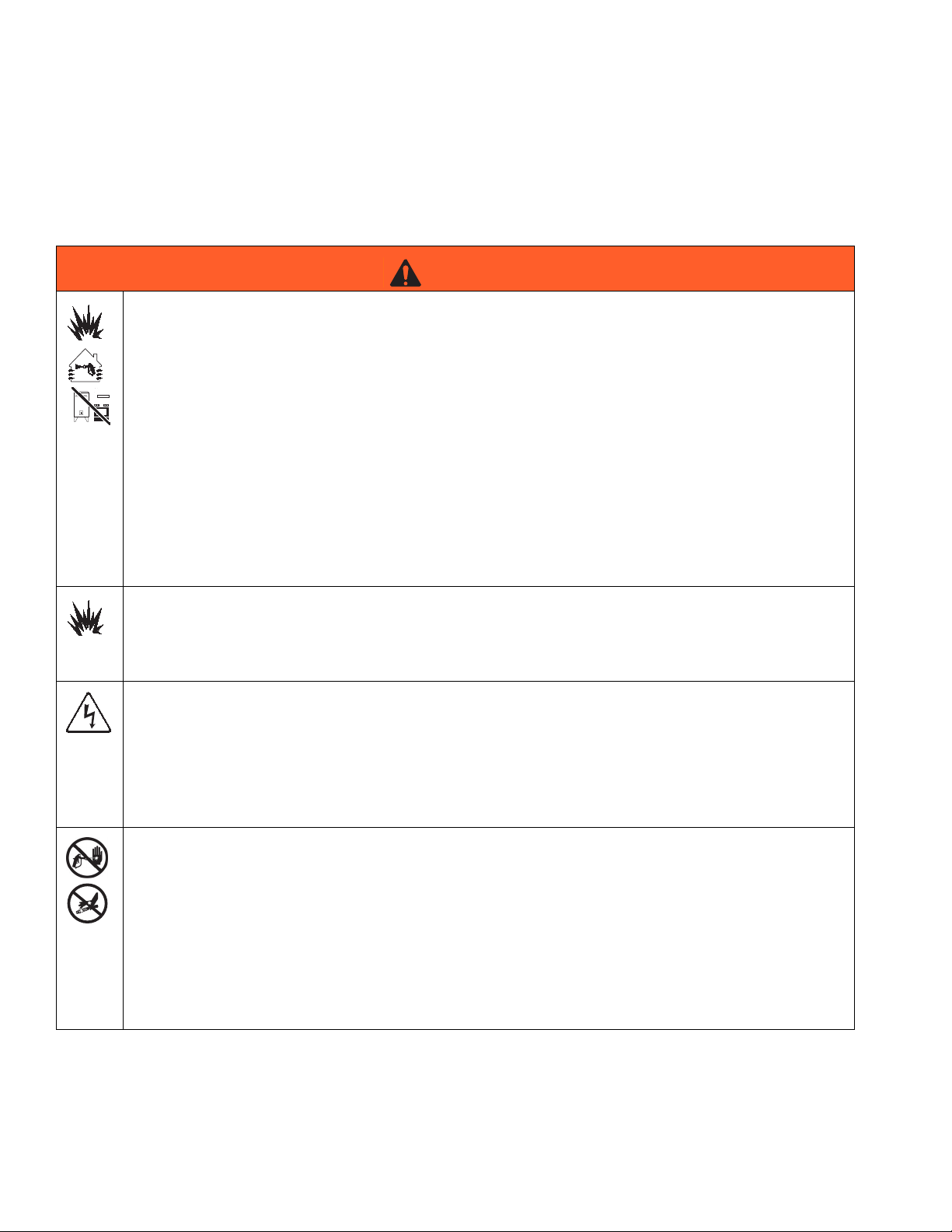
WARNING
FIRE AND EXPLOSION HAZARD
Flammable fumes, such as solvent and paint fumes, in work area can ignite or explode. To help prevent
fire and explosion:
• Use equipment only in well ventilated area.
• Eliminate all ignition sources; such as pilot lights, cigarettes, portable electric lamps, and plastic drop
cloths (potential static arc).
• Keep work area free of debris, including solvent, rags and gasoline.
• Do not plug or unplug power cords, or turn power or light switches on or off when flammable fumes
are present.
• Ground all equipment in the work area.
• Use only grounded hoses.
• Hold gun firmly to side of grounded pail when triggering into pail.
• If there is static sparking or you feel a shock, stop operation immediately. Do not use equipment
until you identify and correct the problem.
• Keep a working fire extinguisher in the work area.
SPECIAL CONDITIONS FOR SAFE USE
• To prevent the risk of electrostatic sparking, the equipment’s non-metallic parts must be cleaned
with only a damp cloth.
• Refer to the Viscon HP Heater manual for special conditions for safe use.
ELECTRIC SHOCK HAZARD
Improper grounding, setup, or usage of the system can cause electric shock.
• Turn off and disconnect power at main switch before disconnecting any cables and before servicing
equipment.
• Connect only to grounded power source.
• All electrical wiring must be done by a qualified electrician and comply with all local codes and
regulations.
SKIN INJECTION HAZARD
High-pressure fluid from gun, hose leaks, or ruptured components will pierce skin. This may look like just
a cut, but it is a serious injury that can result in amputation. Get immediate surgical treatment.
• Do not point gun at anyone or at any part of the body.
• Do not put your hand over the spray tip.
• Do not stop or deflect leaks with your hand, body, glove, or rag.
• Do not spray without tip guard and trigger guard installed.
• Engage trigger lock when not spraying.
•Follow Pressure Relief Procedure in this manual, when you stop spraying and before cleaning,
checking, or servicing equipment.
4 313292G
Page 5
Warnings
WARNING
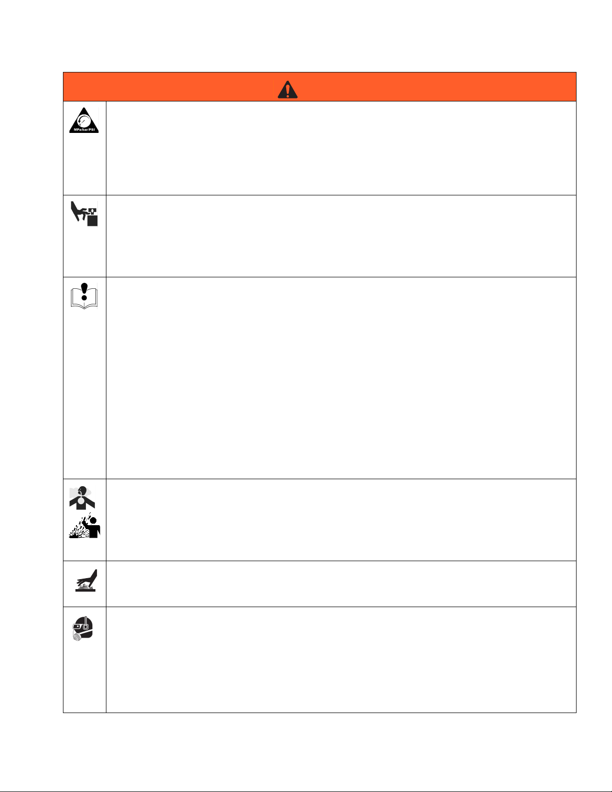
PRESSURIZED EQUIPMENT HAZARD
Fluid from the gun/dispense valve, leaks, or ruptured components can splash in the eyes or on skin and
cause serious injury.
•Follow Pressure Relief Procedure in this manual, when you stop spraying and before cleaning,
checking, or servicing equipment.
• Tighten all fluid connections before operating the equipment.
• Check hoses, tubes, and couplings daily. Replace worn or damaged parts immediately.
MOVING PARTS HAZARD
Moving parts can pinch or amputate fingers and other body parts.
• Keep clear of moving parts.
• Do not operate equipment with protective guards or covers removed.
• Pressurized equipment can start without warning. Before checking, moving, or servicing equipment,
follow the Pressure Relief Procedure in this manual. Disconnect power or air supply.
EQUIPMENT MISUSE HAZARD
Misuse can cause death or serious injury.
• Do not operate the unit when fatigued or under the influence of drugs or alcohol.
• Do not exceed the maximum working pressure or temperature rating of the lowest rated system
component. See Technical Data in all equipment manuals.
• Use fluids and solvents that are compatible with equipment wetted parts. See Technical Data in all
equipment manuals. Read fluid and solvent manufacturer’s warnings. For complete information
about your material, request MSDS forms from distributor or retailer.
• Check equipment daily. Repair or replace worn or damaged parts immediately with genuine manufacturer’s replacement parts only.
• Do not alter or modify equipment.
• Use equipment only for its intended purpose. Call your distributor for information.
• Route hoses and cables away from traffic areas, sharp edges, moving parts, and hot surfaces.
• Do not kink or over bend hoses or use hoses to pull equipment.
• Keep children and animals away from work area.
• Comply with all applicable safety regulations.
TOXIC FLUID OR FUMES HAZARD
Toxic fluids or fumes can cause serious injury or death if splashed in the eyes or on skin, inhaled, or
swallowed.
• Read MSDS’s to know the specific hazards of the fluids you are using.
• Store hazardous fluid in approved containers, and dispose of it according to applicable guidelines.
• Always wear impervious gloves when spraying or cleaning equipment.
BURN HAZARD
Equipment surfaces and fluid that’s heated can become very hot during operation. To avoid severe
burns, do not touch hot fluid or equipment. Wait until equipment/fluid has cooled completely.
PERSONAL PROTECTIVE EQUIPMENT
You must wear appropriate protective equipment when operating, servicing, or when in the operating
area of the equipment to help protect you from serious injury, including eye injury, inhalation of toxic
fumes, burns, and hearing loss. This equipment includes but is not limited to:
• Protective eyewear
• Clothing and respirator as recommended by the fluid and solvent manufacturer
•Gloves
• Hearing protection
313292G 5
Page 6
Models
Models
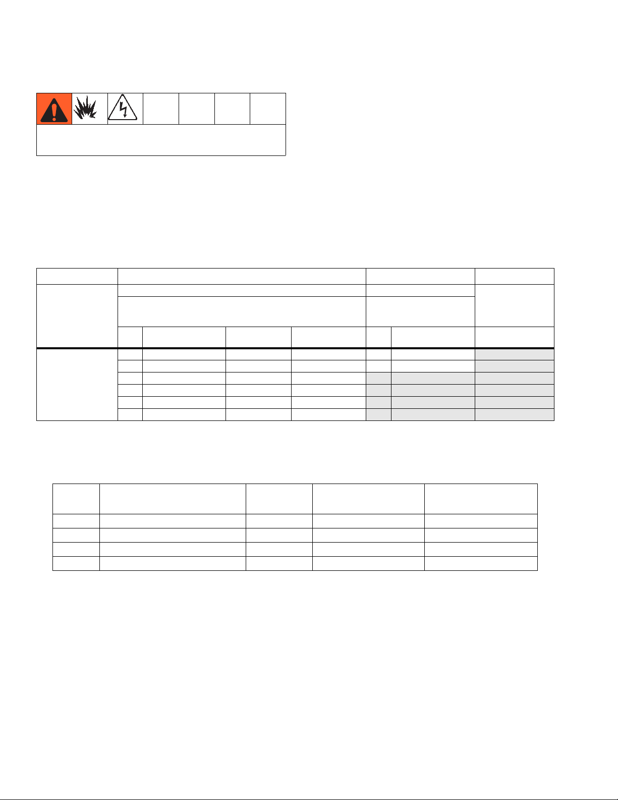
XM OEM sprayers are not approved for use in hazardous locations.
Use the following matrix to define the construction of the sprayer, based on the six digits. For example, Part XMEA00
represents an XM Plural-Component OEM sprayer (XM); 5200 psi pump set with pump filters (E); wall power supply
that is not approved for hazardous areas (A).
NOTE:
To order replacement parts, see Parts section the XM Plural-Component Sprayer Repair-Parts manual 313289. The
digits in the matrix do not correspond to the Ref. Nos. in the Parts drawings and lists.
XM E A
First and Second
Digits
XM
(OEM plural com-
ponent sprayer
without a frame)
(See Table 1 for lower models) Control Box Choice
Pump Set
(hose/gun) Pump Filters
A no pumps A Wall Power Supply
B no pumps
E 5200 psi
F 5200 psi
G 6300 psi
H 6300 psi
Third Digit Fourth Digit
System Choice
Remote
Manifold Control Box Always 00
✔
✔
✔
Table 1: Lower Models and Corresponding Identification Codes
System Pressure
Code
(MPa, bar)
E 5200 psi (35, 350)
Pump
Filters
✔
A Lower
(see manual 311762)
L250C4 L220C4
F 5200 psi (35, 350) L250C3 L220C3
G 6300 psi (49, 490)
✔
L180C4 L145C4
H 6300 psi (49, 490) L180C3 L145C3
00
Fifth and Sixth
Digits
D Alternator
B Lower
(see manual 311762)
NOTE:
See Accessories and Kits, page 25, for a list of available accessories and kits.
6 313292G
Page 7
Overview
Overview
Usage
XM plural-component sprayers can mix and spray most
two-component epoxy and urethane protective coatings.
When using quick-setting materials (less than 10 minute
pot life) a remote mix manifold must be used.
XM plural-component sprayers are operated via user
interface, air controls, and fluid controls.
XM OEM sprayers are not approved for use in hazardous locations.
Isocyanate Hazard
Spraying materials containing isocyanates creates
potentially harmful mists, vapors, and atomized particulates.
Material Self-Ignition
Some materials may become self-igniting if applied
too thick. Read material manufacturer’s warnings and
material MSDS.
Moisture Sensitivity of Isocyanates
Isocyanates (ISO) are catalysts used in two component
urethane coatings. ISO will react with moisture (such as
humidity) to form small, hard, abrasive crystals, which
become suspended in the fluid. Eventually a film will
form on the surface and the ISO will begin to gel,
increasing in viscosity. If used, this partially cured ISO
will reduce performance and the life of all wetted parts.
NOTE:
The amount of film formation and rate of crystallization
varies depending on the blend of ISO, the humidity, and
the temperature.
Read material manufacturer’s warnings and material
MSDS to know specific hazards and precautions
related to isocyanates.
Prevent inhalation of isocyanate mists, vapors, and
atomized particulates by providing sufficient ventilation in the work area. If sufficient ventilation is not
available, a supplied-air respirator is required for
everyone in the work area.
To prevent contact with isocyanates, appropriate personal protective equipment, including chemically
impermeable gloves, boots, aprons, and goggles, is
also required for everyone in the work area.
To prevent exposing ISO to moisture:
• Always use a sealed container with a desiccant
dryer in the vent, or a nitrogen atmosphere. Never
store ISO in an open container.
• Use moisture-proof hoses specifically designed for
ISO, such as those supplied with your system.
• Never use reclaimed solvents, which may contain
moisture. Always keep solvent containers closed
when not in use.
• Never use solvent on one side if it has been contaminated from the other side.
• Always park pumps when you shutdown.
• Always lubricate threaded parts with Part 217374
ISO pump oil or grease when reassembling.
313292G 7
Page 8
Location
Components A and B
IMPORTANT!
Material suppliers can vary in how they refer to plural
component materials.
Be aware that in this manual:
Component A
Component B
NOTE:
This equipment doses the B component into the A component flow. An integration hose must always be used
after the mix manifold and before the static mixer.
NOTE:
Please follow these recommendations for setup:
• use at least a 3/8 in. (10 mm) x 25 ft. (7 m) hose as
the integration hose.
• install a 24-element static mix tube after the integration hose.
refers to resin or major volume.
refers to the hardener or minor volume.
Location
XM OEM sprayers are not approved for use in hazardous locations.
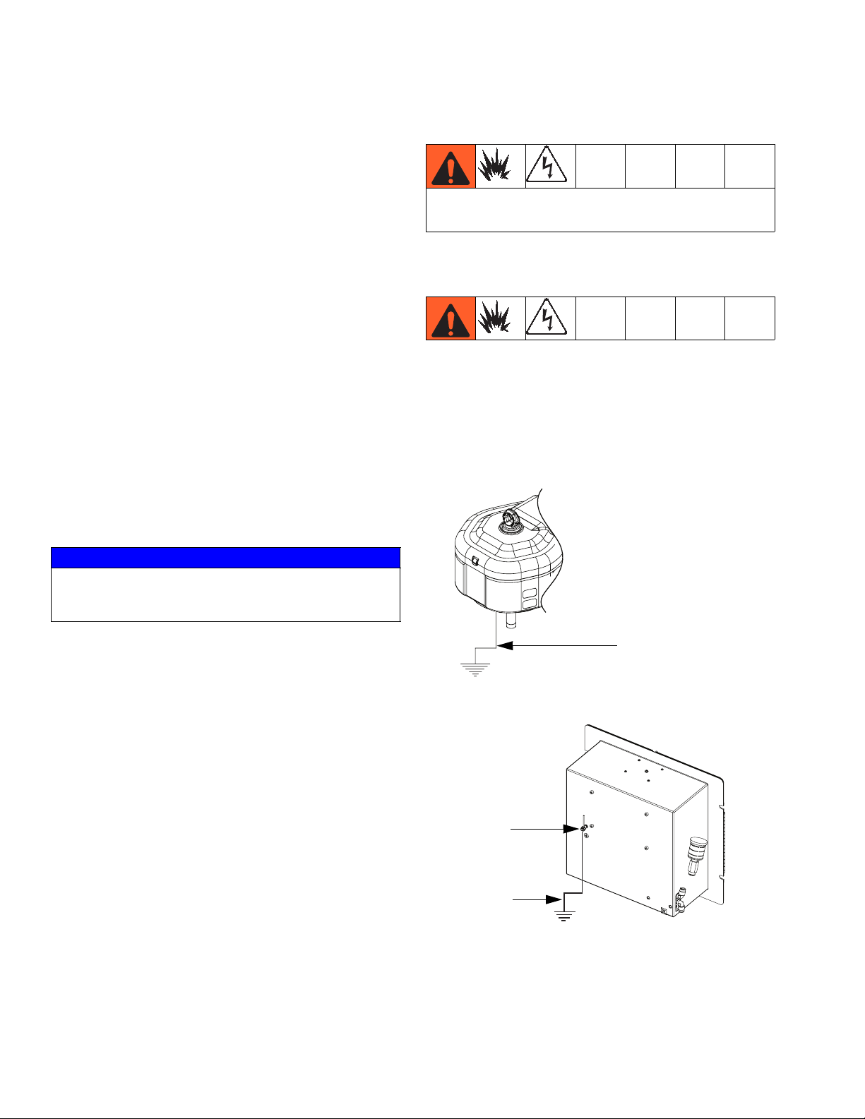
Grounding
Ground control box (ground wire attached) and both air
motors to a true earth ground.
NOTE:
If wall power is used, ground electrical connection properly according to local codes.
Keep Components A and B Separate
NOTICE
To prevent cross-contamination of the equipment’s wetted parts, never interchange component A (resin) and
component B (hardener) parts.
Changing Materials
• When changing materials, flush the equipment multiple times to ensure it is thoroughly clean.
• Always clean the fluid inlet strainers and outlet filter
after flushing, Flush Mixed Material, page 16.
• Check with your material manufacturer for chemical
compatibility.
• Epoxies often have amines on the B (hardener)
side. Polyureas often have amines on the A (resin)
side.
NOTE:
If the amine will switch between the two sides, see
Flush Mixed Material, page 16.
Air Motor
Ground Wire
Control Box
Ground Nut
Control Box
Ground Wire
8 313292G
Page 9
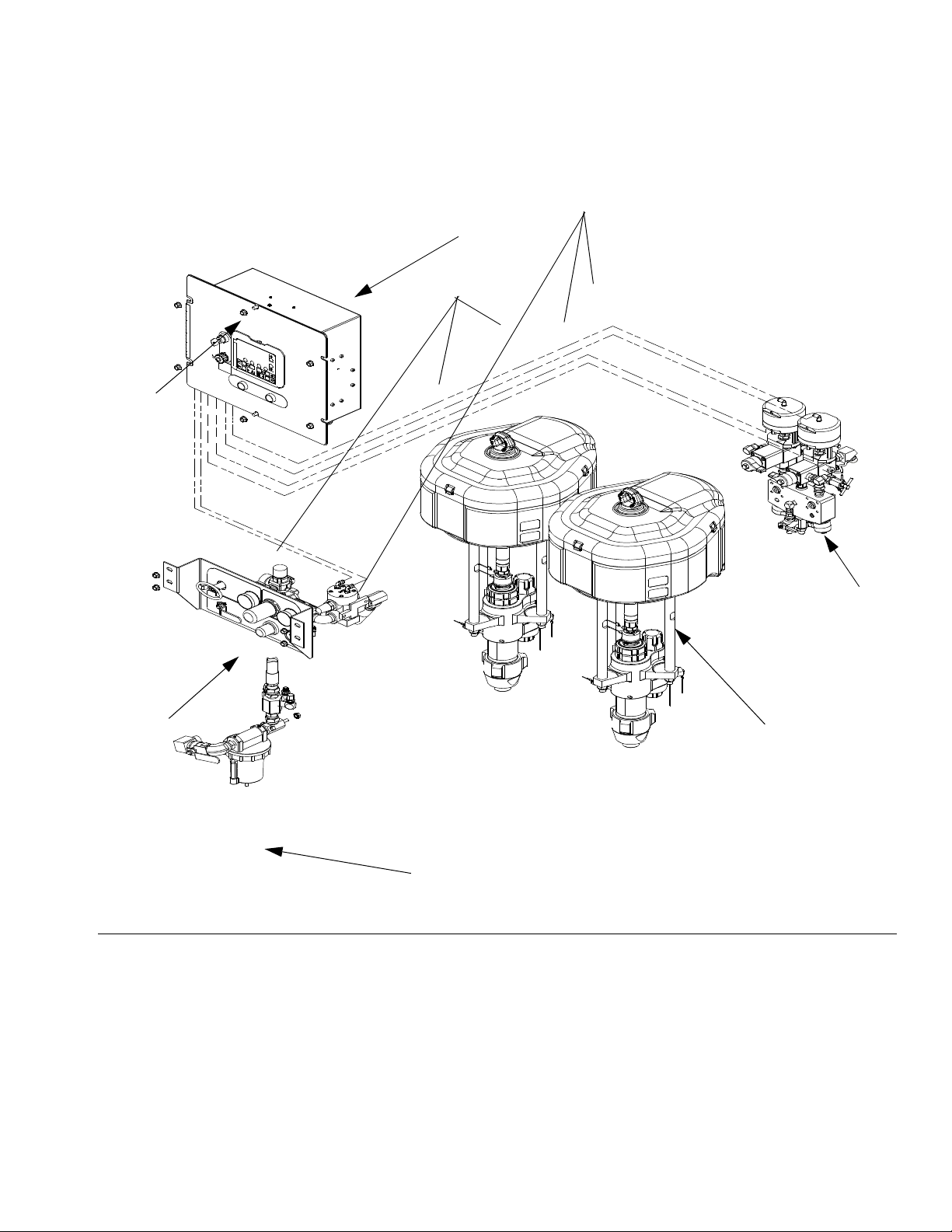
Component Identification
68
D
Component Identification
69
C
E
F
FIG. 1: Typical OEM Sprayer Components
Key:
A Pump Assembly
B Fluid Control Assembly (see Fluid Control Assembly,
page 10)
C Control Box
D User Interface Display (see User Interface Display, page
13)
B
A
E Air Controls (see Air Controls, page 11)
F Air Inlet Manifold Assembly
68 Air Line
69 Air Line
313292G 9
Page 10
Component Identification
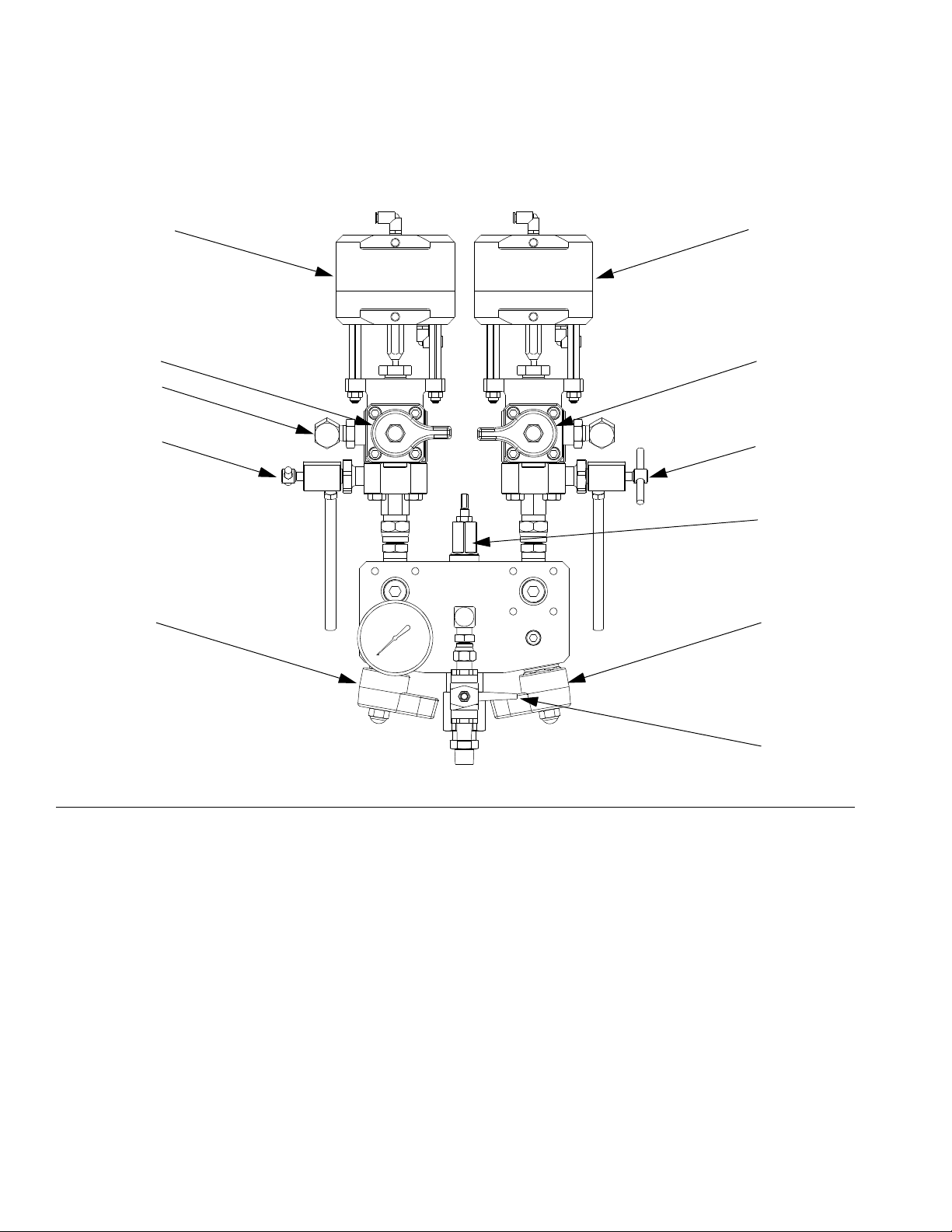
Fluid Control Assembly
AC
AL
AE
AH
AA
AB
AD
AF
AG
AJ
AK
r_XM1A00_312359_313289_18A
FIG. 2: Fluid Control Assembly
AA Dosing Valve A
AB Dosing Valve B
AC Recirculation Valve A
AD Recirculation Valve B
AE Sampling Valve A
10 313292G
AF Sampling Valve B
AG Restriction Valve
AH Mix Manifold Shutoff / Check Valve A
AJ Mix Manifold Shutoff / Check Valve B
AK Solvent Shutoff Valve
AL Pressure Sensor (hidden)
Page 11

Air Controls
CA
CB
FIG. 3: Air Controls
Component Identification
CC
CD
CE
CF
CG
r_XM1A00_312359_313289_14A
CA Main Pump and Air On/Off Control
CB Solvent Pump Air On/Off Control
CC Inlet Air Pressure Gauge
CD Main Pump Air Regulator
CE Main Pump Air Regulator Gauge
CF Solvent Pump Air Gauge
CG Solvent Pump Air Regulator
313292G 11
Page 12

Component Identification
User Interface
DG
DF
DA
DD
DM
DB
DJ
IG
. 4: User Interface
F
DR
Buttons LEDs
DK
DC
ti13365a
DN
DH
DE
DP
Call
out Button Function
DA Display
Screen
DB Start Initiates Active Run Mode function cur-
DC Stop Terminates Active Run Mode function
DD Enter Press to open drop-down fields, selection
DE Alarm
Reset
DF Left/Right Move between screens in run or setup
DG Function Activates mode or action represented by
DH Up/Down Move between selection boxes,
DJ Setup Key
Lock
DR USB Port Connection for data download. Use only
Use to view GCA display. Ratio, Mode
Selection, Error Conditions, Totalizers,
System Information.
rently selected in Run Screen.
currently selected.
options, and save values.
Resets alarms and advisories.
modes.
the icon above each of the four buttons in
the LCD.
drop-down fields, and selectable values
within Setup screens.
Change ratio or enter Setup mode.
in non-hazardous areas.
There are four types of LEDs on the display.
Call
out LED Function
DK Blue Dosing valve active
•
on - dosing valve is active
•
off - dosing valve is not active
DM Green Spray mode active
•
selected mode is on (active)
•
selected mode is off (inactive)
DN Red Alarm
•
on - alarm is present
•
off - no alarm
DP Yellow Warning
•
on - is active.
•
off - no warning indicated. Ratio
and setup fields are not changeable.
•
flashing - key is present and
turned. Ratio and setup fields
are changeable.
12 313292G
Page 13

Component Identification
User Interface Display
NOTE:
For details regarding the user interface display see the
XM Plural-Component Sprayer operation manual
312359.
Main Display Screen Components
The following figure calls out the navigational, status, and general informational components of each display screen.
Current Date and Time
Current Status Bar
Navigate to screens
within same group
Navigational Bar
F
IG
. 5: Main Display Screen Components
Remaining Potlife Time
Function Display
Go back one screen
313292G 13
Page 14

Pressure Relief Procedure
Pressure Relief Procedure
Follow Flush Mixed Material procedure prior to
relieving pressure.
Follow Pressure Relief Procedure when you stop
spraying or dispensing; and before cleaning, checking, servicing, or transporting equipment.
Relieve A and B Fluid Pressure
1. Engage trigger lock.
ti1949a
8. Engage trigger lock.
ti1949a
Relieve Pump Fluid Pressure and Flush Mix
Hose
9. Close mix manifold valves (AH, AJ), then open solvent flush valve (AK) on mix manifold.
AK
AH
AJ
2. Press Stop .
3. If fluid heaters are used, shut them off.
.
4. Shut off feed pumps, if used.
5. Remove spray tip and clean.
6. Disengage trigger lock.
ti1950a
7. Hold a metal part of the gun firmly to a grounded
metal pail with a splash guard in place. Trigger gun
to relieve pressure in material hoses.
10. Open solvent flush ball valve (CB). Use lowest pressure needed to flush material out of hose.
CB
11. Disengage trigger lock.
ti1950a
ti1953a
14 313292G
Page 15

12. Hold a metal part of the gun firmly to a grounded
metal pail with a splash guard in place. Trigger gun
to flush mixed material out of line with clean solvent.
13. Shut off solvent pump air control valve (CB).
14. Repeat steps 11 and 12. Then continue to step 15.
15. Close solvent flush valve (AK) on mix manifold.
AK
Pressure Relief Procedure
16. Release any residual gun pressure and engage trigger lock.
ti1949a
313292G 15
Page 16

Flush Mixed Material
Flush Mixed Material
Flush Mix Manifold
Use Solvent Pump
3. Open solvent shutoff valve (AK) at mix manifold.
4. Open solvent pump air valve (CB). Pull out and
slowly turn solvent pump air regulator (CG) clockwise to increase air pressure. Use lowest possible
pressure.
.
1. Press Stop to turn off system. Engage trigger
lock. Remove spray tip.
ti1949a
ti1948a
2. Ensure sampling valves (AE, AF) and mix manifold
valves (AH, AJ) are closed.
AE
AF
AK
CB
5. Disengage trigger lock and trigger gun into a
grounded pail. Use a pail lid with a hole to dispense
through. Seal around hole and gun with a rag to prevent splash back. Be careful to keep fingers away
from front of gun. Flush out mixed material until
clean solvent dispenses.
ti1950a
CG
ti1953a
AH
16 313292G
AJ
Page 17

6. Close solvent pump air valve (CB) and solvent shutoff valve (AK) at mix manifold. Trigger spray gun to
relieve pressure.
AK
7. Engage trigger lock.
Flush Mixed Material
ti1949a
8. Disassemble and clean spray tip with solvent by
hand. Reinstall on gun.
313292G 17
Page 18

Installation and Setup
Installation and Setup
NOTE:
See , page 27, to aid in component installation.
Connect Air Lines
Refer to component identification in FIG. 1, page 9.
Refer to the pneumatic schematic drawings in the XM
Plural-Component Sprayer repair-parts manual 313289
for guidance.
• Connect air lines (68, 69) between the fluid control
assembly (B) and the control box (C).
• Connect air lines (68, 69) between the air controls
assembly (E) and the control box.
Connect Fluid Hoses
Use the following illustration as a guide to connect the
fluid hoses.
• Connect air hose (12) between air controls assembly and both air motors. (Hose called out has 12(A)
and 12 (B)).
12(B)
12(A)
12(C)
12 (A and B)
Connect Sensor Cables
Recirculation
Hose (gray)
Hose to Pump
Lower (black)
Recirculation
Hose (gray)
Connect Air Hoses
• Connect air hose (12) between air inlet manifold and
air controls assembly. (Hose called out as 12(C)).
Connect pressure and temperature sensor cables (supplied with fluid control assembly (B)) to the fluid control
module.
Fluid
Control
Module
B
r_xmaa00_313292_4a
18 313292G
Page 19

Operation
For operation instructions, see XM Plural-Component
Sprayer Operation manual 312359.
Repair
For maintenance, troubleshooting, and repair instructions, see XM Plural-Component Sprayer Repair-Parts
manual 313289.
Schematics
See XM Plural-Component Sprayer Repair-Parts manual 313289 for all electrical schematics.
Operation
313292G 19
Page 20

Parts
Parts
65
3
4
7
38
2
1
(FRONT VIEW)
5
38
12
73
15
(REAR VIEW)
66
67
(REAR VIEW)
14
12
32
30
31
17
11
12
10
(FRONT VIEW)
36
37
34
35
33
12
12
6
38
9
8
20 313292G
Page 21

43
Parts
50
XM_D00 Systems Only
51
19
22
52
23
20
49
44
46
48
47
45
XM_A00 Systems Only
22
20
24
25
26
313292G 21
28
29
27
Page 22

Parts
XMA_00 and XMB_00 Parts
NOTE: Reference numbers not listed are not
included with XMA_00 and XMB_00 systems.
Ref. Part Description Qty.
2 255684 MANIFOLD, mix; see manual
313289
3 VALVE, ratio control, left; see man-
ual 313289
4 VALVE, ratio control, right; see
manual 313289
5 255761 MODULE, air controls, upper; see
manual 313289
6 255762 MANIFOLD, inlet air distribution;
see manual 313289
7 255771 BOX; see manual 313289 1
19✓ 255728 MODULE, alternator 1
20 110637 SCREW, mach, pan hd
XMAA00 and XMBA00 3
XMAD00 and XMBD00 5
21✓★ C12508 TUBING, nylon, round 5
22 15V778 CABLE, I.S.CAN, female/female;
20 in.
23✓ 15V782 CABLE, I.S. CAN, male/female;
20 in.
24✓ 15V783 CABLE, male/female; 39 in. 1
25❄ 15V747 POWER SUPPLY, assy.; 24Vdc,
2.5A, 60W
26❄ 100035 SCREW, machine, pan hd 4
27❄ 15X407 CABLE, power 1
28❄ 115306 FILTER, power 1
29❄ 15V779 CABLE, I.S. CAN, female/female;
34 in.
38 112958 NUT, hex, flanged 11
40★▲ 15X393 LABEL, warning, USB 1
41★ 15X126 LABEL, codes 1
42★▲ 15W598 LABEL, warning 1
43✓ 156971 NIPPLE, short 1
44✓ 115243 REGULATOR, air, 1/4 npt 1
45✓ 112307 ELBOW, street; 1/8 nptf x 1/8 nptm 1
46✓ 15W017 VALVE, safety, regulator 1
47✓ 115841 ELBOW, swivel, male; 1/4 npt 1
48✓ 104655 GAUGE, pressure, air 1
49✓ 156823 UNION, swivel 1
50✓ 102063 WASHER, lock, ext 1
51✓ 15B090 WIRE, grounding, door 1
52✓ 100284 NUT, hex mscr 1
53✖ 121295 SCREW, cap, socket hd 8
54✖★ 158491 NIPPLE; 1/2 npt 4
55✖ 100361 PLUG, pipe; 1/2 in. - 14 nptf 2
56✖ 15R529 BLOCK, manifold 2
57✖ 156684 ADAPTER, union 2
58✖ 121139 O-RING 2
59✖ 15J594 HOUSING, valve 2
60✖ 255747 CARTRIDGE, valve 2
61✖ 15R380 HANDLE, green 1
62✖ 15J916 HANDLE, blue 1
Ref. Part Description Qty.
63✖ 117623 NUT, cap; 3/8-16 unc 2
64✖ 262522 CARRIAGE 1
65 111801 SCREW, cap, hex hd 12
66 108636 MUFFLER 1
67 121688 CONNECTOR, 3/8 npt x 3/8 tube 1
68 054175 TUBE, nylon, 1/4 OD, black; 10 ft;
1
1
69 054757 TUBE, nylon, 1/4 OD natural; 10 ft;
1
73 238909 WIRE, grounding assy 1
1
74★ 16A004 FLASH DRIVE, USB, 2.0 1
76✖ 162505 UNION, swivel; 3/8 male x 1/2
1
77✖ 222200 VALVE, restrictor 1
78✖ 155699 ELBOW, street 1
79✖ 159239 NIPPLE, pipe; 1/2 x 3/8 npt 1
80✖★ 156849 PIPE, nipple 1
81✖★ 164672 ADAPTER 1
82★ 126786 WRENCH, restrictor 1
92✖ 16N367 COUPLING, 1/2 x 3.5 in. 1
1
✓
1
1
Included with XMAD00 and XMBD00 systems only.
❄
Included with XMAA00 and XMBA00 systems only.
✖
Included with XMBA00 and XMBD00 systems only.
★
Not shown.
▲
Replacement Danger and Warning labels, tags, and
see Component Identification,
page 9
see Component Identification,
page 9
female npt
cards are available at no cost.
1
XMBA00 and XMBD00 Systems Only
2
64
57
58
65
62
53
60
55
63
61
92
77
54
54
76
1
65
56
59
78
79
WLD
22 313292G
Page 23

Parts
XME_00 and XMF_00 Parts
NOTE: Reference numbers not listed are not
included with XME_00 and XMF_00 systems.
Qty
Ref. Part Description
1 257055 MOTOR, 6500, de-icing; see man-
ual 311238
2 255684 MANIFOLD, mix; see manual
313289
3 VALVE, ratio control, left; see man-
ual 313289
4 VALVE, ratio control, right; see
manual 313289
5 255761 MODULE, air controls, upper; see
manual 313289
6 255762 MANIFOLD, inlet air distribution;
see manual 313289
7 255771 BOX, control; see manual 313289 1
8 L250C4 LOWER, Xtreme, 250; see manual
311762
9 L220C4 LOWER, Xtreme, 220; see manual
311762
10 15H652 LABEL, Xtreme, X50 1
11 15H654 LABEL, Xtreme, X60 1
12 15B554 HOSE, coupled; 48 in. 3
14 NXT102 CONTROL, de-ice, assy 2
15 119402 CABLE, coiled 2
16★ 15T258 WRENCH 1
17 15M987 ELBOW, 60 degrees 2
19✠ 255728 MODULE, alternator 1
20 110637 SCREW, machine, pan hd
XMEA00 and XMFA00 3
XMED00 and XMFD00 5
21✠★ C12508 TUBING, nylon, round 5
22 15V778 CABLE,I.S.CAN, female/female;
20 in.
23✠ 15V782 CABLE,I.S. CAN, male/female;
20 in.
24✠ 15V783 CABLE, male/female; 39 in. 1
25✿ 15V747 POWER SUPPLY, assy.; 24Vdc,
2.5A, 60W
26✿ 100035 SCREW, machine, pan hd 4
27✿ 15X407 CABLE, power 1
28✿ 115306 FILTER, power 1
29✿ 15V779 CABLE, I.S. CAN, female/female;
34 in.
30 257150 ROD, tie 6
31 101712 NUT, lock; 5/8 in. - 11 unc 6
32 15H392 ROD, adapter 2
33 244819 COUPLING, assy 2
34 244820 CLIP, hairpin with lanyard 2
35 197340 COVER, coupler 2
36 100133 WASHER, LOCK; 3/8 8
37 100101 SCREW, cap, hex hd 8
38 112958 NUT, hex, flanged 11
39 160327 UNION, adapter; 90 degrees 2
Ref. Part Description
40★▲ 15X393 LABEL, warning, USB 1
41★ 15X126 LABEL, codes 1
42★▲ 15W598 LABEL, warning 1
43✠ 156971 NIPPLE, short 1
44✠ 115243 REGULATOR, air; 1/4 npt 1
.
45✠ 112307 ELBOW, street; 1/8 nptf x 1/8 nptm 1
2
46✠ 15W017 VALVE, safety, regulator 1
47✠ 115841 ELBOW, swivel, male; 1/4 npt 1
1
48✠ 104655 GAUGE, pressure, air 1
49✠ 156823 UNION, swivel 1
1
50✠ 102063 WASHER, lock, ext 1
51✠ 15B090 WIRE, grounding, door 1
1
52✠ 100284 NUT, hex mscr 1
65 111801 SCREW, cap, hex hd 12
1
66 108636 MUFFLER 1
67 121688 CONNECTOR; 3/8 npt x 3/8 tube 1
1
68 054172 TUBE, nylon, 1/4 OD, black; 10 ft;
see Component Identification,
1
69 054757 TUBE, nylon, 1/4 OD natural; 10 ft;
1
73 238909 WIRE, grounding assy 1
74★ 16A004 FLASH DRIVE, USB, 2.0 1
82★ 126786 WRENCH, restrictor 1
Included with XMED00 and XMFD00 systems only.
✠
✿
Included with XMEA00 and XMFA00 systems only.
★
Not shown.
▲
Replacement Danger and Warning labels, tags, and
page 9
see Component Identification,
page 9
cards are available at no cost.
1
1
1
1
Qty
.
313292G 23
Page 24

Parts
XMG_00 and XMH_00 Parts
NOTE: Reference numbers not listed are not
included with XMG_00 and XMH_00 systems.
Qty
Ref. Part Description
1 257055 MOTOR, 6500, de-icing; see man-
ual 311238
2 255684 MANIFOLD, mix; see manual
313289
3 VALVE, ratio control, left; see man-
ual 313289
4 VALVE, ratio control, right; see
manual 313289
5 255761 MODULE, air controls, upper; see
manual 313289
6 255762 MANIFOLD, inlet air distribution;
see manual 313289
7 255771 BOX, control; see manual 313289 1
8 L180C4 LOWER, Xtreme, 180; see manual
311762
9 L145C4 LOWER, Xtreme, 145; see manual
311762
10 LABEL, Xtreme, X70 1
11 LABEL, Xtreme, X90 1
12 15B554 HOSE, coupled; 48 in. 3
14 NXT102 CONTROL, de-ice, assy 2
15 119402 CABLE, coiled 2
16★ 15T258 WRENCH 1
17 15M987 ELBOW, 60 degrees 2
19‡ 255728 MODULE, alternator 1
20 110637 SCREW, mach, pan hd
XMGA00 and XMHA00 3
XMGD00 and XMHD00 5
21‡★ C12508 TUBING, nylon, round 5
22 15V778 CABLE,I.S.CAN, female/female;
20 in.
23‡ 15V782 CABLE,I.S. CAN, male/female;
20 in.
24‡ 15V783 CABLE, male/female; 39 in. 1
25◆ 15V747 POWER SUPPLY, assy.; 24Vdc,
2.5A, 60W
26◆ 100035 SCREW, machine, pan hd 4
27◆ 15X407 CABLE, power 1
28◆ 115306 FILTER, power 1
29◆ 15V779 CABLE, I.S. CAN, female/female;
34 in.
30 257150 ROD, tie 6
31 101712 NUT, lock; 5/8 in. - 11 unc 6
32 15H392 ROD, adapter 2
33 244819 COUPLING, assy 2
34 244820 CLIP, hairpin with lanyard 2
35 197340 COVER, coupler 2
36 100133 WASHER, LOCK; 3/8 8
37 100101 SCREW, cap, hex hd 8
38 112958 NUT, hex, flanged 11
39 160327 UNION, adapter; 90 degrees 2
Ref. Part Description
40★▲ 15X393 LABEL, warning, USB 1
41★ 15X126 LABEL, codes 1
42★▲ 15W598 LABEL, warning 1
43‡ 156971 NIPPLE, short 1
44‡ 115243 REGULATOR, air; 1/4 npt 1
.
45‡ 112307 ELBOW, street; 1/8 nptf x 1/8 nptm 1
2
46‡ 15W017 VALVE, safety, regulator 1
47‡ 115841 ELBOW, swivel, male; 1/4 npt 1
1
48‡ 104655 GAUGE, pressure, air 1
49‡ 156823 UNION, swivel 1
1
50‡ 102063 WASHER, lock, ext 1
51‡ 15B090 WIRE, grounding, door 1
1
52‡ 100284 NUT, hex mscr 1
65 111801 SCREW, cap, hex hd 12
1
66 108636 MUFFLER 1
67 121688 CONNECTOR; 3/8 npt x 3/8 tube 1
1
68 054172 TUBE, nylon, 1/4 OD, black; 10 ft;
see Component Identification,
1
69 054757 TUBE, nylon, 1/4 OD natural; 10 ft;
1
73 238909 WIRE, grounding assy 1
74★ 16A004 FLASH DRIVE, USB, 2.0 1
82★ 126786 WRENCH, restrictor 1
Included with XMGD00 and XMHD00 systems only.
‡
◆
Included with XMGA00 and XMHA00 systems only.
★
Not shown.
▲
Replacement Danger and Warning labels, tags, and
page 9
see
Component Identification,
page 9
cards are available at no cost.
1
1
1
1
Qty
.
24 313292G
Page 25

Accessories and Kits
Not all accessories and kits are approved for use in
hazardous locations. Refer to the specific accessory
and kit manuals for approval details.
Accessories and Kits
20-Gallon Hopper Kit, 255963
One complete double-wall 20-gallon hopper. See manual 312747 for more information.
Hopper Heater Kit (240V), 256257
For heating fluid in a 20-gallon hopper. See manual
312747 for more information.
T2 Feed Pump Kit, 256275
For supplying viscous material from a 20-gallon hopper
to an XM sprayer. See manual 312769 for more information.
5:1 Feed Pump Kit, 256255
For supplying viscous materials from a 20-gallon hopper
to an XM sprayer. See manual 312769 for more information.
5:1 Drum Feed Kit, 256276
One 5:1 pump feed kit and one Twistork agitator kit for
mixing and supplying viscous materials from a with
55-gallon drum to an XM sprayer. See manual 312769
for more information.
Hopper/Hose Heat Circulation Kit, 256273
For circulating heated water through 20-gallon hoppers,
heated hose, and Viscon HP heater. See manual
313259 for more information.
Desiccant Dryer Kit, 256512
For use with 20-gallon hoppers. See manual 406739 for
more information.
Lower Strainer and Valve Kit, 256653
For straining material from a feed pump to an XM
sprayer fluid inlet. See manual 312770 for more information.
7-Gallon Hopper and Bracket Kit, 256260
One 7-gallon hopper and mounting brackets. Mounts to
the side or back of an XM sprayer. See manual 406999
for more information.
Electric Heated Hose Power Supply Kit,
256876
For monitoring and controlling fluid temperature in
low-voltage heated hoses. See manual 313258 for more
information.
2:1 Drum Feed Kit, 256232
One T2 pump feed kit and one Twistork agitator kit for
mixing and supplying viscous materials from a with
55-gallon drum to an XM sprayer. See manual 312769
for more information.
313292G 25
Page 26

Accessories and Kits
5000 psi Two-Component Main Heated
Hose Set Kit
Electric heated hose set for adding additional sections.
Part Description
248907 Heated hose set; 1/4 in. ID x 3/8 in. ID;
50 ft.
248908 Heated hose set; 3/8 in. ID x 3/8 in. ID;
50 ft.
10:1 Drum Feed Kit, 256433
For supplying highly viscous material from a 55-gallon
drum to an XM sprayer. See manual 312769 for more
information.
Shutoff/Check Valve Kit, 255278
For replacing shutoff valve or check valve. See manual
313343 for more information.
Alternator Conversion Kit, 256991
For converting an XM sprayer from wall power supply to
intrinsically safe alternator power supply. See manual
313293 for more information.
Mix Manifold Kit, 255684
See manual 312749 for more information.
Remote Mix Manifold and Carriage Kit,
256980
For converting to a remote mix manifold kit with a protective guard. See manual 312749 for more information.
26 313292G
Page 27

Accessories and Kits
313292G 27
Page 28

Dimensions
Dimensions
Fluid Control Assembly
Mounting Plate
MANIFOLD MOUNTING PLANE
1.440 in.
(36.58 mm)
0.205 in.
(5.21 mm)
DOSING MOUNTING PLANE
1.440 in.
(36.58 mm)
4.940 in.
(125.48 mm)
1.440 in.
(36.58 mm)
3.970 in.
(100.84 mm)
8 X FULL R .380
2.180 in.
(55.37 mm)
r_xma000_313292_11a
28 313292G
Page 29

Fluid Control Assembly
1.440 in.
(36.58 mm)
4 X 5/16-18 UNC 2B
Dimensions
Dosing Valve Assembly
r_xma000_313292_10a
1.440 in.
(36.58 mm)
1.440 in.
(36.58 mm)
1.440 in.
(36.58 mm)
8 X 5/16-18 UNC 2B
Mix Manifold Assembly
6.380 in.
(162.05 mm)
1.440 in.
(36.58 mm)
4.940 in.
(125.48 mm)
r_xma000_313292_9a
313292G 29
Page 30

Dimensions
15.250 in.
(387.35 mm)
6.940 in.
(176.28 mm)
Control Box Assembly
19.000 in.
(482.60 mm)
r_xma000_313292_7a
10.000 in.
(254.00 mm)
Air Control Assembly
4 X FULL R .500
(79.50 mm)
8 X FULL R .440
2.000 in.
(50.80 mm)
15.000 in.
(381.00 mm)
3.130 in.
0.750 in.
(19.05 mm)
15.920 in.
(404.37 mm)
17.970 in.
r_xma000_313292_8a
30 313292G
(456.44 mm)
Page 31

Technical Data
Technical Data
Mixed ratio range . . . . . . . . . . . . . . . . . . . . . . . . . . . . . . . 1:1-10:1 (in 0.1 increments)
Ratio tolerance range . . . . . . . . . . . . . . . . . . . . . . . . . . . . +/- 5%
Flow rates
Minimum . . . . . . . . . . . . . . . . . . . . . . . . . . . . . . . . . .
Maximum . . . . . . . . . . . . . . . . . . . . . . . . . . . . . . . . . .
Fluid viscosity range . . . . . . . . . . . . . . . . . . . . . . . . . . . . . 200-20,000 cps (heavier viscosities can be mixed using
Fluid filtration . . . . . . . . . . . . . . . . . . . . . . . . . . . . . . . . . . 60 mesh, (238 micron) standard on pump outlets (filter
Air inlet . . . . . . . . . . . . . . . . . . . . . . . . . . . . . . . . . . . . . . . 3/4 npt(f)
Fluid inlets without feed kits . . . . . . . . . . . . . . . . . . . . . . . 1 1/4 npt(m)
Maximum fluid working pressure of mixed material
50:1 . . . . . . . . . . . . . . . . . . . . . . . . . . . . . . . . . . . . . .
70:1 . . . . . . . . . . . . . . . . . . . . . . . . . . . . . . . . . . . . . .
Maximum fluid temperature . . . . . . . . . . . . . . . . . . . . . . . 160° F (71° C)
Air supply pressure range . . . . . . . . . . . . . . . . . . . . . . . . 50-150 psi (0.35-1.0 MPa, 3.5-10.3 bar)
Maximum pump air set pressure
50:1 . . . . . . . . . . . . . . . . . . . . . . . . . . . . . . . . . . . . . .
70:1 . . . . . . . . . . . . . . . . . . . . . . . . . . . . . . . . . . . . . .
Maximum pump inlet fluid feed pressure . . . . . . . . . . . . . 250 psi (1.7 MPa, 17 bar)
Maximum air consumption at 100 psi (0.7 MPa, 7.0 bar)
in scfm (m
Ambient temperature range
Environmental conditions rating . . . . . . . . . . . . . . . . . . . . Indoor/outdoor use
Sound pressure . . . . . . . . . . . . . . . . . . . . . . . . . . . . . . . . 86 dBA at 100 psi (0.7 MPa, 7 bar)
Sound power . . . . . . . . . . . . . . . . . . . . . . . . . . . . . . . . . . 98 dBA at 100 psi (0.7 MPa, 7 bar)
Wetted parts
3
/min.) . . . . . . . . . . . . . . . . . . . . . . . . . . . . . . . 70 scfm per gpm (1.96 m3/min. per lpm)
Operating . . . . . . . . . . . . . . . . . . . . . . . . . . . . . . . . . .
Storage . . . . . . . . . . . . . . . . . . . . . . . . . . . . . . . . . . .
Suction tubes . . . . . . . . . . . . . . . . . . . . . . . . . . . . . . .
Flush pump . . . . . . . . . . . . . . . . . . . . . . . . . . . . . . . .
Hoses. . . . . . . . . . . . . . . . . . . . . . . . . . . . . . . . . . . . .
Pumps (A and B) . . . . . . . . . . . . . . . . . . . . . . . . . . . .
Metering valves . . . . . . . . . . . . . . . . . . . . . . . . . . . . .
Manifold . . . . . . . . . . . . . . . . . . . . . . . . . . . . . . . . . . .
Mixer . . . . . . . . . . . . . . . . . . . . . . . . . . . . . . . . . . . . .
Spray gun. . . . . . . . . . . . . . . . . . . . . . . . . . . . . . . . . .
1 qt./min. (0.95 liter/min.)*
3 gal./min/ (11.4 liter/min.)
heat, circulation, and/or pressure feeding)
assembly not included on some models)
5200 psi (35.8 MPa, 358 bar)
6300 psi (43.5 MPa, 435 bar)
100 psi (0.7 MPa, 7.0 bar)
90 psi (0.62 MPa, 6.2 bar)
32-135° F (0-57° C)
30-160° F (-1-71° C)
Altitude up to 4000 m
Maximum relative humidity to 99% up to 130° F (54° C)
Pollution degree (11)
Installation category (2)
aluminum
carbide, PTFE, stainless steel, UHMWPE
nylon
carbon steel, alloy steel, 303, 440, 17-ph grades stainless
steel, zinc and nickel plating, ductile iron, tungsten carbide, PTFE, leather
carbon steel, nickel plating, carbide, polyethylene, leather
carbon steel, nickel plating, carbide, 302 stainless steel,
PTFE, UHMWPE
stainless steel housing with acetal elements
Refer to spray gun manual
* Minimum flow rate is dependent on material being sprayed and mixing capability. Test your material specific to
flow rate.
313292G 31
Page 32

Graco Standard Warranty
Graco warrants all equipment referenced in this document which is manufactured by Graco and bearing its name to be free from defects in
material and workmanship on the date of sale to the original purchaser for use. With the exception of any special, extended, or limited warranty
published by Graco, Graco will, for a period of twelve months from the date of sale, repair or replace any part of the equipment determined by
Graco to be defective. This warranty applies only when the equipment is installed, operated and maintained in accordance with Graco’s written
recommendations.
This warranty does not cover, and Graco shall not be liable for general wear and tear, or any malfunction, damage or wear caused by faulty
installation, misapplication, abrasion, corrosion, inadequate or improper maintenance, negligence, accident, tampering, or substitution of
non-Graco component parts. Nor shall Graco be liable for malfunction, damage or wear caused by the incompatibility of Graco equipment with
structures, accessories, equipment or materials not supplied by Graco, or the improper design, manufacture, installation, operation or
maintenance of structures, accessories, equipment or materials not supplied by Graco.
This warranty is conditioned upon the prepaid return of the equipment claimed to be defective to an authorized Graco distributor for verification of
the claimed defect. If the claimed defect is verified, Graco will repair or replace free of charge any defective parts. The equipment will be returned
to the original purchaser transportation prepaid. If inspection of the equipment does not disclose any defect in material or workmanship, repairs
will be made at a reasonable charge, which charges may include the costs of parts, labor, and transportation.
THIS WARRANTY IS EXCLUSIVE, AND IS IN LIEU OF ANY OTHER WARRANTIES, EXPRESS OR IMPLIED, INCLUDING BUT NOT
LIMITED TO WARRANTY OF MERCHANTABILITY OR WARRANTY OF FITNESS FOR A PARTICULAR PURPOSE.
Graco’s sole obligation and buyer’s sole remedy for any breach of warranty shall be as set forth above. The buyer agrees that no other remedy
(including, but not limited to, incidental or consequential damages for lost profits, lost sales, injury to person or property, or any other incidental or
consequential loss) shall be available. Any action for breach of warranty must be brought within two (2) years of the date of sale.
GRACO MAKES NO WARRANTY, AND DISCLAIMS ALL IMPLIED WARRANTIES OF MERCHANTABILITY AND FITNESS FOR A
PARTICULAR PURPOSE, IN CONNECTION WITH ACCESSORIES, EQUIPMENT, MATERIALS OR COMPONENTS SOLD BUT NOT
MANUFACTURED BY GRACO. These items sold, but not manufactured by Graco (such as electric motors, switches, hose, etc.), are subject to
the warranty, if any, of their manufacturer. Graco will provide purchaser with reasonable assistance in making any claim for breach of these
warranties.
In no event will Graco be liable for indirect, incidental, special or consequential damages resulting from Graco supplying equipment hereunder, or
the furnishing, performance, or use of any products or other goods sold hereto, whether due to a breach of contract, breach of warranty, the
negligence of Graco, or otherwise.
FOR GRACO CANADA CUSTOMERS
The Parties acknowledge that they have required that the present document, as well as all documents, notices and legal proceedings entered into,
given or instituted pursuant hereto or relating directly or indirectly hereto, be drawn up in English. Les parties reconnaissen
rédaction du présente document sera en Anglais, ainsi que tous documents, avis et procédures judiciaires exécutés, donnés ou intentés, à la suite
de ou en rapport, directement ou indirectement, avec les procédures concernées.
t avoir convenu que la
Graco Information
For the latest information about Graco products, visit www.graco.com.
For patent information, see www.graco.com/patents.
TO PLACE AN ORDER, contact your Graco distributor or call to identify the nearest distributor.
Phone: 612-623-6921 or Toll Free: 1-800-328-0211 Fax: 612-378-3505
All written and visual data contained in this document reflects the latest product information available at the time of publication.
GRACO INC. AND SUBSIDIARIES • P.O. BOX 1441 • MINNEAPOLIS MN 55440-1441 • USA
Copyright 2009, Graco Inc. All Graco manufacturing locations are registered to ISO 9001.
Graco reserves the right to make changes at any time without notice.
Original instructions. This manual contains English. MM 313292
Graco Headquarters: Minneapolis
International Offices: Belgium, China, Japan, Korea
www.graco.com
Revised April 2014
 Loading...