

Page 1
Repair-Parts
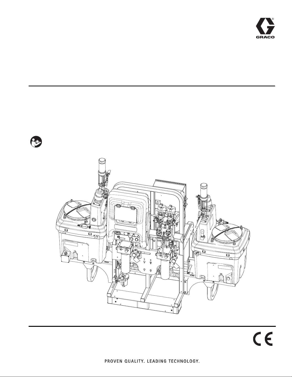
XM Plural-Component
313289S
Sprayers
For spraying two-component epoxy and urethane protective coatings in hazardous and
non-hazardous locations. For professional use only.
EN
Important Safety Instructions
Read all warnings and instructions in this
manual. Save these instructions.
See pages 7 and 8 for model information and
agency approvals.
See page 85 for maximum working pressure.
ti21272a
Page 2

Contents
Related Manuals . . . . . . . . . . . . . . . . . . . . . . . . . . . 3
Warnings . . . . . . . . . . . . . . . . . . . . . . . . . . . . . . . . . 4
Models . . . . . . . . . . . . . . . . . . . . . . . . . . . . . . . . . . . 7
Overview . . . . . . . . . . . . . . . . . . . . . . . . . . . . . . . . . . 9
Isocyanate Hazard . . . . . . . . . . . . . . . . . . . . . . . 9
Material Self-Ignition . . . . . . . . . . . . . . . . . . . . . . 9
Moisture Sensitivity of Isocyanates . . . . . . . . . . . 9
Components A and B . . . . . . . . . . . . . . . . . . . . 10
Changing Materials . . . . . . . . . . . . . . . . . . . . . . 10
Before Repair . . . . . . . . . . . . . . . . . . . . . . . . . . . . . 11
Location . . . . . . . . . . . . . . . . . . . . . . . . . . . . . . 11
Grounding . . . . . . . . . . . . . . . . . . . . . . . . . . . . . 11
Proper Lifting of Sprayer . . . . . . . . . . . . . . . . . . 11
Pressure Relief Procedure . . . . . . . . . . . . . . . . 12
Flush Before Using Equipment . . . . . . . . . . . . . 13
Flush . . . . . . . . . . . . . . . . . . . . . . . . . . . . . . . . . . . . 14
Flush Mixed Material . . . . . . . . . . . . . . . . . . . . . 14
Empty and Flush Entire System (new sprayer or end
of job) . . . . . . . . . . . . . . . . . . . . . . . . . . . . . 16
Shutdown Entire System . . . . . . . . . . . . . . . . . . . 18
Cleaning Procedure . . . . . . . . . . . . . . . . . . . . . . . . 18
XM Setup and Troubleshooting Guide . . . . . . . . 19
Troubleshooting . . . . . . . . . . . . . . . . . . . . . . . . . . 20
Alarms . . . . . . . . . . . . . . . . . . . . . . . . . . . . . . . . . . 23
View Alarms . . . . . . . . . . . . . . . . . . . . . . . . . . . 23
Diagnose Alarms . . . . . . . . . . . . . . . . . . . . . . . . 23
Clear Alarms . . . . . . . . . . . . . . . . . . . . . . . . . . . 23
Repair . . . . . . . . . . . . . . . . . . . . . . . . . . . . . . . . . . . 31
Replace Air Filter Element . . . . . . . . . . . . . . . . 31
User Interface/Control Box . . . . . . . . . . . . . . . . 32
Air Controls . . . . . . . . . . . . . . . . . . . . . . . . . . . . 40
Fluid Control Assembly . . . . . . . . . . . . . . . . . . . 42
Sensors . . . . . . . . . . . . . . . . . . . . . . . . . . . . . . . 43
Pump Assembly . . . . . . . . . . . . . . . . . . . . . . . . 44
Solvent Pump . . . . . . . . . . . . . . . . . . . . . . . . . . 46
Fluid Heaters . . . . . . . . . . . . . . . . . . . . . . . . . . . 46
Electrical Schematics . . . . . . . . . . . . . . . . . . . . . . 47
Simplified Electrical Schematic, XM Sprayer with
Alternator . . . . . . . . . . . . . . . . . . . . . . . . . . 47
Detailed Electrical Schematic, XM Sprayer with
Alternator (page 1) . . . . . . . . . . . . . . . . . . . 49
Simplified Electrical Schematic, XM Sprayer with
Wall Power . . . . . . . . . . . . . . . . . . . . . . . . . 51
Detailed Electrical Schematic, XM Sprayer with Wall
Power (page 1) . . . . . . . . . . . . . . . . . . . . . . 53
Junction Box Wiring Schematics . . . . . . . . . . . . . 55
Fluid Heaters . . . . . . . . . . . . . . . . . . . . . . . . . . . 55
Hopper Heaters . . . . . . . . . . . . . . . . . . . . . . . . . 56
Parts . . . . . . . . . . . . . . . . . . . . . . . . . . . . . . . . . . . . 58
Control Box (255771) Parts . . . . . . . . . . . . . . . . 70
Junction Box (256540) Parts . . . . . . . . . . . . . . . 75
Fluid Control Assembly Parts . . . . . . . . . . . . . . 76
Air Inlet Manifold (255762) Parts . . . . . . . . . . . . 77
Accessories and Kits . . . . . . . . . . . . . . . . . . . . . . . 80
Dimensions . . . . . . . . . . . . . . . . . . . . . . . . . . . . . . . 82
Technical Data . . . . . . . . . . . . . . . . . . . . . . . . . . . . 85
Graco Standard Warranty . . . . . . . . . . . . . . . . . . . 86
Graco Information . . . . . . . . . . . . . . . . . . . . . . . . . 86
2 313289S
Page 3

Related Manuals
Manuals are available at www.graco.com.
Component Manuals in U.S. English:
Manual Description
312359
313292
311762
311238
312747
309524
312145
312769
312794
406699
406739 Desiccant Kit Instructions-Parts
XM Plural-Component Sprayers
Operation
XM Plural-Component OEM Sprayers
Instructions-Parts
Xtreme
Instructions-Parts
NXT
Double Wall Hopper Kit
Instructions-Parts
Viscon
XTR
Instructions-Parts
Feed Pump and Agitator Kits
Instructions-Parts
Merkur
Instructions-Parts
7-Gallon Hopper Installation Kit
Instructions-Parts
®
Displacement Pumps
™
Air Motor Instructions-Parts
®
HP Heater Instructions-Parts
™
5 and XTR™ 7 Spray Guns
®
Pump Assembly
Related Manuals
406690 Caster Kit Instructions-Parts
406691 Hose Rack Kit Instructions-Parts
313258
313259
312770
312749
313293
313342
313343
Electric Heated Hose Power Supply Kit
Instructions-Parts
Hopper or Hose Heat Circulation Kit
Instructions-Parts
Lower Strainer and Valve Kit
Instructions-Parts
XM Mix Manifold Kit
Instructions-Parts
Alternator Conversion Kits
Instructions-Parts
Dosing Valve Repair Kit
Instructions-Parts
High Flow Severe Duty Shutoff Check
Valve Repair Kit Instructions-Parts
313289S 3
Page 4
Warnings
Warnings
The following warnings are for the setup, use, grounding, maintenance, and repair of this equipment. The exclamation point symbol alerts you to a general warning and the hazard symbol refers to procedure-specific risk. Refer back
to these warnings. Additional, product-specific warnings may be found throughout the body of this manual where
applicable.
WARNING
WARNINGWARNINGWARNING
FIRE AND EXPLOSION HAZARD
Flammable fumes, such as solvent and paint fumes, in work area can ignite or explode. To help prevent
fire and explosion:
• Use equipment only in well ventilated area.
• Eliminate all ignition sources; such as pilot lights, cigarettes, portable electric lamps, and plastic drop
cloths (potential static arc).
• Keep work area free of debris, including solvent, rags and gasoline.
• Do not plug or unplug power cords, or turn power or light switches on or off when flammable fumes
are present.
• Ground all equipment in the work area. See Grounding instructions.
• Use only grounded hoses.
• Hold gun firmly to side of grounded pail when triggering into pail.
• If there is static sparking or you feel a shock, stop operation immediately. Do not use equipment
until you identify and correct the problem.
• Keep a working fire extinguisher in the work area.
• Do not connect USB device in explosive atmospheres.
SPECIAL CONDITIONS FOR SAFE USE
• To prevent the risk of electrostatic sparking, the equipment’s non-metallic parts must be cleaned
with only a damp cloth.
• Refer to the Viscon HP Heater manual for special conditions for safe use.
ELECTRIC SHOCK HAZARD
Improper grounding, setup, or usage of the system can cause electric shock.
• Turn off and disconnect power at main switch before disconnecting any cables and before servicing
equipment.
• Connect only to grounded power source.
• All electrical wiring must be done by a qualified electrician and comply with all local codes and
regulations.
4 313289S
Page 5
Warnings
WARNING
INTRINSIC SAFETY
Intrinsically safe equipment that is installed improperly or connected to non-intrinsically safe equipment
will create a hazardous condition and can cause fire, explosion, or electric shock. Follow local regulations and the following safety requirements.
• Only models with model number XM_D_ _ or XM_E_ _, and packaged models with part numbers
ending in 00-13, 17-23, 27-29, 31, utilizing the air-driven alternator are approved for installation in a
Hazardous (explosive atmosphere) Location - see Approvals:, page 8. Only the models stated
above meet all local safety fire codes including NFPA 33, NEC 500 and 516, and OSHA 1910.107.
To help prevent fire and explosion:
• Do not install equipment approved only for a non-hazardous location in a hazardous location.
See model ID label for intrinsic safety rating of your model.
• Do not substitute system components as this may impair intrinsic safety.
• Equipment that comes in contact with the intrinsically safe terminals must be rated for Intrinsic
Safety. This includes DC voltage meters, ohmmeters, cables, and connections. Remove the unit
from the hazardous area when troubleshooting.
• Do not connect, download, or remove USB device unless unit is removed from the hazardous
(explosive atmosphere) location.
• If explosion-proof heaters are used, ensure wiring, wiring connections, switches, and electrical distribution panel all meet flame-proof (explosion-proof) requirements.
SKIN INJECTION HAZARD
High-pressure fluid from gun, hose leaks, or ruptured components will pierce skin. This may look like just
a cut, but it is a serious injury that can result in amputation. Get immediate surgical treatment.
• Do not point gun at anyone or at any part of the body.
• Do not put your hand over the spray tip.
• Do not stop or deflect leaks with your hand, body, glove, or rag.
• Do not spray without tip guard and trigger guard installed.
• Engage trigger lock when not spraying.
•Follow Pressure Relief Procedure in this manual, when you stop spraying and before cleaning,
checking, or servicing equipment.
PRESSURIZED EQUIPMENT HAZARD
Fluid from the gun/dispense valve, leaks, or ruptured components can splash in the eyes or on skin and
cause serious injury.
•Follow Pressure Relief Procedure in this manual, when you stop spraying and before cleaning,
checking, or servicing equipment.
• Tighten all fluid connections before operating the equipment.
• Check hoses, tubes, and couplings daily. Replace worn or damaged parts immediately.
MOVING PARTS HAZARD
Moving parts can pinch or amputate fingers and other body parts.
• Keep clear of moving parts.
• Do not operate equipment with protective guards or covers removed.
• Pressurized equipment can start without warning. Before checking, moving, or servicing equipment,
follow the Pressure Relief Procedure in this manual. Disconnect power or air supply.
313289S 5
Page 6
Warnings
WARNING
EQUIPMENT MISUSE HAZARD
Misuse can cause death or serious injury.
• Do not operate the unit when fatigued or under the influence of drugs or alcohol.
• Do not exceed the maximum working pressure or temperature rating of the lowest rated system
component. See Technical Data in all equipment manuals.
• Use fluids and solvents that are compatible with equipment wetted parts. See Technical Data in all
equipment manuals. Read fluid and solvent manufacturer’s warnings. For complete information
about your material, request MSDS forms from distributor or retailer.
• Check equipment daily. Repair or replace worn or damaged parts immediately with genuine manufacturer’s replacement parts only.
• Do not alter or modify equipment.
• Use equipment only for its intended purpose. Call your distributor for information.
• Route hoses and cables away from traffic areas, sharp edges, moving parts, and hot surfaces.
• Do not kink or over bend hoses or use hoses to pull equipment.
• Keep children and animals away from work area.
• Comply with all applicable safety regulations.
TOXIC FLUID OR FUMES HAZARD
Toxic fluids or fumes can cause serious injury or death if splashed in the eyes or on skin, inhaled, or
swallowed.
• Read MSDS’s to know the specific hazards of the fluids you are using.
• Store hazardous fluid in approved containers, and dispose of it according to applicable guidelines.
• Always wear impervious gloves when spraying or cleaning equipment.
BURN HAZARD
Equipment surfaces and fluid that’s heated can become very hot during operation. To avoid severe
burns, do not touch hot fluid or equipment. Wait until equipment/fluid has cooled completely.
PERSONAL PROTECTIVE EQUIPMENT
You must wear appropriate protective equipment when operating, servicing, or when in the operating
area of the equipment to help protect you from serious injury, including eye injury, inhalation of toxic
fumes, burns, and hearing loss. This equipment includes but is not limited to:
• Protective eyewear
• Clothing and respirator as recommended by the fluid and solvent manufacturer
•Gloves
• Hearing protection
6 313289S
Page 7
Models
Models
XM sprayers are not approved for use in hazardous
locations unless the base model, all accessories, all
kits, and all wiring meet local, state, and national
codes.
Check the identification plate (ID) for the 6-digit part number of the sprayer. Use the following matrix to define the
construction of the sprayer, based on the six digits. For example, Part XM1A00 represents an XM Plural-Component
sprayer (XM); 5200 psi pump set with pump filters (1); wall power supply, no heaters, no junction box, and is not
approved for hazardous areas (A); with no additional kits (00).
NOTE:
Some configurations in the following matrix cannot be built. Consult with distributor or Graco representative.
To order replacement parts, see Parts section in this manual. The digits in the matrix do not correspond to the Ref.
Nos. in the Parts drawings and lists.
XM 1 A
First and
Second
Digits
XM
(plural com-
ponent
sprayer
mounted
on a frame)
(See Table 1 for lower models) Kit Choice
Pump Set
(hose/gun)
1 5200 psi
2 5200 psi B
3 6300 psi
4 6300 psi D
5 5200 psi
6 5200 psi
7 6300 psi
8 6300 psi
Third Digit Fourth Digit
System Choice
Pump
Filters
✔
✔
✔✔
✔✔
Remote
Manifold
✔
✔
Control
Box
Wall Power
A
Supply NE
Wall Power
Supply
Wall Power
C
Supply
IS/
Alternator EH
IS/
E
Alternator
Fluid
Heaters
Location Category Key:
Junction
Box
✔✔
✔
✔
Location
Category
Approvals
(See page 8
for approvals)
CE, FM,
FM
c
NE CE, FM,
c
FM
NE CE, FM,
c
FM
CE, FM,
FM
c,
Ex
EH
CE, FM,
FM
c,
Ex
00
Fifth and
Sixth
Digits
Additional
Kit
See Table
2 for
selections
NE Not for use in European explosive atmosphere locations or hazardous locations.
EH For use in explosive atmospheres and hazardous locations
313289S 7
.
Page 8
Models
Approvals:
See appropriate column on page 7
.
XM _ A_ _
XM _ B_ _
XM _ C_ _
Intrinsically safe for Class I, Div 1, Group D, T2
Class I, Division 1, Group D, T2
Ta = 0°C to 54°C
See Special Conditions for Safe Use in Warnings, page 4.
XM _ D_ _
XM _ E_ _
FM09ATEX0015X
II 2 G
Ex d ia px IIA T2 Tamb = 0ºC to 54ºC
Table 1: Lower Models and Corresponding Identification Codes
System Pressure
Code
(MPa, bar)
1 or 5 5200 psi (35, 350)
Pump
Filters
✔
A Lower
(see manual 311762)
L250C4 L220C4
(see manual 311762)
2 or 6 5200 psi (35, 350) L250C3 L220C3
3 or 7 6300 psi (49, 490)
✔
L180C4 L145C4
4 or 8 6300 psi (49, 490) L180C3 L145C3
Table 2: Additional Kits - Identification Code Index
B Lower
7 Gal.
Hopper
T2 Pump
20 Gal.
Hopper
00
11 1111 1
13 11111
14 111 1 1 1
15 11 1 1 1 1
16 11 1 1 1 1
17 1111 1 1
19 11111 1
21 2222
23 2222
24 222 2 2
25 22 2 2 2
26 22 2 2 2
27 2222 1
29 2222 1
30 2
31 2
32 11
Kit
Hopper
Heater
Kit 240V
Hopper
Fluid
Inlet Kit
Hopper
Universal
Mount Kit
Twistork
Agitator
Kit
Feed Kit
hopper)
(on
5:1 Pump
Feed Kit
(on
hopper)
(Green)
and
Bracket
Kit
7 Gal.
Hopper
(Blue)
and
Bracket
Kit
Drum
Feed Kit
(Dual T2
and
Agitator)
Drum
Feed Kit
(Dual 5:1
and
Agitator)
Heated
Hopper/
Hose
Circulation
Kit
NOTE: See Repair and Spare Parts Reference, page 79, for more information. See Related Manuals, page 3, for
kit manual numbers.
8 313289S
Page 9
Overview
Overview
XM sprayers are not approved for use in hazardous
locations unless the base model, all accessories, all
kits, and all wiring meet local, state, and national
codes. See Models, page 7, to determine the appro-
priate location for your particular model.
Isocyanate Hazard
Spraying materials containing isocyanates creates
potentially harmful mists, vapors, and atomized particulates.
Read material manufacturer’s warnings and material
MSDS to know specific hazards and precautions
related to isocyanates.
Prevent inhalation of isocyanate mists, vapors, and
atomized particulates by providing sufficient ventilation in the work area. If sufficient ventilation is not
available, a supplied-air respirator is required for
everyone in the work area.
To prevent contact with isocyanates, appropriate personal protective equipment, including chemically
impermeable gloves, boots, aprons, and goggles, is
also required for everyone in the work area.
Moisture Sensitivity of Isocyanates
Isocyanates (ISO) are catalysts used in two component
foam and polyurea coatings. ISO will react with moisture
(such as humidity) to form small, hard, abrasive crystals,
which become suspended in the fluid. Eventually a film
will form on the surface and the ISO will begin to gel,
increasing in viscosity. If used, this partially cured ISO
will reduce performance and the life of all wetted parts.
NOTE:
The amount of film formation and rate of crystallization
varies depending on the blend of ISO, the humidity, and
the temperature.
To prevent exposing ISO to moisture:
• Always use a sealed container with a desiccant
dryer in the vent, or a nitrogen atmosphere. Never
store ISO in an open container.
• Keep the ISO lube pump reservoir filled with Graco
Throat Seal Liquid (TSL), Part 206995. The lubricant creates a barrier between the ISO and the
atmosphere.
• Use moisture-proof hoses specifically designed for
ISO, such as those supplied with your system.
• Never use reclaimed solvents, which may contain
moisture. Always keep solvent containers closed
when not in use.
• Never use solvent on one side if it has been contaminated from the other side.
• Always park pumps when you shutdown.
• Always lubricate threaded parts with Part 217374
ISO pump oil or grease when reassembling.
Material Self-Ignition
Some materials may become self-igniting if applied
too thick. Read material manufacturer’s warnings and
material MSDS.
313289S 9
Page 10

Overview
Components A and B
IMPORTANT!
Material suppliers can vary in how they refer to plural
component materials.
Be aware that in this manual:
Component A
Component B
NOTE:
This equipment doses the B component into the A component flow. An integration hose must always be used
after the mix manifold.
Follow these recommendations for reassembly and
setup:
• use at least a 3/8 in. (10 mm) x 25 ft. (7 m) hose.
• install a 24-element static mix tube after the integration hose.
Keep Components A and B Separate
To prevent cross-contamination of the equipment’s
wetted parts, never interchange component A
(resin) and component B (hardener) parts.
refers to resin or major volume.
refers to the hardener or minor volume.
NOTICE
Changing Materials
• When changing materials, flush the equipment multiple times to ensure it is thoroughly clean.
• Always clean the fluid inlet strainers and outlet filter
after flushing. See Flush on page 14.
• Check with your material manufacturer for chemical
compatibility.
• Epoxies often have amines on the B (hardener)
side. Polyureas often have amines on the A (resin)
side.
NOTE:
If the amine will switch between the two sides, see
Flush on page 14.
10 313289S
Page 11
Before Repair
Before Repair
Location
XM sprayers are not approved for use in hazardous
locations unless the base model, all accessories, all
kits, and all wiring meet local, state, and national
codes. See Models, page 7, to determine the appro-
priate location for your particular model.
Grounding
Connect ground wire clamp (FG) to a true earth ground.
If wall power is used to power controls or heaters,
ground electrical connection properly according to local
codes.
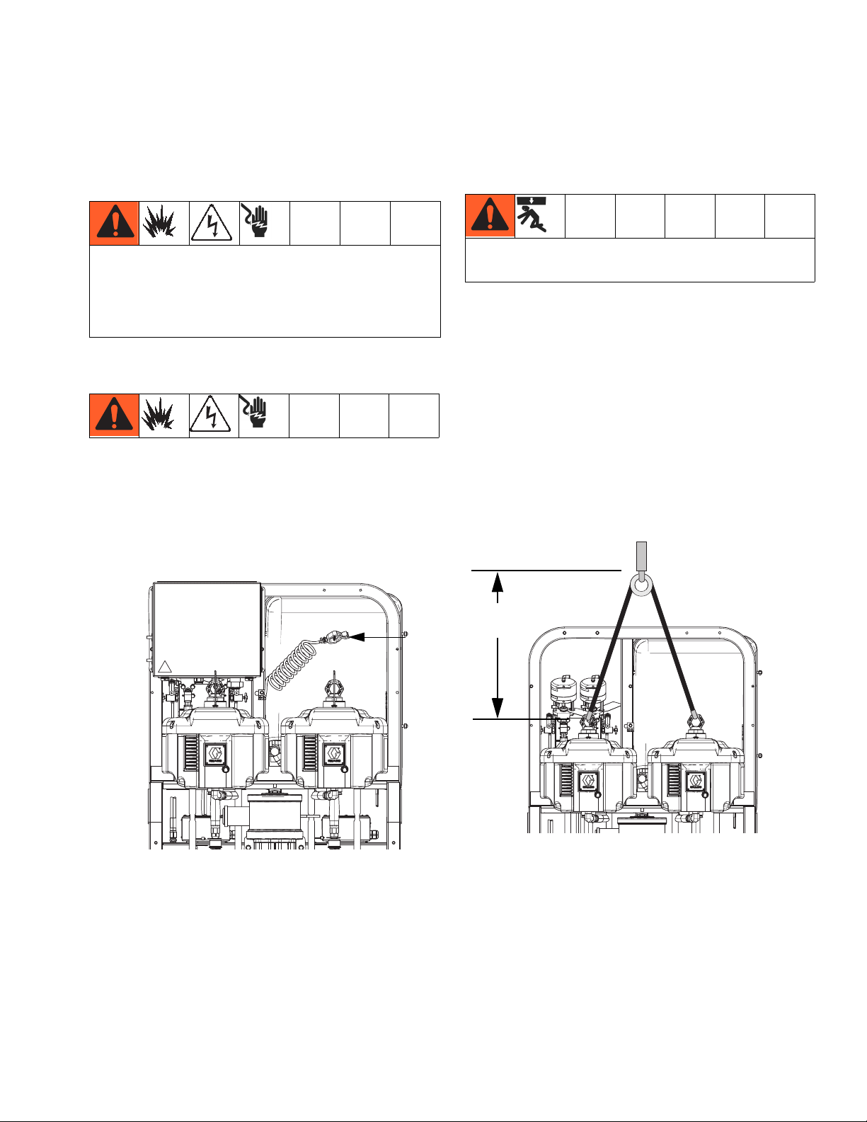
Proper Lifting of Sprayer
Follow instructions to avoid serious injury or damage
to equipment. Never lift with the hopper(s) filled.
Lift Using a Forklift
Power must be off. Sprayer can be raised and moved
using a forklift. Carefully lift the sprayer; make sure it
balances evenly.
Lift Using a Hoist
Sprayer can also be lifted and moved using a hoist.
Connect a bridle swing, hooking an end to each of the
air motor lift rings. Hook the center ring to a hoist Carefully lift the sprayer; make sure it balances evenly.
ti21273a
FG
2.0 ft. (0.61 m)
minimum
ti21274a
313289S 11
Page 12
Before Repair
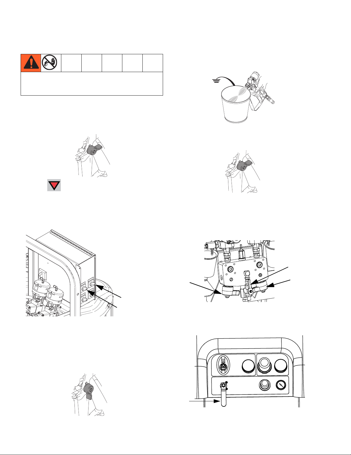
Pressure Relief Procedure
Follow Pressure Relief Procedure when you stop
spraying or dispensing; and before cleaning, checking, servicing, or transporting equipment.
Relieve A and B Fluid Pressure
1. Engage trigger lock.
TI1949a
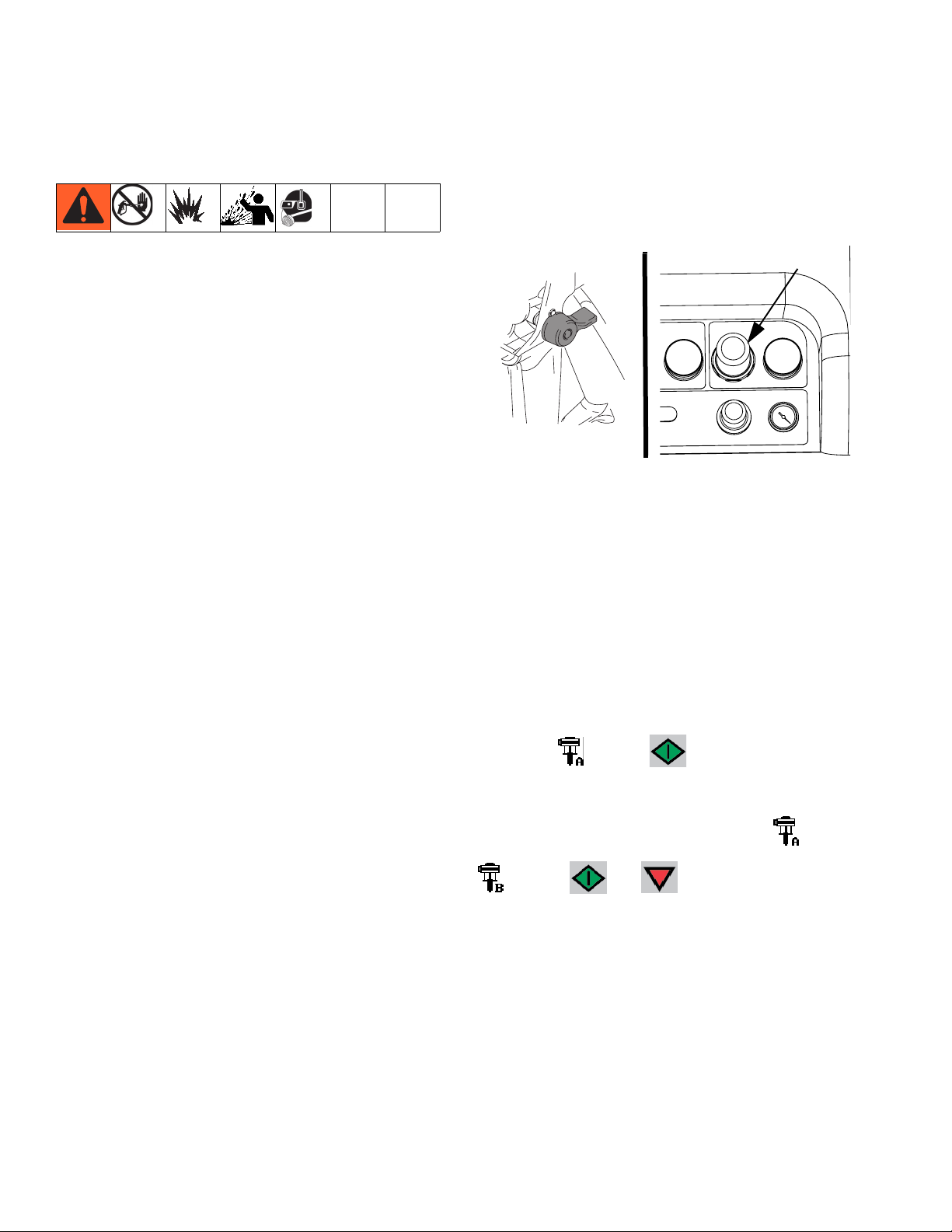
2. Press .
3. If fluid heaters are used, shut them off using the
controls on the heater control box.
7. Hold a metal part of the gun firmly to a grounded
metal pail with a splash guard in place. Trigger gun
to relieve pressure in material hoses.
TI1953a
8. Engage trigger lock.
TI1949a
Relieve Pump Fluid Pressure
4. Shut off feed pumps, if used.
5. Remove spray tip and clean.
6. Disengage trigger lock.
Fluid Heater B
Fluid Heater A
ti21275a
9. Close mix manifold valves (AH, AJ), then open solvent flush valve (AK) on mix manifold.
AK
AH
AJ
Replace with illustration
10. Open solvent pump air control (CB). Use lowest
pressure needed to flush material out of hose.
CB
TI1950a
12 313289S
r_312359_313289_14
Page 13
Before Repair
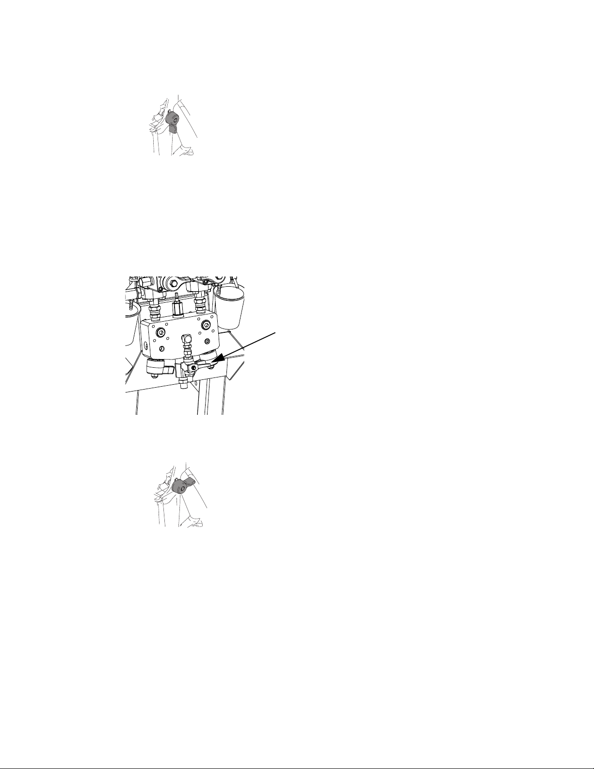
11. Disengage trigger lock.
TI1950a
12. Hold a metal part of the gun firmly to a grounded
metal pail with a splash guard in place. Trigger gun
to flush mixed material out of line with clean solvent.
13. Shut off solvent pump on air control panel.
14. Repeat steps 11 and 12. Then continue to step 15.
15. Close solvent flush valve (AK) on mix manifold.
AK
Flush Before Using Equipment
The equipment was tested with lightweight oil, which is
left in the fluid passages to protect parts. To avoid contaminating your fluid with oil, flush the equipment with a
compatible solvent before use. See Flush on page 14.
Replace with illustration
r_312359_313289_5
16. Release any residual gun pressure and engage trigger lock.
TI1949a
313289S 13
Page 14
Flush
Flush
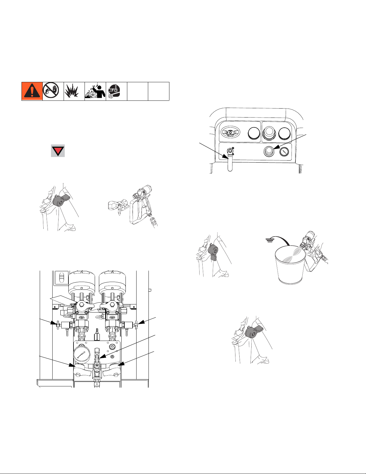
Flush Mixed Material
Flush Mix Manifold
Use Solvent Pump
1. Press to turn off system. Follow Pressure
Relief Procedure, page 12. Engage trigger lock.
Remove spray tip.
TI1949a
TI1948a
4. Open solvent pump air control (CB). Pull out and
slowly turn solvent pump air regulator (CG) clockwise to increase air pressure. Use lowest possible
pressure.
CG
CB
r_312359_312359_3
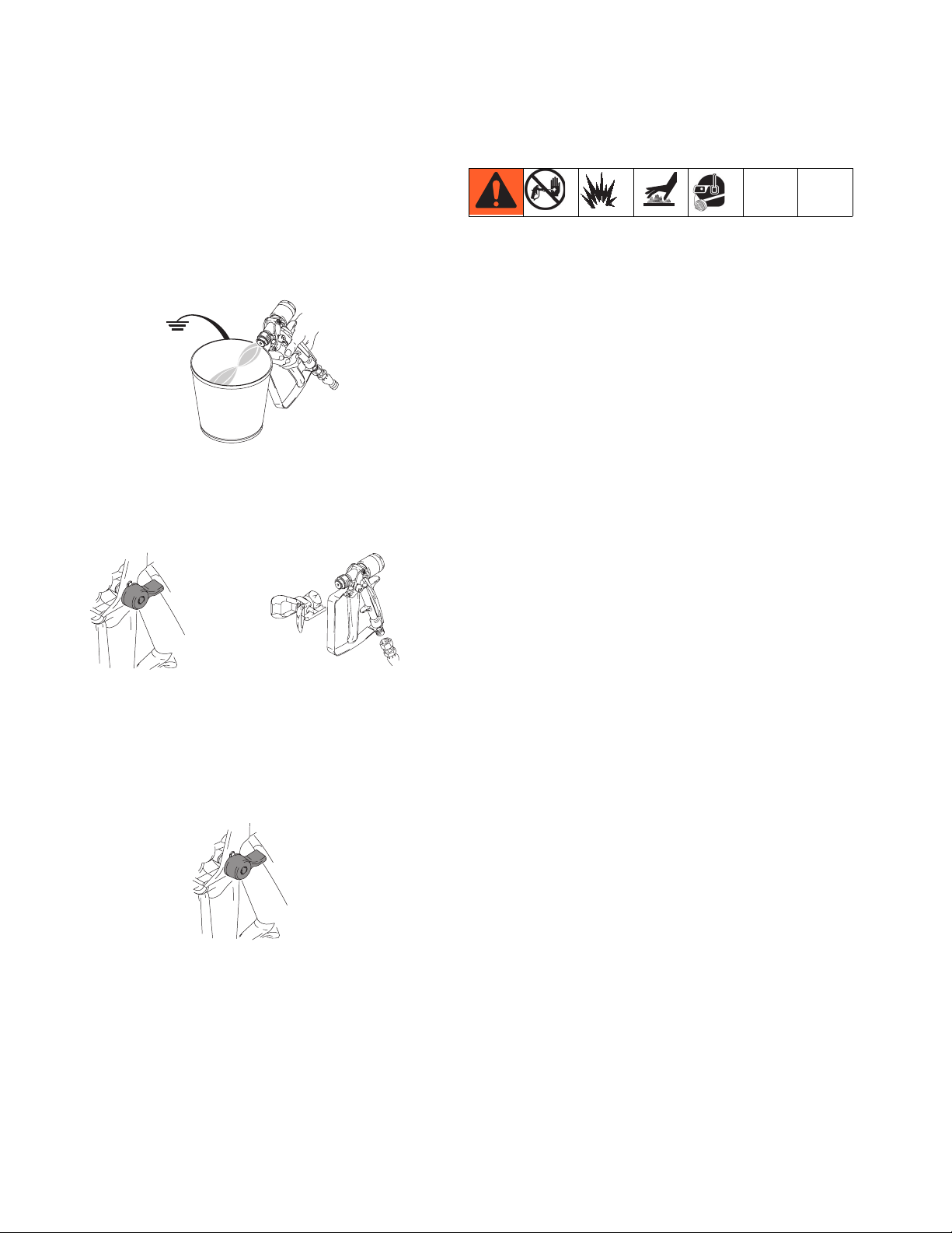
5. Disengage trigger lock. Hold a metal part of the gun
firmly to a grounded metal pail with a splash guard
in place.Use a pail lid with a hole in it to dispense
through. Be careful to keep fingers away from the
front of the gun. Trigger gun until solvent appears.
4)!
2. Close sampling valves (AE, AF) and mix manifold
valves (AH, AJ).
r_xm1a00_313289_12f
AE
AF
AK
AJ
AH
3. Open solvent shutoff valve (AK) at mix manifold.
TI195oa
TI1953a
6. Engage trigger lock.
TI1949a
14 313289S
Page 15
Flush
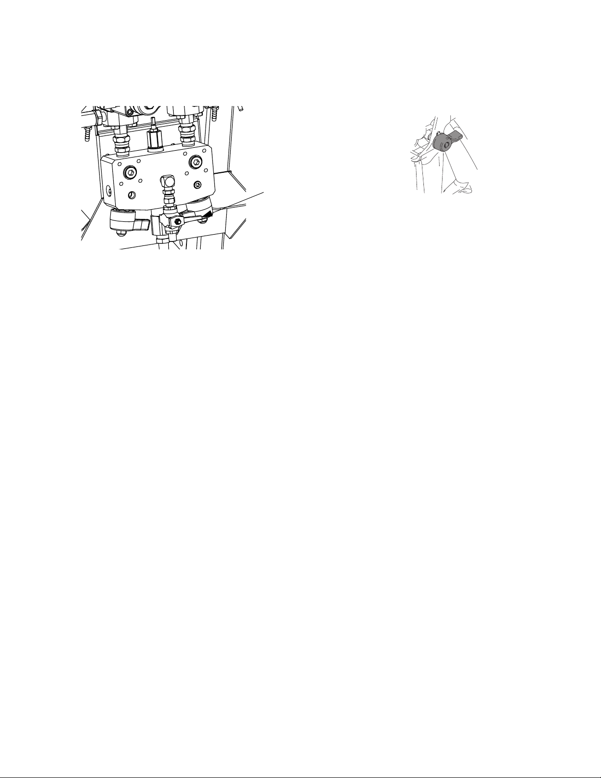
7. Close solvent pump air valve (CB) and solvent shutoff valve (AK) at mix manifold.
r_312359_313289_5
AK
8. Follow Pressure Relief Procedure, page 12.
9. Engage trigger lock.
TI1949a
10. Disassemble and clean spray tip with solvent by
hand. Reinstall on the gun.
313289S 15
Page 16
Flush
Empty and Flush Entire System (new sprayer or end of job)
NOTE:
• If system includes heaters and heated hose, turn
them off and allow to cool before flushing. Do not
turn on heaters until fluid lines are clear of solvent.
• Use the lowest possible pressure when flushing to
avoid splashing.
• Before color change or shutdown for storage, flush
at a higher flow rate and for a longer time.
• To flush only mix manifold, see Flush Mix Manifold
procedure page 14.
Guidelines
Flush new systems if coating materials will be contaminated by 10W oil.
Flush system when any of the following situations occur.
Flushing will help prevent materials from clogging the
line between hoppers and pump inlets.
• anytime sprayer will not be used for more than
one week
• if materials used will settle
• if using thixotropic resins that require agitation
Procedure
1. Follow Pressure Relief Procedure, page 12, and
Flush Mixed Material, page 14, as required.
Engage trigger lock. Turn main pump air regulator
(CD) fully counter-clockwise to shut off.
CD
air regulator
TI1949a
r_312359_313289_13
NOTE:
When flushing coating materials remove pump fluid filters, if installed, and soak in solvent to decrease cleaning time. Proceed with Step 2. If flushing a new system,
leave filters in place.
2. Move circulation return lines to separate fluid containers to pump remaining fluid out of system.
3. Increase main pump air regulator (CD) pressure to
30 psi (21 kPa, 2.1 bar).
4. Select . Press .
NOTE:
When running pumps independently set to or
. Press and as needed to clean.
NOTE:
If sprayer does not start with static pressure, increase
air pressure by 10 psi (69 kPa, 0.7 bar) increments. To
avoid splashing do not exceed 40 psi (28 kPa, 2.8 bar).
16 313289S
Page 17
Flush
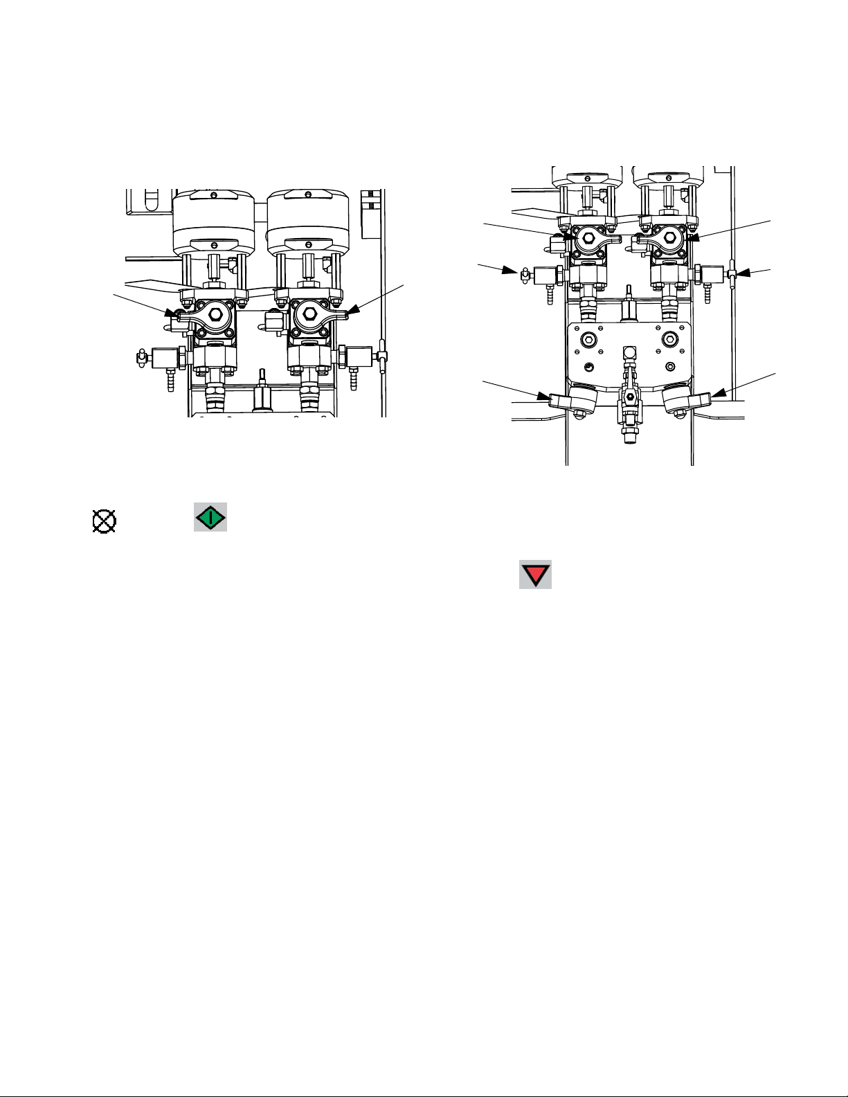
5. Open recirculation valves (AC, AD) for respective
pump dispense side. Run pumps until the A and B
reservoirs are empty. Salvage the material in separate, clean containers.
AC
r_312359_313289_6
AD
NOTE:
When priming or flushing the pumps, it is normal to get
cavitation or pump runaway alarms. Clear the alarms
9. Close recirculation valves (AC, AD) and open mix
manifold valves (AH, AJ). Dispense fresh solvent
through mix manifold valves and out gun.
AC
AE
AF
AH
r_312359_313289_7
10. Close mix manifold valves (AH, AJ).
AD
AJ
, and press again as necessary. These
alarms prevent excessive pump speeds that can damage pump packings.
6. Wipe the reservoirs clean, then add solvent to each.
Move circulation lines to waste containers.
7. Repeat Step 4 to flush through each side until clean
solvent exits recirculation hose.
8. Stop and move recirculation hoses back to reser-
voirs. Continue recirculating until machine is thoroughly flushed.
11. Slowly open sampling valves (AE, AF) to flush solvent through until clean. Close sampling valves.
Press .
12. Follow Pressure Relief Procedure, page 12.
13. Remove pump fluid filters, if installed, and soak in
solvent. Clean and replace filter cap. Clean filter
o-rings and leave out to dry. Do not leave o-rings in
solvent.
14. Close main air valve (E).
NOTE:
Always leave some type of fluid, such as solvent or oil,
in the system to prevent scale build up. This build up
can flake off later. Do not use water.
313289S 17
Page 18
Shutdown Entire System
Shutdown Entire System
Follow this procedure before prolonged shutdown or
before servicing equipment.
1. Follow Pressure Relief Procedure, page 12. Place
gun over pail. Trigger gun; wait until pumps are
down.
TI1953a
2. Engage trigger lock, turn off air regulator, and close
main air shutoff valve. Remove spray tip.
Cleaning Procedure
1. Ensure all equipment is grounded. See Grounding,
page 11.
2. Turn off all heaters and allow equipment to cool.
3. Flush mixed material. See Flush Mixed Material,
page 14.
4. Relieve pressure. See Pressure Relief Procedure,
page 12.
5. Shutdown sprayer and turn off all power. See Shut-
down Entire System, page 18.
6. Ensure the area where the sprayer will be cleaned
is well ventilated; and remove all ignition sources.
7. Clean external surfaces using only a rag soaked in
solvent that is compatible with the spray material
and the surfaces being cleaned.
8. Allow enough time for solvent to dry before using
sprayer.
TI1949a
4)!
TI1948a
3. Follow flushing procedure, see Flush on page 14.
4. Follow Pressure Relief Procedure, page 12.
Engage trigger lock.
TI1949a
5.
For prolonged shutdown (one week or longer):
• Follow flushing procedure, see Empty and
Flush Entire System (new sprayer or end of
job) on page 16.
• Cap fluid outlets to keep solvent in the lines.
• Fill pump A and B packing nuts with throat seal
liquid (TSL).
18 313289S
Page 19

XM Setup and Troubleshooting Guide
XM Setup and Troubleshooting Guide
The following setup information will help ensure the system is setup properly. See the XM repair-parts manual for troubleshooting and repair instructions.
Grounding
• Ground system to a true earth ground.
• Ensure incoming power is grounded.
Air Supply
• Use at least a 3/4 in. (19mm) ID air hose, no longer
than 50 feet (15m).
• Ensure the first gauge (supply) stays above 80 psi
(0.55 MPa, 5.5bar) while spraying.
• Ensure that the pump spray pressure regulator is set to
at least 35 psi (2.4 bar) for spraying.
• Ensure that the solenoid air filter/regulator behind the
air panel is set to at least 80-85 psi.
• Check that the air filter element in the solenoid air filter/regulator behind the air panel is clean.
Calibration
• Adjust the B side fluid restrictor so that the calibration
bar graph averages center to right middle. This means
that the “B” dosing valve is open 25% to 75% of the
time.
• Ensure dosing valve needle packing nuts are not
adjusted too tight. They should be snug when there is
no fluid pressure on the valve.
• If feed pumps are used, don’t use more than 250psi
(17 bar). Excess pressure adds double the amount of
pressure on only the upstroke of the XM metering
pump.
Motor Icing
• Ensure that the NXT motor De-Ice bleed valves are
open to bleed warm air across the ice.
• Ensure that the motor is left active when not spraying
to keep the internal bleed air working. Leave the motor
active in Spray mode or Manual mode to keep the
bleed air on.
Restrictions or Lost Pressure
• Always use filter screens in the XM pump lowers. Filter
style pumps come with 60 mesh screens. Optional 30
mesh elements are also supplied.
• Always use a gun filter. 60 mesh is provided in the gun.
Check that the static mixer is clean.
• Early mix manifolds (2009) had a 40 mesh screen on
the B side. The screen could plug with materials that
have filled ‘B’ side fluids.
Remote Mix Manifold Applications
Ensure remote mix manifold outlet kit is installed. See XM
Repair parts manual. The kit includes outlet check valves
which isolate the pump pressure sensors from the outlet
hoses, and includes a ‘B’ side restrictor valve for the
machine outlet.
NOTE: Early remote manifold machines didn’t include
the ‘B’ restrictor valve from the factory.
• Ensure that the ‘A’ and ‘B’ outlet hose sizes volume
balanced close to the mix ratio. Unbalanced hose sizes
can cause off ratio slugs at the mix manifold during
pressure and/or flow transitions. See XM Mix Manifold
Kits manual.
• If a minimum of integration and mix hose is used,
ensure that “Fast Dosing” is selected in the setup
screens.
Air motors accumulate ice in the exhaust valving and muffler under hot and humid conditions or under cold ambient
conditions. It can cause pressure loss or motor stalling.
• The ‘B’ fluid pressure should always be 15% to 30%
higher than ‘A’ pressure.
•
A larger pressure difference indicates ‘A’ motor icing.
• A smaller or negative pressure difference indicates ‘B’
motor icing.
313289S 19
Software Version
• Ensure all modules in the system use software from
same token. Different software versions may not be
compatible.
• The latest software version for each system can be
found at Tech Support at www.graco.com.
Page 20

Troubleshooting
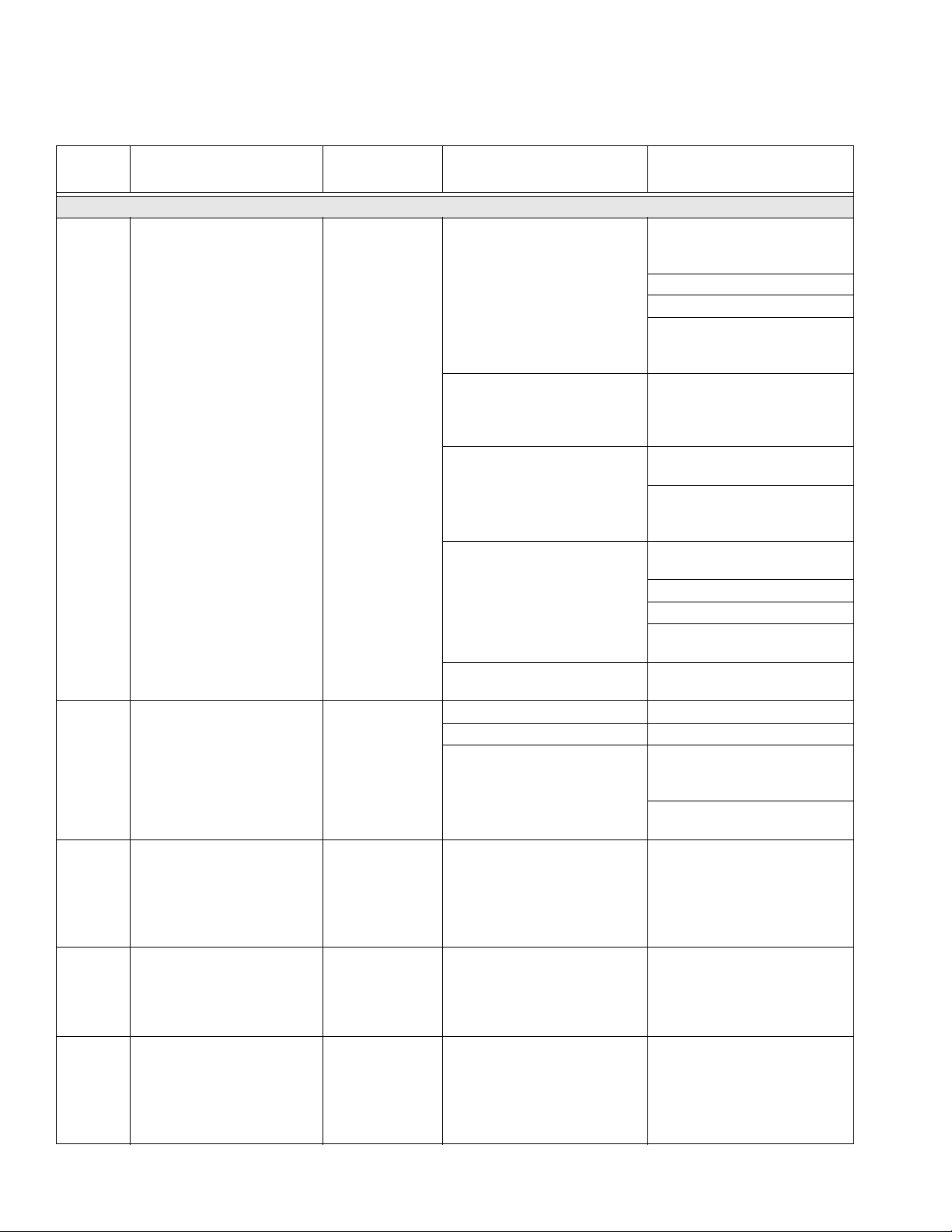
Troubleshooting
NOTE:
The sprayer operates using air pressure. Many problems are caused by inadequate air supply. The inlet air
pressure gauge cannot drop below 50 psi (0.35 MPa,
3.5 bar) while running.
Problem Cause Solution
Display not lit on system with alternator
power supply.
No electric power.
Display not lit on system with alternator
power. Green light is present on FCM
(218) and USB (219), but no green light is
present on back of display module (204).
Display not lit on system with wall power
supply. No green light present on back of
display module (204).
Display not lit on system with wall power
supply. Green light is present on back of
display module (204).
Air valve not turned on. Turn on main air valve to system.
Air supply pressure too low. Increase pressure to 30 psi (0.21 MPa,
Air supply filters plugged. Inlet manifold
filter (604) or air regulator (344) filter
plugged.
Turbine air regulator (277) set too low. Adjust to 18 +/- 1 psi (12.6 +/- 10 kPa,
Alternator turbine failure. Repair or replace turbine. Page 38.
Power supply not connected to main
board.
Display board failure. Replace display board. Page 36.
Faulty CAN cable (268). Or CAN cable is
disconnected.
Faulty display module. Replace display module. See User Inter-
No electric power. Disconnect “off” or
breaker “open.”
No green lights present on display, FCM,
or USB module.
No display power through CAN cable
(266). Green light in present on FCM
(218), but is not present on USB module
(219).
Green light is present on USB module
(219).
Display module failed. Replace display module. See User Inter-
NOTE:
If an error code displays, see Alarms on page 23.
2.1 bar) or greater.
Clean filter bowls; replace filter elements.
Page 31.
1.26 +/- 0.07 bar).
Check power connections to main board.
See Electrical Schematics, starting on
page 47.
Check cable and replace. See Alternator
Assembly, page 72.
face/Control Box, page 32.
Reset main disconnect and breaker.
Check for 24 Vdc on J1, pins 2 and 3, of
power supply. See Electrical Schemat-
ics, starting on page 47. If there is not 24
Vdc, replace with 15V747.
Check CAN cable. Replace if necessary.
See Wall Power Supply Assembly,
page 73.
Check CAN cable (274). Replace if necessary. See Wall Power Supply Assem-
bly, page 73.
face/Control Box, page 32.
20 313289S
Page 21

Troubleshooting
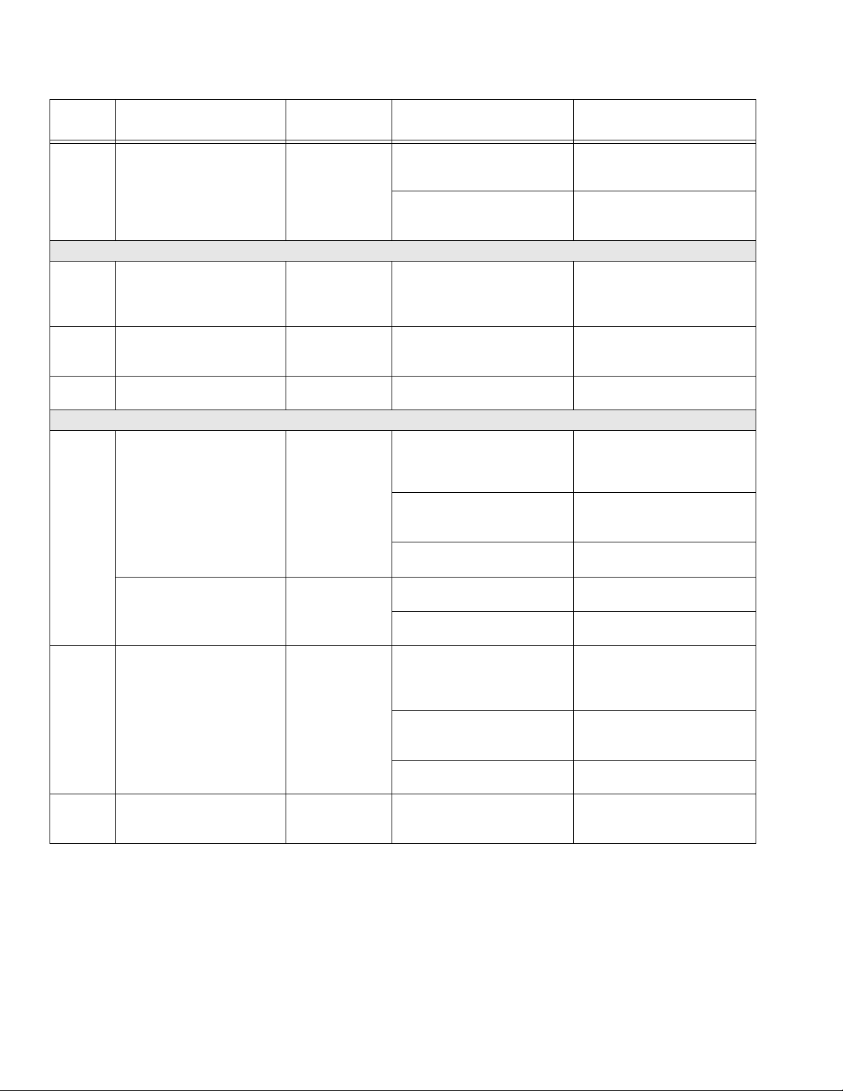
Problem Cause Solution
Pumps do not run when Run Mode is
selected and the blue LED is illuminated.
Pump Test completes without error, but A
or B component has more than 750cc of
fluid in beaker.
Batch Test completes without error, but A
or B component has more fluid in beaker
than displayed on screen.
Sprayer does not start when start button
is pressed.
Fluid valves leaking. Loose or worn packings. Tighten packing nut. If leak continues,
Paint does not cure consistently. Ratio not set correctly. Check that correct ratio is set and set by
Air pressure to pumps too low Increase pressure to 50 psi (0.35 MPa,
3.5 bar) or greater.
Air pilot lines are obstructed Check pilot lines for kinks or pinches.
Solenoid valve stuck. Actuate solenoid manually, if it does not
operate, replace solenoid. Page 32.
Air pilot valve(s) to motor stuck. Replace valve(s). Page 42.
Metering valve(s) not opening. Service or replace valve(s). Page 42.
Air motor stalled. See manual 311238.
Incorrect pumps were selected in System
Setup screens.
Air is trapped in fluid due to excessive
agitation, circulation, and heat. Fluid is
measured by volume when it is compressed under pressure.
See causes for previous pump test problem.
Faulty start switch or wire harness. Check start switch and wiring harness
Faulty stop switch or wiring harness. Check stop switch and wiring harness
See Appendix A in manual 312359.
Repeat Pump Test with fresh fluid.
If the specific gravity of each fluid is
known, check samples by weight (750cc
x specific gravity equals weight in grams).
If weight is correct, extra volume in beaker is air.
See solutions for previous pump test
problem.
continuity; switch is normally open circuit.
See Electrical Schematics, starting on
page 47.
continuity; stop switch is normally closed
circuit. See Electrical Schematics, starting on page 47.
replace packings.
volume. See manual 312359.
Material not mixing correctly. Test pump. Make sure mixer is clean;
flush as needed. See manual 312359.
Position mixer after integrator hose.
Poor spray pattern.
Also, see “System runs erratically” below.
Material not properly conditioned before it
was added to sprayer.
Not using enough integration hose. Add more integration hose.
Fluid pressure too low. Increase pump pressure.
Fluid temperature too low. Increase fluid temperature.
Spray tip dirty or worn. Relieve pressure. Clean or replace tip.
Fluid A or B filters plugged. Clean filters. See pump manual.
Mixer or hoses partially plugged or too
restrictive.
Mix material thoroughly.
Select “fast dosing” in setup.
Follow gun manual instructions.
Inspect parts for cured material. Clean or
replace, or use larger hoses and mixer.
313289S 21
Page 22

Troubleshooting
Problem Cause Solution
System runs erratically. Air filter(s) clogged. Replace elements. Clean. Replace element(s). See page 31.
Air supply hoses undersized. Replace hoses with appropriate size.
Air compressor undersized. Use larger air compressor.
Air supply pressure tank undersized. Use larger pressure tank.
Inlet air pressure gauge drops below 50
psi (0.35 MPa, 3.5 bar) while spraying.
A and/or B air motor has ice. Open air motor de-ice bleed air control.
Pump is binding. Repair lower. See Remove Displace-
Air supply relief valve opens. Air regulator set too high. Lower setting.
Turbine alternator makes high-pitched
whining noise, or quits.
Display module cycles on and off. Turbine is not supplying enough power to
Flow rate too low. Air supply hose is too small or too long. Use 3/4 in. (minimum) ID hose. See
Receive ratio alarm after starting in spray
mode while using remote mix manifold.
Receive ratio alarm while using remote
mix manifold after a significant change in
pressure.
Erratic pressure at spray gun when using
feed pumps.
Turbine bearings worn. (Setting turbine
air regulator too high, wears bearings.)
board.
Inadequate air supply. Use larger CFM compressor.
Air pressure to pumps too low. Increase pressure.
Fluid A or B filters plugged. Clean filters. See pump manual.
Spray tip too small. Relieve pressure. Install larger tip. Follow
Mixer or hoses partially plugged or too
restrictive.
A and B hoses do not fill to correct pressure ratio simultaneously. Therefore,
spray time increases in order to balance
pressure. Ratio screen bar graph stays to
one side until pressure balances.
A and B hoses do not fill to correct pressure ratio simultaneously. Therefore,
spray time increases in order to balance
pressure. Ratio screen bar graph stays to
one side until pressure balances.
Feed pressure is too high. Feed pressure
at metering pump is too high on up
stroke. Doubles the feed pressure to outlet pressure on up stroke only.
See solutions above for system runs
erratically problem.
Allow ice to melt. Dry the compressed air.
Heat the compressed air. Use a smaller
tip and lower flow rate.
ment Pump, page 44.
Replace turbine cartridge. See Alterna-
tor Power Supply Control Components, page 38.
Increase turbine regulator setting to
18 +/- 1 psi (12.6 +/- 10 kPa, 1.26 +/- 0.07
bar). Check voltages on information
screen. 10-14 Vdc when spraying.
Check turbine and electrical control
exhaust air for restrictions.
Replace turbine cartridge. See Alterna-
tor Power Supply Control Components, page 38.
Technical Data, page 85.
gun manual instructions.
Inspect parts for cured material. Clean or
replace, or use larger hoses and mixer.
While in circulation mode, close circulation valves and increase pressure in
hoses until correct spray pressure is
achieved.
Select correct hose size to balance your
volume ratio. See manual 312749.
While in circulation mode, close circulation valves and increase pressure in
hoses until correct spray pressure is
achieved.
Select correct hose size to balance your
volume ratio. See manual 312749.
Change pressure slowly while spraying.
Use lowest feed pressure needed to
maintain feed.
22 313289S
Page 23
Alarms
Alarms
View Alarms
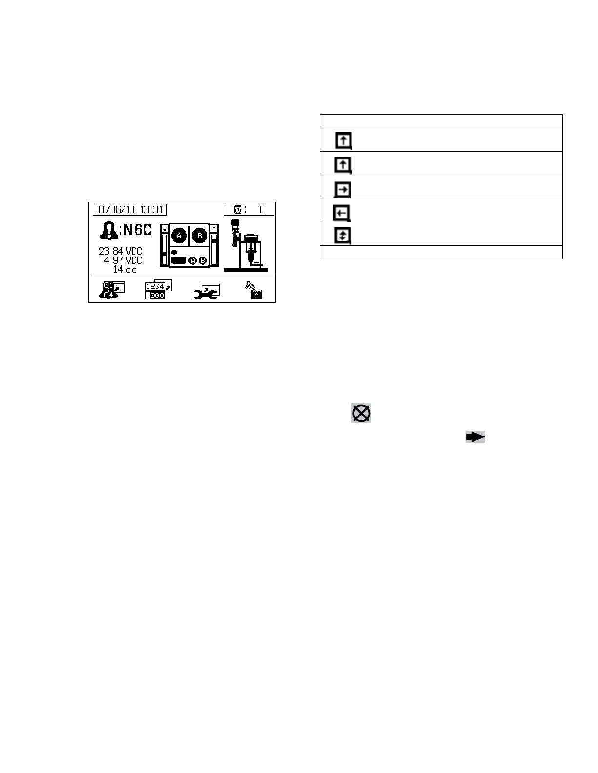
When an alarm occurs the alarm information screen
automatically displays. It shows the current alarm code
along with a bell icon. It also shows the alarm location
with top and side views of the sprayer.
There are two levels of alarms: warnings and advisories.
A bell icon indicates an alarm. A solid bell icon with an
exclamation point and three audible alerts indicate a
warning. And an outlined hollow bell icon and a single
audible alert indicate an advisory.
Advisories are notifications that require attention but not
immediately. Alarms require immediate correction;
therefore, sprayer operation automatically stops.
Icon Function
Moving up
Moving down
Top changeover
Bottom changeover
One reed switch signal is missing
Blank: No reed switch signal
Diagnose Alarms
See Alarm Codes and Troubleshooting for causes
and solutions to each alarm code.
Clear Alarms
Press to clear alarms and advisories. From the
This screen also shows diagnostic information. There
are three lines of data on the left side. The top line
shows the power supply or alternator power supply. This
should be between 23-25 Volts for power supply systems and 10-14 Volts for alternator systems. The middle
line shows the sensor voltage. This should be between
4.9-5.1 Volts.
The center of the screen shows linear sensor vertical
bar graphs and reed switch information. The A side
information is on the left and the B side information is on
the right. Linear sensor position is displayed on the bar
graph that goes up and down when the pump moves.
This bar graph should move from top to bottom to match
each pump stroke.
The state of the two reed switches in each air motor are
shown with the arrow above each vertical bar graph.
alarm information screen, press to return to the
run (fluid control) screen.
313289S 23
Page 24
Alarms
Alarm Codes and Troubleshooting
Alarm
Code Alarm Problem When Active Cause Solution
General Performance Alarms
R4B Ratio High B (Overdose B),
system delivering too much B
component.
R1B Ratio Low B (under dose B);
system delivering not enough
B component.
REC System detected five R4B
(ratio high B) or five R1B
(ratio low B) alarms within five
minutes. Sprayer shuts down
for five minutes to resolve
problem.
FHA
FHB
R2D Dosing sizes are not opti-
System detects pump movement (fluid flow) when valves
are closed.
mized.
Spray B Dosing valve not closing. Perform Pump Test to test for
leakage. See Pump and Metering test in manual 312359.
Loosen valve packing nut.
Check air signal at valve top
Repair valve or air solenoid.
See Replace Solenoid Mod-
ule, page 32.
No B restriction at mix manifold. Increase B Restriction by turn-
ing B restrictor stem clockwise.
See Adjust B Mix Manifold
Restriction in manual 312359.
Pump filter plugged on A side. Clean filter. See manual
311762.
Use alternate 30 mesh screen.
See manual 311762 for part
number.
Inlet air dropping below 80 psi
(0.55 MPa, 5.5 bar) while spraying. B dosing valve not closing
correctly.
Solenoid air regulator set below
80 psi (0.55 MPa, 5.5 bar)
Spray B dosing valve will not open. Check for air signal to valve.
B mix manifold valve closed. Open green mix manifold valve.
Pump filter plugged on B side. Use alternate 30 mesh screen.
Spray See R4B or R1B alarm causes. See R4B or R1B alarm solu-
Spray Recirculation valve or dosing
valve open or leaking for more
than 5 seconds.
Spray Dosing valve is operating near
high or low timing limits.
Check air filters. See Air Con-
trols, page 40.
Use larger air hose.
Use larger compressor.
Use smaller gun tips or less
guns to reduce flow rate.
Adjust air regulator.
See manual 311762 for part
number.
Clean B pump outlet filter. See
manual 311762.
tions. Flush mixed material if
necessary, and purge off-ratio
mixed material in hose.
Close or repair recirculation
valve, and run Pump Test. See
Pump and Metering test in manual 312359. See Mix Manifold
Assembly, page 42.
Adjust mix manifold B restrictor
stem clockwise or counter
clockwise as indicated by bar
graph on restrictor screen. See
Adjust B Mix Manifold Restriction in manual 312359.
24 313289S
Page 25

Alarm
Code Alarm Problem When Active Cause Solution
P4A
P4B
DAA
DAB
DDA
DDB
P1A
P1B
P4R Pressure high. Recirculation Pressure is above maximum
P5R Pressure high. Recirculation Pressure is above maximum
P9A A pump pressure is abnor-
P9B B pump pressure is abnor-
B3A Dosing size A advisory Spray The fluid dosing size is greater
Pressure high Always Fluid pressure is above maxi-
mum.
Pump runaway, above 80
cpm for 10 sec.
Pump cavitation; dives more
than 3/4 of stroke.
Pressure low. Spray, Pump
mally low compared to B
pump pressure.
mally low compared to A
pump pressure.
Always No material in pump or lines; no
fluid restriction.
Always No fluid or valve closed. Refill supply and open inlet
Material is too cold or thick. Increase material temperature
Pump inlet check valve not
closing.
Feed pump not providing material.
Inlet strainer plugged (if used). Check and clean strainer. See
Fluid pressure is below 1000
Test, Leak Test
Spray A air motor is icing up causing
Spray B air motor is icing up causing
psi (7 MPa, 70 bar).
advisory limit of 3000 psi (21
MPa, 210 bar) on A side.
warning limit of 5200 psi (35.9
MPa, 359 bar) on A side.
restriction and lower fluid pressure.
A pump is binding. Repair lower. See Remove
A motor is hanging up. Repair air motor. See Remove
restriction and lower fluid pressure.
B pump is binding. Repair lower. See Remove
than 35 cc when fast dosing is
turned off.
The fluid dosing size is greater
than 20 cc when fast dosing is
turned on.
Decrease main air regulator or
feed pump pressure.
Refill material in tank or hoses;
install fluid tip.
valve.
to reduce viscosity. (See Heat
Fluid section in manual
312359.) Shear material with
agitation to reduce viscosity.
Clear debris from check valve.
Or replace ball, seat, and seal.
See Pump Assembly, page
44.
Check feed pump (if used).
Pump Assembly, page 44.
Increase main air regulator.
Decrease pump air regulator
pressure.
Decrease pump air regulator
pressure.
Open the air motor de-ice bleed
air controls. Allow ice to melt.
Dry compressed air. Heat compressed air.
Use a smaller tip.
Displacement Pump, page 44.
Air Motor, page 45.
Open the air motor de-ice bleed
air controls. Allow ice to melt.
Dry compressed air. Heat compressed air.
Use a smaller tip.
Displacement Pump, page 44.
Adjust the B side fluid restriction.
Decrease the air motor velocity
with a smaller tip.
Alarms
313289S 25
Page 26
Alarms
Alarm
Code Alarm Problem When Active Cause Solution
B4A Dosing size A alarm Spray The fluid dosing size is greater
than 45 cc when fast dosing is
turned off.
The fluid dosing size is greater
than 30 cc when fast dosing is
turned on.
Adjust the B side fluid restriction.
Decrease the air motor velocity
with a smaller tip.
Pump Test (Daily Check Recommended)
DFA
DFB
DGA
DGB
DEA
DEB
Pump did not stall against
fluid pressure on up stroke
only.
Pump did not stall against
fluid pressure on down stroke
only.
Pump does not move in 10
minutes.
Pump Test Pump piston check valve, pis-
ton packings, or dosing valve
are not holding fluid pressure.
Pump Test Pump inlet check or dose valve
is fouled, or damaged.
Park or Pump
Test
Recirculation valves were not
opened to allow flow.
Flush pump. See Flush, page
14. Recheck. Remove, clean,
and repair lower. See Pump
Assembly, page 44.
Remove inlet housing & clean
and inspect. See Pump
Assembly, page 44.
Open recirculation valves.
General System Component Alarms
DJA
DJB
Pump motor linear sensor
has no signal.
Always No linear sensor signal from
motor.
Swap A and B sensors.
Replace sensor if problem follows sensor.
DKA
DKB
P6A
P6B
Pump motor linear sensor is
out of range.
Pump motor reed switch failure; missing signals from one
or both switches.
Pressure sensor failure; no
signal.
Linear sensor plugged in while
power is on.
Bad connection inside fluid control module.
Always Linear sensor is beyond range. Replace sensor or sensor mag-
Sprayer is not properly
grounded.
Always Bad motor cable connections,
or bad reed switch.
Reed switch cable is plugged in
while power is on.
Bad connection inside fluid control module.
Always Pressure sensor or cable is bad
on the A or B side.
Power sprayer off and back on.
Do not plug in linear sensor
while power is on.
Replace fluid control module.
See page 34.
net.
See Grounding, page 11.
Swap A and B motor cables.
Replace cable if problem persists. Otherwise replace reed
sensor assembly.
Power sprayer off and back on.
Do not plug in reed switch cable
while power is on.
Replace fluid control module.
See page 34.
Replace sensor and cable
assembly. See Pump Assem-
bly, page 44.
26 313289S
Page 27

Alarm
Code Alarm Problem When Active Cause Solution
V1M Voltage low control Always Voltage dropping below 9 Vdc
from power supply.
Turbine not spinning with air on. Replace air turbine cartridge.
N6C Display has no signal. Always No display communication sig-
nal.
Machine powered down in
spray mode.
DLA A air motor reed switch signal
missing advisory.
DLB B air motor reed switch signal
missing advisory.
DMA A air motor linear sensor
jump advisory.
DMB B air motor linear sensor
jump advisory.
Always Reed switch does not see the
air motor magnet.
Reed switches are bad. Replace air motor reed switch.
Air motor is icing up.
Always Reed switch does not see the
air motor magnet.
Reed switches are bad. Replace air motor reed switch.
Air motor is icing up.
Always System ran out of fluid. Add fluid to the system.
Linear sensor is bad. Replace linear sensor.
Always System ran out of fluid. Add fluid to the system.
Linear sensor is bad. Replace linear sensor.
Change air filter in control filter
regulator. See Replace Air Fil-
ter Element, page 31.
Check the pressure setting is
18 psi (0.12 MPa, 1.24 bar) on
turbine air regulator.
Check voltage on information
screen.
See Alternator Power Supply
Control Components, page
38.
Check cable connections.
Replace display.
Press stop button before turning
off power.
Replace air motor reed switch
magnet.
Prevent air motor icing. See
advisory P9A and P9B.
Replace air motor reed switch
magnet.
Prevent air motor icing. See
advisory P9A and P9B.
Optional User-Settable Maintenance Warnings
MAA
MAB
MEA
MEB
MG0 Maintain air filter Always, if enabled Air filter exceeds user-set limit.
P5A
P5B
Maintain pump Always, if enabled Pump usage exceeds user-set
limit. Maintenance due.
Maintain dosing valve Always, if enabled Dosing valve usage exceeds
user-set limit. Maintenance
due.
Maintenance due.
Pressure exceeded alarm
limits
Always, if enabled Pressure exceeded high or low
alarm limits for more than 15
seconds.
Service pump. See Pump
Assembly, page 44.
Service dosing valve. See Dos-
ing Valve Assembly, page 42.
Service main air filter and control filter regulator. See Replace
Air Filter Element, page 31.
Adjust pump pressure regulator,
change tips, or adjust target set
point.
Alarms
313289S 27
Page 28

Alarms
Alarm
Code Alarm Problem When Active Cause Solution
Optional User-Settable Spray Limits
T5A
T5B
P2A
P2B
T2A
T2B
N4D Pot life timer expired. Mixed
Temperature exceeded alarm
limits
Pressure exceeded advisory
limits
Temperature exceeded temperature limits
fluid will cure in hoses, mixer,
and gun.
Always, if enabled Fluid temperature exceeded
high or low alarm limits for more
than four minutes.
Always, if enabled Pressure exceeded high or low
advisory limits for more than 15
seconds.
Always, if enabled Fluid temperature exceeded
high or low limits for more than
four minutes.
Spray Have not sprayed enough vol-
ume to keep fresh mixed fluid in
the integration hose, mixer,
whip hose, and spray gun.
If fluid temperature is too low,
return to circulation mode to
increase fluid temperature.
Adjust heater set point if
needed.See Heat Fluid section
in manual 312359.
If fluid temperature is too high,
lower heater set point, and
return circulation mode to cool.
See Heat Fluid section in manual 312359.
Adjust temperature target setpoint. See Heat Fluid section in
manual 312359.
Same as P5A or P5B.
Same as T5A or T5B.
Spray fluid, or flush. Resets
when you leave spray mode.
See manual 312359. See
Flush, page 14.
28 313289S
Page 29

Alarms
Possible Alarms by Mode
The following table outlines the alarms that you may receive while operating the system. The alarms are categorized
according to each mode.
Mode Control Logic Alarms
Spray Dosing valves close for startup test; green light blinks. --
If fluid pressure is under 1000 psi (7 MPa, 70 bar), STOP. P1A
If pumps move (indicating internal leakage), STOP. FHA, FHB
If fluid pressure is more than 103% of allowed maximum, air motor shuts
off until fluid pressure drops.
If is pressure more than 110% of allowed maximum, STOP. P4B
Dosing valve A opens, and dosing valve B cycles to maintain ratio. --
A and B blue lights illuminate when dosing valves are operating. --
If there is not enough B component to hold ratio, dosing valve A closes
momentarily.
If A or B component is more than 5% off ratio setpoint, STOP. R1B, R4B
If A dose size is too large, STOP. B4A
A and B dosing valves close momentarily at each pump changeover --
Park Both dosing valves open; A and B blue lights turn on. --
User opens circulation valves or sprays gun. When pump reaches bottom stroke the blue light turns off.
If park does not complete in 10 minutes, turn off air to both motors. DEA, DEB
Circulation A and/or B dosing valves open and motor air turns on. --
If fluid pressure exceeds 3000 psi (21.0 MPa, 210 bar) on the A pump,
receive yellow light advisory.
If fluid pressure exceeds 5600 psi (39.2 MPa, 392 bar) on the A pump,
STOP.
If no movement in 10 minutes, turn off air to both motors. DEA, DEB
Pump Test Both dosing valves close; green light blinks. --
If fluid pressure is under 1000 psi (7.0 MPa, 70 bar), STOP. P1A, P1B
If pumps move (indicating leakage) STOP. FHA, FHB
Turn on A blue light, open A dosing valve, user opens sampling valve. --
Close A dosing valve on upstroke; check for no movement. DFA
Close A dose valve on down stroke; check for no movement. DGA
Open A dose valve and dispense total of 750 ml material, close valve,
turn off blue light.
Repeat for B side. DFB, DGB, DHB
If both pumps pass pump test, display shows two beakers of 750ml each. --
Batch Dispense Test User selects total volume desired. --
Open A dosing valve, turn on blue light, user opens sampling valve, turn
off blue light when complete.
Open B dosing valve, turn on blue light, user opens sampling valve, turn
off blue light when complete.
Display shows volume of A and B components at end of batch dispense
test.
Valve Test If fluid pressure is not 1000 psi (7 MPa, 70 bar), STOP. P1A
Check for no movement of pumps (stall within 10 seconds). FHA, FHB
None
R2D
--
P4A
P4A
--
--
--
--
313289S 29
Page 30

Alarms
Alarm Code Key
Use the following table as a quick guide to determine alarm codes.
What Alert Where
B Dose 1 Low A Material A
F Flow 2 Deviation B Material B
N Time 3 Deviation High C Controller
P Pressure 4 High D Dosing/Pot life
R Ratio 5 Limit warning M Power or Air supply
T Temperature 6 Sensor or connection failure R Recirculation
V Voltage 9 Unbalanced
D Pump A Pump runaway
D Pump diving/cavitation
E Pump time-out
F Pump failed to stall up
G Pump failed to stall down
H Pump failed to stall
J Linear sensor failure
K Directional switch failure
M Linear sensor jump
M Maintenance due A Pump
E Dosing valve
GFilter
LED Diagnostic Information
The following LED signals, diagnosis, and solutions are the same for the display module, fluid control module, and
USB module. LEDs are located next to the module power cable.
Module Status LED Signal Diagnosis Solution
Green on System is powered up and power
supply voltage is greater than 11
Vdc.
Yellow Internal communication in progress -
Red solid Hardware failure Replace display module, fluid control
Red flashing fast Uploading software -
Red flashing slow Token error Remove token and upload software
-
module, or USB module.
token again.
30 313289S
Page 31

Repair
Follow Shutdown Entire System procedure, page 18, if
service time may exceed pot life time, before servicing
fluid components, and before transporting sprayer to a
service area.
Replace Air Filter Element
Repair
4. Remove and replace element.
344
Filter Bowl
and Element
There are two air filters on the system: the inlet air regulator filter on the air controls and the main air inlet manifold filter. Check filters weekly and replace element as
needed.
Removing a pressurized air filter bowl could cause
serious injury. Do not service air filter until air line is
depressurized.
Both Filters
1. Close main air shutoff valve on air supply line and
on unit. Depressurize air line.
Control Air Regulator Filter
2. Remove front and rear shrouds (12, 13). Remove
four nuts (14) and then shrouds.
r_312359_313289_15
5. Screw filter bowl on securely.
Main Air Inlet Manifold Filter
2. Unscrew filter bowl from main air inlet manifold (6).
3. Remove and replace filter element (604a). See Air
Inlet Manifold (255762) Parts, page 77.
604a
13
Filter Bowl
12
14
r_312359_313289_b_6
4. Reassemble filter bowl.
ti21276a
3. Unscrew filter bowl from inlet air regulator (344).
313289S 31
5. Replace front and rear shrouds (12, 13) using four
nuts (14).
Page 32

Repair
User Interface/Control Box
NOTE:
This section covers all components included in the wall
power supply control box option and the instrinsically
safe pneumatic power supply control box option.
Remove Shroud
1. Close main air shutoff valve on air supply line and
on system.
2. Remove shrouds (12, 13) covering control box.
Remove four nuts (14) and front shroud (12) first.
13
12
14
5. Disconnect air tubing from solenoid manifold block
(209).
NOTE:
If your sprayer is an intrinsically safe model, you will
need to remove the alternator air regulator from the
solenoid module. See Replace Alternator Regulator,
page 39, for removal instructions.
6. Remove two screws (210).
210
r_312359_313289_28
209
7. Remove and replace solenoid (209).
ti21276a
Replace Solenoid Module
Follow this procedure to replace a single solenoid
1. Remove shroud. See Remove Shroud.
2. Disconnect power.
3. Remove four nuts (4); leave two nuts on left side of
panel tight. Open front panel of control box (11).
11
4
ti21277a
8. Reassemble screws (210) and solenoid cable connectors (242).
NOTE:
From left to right, solenoid functions are as follows:
• Dosing valve A (DVA) (normally open)
• Dosing valve B (DVB) (normally open)
• Pump A (PA) (normally closed)
• Pump B (PA) (normally closed)
DVA
DVB
PA
PB
r_xm1a00_312359_313289_9_3
4. Disconnect solenoid cable connectors (242) from
solenoids.
32 313289S
Page 33

Repair
Update USB Module Software
1. Remove shroud. See Remove Shroud.
2. Use software token 16A265. See Graco Control
Architecture
instructions.
NOTE: Upgrade all modules in the system to the
software version on the token, even if you are
replacing only one or two modules. Different software versions may not be compatible.
All data in the module may be reset to factory
default settings. Record all settings and user preferences before the upgrade, for ease of restoring
them following the upgrade.
The latest software version for each system can be
found at Tech Support at www.graco.com.
™
Module Programming manual for
Replace USB Module
1. Remove shroud. See Remove Shroud.
2. Disconnect power.
3. Remove four nuts (4); leave two nuts on left side of
panel tight. Open front panel of control box (11).
4. Disconnect CAN cables and USB cable from USB
module (219).
5. Remove two mounting screws from USB module
and remove module from base.
r_312359_313289_23a
219
6. Follow steps in reverse order to install new USB
module.
7. Load software. See Update USB Module Soft-
ware.
313289S 33
Page 34

Repair
Update Fluid Control Module (FCM)
Software
1. Remove shroud. See Remove Shroud.
2. Use software token 16A265. See Graco Control
™
Architecture
instructions.
NOTE: Upgrade all modules in the system to the
software version on the token, even if you are
replacing only one or two modules. Different software versions may not be compatible.
All data in the module may be reset to factory
default settings. Record all settings and user preferences before the upgrade, for ease of restoring
them following the upgrade.
The latest software version for each system can be
found at Tech Support at www.graco.com.
Module Programming manual for
Replace Fluid Control Module (FCM)
NOTE:
The USB module does not need to be removed prior to
replacing the FCM.
1. Remove shroud. See Remove Shroud.
2. Disconnect power.
3. Remove four nuts (4); leave two nuts on left side of
panel tight. Open front panel of control box (11).
4. Remove all cables from FCM (218). Take note of
cable locations.
5. Loosen four mounting screws (235).
r_312359_313289_26
218
235
235
6. Slide FCM up and out of keyhole slots.
7. Follow steps in reverse order to install new FCM.
8. Load software. See Update Fluid Control Module
(FCM) Software.
9. Most of the system configuration is stored in the
FCM. Use the display to change the configuration to
the values in the old FCM. See XM plural-component operation manual for instructions.
34 313289S
Page 35

Repair
Replace Alarm
1. Remove shroud. See Remove Shroud.
2. Disconnect power.
3. Remove four nuts (4); leave two nuts on left side of
panel tight. Open front panel of control box (11).
4. Disconnect alarm wires from alarm (217).
5. Unscrew alarm (217) and replace.
r_312359_313289_22
217
NOTE: Upgrade all modules in the system to the
software version on the token, even if you are
replacing only one or two modules. Different software versions may not be compatible.
All data in the module may be reset to factory
default settings. Record all settings and user preferences before the upgrade, for ease of restoring
them following the upgrade.
The latest software version for each system can be
found at Tech Support at www.graco.com.
1. Remove shroud. See Remove Shroud.
2. Disconnect power.
3. Remove four nuts (4); leave two nuts on left side of
panel tight. Open front panel of control box (11).
4. Remove four screws (204f) and then access cover
(204e).
6. Screw in new alarm. Reconnect alarm wires. Refer
to Electrical Schematics, page 47.
7. Reassemble air control front shroud (12).
Display
Upgrade Software
Do not upgrade software when an explosive gas atmosphere may be present.
NOTICE
To avoid damaging circuit board, wear a grounding
strap.
Use software token 16A265. See Graco Control Archi-
™
tecture
Module Programming manual for instructions.
204f
Battery
L
204e
T
r_xm1a00_312359_313289_2a
5. Insert and press token (T) firmly into slot.
NOTE:
There is no preferred orientation of token.
6. Turn power on.
7. The red indicator light (L) will flash until new software is completely loaded.
8. Turn power off.
9. Remove token (T).
10. Reassemble access cover (204e) and screws
(204f).
313289S 35
Page 36

Repair
Replace Display Battery
Do not replace battery when an explosive gas atmosphere may be present.
NOTICE
To avoid damaging circuit board, wear a grounding
strap.
1. Perform steps 1-4 under Upgrade Software sec-
tion, page 35.
2. Use a flat head screwdriver to pry out old battery.
Remove Old Battery
Connector
Insert New Battery
r_xm1a00_312359_313289_9_8a
Tabs
Replace Display
NOTE: Order kit 257484 for replacement.
NOTICE
To avoid damaging circuit board, wear a grounding
strap.
1. Remove shroud. See Remove Shroud.
2. Disconnect power.
3. Remove four nuts (4); leave two nuts on left side of
panel tight. Open front panel of control box (11).
4. Disconnect CAN cable from display module.
5. Remove four screws (204b) from rear display panel
(204c) while holding front display panel (204d) in
place.
NOTE:
To ease removal process use clear tape to hold front
display panel (204d) in place.
204d
3. Replace with new battery. Ensure battery fits under
connector tabs before snapping other end in place.
NOTE:
Use only Panasonic CR2032 batteries for replacement.
4. Reassemble access cover (204e) and screws
(204f).
r_312359_313289_24a
204c
204b
6. Remove rear display panel (204c) and disconnect
display cable and key switch cable (239) from circuit
board.
36 313289S
Page 37

Repair
7. Remove front display panel (204d) and gasket
(204g).
Display Cable
204d
204g
204c
r_xm1a00_312359_313289_25a
8. Discard old display assembly.
239
204b
Wall Power Supply Control Components
Replace Power Supply Module
1. Remove shroud. See Remove Shroud.
2. Disconnect main power.
3. Remove four nuts (4); leave two nuts on left side of
panel tight. Open front panel of control box (11).
4. Disconnect incoming power cable connections to
power supply module and ground lead (260) from
control box.
5. Disconnect power supply cable (272) from FCM
(218).
6. Remove four screws (273) holding power supply
module (270) bracket in place.
272
9. Place new front display panel (204d) and gasket
(204g) on front panel of control box (11).
NOTE:
To ease installation process use clear tape to hold front
display panel in place.
10. Carefully connect display cables and key switch
cable to new circuit board.
11. Install new rear display panel (204c) and secure
with four screws (204b). Ensure key switch cable
protrudes from opening in top of display module.
12. Install access cover and screws. Apply warning
label to access cover.
13. Reconnect CAN cable to display module.
14. Reconnect power.
15. Load software. See Upgrade Software, 35.
16. Replace shroud.
17. Configure system settings as they were set on old
display. See XM Plural-Component Operation manual 312359 for instructions.
270
273
r_256991_313293_3a-1
260
7. Remove and replace power supply module (270).
8. Follow steps in reverse order to install new power
supply module.
Replace Front Panel
See Replace Display, page 36, for instructions
313289S 37
Page 38

Repair
Alternator Power Supply Control
Components
Alternator Module Repair
Alternator Repair Kit 257147 is available to replace turbine bearings.
1. Remove shroud. See Remove Shroud.
2. Disconnect main power.
3. Remove four nuts (4); leave two nuts on left side of
panel tight. Open front panel of control box (11).
4. Disconnect output power cable connections from
alternator module and ground lead from control box.
5. Disconnect power supply cables from FCM, USB,
and display.
Air Reg.
8. Remove seven screws (708) to separate alternator
housings.
9. Replace turbine (704) if necessary. Lightly lubricate
turbine o-ring to ease alternator housing reassembly.
708
708
704
705
702
703
r_xm1a00_312359_313289_9_4a-1
FCM
USB
Display
Exhaust
6. Disconnect air regulator air line and exhaust air line.
7. Remove four screws (263) from mounting to remove
alternator from control box.
r_256991_313293_7
260
10. Replace gasket (702) and/or circuit board assembly
r_312359_313289_23
(705) if damaged.
11. Follow steps in reverse order to reassemble alternator regulator assembly and to reconnect power
cables and air lines. Refer to Electrical Schemat-
ics, page 47.
NOTE:
Avoid causing a kink in the flexible circuit board when
you reconnect the circuit board assembly (705).
12. Start machine. Check control voltage on Alarm
information screen. Voltage should be between
10-14 Vdc.
263
38 313289S
Page 39

Repair
Replace Alternator Regulator
1. Remove shroud. See Remove Shroud, page 32
2. Disconnect main power.
3. Remove four nuts (4); leave two nuts on left side of
panel tight. Open front panel of control box (11).
4. Disconnect supply air line from alternator assembly
(265).
265
r_256991_313293_8
209 Supply Air Line
277
5. Loosen air regulator swivel fitting (276) and remove
from solenoid module (209).
209
276
6. Repair or replace alternator regulator parts as necessary. See Alternator Assembly, page 72, for
repair parts. Replace air regulator swivel fitting
(276).
7. Set regulator to
0.07 bar).
18 +/- 1 psi (12.6 +/- 10 kPa, 1.26 +/-
8. Start machine. Check voltage on the alarm information screen. Voltage should be between 10-14 volts.
313289S 39
Page 40

Repair
Air Controls
Remove Air Control Assembly
1. Remove shroud. See Remove Shroud, page 32.
2. Disconnect air motor air lines and system air line.
3. Remove four nuts (7) from front of air control
bracket (319).
4. Pull out assembly.
5. Follow steps in reverse order to reinstall air control
assembly.
Replace Solvent Pump Ball Valve
1. Remove shroud. See Remove Shroud, page 32.
2. Disconnect air motor air lines and system air line.
3. Remove four nuts (7) from front of air control
bracket (319).
4. Pull out assembly.
Replace System Air Regulator
1. Remove shroud. See Remove Shroud, page 32.
2. Disconnect air motor air lines and system air line.
3. Remove four nuts (7) from front of air control
bracket (319).
4. Pull out assembly.
5. Remove regulator nut (340) and disconnect system
air line.
6. Remove screws from quick clamps and open
clamps (342b, 342c) at hinge.
7. Remove regulator assembly (345) and replace with
new. See Air Controls Module (255761) Parts,
page 74.
8. Follow steps in reverse order to reassemble.
Replace Solenoid Inlet Air Regulator
1. Remove shroud. See Remove Shroud, page 32.
5. Remove two nuts (330) from front of air control
bracket (319).
6. Disconnect air line (332) running to ball valve
assembly (326).
7. Replace with new ball valve assembly. See Air
Controls Module (255761) Parts, page 74.
8. Follow steps in reverse order to reassemble.
Replace Solvent Air Regulator
1. Remove shroud. See Remove Shroud, page 32.
2. Disconnect air motor air lines and system air line.
3. Remove four nuts (7) from front of air control
bracket (319).
4. Pull out assembly.
5. Remove regulator nut (331), and disconnect air
lines (332, 333) running to regulator (325).
6. Remove regulator assembly and replace with new.
See Air Controls Module (255761) Parts, page 74.
2. Disconnect air motor air lines and system air line.
3. Remove four nuts (7) from front of air control
bracket (319).
4. Pull out assembly.
5. Disconnect air line.
6. Remove gauge from block (343).
7. Remove screws from quick clamps (342a, 342b)
holding air regulator assembly (344) in place.
8. Open clamps (342a, 342b) at hinge and pull apart
from block (343).
9. Remove regulator assembly (344) and replace with
new. See Air Controls Module (255761) Parts,
page 74.
10. Follow steps in reverse order to reassemble.
11. Set new air pressure regulator to 80-85
psi.(0.55-0.58 MPa, 5.5-5.8 bar).
7. Follow steps in reverse order to reassemble.
40 313289S
Page 41

Gauge
342a
342b
Repair
344
345
326
342c
319
343
332
7
333
342d
330
325
r_xm1a00_312359_313289_9_9
340
332
331
Gauge
313289S 41
Page 42

Repair
Fluid Control Assembly
Dosing Valve Assembly
1. Follow Pressure Relief Procedure, page 12.
2. Disconnect all fluid lines from dosing valve assembly (8).
3. Remove three bolts (16) on back of each dosing
valve (501) from bracket.
4. Unscrew dosing valve housing seats from adapters
on mix manifold.
r_312359_313289_40
6. Remove dosing valves. See manual 313342 for
dosing valve service and repair instructions.
7. Follow steps in reverse order to reassemble dosing
valve assembly.
Mix Manifold Assembly
1. Follow Pressure Relief Procedure, page 12.
2. Disconnect fluid line and solvent lines from mix
manifold assembly.
3. Loosen four bolts securing mix manifold (508) to
bracket.
508
Bracket
r_312359_313289_39
Bolts
Bolts
Housing
Seat
Adapter
5. Disconnect RTD (506) from cord grip. Disconnect
pressure sensor (507) and fluid line adapter from
each dosing valve (501).
501
Fluid Line
Adapter
Bracket
16
506
ti21278a
4. Unscrew dosing valve housing seats from adapters
on mix manifold.
5. Remove four bolts securing mix manifold (508) to
bracket.
6. Remove mix manifold assembly (508) from bracket.
See manual 312749 for mix manifold service and
repair instructions.
7. Follow steps in reverse order to reassemble mix
manifold assembly.
42 313289S
Page 43

Repair
Sensors
Replace Fluid Pressure Sensor
1. Close main air shutoff valve on air supply line and
on system.
2. Relieve fluid pressure. See Pressure Relief Proce-
dure, page 12.
3. Open control box cover. See User Interface/Con-
trol Box, page 32.
4. Disconnect pressure sensor (507) from FCM (218).
5. Disconnect fluid pressure sensor (507) from dosing
valve (501).
501
Temperature (RTD) Sensor
1. Close main air shutoff valve on air supply line and
on system.
2. Relieve fluid pressure. See Pressure Relief Proce-
dure, page 12.
3. Open control box cover. See User Interface/Con-
trol Box, page 32.
4. Disconnect temperature sensors (506) from FCM
(218).
507
506
#6
218
506
6. Replace with new fluid pressure sensor, and reconnect pressure sensor to FCM.
Cord Grip
507
r__312359_313289_30
#5
5. Remove RTD (506) cable from cord grip.
6. Replace with new temperature (RTD) sensor.
7. Reassemble RTD cable (506) and cord grip.
8. Connect temperature (RTD) sensor to FCM connector #5. Do not use connect #6.
9. Close control box cover.
r_xm1a00_312359_313289_15a
313289S 43
Page 44

Repair
Pump Assembly
5. Remove pump assembly by lift ring on air motor.
Prior to servicing the pump assembly you must first
remove either the entire pump assembly or the displacement pump and air motor individually.
Remove Pump Assembly
1. Follow Pressure Relief Procedure, page 12.
2. Close ball valve on hopper outlet assembly.
3. Disconnect displacement pump from fluid inlet
assembly.
•
50:1 Pump:
from swivel fitting on fluid inlet assembly.
•
70:1 Pump:
fluid inlet assembly.
Reducing
Swivel
disconnect reducer bushing fitting
disconnect reducing swivel from
Swivel Fitting
Reducer
Bushing
Do not lift pump assembly by the lift ring when the total
weight of the pump assembly exceeds 550 lb (250 kg).
6. Refer to Xtreme Displacement Pump manual
311762 to service or repair the displacement pump.
Refer to NXT Air Motor manual 311238 to service or
repair the air motor.
7. Follow steps in reverse order to reinstall pump
assembly.
Remove Displacement Pump
Follow these instructions for removing only the displacement pump; the air motor will remain installed.
1. Follow Pressure Relief Procedure, page 12.
2. Disconnect displacement pump from fluid inlet
assembly. See steps 2 and 3 under Remove Pump
Assembly, page 44.
3. Remove clip (133), and slide coupling cover (134)
up to remove coupling (132).
134
Ball Valve
r_256170_312747_6d
133
NOTE:
Refer to the Double Wall Hopper manual 312747 to service or repair the fluid inlet assembly.
4. Disconnect air motor.
a. Disconnect sensor cable, air line, and ground
wire from air motor.
b. Remove mounting screws (4) and washers (3)
holding air motor (2) to mounting bracket. See
illustration in Remove Air Motor section.
44 313289S
132
ti8264a
Page 45

Repair
4. Use a wrench to hold the tie rod flats to keep the
rods from turning. Unscrew the nuts (129) from the
tie rods (128) and carefully remove the displacement pump (66 or 67).
128
66 or 67
129
ti8301a
5. Refer to the Xtreme Displacement Pump manual
311762 to service or repair the displacement pump.
6. Follow steps in reverse order to reinstall displacement pump.
Remove Air Motor
1. Follow Pressure Relief Procedure, page 12.
2. Disconnect displacement pump from air motor. See
steps 2 and 3 under Remove Displacement Pump,
page 44.
3. Disconnect sensor cable, air line, and ground wire
from air motor.
4. Remove mounting screws (4) and washers (3) holding air motor (2) to mounting bracket.
2
Bracket
3
4
r__312359_313289_32
5. Refer to NXT Air Motor manual 311238 to service or
repair the air motor.
6. Follow steps in reverse order to reinstall air motor.
313289S 45
Page 46

Repair
Solvent Pump
1. Follow Pressure Relief Procedure, page 12.
2. Disconnect fluid line (140) and air lines (107, 126)
from solvent pump.
3. Remove four screws (106) that attach solvent pump
(103) to bracket (138) and remove solvent pump.
138
103
106
126
107
140
106
Fluid Heaters
NOTE:
Wiring for explosion-proof heaters (245863) is not provided. See Viscon HP heater manual 309524 for wiring,
repair, and parts information for explosion-proof heaters.
Service and Repair
1. Follow Pressure Relief Procedure, page 12.
2. Disconnect fluid lines and electrical wiring from fluid
heater.
3. Refer to Viscon HP heater manual 309524 to service or repair heater.
4. Reconnect fluid lines and electrical wiring.
Replace
1. Follow steps 1 through 2 above.
2. Loosen four mounting screws (X), lock washers (Y),
and plain washers (127) on back of heater (90).
Slide heater up and remove from mounting plate.
r__312359_313289_22a-1
4. Refer to Merkur Pump Assembly manual 312794 to
service or repair solvent pump.
5. Follow steps in reverse order to reinstall solvent
pump.
127
X
90
Mounting Plate
Y
r__312359_313289_34
3. Replace heater. Follow steps in reverse order to
install new heater.
46 313289S
Page 47

Electrical Schematics
Electrical Schematics
Simplified Electrical Schematic, XM Sprayer with Alternator
XM PLURAL COMPONENT SPRAYER WITH ALTERNATOR
Control
18 1 PSI
1.5FCM
(Min)
Alternator
Module
(255728)
Cable, CAN
(15V783)
Cable, CAN
(15V782)
Cable, CAN
(15V778)
Display Module,
Rear (288997)
Front (255727)
USB MODULE
Base (289899)
Top (289900)
Fluid
Control
Module
(255920)
Pressure
Transducer
A Side
(15M669)
Temp
Sensor
RTD
A Side
(15R347)
Air Motor A Side
Junction Box
(NXT411)
Linear Sensor
(256893)
Reed Switch
(119700)
Pressure
Transducer
B Side
(15M669)
Temp
Sensor
RTD
B Side
(15R347)
Air Motor B Side
Junction Box
(NXT411)
Linear Sensor
(256893)
Reed Switch
(119700)
313289S 47
Page 48

Electrical Schematics
Simplified Pneumatic Schematic, XM Sprayer with Alternator
1/2 in. O.D. x 60 in. long Tube
209
3/8 in. O.D. x 4 in. long
Tube w/ Muer
311
279
265
20 psi (.12 MPa, 1.2 bar)
Relief Valve
90/110 psi (.58/.76
94
90 psi (.62 MPa/6.2 bar)
MPa, 5.8/7.6 bar)
Relief Valve
Relief Valve
277
18 psi (.13 MPa/1.3 bar)
344
NXT Motor B
307
347
NXT Motor A
48 313289S
604
40
Page 49

Electrical Schematics
Detailed Electrical Schematic, XM Sprayer with Alternator (page 1)
Module
(289900)
USB Component
Key
Switch
Harness,
123456789
J2
11121314151617181920212223242526272829
10
(15R336)
Membrane
30
(15M974)
CAN_L
P4
12345
12345
P3
CAN_L
+V_CAN
V_CAN_RTN
+V_CAN
SHLD
CAN_H
USB Base
CAN_H
V_CAN_RTN
V CAN
P1
123456789
Module
(289899)
SHLD
V CAN
V CAN
TN
V CAN RTN
V CAN R
CHASSIS GND
CHASSIS GND
S0
S1
SCK
BIT3
BIT2
GND
V CAN
V CAN RTN
V CAN RTN
101112131415161718192021222324252627282930
V CAN
V CAN
BUTTON_LEFTARW
BUTTON_RIGHTARW
9
Front
(288997)
BUTTON_ENTER
BUTTON_FUNC3
10
111213
(255727)
COM(BUTTONS)
BUTTON_FUNC2
SHLD
14
J4
BUTTON_STOP
BUTTON_START
BUTTON_CLEAR
BUTTON_FUNC4
/CS
BIT0
BIT1
CAN L
V CAN RTN
V CAN RTN
LOFO
CAN H
/HOLD
CAN RTN
VTOKEN
V CAN RTN
V
CAN_L
J7
12345
12345
J6
CAN_L
+V_CAN
+V_CAN
SHLD
CAN_H
V_CAN_RTN
SHLD
CAN_H
V_CAN_RTN
BUTTON_DOWNARW
J1
BUTTON_UPARW
12345
BUTTON_FUNC1
678
Display
Module, Rear
LED_BLUEA
LED_GREEN
LED_YELLOW
12345
NOT USED
LED_BLUEB
NOT USED
678
LED_RED
NOT USED
COM(LEDS)
9
NC
NC
SIG
COM
J2
123
4
CAN_L
J1
12345
+V_CAN
CAN_L
J2
12345
Alternator
Module
18 PSI
+V_CAN
V_CAN_RTN
1.5FCM
SHLD
CAN_H
(255728)
(Min)
SHLD
CAN_H
V_CAN_RTN
CAN_L
J3
12345
+V_CAN
SHLD
CAN_H
V_CAN_RTN
NOTE: NC indicates the wire is not connected.
313289S 49
Page 50

Electrical Schematics
Detailed Electrical Schematic, XM Sprayer with Alternator (page 2)
DOSE A
MOTOR A
Switch,
Start NO
(121618)
Buzzer
(122000)
Manifold
Pressure
Transducer
(15M669)
A (Blue)
CAN_L
+V_CAN
V_CAN_RTN
CAN_H
SHLD
Harness, Sart/Alram
(15M974)
NC
+SIG(ALARM)
COM
+SIG(START)
NC
Harness,Solenoid
(15M977)
NC
NC
COM
+SIG(MOTOR)
+SIG(DOSE)
+EXE(5VDC)
-PRESSURE
-EXE(COM)
+PRESSURE
SHLD
J12
B (Green)
J8
1
2
3
4
5
J4
1
2
3
4
5
1
2
3
4
5
J2
1
2
3
4
5
J7
1
2
3
4
5
J5
1
2
3
4
5
J13
1
2
3
4
5
J3
1
2
3
4
5
CAN_L
+V_CAN
V_CAN_RTN
CAN_H
SHLD
Harness, Stop
(15M976)
NC
NC
COM
+SIG(STOP)
NC
Harness,Solenoid
(15M977)
NC
NC
COM
+SIG(MOTOR)
+SIG(DOSE)
+EXE(5VDC)
-PRESSURE
-EXE(COM)
+PRESSURE
SHLD
Switch,
Stop NC
(121619)
Manifold
DOSE B
MOTOR B
Pressure
Transducer
(15M669)
Air Motor
Junction
Box
(NXT411)
Linear
Sensor
(256893)
Reed
Switch
(119700)
Temp
Sensor
RTD
(15R347)
Harness, Air Motor
(15U542)
LINEAR_SENS
NC
REED_TOPCHGOVR
REED_BTMCHGOVR
COM(REED)
+5V(LINEAR_SENS)
COM(LINEAR_SENS)
SHLD
+EXCITE
SHLD
CONDUCTOR
SENSE
UNUSED
UNUSED
UNUSED
UNUSED
J14
J25
J25
1
2
3
4
5
6
7
8
1
2
3
4
1
2
3
4
NOTE: NC indicates the wire is not connected.
FLUID
CONTROL
MODULE
(255920)
Harness, Air Motor
J15
1
2
3
4
5
6
7
8
J11
1
2
3
4
J11
1
2
3
4
(15U542)
LINEAR_SENS
NC
REED_TOPCHGOVR
REED_BTMCHGOVR
COM(REED)
+5V(LINEAR_SENS)
COM(LINEAR_SENS)
SHLD
+EXCITE
SHLD
CONDUCTOR
SENSE
UNUSED
UNUSED
UNUSED
UNUSED
Air Motor
Junction
Box
(NXT411)
Linear
Sensor
(256893)
Reed
Switch
(119700)
Temp
Sensor
RTD
(15R347)
50 313289S
Page 51

Electrical Schematics
Si
lified El
XM S
mp
Power
Filter
(115306)
ectrical Schematic,
XM PLURAL COMPONENT SPRAYER WITH WALL POWER
Power
Supply
(15V747)
Cable, CAN
Cable, CAN
prayer with Wall Power
Control
Display Module,
Rear (288997)
Front (255727)
(15V779)
USB MODULE
Base (289899)
Top (289900)
(15V778)
Cable, CAN
Air Motor A Side
Junction Box
(NXT411)
Linear Sensor
(256893)
Reed Switch
(119700)
Pressure
Transducer
A Side
(15M669)
Temp
Sensor
RTD
A Side
(15R347)
Fluid
Control
Module
(255920)
Pressure
Transducer
B Side
(15M669)
Temp
Sensor
RTD
B Side
(15R347)
Air Motor B Side
Junction Box
(NXT411)
Linear Sensor
(256893)
Reed Switch
(119700)
313289S 51
Page 52

Electrical Schematics
Simplified Pneumatic Schematic, XM Sprayer with Wall Power
209
3/8 in. O.D. x 4 in. long
Tube w/ Muer
NXT Motor B
90/110 psi (.58/.76
94
Relief Valve
90 psi (.62 MPa/6.2 bar)
MPa, 5.8/7.6 bar)
Relief Valve
311
344
307
347
NXT Motor A
52 313289S
604
40
Page 53

Electrical Schematics
Detailed Electrical Schematic, XM Sprayer with Wall Power (page 1)
Key
Module
(289900)
USB Component
(15R336)
Membrane
Switch
Harness,
(15M974)
+V_CAN
V_CAN_RTN
P4
P3
CAN_L
+V_CAN
V_CAN_RTN
12345
12345
CAN_L
+V_CAN
CAN_H
USB Base
CAN_H
V_CAN_RTN
SHLD
123456789
J2
V CAN
P1
123456789
Module
(289899)
SHLD
V CAN
101112131415161718192021222324252627282930
S0
S1
SCK
BIT3
BIT2
V CAN
V CAN RTN
GND
V CAN RTN
V CAN RTN
V CAN RTN
CHASSIS GND
CHASSIS GND
101112131415161718192021222324252627282930
V CAN
V CAN
V CAN
SHLD
SHLD
CAN_H
J1
BUTTON_CLEAR
BUTTON_UPARW
BUTTON_DOWNARW
12345
BUTTON_STOP
BUTTON_FUNC4
BUTTON_FUNC1
678
CAN_L
CAN_H
+V_CAN
J7
J6
V_CAN_RTN
12345
12345
CAN_L
+V_CAN
V_CAN_RTN
/CS
BIT0
BIT1
LOFO
CAN L
CAN H
/HOLD
V CAN RTN
VTOKEN
V CAN RTN
V CAN RTN
V CAN RTN
BUTTON_START
BUTTON_LEFTARW
BUTTON_RIGHTARW
9
BUTTON_ENTER
BUTTON_FUNC3
BUTTON_FUNC2
10
111213
Display
Module, Rear
SHLD
COM(BUTTONS)
14
Front
(288997)
(255727)
J4
LED_BLUEA
LED_GREEN
LED_YELLOW
12345
NOT USED
LED_BLUEB
LED_RED
NOT USED
678
NOT USED
COM(LEDS)
9
NC
NC
SIG
COM
J2
123
4
J1
12345
Power
Supply
(15V747)
J-Box Model
WHT 1120
Filter
Power
BLK 1123
(115306)
BLUE
BRN
GRN/YEL
PE
IEC-320 cord
Models with cord only
WHT
BLK
GRN
NOTE: NC indicates the wire is not connected. See
manual 312359 for power connection instructions.
Nema 5-65
313289S 53
Page 54

Electrical Schematics
Detailed Electrical Schematic, XM Sprayer with Wall Power (page 2)
DOSE A
MOTOR A
Switch,
Start NO
(12161
8)
Buzzer
(122000)
Manifold
Pressure
Transducer
(15M669)
A (Blue)
CAN_L
+V_CAN
V_CAN_RTN
CAN_H
SHLD
Harness, Sart/Alram
(15M974)
NC
+SIG(ALARM)
COM
+SIG(START)
NC
Harness,Solenoid
(15M977)
NC
NC
COM
+SIG(MOTOR)
+SIG(DOSE)
+EXE(5VDC)
-PRESSURE
-EXE(COM)
+PRESSURE
SHLD
J12
B (Green)
J8
1
2
3
4
5
J4
1
2
3
4
5
1
2
3
4
5
J2
1
2
3
4
5
J7
1
2
3
4
5
J5
1
2
3
4
5
J13
1
2
3
4
5
J3
1
2
3
4
5
CAN_L
+V_CAN
V_CAN_RTN
CAN_H
SHLD
Harness, Stop
(15M976)
NC
NC
COM
+SIG(STOP)
NC
Harness,Solenoid
(15M977)
NC
NC
COM
+SIG(MOTOR)
+SIG(DOSE)
+EXE(5VDC)
-PRESSURE
-EXE(COM)
+PRESSURE
SHLD
Switch,
Stop NC
(121619)
Manifold
DOSE B
MOTOR B
Pressure
Transducer
(15M669)
Air Motor
Junction
Box
(NXT411)
Linear
Sensor
(256893)
Reed
Switch
(119700)
Temp
Sensor
RTD
(15R347)
Harness, Air Motor
(15U542)
LINEAR_
SENS
NC
REED_TOPCHGOVR
REED_BTMCHGOVR
COM(REED)
+5V(LINEAR_SENS)
COM(LINEAR_SENS)
SHLD
+EXCITE
SHLD
CONDUCTOR
SENSE
UNUSED
UNUSED
UNUSED
UNUSE
J14
1
2
3
4
5
6
7
8
J25
1
2
3
4
J25
1
2
D
3
4
NOTE: NC indicates the wire is not connected.
FLUID
CONTROL
MODULE
(255920)
Harness, Air Motor
J15
1
2
3
4
5
6
7
8
J11
1
2
3
4
J11
1
2
3
4
(15U542)
LINEAR_SENS
NC
REED_TOPCHGOVR
REED_BTMCHGOVR
COM(REED)
+5V(LINEAR_SENS)
COM(LINEAR_SENS)
SHLD
+EXCITE
SHLD
CONDUCTOR
SENSE
UNUSED
UNUSED
UNUSED
UNUSED
Air Motor
Junction
Box
(NXT411)
Linear
Sensor
(256893)
Reed
Switch
(119700)
Temp
Sensor
RTD
(15R347)
54 313289S
Page 55

Junction Box Wiring Schematics
Junction Box Wiring Schematics
Fluid Heaters
PE
L2
230V
1 PHASE
L1
PE
L3
L2
230V DELTA
3 PHASE
L1
1023
1022
1021
1020
1023
1022
1021
1020
TB2
BRIDGE
BRIDGE
TB2
BRIDGE
BRIDGE
NOTE: See manual 312359 for power connection instructions.
240V
#12 BLK
2
1
NO
#12 BLK
2
119CB
4000 WATT
1221
#12 BLK
4
3
1220
#12 BLK
4
HEATER
1091
1090
#12 BLK
2
1
NO
#12 BLK
2
240V
110CB
4000 WATT
HEATER
1131
1130
#12 BLK
4
3
#12 BLK
4
1181
1180
1120
112BR
25A
1
112BR
3
1122
112BR
112BR
125
126
1120
127
128
380V WYE
3 PHASE
102DSC
PE
L3
L2
L1
N
TB2
#10
BLK
T3
1023
1123
#10
#10
BLK
BLK
114CON
115CON
T2
1122
1022
T1
1021
1020
1121
N
1120
2 BRIDGES
100 101 102 103 104 105 106 107 108 109 110 111 112 113 114 115 116 117 118 119 120 121 122 123 124
1120
25A
1
#10
BLK
3
1123
1120
FLUID HEATERS
313289S 55
Page 56

Junction Box Wiring Schematics
Hopper Heaters
HEATER
1271
1270
#14 BLK
2
1
#14 BLK
2
1
NO
128CB
10A
1311
#14 BLK
4
3
1310
#14 BLK
4
3
240V
1500 WATT
HEATER
#14 BLK
1351
2
1
NO
1350
#14 BLK
2
137CB
10A
1
1391
1390
4
3
#14 BLK
4
#14 BLK
3
240V
1500 WATT
To control box inlet power lter.
2
145CB
1
10A
To control box inlet power lter.
4
3
1122
123
124
121
122
125 126 127 128 129 130 131
1120
132 133 134 135 136 137 138 139 140 141
1122
1122
1120
1123
142 143 144 145 146 147 148 149 150 151
152 153 154 155
HOPPER HEATERS
56 313289S
Page 57

Junction Box Wiring Schematics
313289S 57
Page 58

Parts
Parts
XM Plural-Component Sprayers
1
Do not use swivel union end on mixer
inlet. Use female pipe thread.
15
(attaches to 317)
7
94
XM_B_ _ Models
92
91
1
31
126
58
5
8
95
107
(attaches to 325)
53
XM1, XM2,
XM3, XM4
Models
16
54
55
145
58
59
1
65
60, 61
55
28
56
102
101
100
64
63
62
ti21279a
58 313289S
Page 59

XM Plural-Component Sprayers
13
17, 19, 20
Parts
14
18
108
15
6
7
2a
2
14
11
104
138
105
107
144
143
103
3
4
128
134
32
12
131
142
133
132
126
129
7
106
139
66 or 67
115
140
141
83
84
85
76
86
88
87
174
80
154
53
54
76
52
53
53
116
117, 118, 119
XM5, XM6,
XM_B_ _ and XM_E_ _
Models
313289S 59
90, 127
XM7, XM8
Models
81
80
152
100
153
16
82
89
WLE
93
Page 60

Parts
XM Plural-Component Sprayers
113
114
120
121
122
135
70
22
27
21
69
23
23
30
29
96
24
51
24
53
137
38
68
58
115
33
34
ti21281a
60 313289S
Page 61

Parts
Common Parts
Ref. Part Description Qty.
1FRAME 1
2 257055 MOTOR, 6500, de-icing; see
manual 311238
2a 256893 HOUSING, assy., linear sensor;
see manual 311328
2b❄ NXT102 CONTROL, assy, de-ice 2
3 100133 WASHER, lock 8
4 100101 SCREW, cap, hex hd 8
5 255761 AIR CONTROLS, module, upper;
see Air Controls Module
(255761) Parts, page 74
6 255762 MANIFOLD, inlet, air distribution;
see Air Inlet Manifold (255762)
Parts, page 77
7 112958 NUT, hex, flanged 9
8 FLUID CONTROL, assy; see
Fluid Control Assembly Parts,
page 76
11 255771 BOX, control; see Control Box
(255771) Parts, page 70
12 256177 SHROUD, front 1
13 16P815 SHROUD, rear 1
14 117623 NUT, cap (3/8-16) 4
15 240900 HOSE, coupled, 30 in. 3
16 111801 SCREW, cap, hex hd 10
17 121471 HINGE, friction, positioning 2
18 15T568 DOOR, control shroud 1
19 15T567 NUT, backup plate, hinge 4
20 112380 SCREW, mach, pan head 8
21 054172 TUBE, nylon, 1/4 OD, black; 10 ft
22 054175 TUBE, nylon, 1/4 OD, natural; 7 ft
23 C12508 TUBE, nylon, round; 1.3 ft
24 160327 FITTING, union adapter; 90 deg. 2
27 114601 CONDUIT, flexible, non-metallic;
3 ft
28 115313 PLUG, tube 8
29 121688 CONNECTOR; 3/8 npt x 3/8
tube ptc
30 108636 MUFFLER 1
31 114434 GAUGE, pressure, fluid, sst 1
32▲ 15T468 LABEL, warning 2
33▲ LABEL, codes, alerts 1
15U926 English
✓ 15X126 All languages
34▲ 15W598 LABEL, warning 1
35❄ 15U656 LABEL, identification 1
38 293547 LABEL, identification 1
51 15M987 ELBOW; 60 deg. 2
53 H75003 HOSE, coupled; 1/2-14 npsm; 3 ft 3
54 H75002 HOSE, coupled; 1/2-14 npsm; 2 ft 1
55✓ H53806 HOSE, coupled; 3/8-18 npsm; 6 ft 2
56✓ 15T396 TUBE, recirculation 2
57❄ 551390 SIGHTGLASS, beaker, graduated 10
58 H73825 HOSE, coupled; 3/8-18 npsm;
25 ft
Ref. Part Description Qty.
59 15B729 COUPLING; 3/8-18 npsm x 3/8-18
60 262478 HOUSING, mixer 2
2
61❄ 248927 KIT, mixer, element; pack of 25 1
62 150287 COUPLING; 1/4-18 npsm x 3/8-18
2
63 H72510 HOSE, coupled; 1/4-18 npsm;
64 XTR704 GUN 1
65 162024 COUPLING; 3/8-18 npt x 3/8-18
1
75❄ 206995 TSL; 1 qt. 1
95 15U655 LABEL, identification 1
1
96 15U654 LABEL, identification 1
101✓ 114593 KNOB 2
103 257463 PUMP, solvent, Merkur; see
1
104 256169 PLATE, pump, solvent 1
105 SCREW, hex hd, flanged 2
106 112395 SCREW, cap, flanged 4
1
107 248208 HOSE, coupled; 4 ft 1
113 117666 TERMINAL, ground 1
114 100028 WASHER, lock 1
115 115901 TRIM, edge 2
120 WIRE, ground assy. 1
121 WIRE, electric; copper
122 109025 RING, terminal 1
124▲ LABEL, pressure control 2
125❄✓ 162449 NIPPLE, reducing; 1/2 x 1/4 npt 2
128 257150 ROD, tie 6
129 101712 NUT, lock 6
131 15H392 ROD, adapter 2
132 244819 COUPLING, assy. 2
133 244820 CLIP, hairpin with lanyard 2
134 197340 COVER, coupler 2
135 113796 SCREW, flanged, hex head 1
136❄ 114958 TIE, strap 10
137❄ 054760 TUBE, polyurethane, black; 3.5 ft. 138 256561 PLATE, mounting, solvent pump 1
1
139 111799 SCREW, cap, hex head 4
140 256421 HOSE, siphon, assy. 1
141 181073 STRAINER, inlet 1
142 116935 SCREW, cap 1
143 100081 BUSHING, pipe 1
144 157350 ADAPTER; 3/8 npt x 1/4 npt 1
145 15T258 TOOL, wrench, Xtreme 1
146✓ 159239 NIPPLE, reducing; 1/2 x 3/8 npt 1
147❄ 16A004 FLASH DRIVE, USB; 4 GB 1
156❄ 126786 WRENCH, restrictor 1
▲
Replacement Danger and Warning labels, tags, and
cards are available at no cost.
❄
Not shown.
✓
1
Not assembled.
1
npt
1
npt
1
10 ft
1
npt
1
manual 312794
313289S 61
Page 62

Parts
Parts Varying by Model
XM1_ _ _ and XM2_ _ _ Models
XM-50 Plural-Component Sprayer Models
Ref. Part Description
52 117623 NUT, cap
66 L250C4 LOWER, A side; see
manual 311762
L250C3 LOWER, A side (without fil-
ter); see manual 311762
67 L220C4 LOWER, B side; see
manual 311762
L220C3 LOWER, B side (without fil-
ter); see manual 311762
69 15H652 LABEL, motor, A side 1111111111
70 15H654 LABEL, motor, B side 1 1 1 1 1 1 1 1 1 1
76 121295 SCREW, cap, socket head
77 LABEL, system 1 1 1 1 1 1
80 158491 NIPPLE; 1/2 npt 2 2 2 2 2 2 2 2 2 2
81 100361 PLUG, pipe
82 15R529 BLOCK, fluid distribution
83 156684 UNION, adapter
84 121139 O-RING; PTFE
85 15J594 HOUSING, check valve
86 15J916 HANDLE, blue
87 15R380 HANDLE, green
88 255747 CARTRIDGE, valve
89 24A034 CARRIAGE, remote mix
manifold
90 245869 HEATER, fluid 2 2 2 2
245863 2 2
91 256540 BOX, junction 1 1
92113796SCREW, flanged, hex head1511115111
93 111801 SCREW, cap, hex head
94 113498 VALVE, relief; 110 psi (0.76
MPa, 7.6 bar)
100✓ 222200 VALVE, restrictor 2 2 2 2 2 2 2 2 2 2
102✓ 156849PIPE, nipple; 3/8 npt 2222222222
108 LABEL, XM50 1 1 1 1 1 1 1 1 1 1
LABEL, XM70
112 CABLE, CAN, IS, display to
USB; female B/female B
116† 158683 ELBOW, 90 deg. 22 2 22 2
117 15T967 CABLE, heater 2 2 2 2
118 116171 BUSHING, strain relief 22 22
119 122032 NUT, wire 4 4 4 4
126H42506HOSE, coupled, 4500 psi1111111111
127 100527 WASHER 8 8 8 8 8 8
XM1A00 XM1B00 XM1C00 XM1D00 XM1E00 XM2A00 XM2B00 XM2C00 XM2D00 XM2E00
11111
1 1 1 1 1
11111
1 1 1 1 1
11 11
1111111111
1 1 1 1 1 1
62 313289S
Page 63

XM1_ _ _ and XM2_ _ _ Models (continued)
Ref. Part Description
224458 STRAINER, pump; 30 mesh
128
❄
(qty. of 2)
152 162505 UNION, swivel; 3/8 male x
1/2 female npt
153 155699 ELBOW, street; 3/8-18 npt
154 159239 NIPPLE, pipe; 1/2 x 3/8 npt
155 164672 ADAPTER
XM1A00 XM1B00 XM1C00 XM1D00 XM1E00 XM2A00 XM2B00 XM2C00 XM2D00 XM2E00
11111
† Must purchase when installing fluid heaters on a
non-heated sprayer.
❄
Not shown.
✓
Not assembled.
Parts
XM-50 Plural-Component Sprayer Models
313289S 63
Page 64

Parts
Parts Varying by Model (continued)
XM3_ _ _ and XM4_ _ _ Models
XM Plural-Component Sprayer Models
Ref. Part Description
52 117623 NUT, cap
66 L180C4 LOWER, A side; see
manual 311762
L180C3 LOWER, A side (without fil-
ter); see manual 311762
67 L145C4 LOWER, B side; see
manual 311762
L145C3 LOWER, B side (without fil-
ter); see manual 311762
69 15H107 LABEL, motor, A side 1 1 1 1 1 1 1 1 1 1
70 15J692 LABEL, motor, B side 1 1 1 1 1 1 1 1 1 1
76 121295 SCREW, cap, socket head
77 LABEL, system 1 1 1 1 1 1
80 158491 NIPPLE; 1/2 npt 2 2 2 2 2 2 2 2 2 2
81 100361 PLUG, pipe
82 15R529 BLOCK, fluid distribution
83 156684 UNION, adapter
84 121139 O-RING; PTFE
85 15J594 HOUSING, check valve
86 15J916 HANDLE, blue
87 15R380 HANDLE, green
88 255747 CARTRIDGE, valve
89 24A034 CARRIAGE, remote mix
manifold
90 245869 HEATER, fluid 2 2 2 2
245863 2 2
91 256540 BOX, junction 1 1
92 113796 SCREW, flanged, hex head 1 5 1 1 1 1 5 1 1 1
93 111801 SCREW, cap, hex head
94 116643 VALVE, relief; 90 psi (0.63
MPa, 6.3 bar)
100✓ 222200 VALVE, restrictor 2 2 2 2 2 2 2 2 2 2
102✓ 156849 PIPE, nipple; 3/8 npt 2 2 2 2 2 2 2 2 2 2
108 LABEL, XM50
LABEL, XM70 1 1 1 1 1 1 1 1 1 1
112 CABLE, CAN, IS, display to
USB; female B/female B
116† 158683 ELBOW, 90 deg. 22 2 22 2
117 15T967 CABLE, heater 2 2 2 2
118 116171 BUSHING, strain relief 22 22
119 122032 NUT, wire 4 4 44
126 H42506 HOSE, coupled, 4500 psi 1 1 1 1 1 1 1 1 1 1
127 100527 WASHER 8 8 8 8 8 8
XM3A00 XM3B00 XM3C00 XM3D00 XM3E00 XM4A00 XM4B00 XM4C00 XM4D00 XM4E00
11111
1 1 1 1 1
11111
1 1 1 1 1
11 11
1111111111
1 1 1 1 1 1
64 313289S
Page 65

XM3_ _ _ and XM4_ _ _ Models (continued)
Ref. Part Description
224458 STRAINER, pump; 30 mesh
128
❄
(qty. of 2)
152 162505 UNION, swivel; 3/8 male x
1/2 female npt
153 155699 ELBOW, street; 3/8-18 npt
154 159239 NIPPLE, pipe; 1/2 x 3/8 npt
155 164672 ADAPTER
XM3A00 XM3B00 XM3C00 XM3D00 XM3E00 XM4A00 XM4B00 XM4C00 XM4D00 XM4E00
11111
† Must purchase when installing fluid heaters on a
non-heated sprayer.
❄
Not shown.
✓
Not assembled.
Parts
XM Plural-Component Sprayer Models
313289S 65
Page 66

Parts
Parts Varying by Model (continued)
XM5_ _ _ and XM6_ _ _ Models
XM Plural-Component Sprayer Models
Ref. Part Description
52 117623 NUT, cap 2 2 2 2 2 2 2 2 2 2
66 L250C4 LOWER, A side; see
manual 311762
L250C3 1 1 1 1 1
67 L220C4 LOWER, B side; see
manual 311762
L220C3 1 1 1 1 1
69 15H652 LABEL, motor, A side 1 1 1 1 1 1 1 1 1 1
70 15H654 LABEL, motor, B side 1 1 1 1 1 1 1 1 1 1
76 121295 SCREW, cap, socket head 8 8 8 8 8 8 8 8 8 8
77 LABEL, system 1 1 1 1 1 1
80 158491 NIPPLE; 1/2 npt 5 7 7 5 7 5 7 7 5 7
81 100361 PLUG, pipe 2 2 2 2 2 2 2 2 2 2
82 15R529 BLOCK, fluid distribution 2 2 2 2 2 2 2 2 2 2
83 156684 UNION, adapter 2 2 2 2 2 2 2 2 2 2
84 121139 O-RING; PTFE 2 2 2 2 2 2 2 2 2 2
8515J594HOUSING, check valve2222222222
86 15J916 HANDLE, blue 1 1 1 1 1 1 1 1 1 1
8715R380HANDLE, green 1111111111
88 255747 CARTRIDGE, valve 2 2 2 2 2 2 2 2 2 2
89 24A034 CARRIAGE, remote mix
manifold
90 245869 HEATER, fluid 2 2 2 2
245863 2 2
91 256540 BOX, junction 1 1
92 113796 SCREW, flanged, hex head 1 5 1 1 1 1 5 1 1 1
93 111801 SCREW, cap, hex head 8 8 8 8 8 8 8 8 8 8
94 113498 VALVE, relief; 110 psi (0.76
MPa, 7.6 bar)
100✓ 222200 VALVE, restrictor 3 3 3 3 3 3 3 3 3 3
102
108 LABEL, XM50 1 1 1 1 1 1 1 1 1 1
112 CABLE, CAN, IS, display to
116† 158683 ELBOW, 90 deg. 22 2 22 2
117 15T967 CABLE, heater 2 2 2 2
118 116171 BUSHING, strain relief 22 22
119 122032 NUT, wire 4 4 4 4
126 H42506 HOSE, coupled, 4500 psi
127 100527 WASHER 8 8 8 8 8 8
156849 PIPE, nipple; 3/8 npt 3 3 3 3 3 3 3 3 3 3
❖
LABEL, XM70
USB; female B/female B
XM5A00 XM5B00 XM5C00 XM5D00 XM5E00 XM6A00 XM6B00 XM6C00 XM6D00 XM6E00
11111
11111
11 11
1111111111
1111111111
111 111
66 313289S
Page 67

Parts
XM5_ _ _ and XM6_ _ _ Models
XM Plural-Component Sprayer Models
Ref. Part Description
128
152 162505 UNION, swivel; 3/8 male x
153155699ELBOW, street; 3/8-18 npt1111111111
154159239NIPPLE, pipe; 1/2 x 3/8 npt1111111111
155164672ADAPTER 1111111111
174 16N367 COUPLING,
224458 STRAINER, pump; 30
❄
mesh (qty. of 2)
1/2 female npt
1/2 x 3.5 in.
XM5A00 XM5B00 XM5C00 XM5D00 XM5E00 XM6A00 XM6B00 XM6C00 XM6D00 XM6E00
11111
1111111111
1111111111
† Must purchase when installing fluid heaters on a
non-heated sprayer.
❄
Not shown.
✓
Not assembled.
❖
Assemble remote restrictor valve.
313289S 67
Page 68

Parts
Parts Varying by Model (continued)
XM7_ _ _ and XM8_ _ _ Models
XM Plural-Component Sprayer Models
Ref. Part Description
52 117623 NUT, cap 2 2 2 2 2 2 2 2 2 2
66 L180C4 LOWER, A side; see
manual 311762
L180C3 1 1 1 1 1
67 L145C4 LOWER, B side; see
manual 311762
L145C3 1 1 1 1 1
69 15H107 LABEL, motor, A side 1 1 1 1 1 1 1 1 1 1
70 15J692 LABEL, motor, B side 1 1 1 1 1 1 1 1 1 1
76 121295 SCREW, cap, socket head 8 8 8 8 8 8 8 8 8 8
77 LABEL, system 1 1 1 1 1 1
80 158491 NIPPLE; 1/2 npt 5 7 7 5 7 5 7 7 5 7
81 100361 PLUG, pipe 2 2 2 2 2 2 2 2 2 2
82 15R529 BLOCK, fluid distribution 2 2 2 2 2 2 2 2 2 2
83 156684 UNION, adapter 2 2 2 2 2 2 2 2 2 2
84 121139 O-RING; PTFE 2 2 2 2 2 2 2 2 2 2
8515J594HOUSING, check valve 2222222222
86 15J916 HANDLE, blue 1 1 1 1 1 1 1 1 1 1
8715R380HANDLE, green 1111111111
88 255747 CARTRIDGE, valve 2 2 2 2 2 2 2 2 2 2
89 24A034 CARRIAGE, remote mix
manifold
90 245869 HEATER, fluid 2 2 2 2
245863 2 2
91 256540 BOX, junction 1 1
92 113796 SCREW, flanged, hex head 1511 1 1511 1
93 111801 SCREW, cap, hex head 8 8 8 8 8 8 8 8 8 8
94 116643 VALVE, relief; 90 psi (0.63
MPa, 6.3 bar)
100✓ 222200 VALVE, restrictor 3 3 3 3 3 3 3 3 3 3
156849 PIPE, nipple; 3/8 npt 3 3 3 3 3 3 3 3 3 3
102
❖
108 LABEL, XM50
LABEL, XM70 1 1 1 1 1 1 1 1 1 1
112 CABLE, CAN, IS, display to
USB; female B/female B
116† 158683 ELBOW, 90 deg. 22 2 22 2
117 15T967 CABLE, heater 2 2 2 2
118 116171 BUSHING, strain relief 22 22
119 122032 NUT, wire 4 4 4 4
126 H42506 HOSE, coupled, 4500 psi
127 100527 WASHER 8 8 8 8 8 8
XM7A00 XM7B00 XM7C00 XM7D00 XM7E00 XM8A00 XM8B00 XM8C00 XM8D00 XM8E00
11111
11111
11 11
1111111111
1111111111
1 1 1 1 1 1
68 313289S
Page 69

Parts
XM7_ _ _ and XM8_ _ _ Models
XM Plural-Component Sprayer Models
Ref. Part Description
224458 STRAINER, pump; 30 mesh
128
❄
(qty. of 2)
152 162505 UNION, swivel; 3/8 male x
1/2 female npt
153155699ELBOW, street; 3/8-18 npt1111111111
154159239NIPPLE, pipe; 1/2 x 3/8 npt1111111111
155164672ADAPTER 1111111111
17416N367COUPLING, 1/2 x 3.5 in.1111111111
XM7A00 XM7B00 XM7C00 XM7D00 XM7E00 XM8A00 XM8B00 XM8C00 XM8D00 XM8E00
11111
1111111111
† Must purchase when installing fluid heaters on a
non-heated sprayer.
❄
Not shown.
✓
Not assembled.
❖
Assemble remote restrictor valve.
313289S 69
Page 70

Parts
Control Box (255771) Parts
Air Power and Electric Power Versions
243
232
238
239
204b
204f
204g
204a, 204d
214
236
223
251
203
220
202
222
242
209
235
202
207
201
227
243
232
226
241
221
237
238
240
244
204h
204e
204c
245
226
228
208
201
229
243
230
215
210
219c
Ref. Part Description Qty.
201 BOX, control 1
202 LABEL, control display 1
203† 262641 KIT, replacement, USB; includes
219 and 206
204z 257484 MODULE, display, kit
204a 15M483 SHIELD, membrane, display (qty.
10)
204b SCREW, pan head; #6 x 7/8 in. 4
z204c 288997 CASE, rear, display module, IS
version
204d 255727 CASE, front, data module 1
204e 277463 COVER, access, low level display 1
204f 113768 SCREW, socket, flat head 4
204g 15R458 GASKET, control, front panel 1
▲204h 15W958 LABEL, warning, battery 1
234
217
226
246
ti18050a
242
233
Ref. Part Description Qty.
205† 262642 KIt, replacement, display; includes
1
206 16A265 TOKEN, software 1
207† 262643 KIT, replacement, FCM; includes
1
208 SCREW, pan head 4
209 256555 MODULE, solenoid, IS version 1
209a 121636 VALVE, solenoid, din connector 4
209b 15A789 GASKET, solenoid, outlet 1
1
209c 15A799 GASKET, solenoid, inlet/exhaust 1
210 106084 SCREW, machine, pan head 2
214 15R379 GASKET, box, control 1
215 LABEL 1
216❄ 15B056 LABEL, air motor/dosing valve 1
217 122000 ALARM, panel mount 1
204 and 206
218 and 206
224, 225
1
1
70 313289S
Page 71

Ref. Part Description Qty.
218z 255920 MODULE, fluid control 1
219z 257088 MODULE, USB, assy.
219a 289899 BASE 1
z219b 289900 MODULE, USB 1
219c 277674 DOOR, module 1
220 121618 SWITCH, start, push button,
green
221 15R324 HARNESS, USB, plug/bulkhead;
32 in.
222 121619 SWITCH, stop, push button, red 1
223 121617 SWITCH, 2 position, key, controls 1
223a❄ 123412 KEY, replacement (pair)
224 117745 BUSHING, strain relief 1
225 117625 NUT, locking 1
226 113505 NUT, keps, hex head 6
227 15B090 WIRE, grounding, door 1
228 558685 WASHER, lock, external 1
229 15R343 CLAMP, ground, electrical 1
230 065213 WIRE, copper, elect 3
231❄ 172953 LABEL, designation 2
232 120493 LATCH, mounting 3
233 15H189 BOOT, wire feed through 1
234 15G816 COVER, plate, wire 1
235 110637 SCREW, machine, pan head 4
236 15R325 COVER, dust, bulkhead
receptacle
237 120494 BLOCK, switch, n.o. 2
238 120495 BLOCK, switch, n.c. 1
239 15M974 HARNESS, key switch 1
240 15M975 HARNESS, start/alarm 1
241 15M976 HARNESS, stop 1
242 15M977 HARNESS, solenoid 2
243 121988 RETAINER, routing, wire harness 4
244 195875 SCREW, machine, pan head 1
245 102063 WASHER, lock 1
246 15U542 CABLE, motor 2
251▲ LABEL, warning, USB 1
15X214 English
15X393 All languages
252❄ 122829 CONDUIT; 0.75 ft. -
Parts
1
1
1
▲
Replacement Danger and Warning labels, tags, and
cards are available at no cost.
❄
Not shown.
z
Base electronic components do not have XM-specific software installed. Therefore, use software
upgrade token (206) to install software before use.
† Includes software token (206) and instruction sheet.
313289S 71
Page 72

Parts
Control Box Power Supply Options
Alternator Assembly
263
r_256991_313293_7a
Alternator Assembly Cable Connections
262, 263
260
261
265
Ref. Part Description Qty.
260 15B090 WIRE, grounding, door 1
261 100284 NUT, hex 1
262 102063 WASHER, lock; carbon steel 1
263 110637 SCREW, machine pan head 5
264❄ C12508 TUBING, round; nylon; 5.0 ft
265 255728 ALTERNATOR, module; see page 781
266 15V778 CABLE, CAN, IS, female B/female
B; 20 in.
267 15V782 CABLE, CAN, IS, male B/female B;
20 in.
268 15V783 CABLE, CAN, IS, female A/male B;
39 in.
Air Regulator Assembly
282
276
1
1
1
267
266
268
r_256991_313293_9
277
281
279
278
280
r_256991_313293_1a
Ref. Part Description Qty.
276 156971 NIPPLE, short; 2 x 1/4-18 npt 1
277 115243 REGULATOR, air; 1/4 npt 1
278 112307 ELBOW, union; 90 deg.; 1/8 npt(f) x
1/8 npt(m); carbon steel
279 15W017 VALVE, safety, regulator 1
280 115841 ELBOW, swivel, male; 1/4 npt 1
281 104655 GAUGE, air pressure 1
282 156823 SWIVEL, union; 2 x 1/4-18 npt 1
1
72 313289S
Page 73

Wall Power Supply Assembly
262
273
270
273
r_256991_313293_3a1
263
Wall Power Supply Assembly Cable Connections
260
271
272
Parts
Ref. Part Description Qty.
262 102063 WASHER, lock; carbon steel 1
263 110637 SCREW, machine pan head 3
266 15V778 CABLE, CAN, IS, female B/female
B; 20 in.
270 15V747 POWER SUPPLY; 24V, 2.5A, 60W 1
271 115306 FILTER, power supply 1
272✖ CABLE, power, control box 1
272a❄ 15X407 CABLE, power, US plug 1
272b❄ 15Y685 CORD; 240V, 10A, IEC320 1
195551 RETAINER, adapter, cord 1
242001 CORD, set, adapter, Europe 1
242005 CORD, set, adapter, Australia 1
273 100035 SCREW, machine pan head 4
274 15V779 CABLE, CAN, IS, female B/female
B; 39.4 in.
✖
Used on XM_A_ _ models only.
❄
Not shown.
1
1
266
274
r_256991_313293_10
313289S 73
Page 74

Parts
Air Controls Module (255761) Parts
319
318
330
338
335
326
317
336
332
327
307
328
337
313
333
332
325
329
303
329
334
335
316
333
344
306
321
308
310
311
Ref. 94
345
342
322
320
343
312
342
341
304
346
309
315
313
317
347
331
340
Ref. Part Description Qty.
303 157350 NIPPLE, pipe; 1/2 x 3/8 npt 1
304 108307 ELBOW, pipe, male 1
306 101689 GAUGE, press, air 2
307 117346 VALVE, ball, vented 1
308 114316 ELBOW, male, swivel 1
309* 114109 ELBOW, male, swivel; 1/4 OD tube 2
310 158962 ELBOW, street; 1/4(f) x 1/8(m) 1
311 116643 VALVE, safety, relief, air 1
312 100721 PLUG, pipe 3
313 119992 PIPE, nipple; 3/4 x 3/4 npt 2
315 156589 ADAPTER, union; 90 deg. 1
316 113911 GAUGE, pressure, air 1
317 160327 ADAPTER, union; 90 deg. 2
318 15T119 LABEL, control 1
319 BRACKET, air controls 1
320 15R437 BRACKET, adapter, air controls 2
321 121432 SCREW, machine, hex flat head 2
322 115942 NUT, hex, flange head 4
325 116513 REGULATOR, air 1
326 121457 VALVE, ball, air, panel mounted 1
327 121424 GAUGE, pressure, panel mount,
1.5 in.
328 100451 COUPLING 1
329 114151 ELBOW, male, swivel 2
330 100264 SCREW, machine, pan head 2
331 116514 NUT, regulator 1
327
318
Ref. Part Description Qty.
332 054760 TUBE, polyurethane, round, black;
1.25 in.
333 TUBE, polyurethane, round; 0.6 ft. 334 100840 ELBOW, street 1
335 162453 FITTING; 1/4 npsm x 1/4 npt 2
336 114114 ELBOW, male, swivel 1
337 114128 ELBOW, male, swivel 1
338 164259 ELBOW, street 1
340★ 122336 NUT, panel, regulator 1
341★ 113440 ADAPTER 2
342★ 113431 CLAMP, quick 4
343★ 113442 BLOCK, porting 2
344★ 15R488 REGULATOR 1
344a 123454 FILTER, element; 5 micron 1
345★ 15R487 REGULATOR 1
346★ 15R486 MUFFLER 1
347★ 15R485 VALVE, dual pilot 1
★
Parts included in Air Controls Kit 255772 (purchase
separately).
1
* Early models used 114469 for 5/32 tube.
-
74 313289S
Page 75

Junction Box (256540) Parts
Parts
430
416
421
425
426
420
432
419
417
405
404
422
427
413
414
403
417
432
439
412
415
408
430
409
431
406
411
407
434
410
401
431
437
402
435
ti18663a
Ref. Part Description Qty.
401 ENCLOSURE, electrical 1
402 117545 KNOB, operator disconnect 1
403 117564 SWITCH, disconnect; 100A 1
404 117553 SWITCH, disconnect, phase
expander; 100A
405 15U423 SWITCH; 25A 4
406 255047 BUSHING, strain relief, m40 thread 1
407 255048 NUT, strain relief; M40 thread 1
408 116171 BUSHING, strain relief 2
409 117745 BUSHING, strain relief 1
410 117625 NUT, locking 1
411 15U543 PLUG, hole; 7/8 in. 1
412 15U544 PLUG, hole; 1 1/8 in. 3
413 117666 TERMINAL, ground 1
414 115942 NUT, hex, flange head 1
415 RAIL, mounting; 3 in. 1
416 RAIL, mounting 1
417 255045 BLOCK, clamp end 4
419 COVER, end 1
420 255050 CIRCUIT BREAKER; 25A 2
421 121623 CIRCUIT BREAKER; 10A 3
422 120570 BLOCK, terminal 5
425 BAR, power bus, 6 pin 1
426 117679 CONNECTOR, power lug 2
427 120573 BRIDGE, plug-in 2
Ref. Part Description Qty.
428❄ 15U954 HARNESS, junction box 1
430 113505 NUT, keps, hex head 4
431 15U662 LABEL, identification 1
432 MARKER, block, terminal 2
1
434 112948 SCREW, machine head 1
435 100166 NUT, full hex 1
436❄ 15R344 LABEL, identification, wiring 1
437▲ 196548 LABEL, caution 1
438❄ SCHEMATIC, wiring 1
439 558685 WASHER, 1/4 external 1
▲
Replacement Danger and Warning labels, tags, and
cards are available at no cost.
❄
Not shown.
313289S 75
Page 76

Parts
Fluid Control Assembly Parts
505
507
501
504
509
Ref. 338
502
Ref. Part Description Qty.
501✠ 255478 VALVE, dosing 2
502‡ 245143 VALVE, sampling 2
503✿ 15R381 HANDLE, valve, recirculation
504✿* 255747 CARTRIDGE, valve, check 4
505✿ 15J594 HOUSING, valve, check 2
506 15R347 SENSOR, RTD 2
507 15M669 SENSOR, fluid, pressure 2
508◆ 255684 MANIFOLD, mix, assy 1
509◆ VALVE, restrictor, assy 1
510◆ 214037 VALVE, solvent, shutoff, assy 1
511◆ HANDLE, valve, mix manifold
512 15T072 GRIP, cord 2
513 15T071 FITTING, thermo-well 2
506
512
513
(black)
505a 121139 O-RING, valve; PTFE 2
507a 121399 O-RING, transducer, pressure 2
(blue and green)
Ref. 125
503
r_313289_68e
508
510
r_312359_313289_37
✠
See Dosing Valve manual 313342 for more informa-
504
511
tion.
‡ See Xtreme Displacement Pumps manual 311762
2
for more information. Repair kit 245145 is available
for order.
✿
See High Flow Severe Duty Shutoff Check Valve
manual 313343 for more information.
◆
See XM Mix Manifold Kits manual 312749 for more
information and part numbers.
* Seal kit 256239 is available for order.
2
76 313289S
Page 77

Air Inlet Manifold (255762) Parts
Parts
617
616
611
616
611
602
609
601
607
610
613
617
616
611
605
602
606
614
608
604
Ref. Part Description Qty.
601 207675 MANIFOLD, air 1
602 119992 PIPE, NIPPLE; 3/4 x 3/4 npt 2
603 15E145 MANIFOLD, air distribution 1
604 117628 FILTER, air, auto drain; 3/4 npt 1
604a❄ 106204 ELEMENT, filter; 3/4 npt
605 122327 ELBOW, pipe, male 1
606 113218 VALVE, ball, vented 1
607 157785 SWIVEL 1
608 156172 UNION, swivel 1
609 100509 PLUG, pipe 1
610 114234 PLUG, hex head 1
611 155699 ELBOW, street 3
614 166590 ELBOW, street 1
616 157350 ADAPTER 3
617 115781 CAP PLUG 2
❄
Not shown.
r_xm1a00_312359_313289_21a
313289S 77
Page 78

Parts
Alternator Module (255728) Parts
707
706
708
710
702
708
711
701
704
705
703
Ref. Part Description Qty.
701 HOUSING, upper and lower 1
702 GASKET, stacked, internal 1
703 GASKET, housing 1
704 257147 TURBINE 1
705 BOARD, assy. 1
706 122161 FITTING, air 1
707▲ 15R337 LABEL, warning 1
708 114380 SCREW, cap, socket head 7
709❄ C12508 TUBING, nylon; 2 ft. 710 122848 FITTING, air 1
711▲ 172953 LABEL, grounding 1
▲
Replacement Danger and Warning labels, tags, and
cards are available at no cost.
❄
Not shown.
701
r_255278_313289a
78 313289S
Page 79

Parts
Repair and Spare Parts Reference
NOTE:
Part numbers and sub-assemblies may change. See www.graco.com for most current part numbers and manuals.
Ref. Part Description Qty. Part of Assembly
2 257055 NXT Motor w/linear transducer 2 Motor
2 NXT600 Motor seal kit 2 Motor
2 NXT135 Air Valve seal kit 2 Motor
2 NXT136 Air valve rebuild kit 2 Motor
2a 256893 Linear sensor 2 Motor
60 262478 Mixer housing, no mixer; 1/2 in. ID, 3/8 nptm 2 System
61 248927 Mixer sticks; 1/2 in. x 12 element, package of 25 2 System
64 XTR704 XTR spray gun; 7250 psi; includes 519 RAC tip 1 System
64a XHD001 RAC guard, housing, replacement 1 System
64b XHDxxx RAC tip, seal, gasket, x indicates tip size 1 System
66 L250C4 Xtreme displacement pump L250C3 w/o filter 1 XM50 "A" pump
66 244903 Repair kit with Tuff Stack 1 XM50 “A” pump
66 244853 Repair kit with Xtreme seals 1 XM50 “A” pump
66 L180C4 Xtreme displacement pump L180C3 w/o filter 1 XM70 "A" pump
66 244901 Repair kit with Tuff Stack 1 XM70 "A" pump
66 244851 Repair kit with Xtreme seals 1 XM70 "A" pump
67 L220C4 Xtreme displacement pump L220C3 w/o filter 1 XM50 "B" pump
67 244902 Repair kit with Tuff Stack 1 XM50 "B" pump
67 244852 Repair kit with Xtreme seals 1 XM50 "B" pump
67 L145C4 Xtreme displacement L145C3 w/o filter 1 XM70 "B" pump
67 244900 Repair kit with Tuff Stack 1 XM70 "B" pump
67 244850 Repair kit with Xtreme seals 1 XM70 "B" pump
67a 224458 Filter screens; 30 mesh, package of 2 (optional) 1 Pump
67a 224459 Filter screens;60 mesh, package of 2 (optional) 1 Pump
67b 244895 Filter o-rings; PTFE, package of 10 (thin) 2 Pump
67b 262484 Filter o-rings; package of 10 (medium), PTFE 2 Pump
67b 262483 Filter o-rings; PTFE, package of 10 (thick) 2 Pump
72 15T258 Wrench, Xtreme pump 1 System
75 206995 TSL; quart bottle 1 System
88 255747 Cartridge, circulation, shut-off, mix manifold valves 4-6 Shut-off/check
88a 256239 Seal kit for cartridge valves 4-6 Shut-off/check
100a 223016 Repair kit for b/p restrictor valve 2 System
147 16A004 Flash drive for USB download; 4 GB 1 Control
204a 15M483 Membrane shields, package of 10 1 Control
209a 121636 Solenoid valve, individual replacement valve with DIN 4 Control
223a 123412 Spare key; one pair 1 Controls
344a 123454 Control filter; 5 micron, replacement element 1 Air controls;
501a 234098 Seal kit; include soft parts, old and new dosing valve 2 Dosing valve
501b 234131 Rebuild kit; includes seals, stem, seat, and air spring 2 Dosing valve
502 245143 Sample valve; complete valve 2 Dosing valve
502a 245145 Sample valve kit; includes o-rings, ball, seat, clip 2 Dosing valve
505b 121139 Circulation valve seal; face o-ring, -210, PTFE 2 Dosing valve
507b 121399 Transducer seal; o-ring, -012, solvent resistant rubber 2 Dosing valve
508a 256238 Repair kit; includes seals, balls, seats, shut-off stems 1 Mix manifold
508b 551387 Fluid gauge, bottom mount; 10,000 psi (690 bar) 1 Mix manifold
508c 114434 Fluid gauge, back mount; 10,000 psi (690 bar) 1 Mix manifold
508d 185416 B-side strainer; 40 mesh (use tool 15T630) 1 Mix manifold
508e 121410 Strainer o-ring; PTFE, -113, strainer restrainer 1 Mix manifold
508f 15T630 Strainer tool (push in 121410 o-ring + shut-off u-cup) 1 Mix manifold
510 214037 Flush valve, ball; 1/4 npt(m) PTFE 1 Mix manifold
604a 106204 Main air filter, element (fits 3/4 npt air filters) 1 Air controls
704 257147 Turbine cartridge (fits 255728 XM or Xtreme Mix) 1 Control
313289S 79
Page 80

Accessories and Kits
Accessories and Kits
Not all accessories and kits are approved for use in
hazardous locations. Refer to the specific accessory
and kit manuals for approval details.
20-Gallon Hopper Kit, 255963
One complete double-wall 20-gallon hopper. See manual 312747 for more information.
Hopper Heater Kit (240V), 256257
For heating fluid in a 20-gallon hopper. See manual
312747 for more information.
Universal Hopper Fluid Inlet Kit, 256170
For connecting any of the four lower models included
with XM sprayer to a 20-gallon hopper. See manual
312747 for more information.
Universal Hopper Mounting Kit, 256259
For mounting a 20-gallon hopper to the side or back of
an XM sprayer. See manual 312747 for more information.
5:1 Feed Pump Kit, 256276
For supplying viscous materials from a 20-gallon hopper
to an XM sprayer. See manual 312769 for more information.
7-Gallon Hopper and Bracket Kit,
256260 (Green)
24N011 (Blue)
One 7-gallon hopper and mounting brackets. Mounts to
the side or back of an XM sprayer. See manual 406699
for more information.
2:1 Drum Feed Kit, 256232
One T2 pump feed kit and one Twistork agitator kit for
mixing and supplying viscous materials from a with
55-gallon drum to an XM sprayer. See manual 312769
for more information.
5:1 Drum Feed Kit, 256255
One 5:1 pump feed kit and one Twistork agitator kit for
Twistork Agitator Kit, 256274
For mixing viscous materials held within a 20-gallon
hopper. See manual 312769 for more information.
T2 Feed Pump Kit, 256275
For supplying viscous material from a 20-gallon hopper
to an XM sprayer. See manual 312769 for more information.
80 313289S
mixing and supplying viscous materials from a with
55-gallon drum to an XM sprayer. See manual 312769
for more information.
Hopper/Hose Heat Circulation Kit, 256273
For circulating heated water mixture through 20-gallon
hoppers, heated hose, and Viscon HP heater. See manual 313259 for more information.
Page 81

Accessories and Kits
Desiccant Dryer Kit, 256512
For use with 20-gallon hoppers. See manual 406739 for
more information.
Caster Kit, 256262
For mounting casters on XM sprayer frame. See manual
406690 for more information.
Hose Rack Kit, 256263
For mounting to side, front, or back of XM sprayer
frame. See manual 406691 for more information.
Lower Strainer and Valve Kit, 256653
For straining material from a feed pump to an XM
sprayer fluid inlet. See manual 312770 for more information.
Shutoff/Check Valve Kit, 255278
For replacing shutoff valve or check valve. See manual
313343 for more information.
Alternator Conversion Kit, 256991
For converting an XM sprayer from wall power supply to
intrinsically safe alternator power supply. See manual
313293 for more information.
Mix Manifold Kit, 255684
See manual 312749 for more information.
Remote Mix Manifold and Carriage Kit,
256980
For converting to a remote mix manifold kit with a protective guard. See manual 312749 for more information.
Electric Heated Hose Power Supply Kit,
256876
For monitoring and controlling fluid temperature in
low-voltage heated hoses. See manual 313258 for more
information.
5000 psi Two-Component Main Heated
Hose Set Kit
Electric heated hose set for adding additional sections.
Part Description
248907 Heated hose set; 1/4 in. ID x 3/8 in. ID;
50 ft.
248908 Heated hose set; 3/8 in. ID x 3/8 in. ID;
50 ft.
10:1 Drum Feed Kit, 256433
For supplying highly viscous material from a 55-gallon
drum to an XM sprayer. See manual 312769 for more
information.
Restrictor Valve Kit, 24F284
For B dosing outlet on remote mix manifold machines.
Use to convert early XM machines without the valve on
the B outlet.
Restrictor Valve Wrench, 126786
For adjusting restrictor (509). See page 76.
Xtreme Pump Wet Cup Wrench, 15T258
Xtreme Pump Filter Wrench, 16G819
313289S 81
Page 82

Dimensions
Dimensions
System Dimensions without Hoppers
39.5 in.
(1003.3 mm)
70.0 in.
(1788.0 mm)
36.0 in.
(914.4 mm)
82 313289S
38.0 in.
(965.2 mm)
ti21282a
Page 83

System Dimensions with Hoppers
Two 20-Gallon Hoppers
Side Mounted
Dimensions
72.5 in.
(1841.5 mm)
43.1 in.
(1094.7 mm)
98.6 in.
(2504.4 mm)
Two 20-Gallon Hoppers
Rear Mounted
(Top View)
54.0 in.
(1371.6 mm)
38.4 in.
(975.4 mm)
49.7 in.
(1262.4 mm)
62.8 in.
(1595.1 mm)
56.2 in.
(1427.5 mm)
313289S 83
ti21283a
Page 84

Dimensions
System Dimensions with Hoppers
One 20-Gallon Hopper and One 7-Gallon Hopper
72.5 in.
(1841.5 mm)
43.1 in.
(1094.7 mm)
70.0 in.
(1788.0 mm)
33.4 in.
(848.4 mm)
Two 7-Gallon Hoppers
79.1 in.
(2009.1 mm)
70.0 in.
(1788.0 mm)
33.4 in.
(848.4 mm)
59.7 in.
(1516.4 mm)
84 313289S
ti21284a
Page 85

Technical Data
Technical Data
Mixed ratio range . . . . . . . . . . . . . . . . . . . . . . . . . . . . . . . 1:1-10:1 (in 0.1 increments)
Ratio tolerance range (before alarm) . . . . . . . . . . . . . . . . +/- 5%
Flow rates
Minimum . . . . . . . . . . . . . . . . . . . . . . . . . . . . . . . . . .
Maximum . . . . . . . . . . . . . . . . . . . . . . . . . . . . . . . . . .
Fluid viscosity range . . . . . . . . . . . . . . . . . . . . . . . . . . . . . 200-20,000 cps (heavier viscosities can be mixed using
Fluid filtration . . . . . . . . . . . . . . . . . . . . . . . . . . . . . . . . . . 60 mesh, (238 micron) standard on pump outlets (filter
Air inlet . . . . . . . . . . . . . . . . . . . . . . . . . . . . . . . . . . . . . . . 3/4 npt(f)
Fluid inlets without feed kits . . . . . . . . . . . . . . . . . . . . . . . 1 1/4 npt(m)
Maximum fluid working pressure of mixed material
50:1 . . . . . . . . . . . . . . . . . . . . . . . . . . . . . . . . . . . . . .
70:1 . . . . . . . . . . . . . . . . . . . . . . . . . . . . . . . . . . . . . .
Maximum fluid temperature . . . . . . . . . . . . . . . . . . . . . . . 160° F (71° C)
Air supply pressure range . . . . . . . . . . . . . . . . . . . . . . . . 50-150 psi (0.35-1.0 MPa, 3.5-10.3 bar)
Maximum pump air set pressure
50:1 . . . . . . . . . . . . . . . . . . . . . . . . . . . . . . . . . . . . . .
70:1 . . . . . . . . . . . . . . . . . . . . . . . . . . . . . . . . . . . . . .
Maximum pump inlet fluid feed pressure . . . . . . . . . . . . . 250 psi (1.7 MPa, 17 bar)
Maximum air consumption at 100 psi (0.7 MPa, 7.0 bar)
in scfm (m
Ambient temperature range
Environmental conditions rating . . . . . . . . . . . . . . . . . . . . Indoor/outdoor use
Sound pressure . . . . . . . . . . . . . . . . . . . . . . . . . . . . . . . . 86 dBA at 100 psi (0.7 MPa, 7 bar)
Sound power . . . . . . . . . . . . . . . . . . . . . . . . . . . . . . . . . . 98 dBA at 100 psi (0.7 MPa, 7 bar)
Wetted parts
Dimensions. . . . . . . . . . . . . . . . . . . . . . . . . . . . . . . . . . . . See Dimensions, page 82
Weight . . . . . . . . . . . . . . . . . . . . . . . . . . . . . . . . . . . . . . . Base sprayer (XM1A00 and XM5A00 models)
3
/min.) . . . . . . . . . . . . . . . . . . . . . . . . . . . . . . . 70 scfm per gpm (1.96 m3/min. per lpm)
Operating . . . . . . . . . . . . . . . . . . . . . . . . . . . . . . . . . .
Storage . . . . . . . . . . . . . . . . . . . . . . . . . . . . . . . . . . .
Suction tubes . . . . . . . . . . . . . . . . . . . . . . . . . . . . . . .
Flush pump . . . . . . . . . . . . . . . . . . . . . . . . . . . . . . . .
Hoses. . . . . . . . . . . . . . . . . . . . . . . . . . . . . . . . . . . . .
Pumps (A and B) . . . . . . . . . . . . . . . . . . . . . . . . . . . .
Metering valves . . . . . . . . . . . . . . . . . . . . . . . . . . . . .
Manifold . . . . . . . . . . . . . . . . . . . . . . . . . . . . . . . . . . .
Mixer . . . . . . . . . . . . . . . . . . . . . . . . . . . . . . . . . . . . .
Spray gun. . . . . . . . . . . . . . . . . . . . . . . . . . . . . . . . . .
1 qt./min. (0.95 liter/min.)*
3 gal./min/ (11.4 liter/min.)
heat, circulation, and/or pressure feeding)
assembly not included on some models)
5200 psi (35.8 MPa, 358 bar)
6300 psi (43.5 MPa, 435 bar)
105 psi (0.74 MPa, 7.4 bar)
85 psi (0.60 MPa, 6.0 bar)
32-135° F (0-57° C)
30-160° F (-1-71° C)
Altitude up to 4000 m
Maximum relative humidity to 99% up to 130° F (54° C)
Pollution degree (11)
Installation category (2)
aluminum
carbide, PTFE, stainless steel, UHMWPE
nylon
carbon steel, alloy steel, 303, 440, 17-ph grades stainless
steel, zinc and nickel plating, ductile iron, tungsten carbide, PTFE
carbon steel, nickel plating, carbide, polyethylene, leather
carbon steel, nickel plating, carbide, 302 stainless steel,
PTFE, UHMWPE
stainless steel housing with acetal elements
Refer to spray gun manual
742 lbs (336.87 kg)
(Add component weight(s) to base sprayer weight for your
specific model weight. See component manuals.)
* Minimum flow rate is dependent on material being sprayed and mixing capability. Test your material specific to
flow rate.
313289S 85
Page 86

Graco Standard Warranty
Graco warrants all equipment referenced in this document which is manufactured by Graco and bearing its name to be free from defects in
material and workmanship on the date of sale to the original purchaser for use. With the exception of any special, extended, or limited warranty
published by Graco, Graco will, for a period of twelve months from the date of sale, repair or replace any part of the equipment determined by
Graco to be defective. This warranty applies only when the equipment is installed, operated and maintained in accordance with Graco’s written
recommendations.
This warranty does not cover, and Graco shall not be liable for general wear and tear, or any malfunction, damage or wear caused by faulty
installation, misapplication, abrasion, corrosion, inadequate or improper maintenance, negligence, accident, tampering, or substitution of
non-Graco component parts. Nor shall Graco be liable for malfunction, damage or wear caused by the incompatibility of Graco equipment with
structures, accessories, equipment or materials not supplied by Graco, or the improper design, manufacture, installation, operation or
maintenance of structures, accessories, equipment or materials not supplied by Graco.
This warranty is conditioned upon the prepaid return of the equipment claimed to be defective to an authorized Graco distributor for verification of
the claimed defect. If the claimed defect is verified, Graco will repair or replace free of charge any defective parts. The equipment will be returned
to the original purchaser transportation prepaid. If inspection of the equipment does not disclose any defect in material or workmanship, repairs
will be made at a reasonable charge, which charges may include the costs of parts, labor, and transportation.
THIS WARRANTY IS EXCLUSIVE, AND IS IN LIEU OF ANY OTHER WARRANTIES, EXPRESS OR IMPLIED, INCLUDING BUT NOT
LIMITED TO WARRANTY OF MERCHANTABILITY OR WARRANTY OF FITNESS FOR A PARTICULAR PURPOSE.
Graco’s sole obligation and buyer’s sole remedy for any breach of warranty shall be as set forth above. The buyer agrees that no other remedy
(including, but not limited to, incidental or consequential damages for lost profits, lost sales, injury to person or property, or any other incidental or
consequential loss) shall be available. Any action for breach of warranty must be brought within two (2) years of the date of sale.
GRACO MAKES NO WARRANTY, AND DISCLAIMS ALL IMPLIED WARRANTIES OF MERCHANTABILITY AND FITNESS FOR A
PARTICULAR PURPOSE, IN CONNECTION WITH ACCESSORIES, EQUIPMENT, MATERIALS OR COMPONENTS SOLD BUT NOT
MANUFACTURED BY GRACO. These items sold, but not manufactured by Graco (such as electric motors, switches, hose, etc.), are subject to
the warranty, if any, of their manufacturer. Graco will provide purchaser with reasonable assistance in making any claim for breach of these
warranties.
In no event will Graco be liable for indirect, incidental, special or consequential damages resulting from Graco supplying equipment hereunder, or
the furnishing, performance, or use of any products or other goods sold hereto, whether due to a breach of contract, breach of warranty, the
negligence of Graco, or otherwise.
FOR GRACO CANADA CUSTOMERS
The Parties acknowledge that they have required that the present document, as well as all documents, notices and legal proceedings entered into,
given or instituted pursuant hereto or relating directly or indirectly hereto, be drawn up in English. Les parties reconnaissent avoir convenu que la
rédaction du présente document sera en Anglais, ainsi que tous documents, avis et procédures judiciaires exécutés, donnés ou intentés, à la suite
de ou en rapport, directement ou indirectement, avec les procédures concernées.
Graco Information
For the latest information about Graco products, visit www.graco.com.
For patent information, see www.graco.com/patents.
TO PLACE AN ORDER,
Phone: 612-623-6921 or Toll Free: 1-800-328-0211 Fax: 612-378-3505
All written and visual data contained in this document reflects the latest product information available at the time of publication.
GRACO INC. AND SUBSIDIARIES • P.O. BOX 1441 • MINNEAPOLIS MN 55440-1441 • USA
Copyright 2009, Graco Inc. All Graco manufacturing locations are registered to ISO 9001.
contact your Graco distributor or call to identify the nearest distributor.
Graco reserves the right to make changes at any time without notice.
Original instructions.
International Offices: Belgium, China, Japan, Korea
This manual contains English. MM 313289
Graco Headquarters: Minneapolis
www.graco.com
Revised March 2014
 Loading...