

Page 1
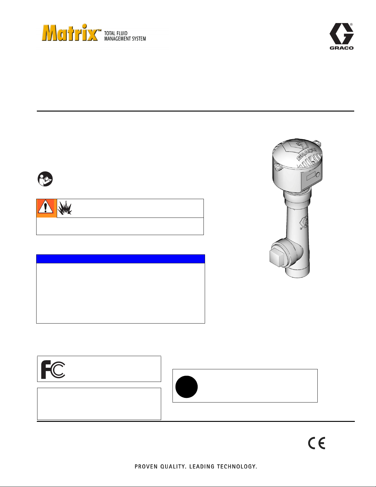
Tank Level Monitor (TLM)
- Monitors tanks levels for oil and anti-freeze mixtures -
Part No. 256285
Use with Graco Matrix 3.0 Software only.
US Patent D484,819
Important Safety Instructions
Read all warnings and instructions in this
manual. Save these instructions.
• Not for use in hazardous locations or in explosive
at
mospheres!
NOTICE
• Do not over tighten tank level monitor into tank bung
er tightening can cause permanent damage and resu
Ov
accurate readings.
in in
• Do not use thread sealant or adhesive! Many of thes
products are chemically incompatib
pla
stic.
• Use the Graco-supplied down tube 15U731 only. Do no
place down tube with any other tube.
re
le with the PC
/ABS
!
lt
e
t
312964C
EN
ti12031a
The Matrix Tank Level Monitor contains an RF device with the following approvals:
FCC ID: TFB-FREESTAR
IC: 5969A-FREESTAR
N14939 - FREESTAR
✓
Industry Canada Statement
The term “IC” before the certification/registration number only signifies that the Industry
Canada technical specifications were met.
ZFMSM-101-1 (CEL) / FS24-100ST (LSR)
Page 2
Warnings
Warnings
The following warnings are for the setup, use, grounding, maintenance, and repair of this equipment. The exclamation point symbol alerts you to a general warning and the hazard symbol refers to procedure-specific risk. Refer back
to these warnings. Additional, product-specific warnings may be found throughout the body of this manual where
applicable.
WARNING
FIRE AND EXPLOSION HAZARD
When flammable fluids are present in the work area, such as gasoline and windshield wiper fluid, be
aware that flammable fumes can ignite or explode. To help prevent fire and explosion:
• Use equipment only in well ventilated area.
• Eliminate all ignition sources, such as cigarettes and portable electric lamps.
• Keep work area free of debris, including rags and spilled or open containers of solvent and gasoline.
• Do not plug or unplug power cords or turn lights on or off when flammable fumes are present.
• Ground all equipment in the work area.
• Use only grounded hoses.
• If there is static sparking or you feel a shock, stop operation immediately. Do not use equipment
until you identify and correct the problem.
• Keep a working fire extinguisher in the work area.
EQUIPMENT MISUSE HAZARD
Misuse can cause death or serious injury.
• Do not operate the unit when fatigued or under the influence of drugs or alcohol.
• Do not exceed the maximum working pressure or temperature rating of the lowest rated system
component. See Technical Data in all equipment manuals.
• Do not leave the work area while equipment is energized or under pressure. Turn off all equipment
and follow the Pressure Relief Procedure in this manual when equipment is not in use.
• Check equipment daily. Repair or replace worn or damaged parts immediately with genuine manufacturer’s replacement parts only.
• Do not alter or modify equipment.
• Use equipment only for its intended purpose. Call your distributor for information.
• Route hoses and cables away from traffic areas, sharp edges, moving parts, and hot surfaces.
• Do not kink or over bend hoses or use hoses to pull equipment.
• Keep children and animals away from work area.
• Comply with all applicable safety regulations.
BATTERY SAFETY
The battery may leak, explode, cause burns, or cause an explosion if mishandled:
• You must use the battery type specified for use with the equipment.
• Sparking can occur when changing batteries. Only replace the battery in a non-hazardous location,
away from flammable fluids or fumes.
• Handle and dispose of battery properly - do not short circuit, charge, force over discharge, disassemble, crush, penetrate, incinerate, or heat the battery to a temperature exceeding 185° F (85° C).
2 312964C
Page 3
Set Up
• Do not install or service this equipment unless you
are trained and qualified. Installing and servicing
this equipment requires access to parts which may
cause fire, explosion, and serious injury if work is
not performed properly. Read warnings, page 2.
Set Up
There are 8 Network ID's and 8 Transceiver ID's possible by changing the position of the dipswitches. The
eight positions are identified as 1, 2, 3, 4, 5, 6, 7 and 8.
See F
IG. 2 and FIG. 3 on pages 4 and 5.
Setting the S1 and S2 Dipswitches
(Unless otherwise indicated, for the following instructions Refer to F
IG. 1 and FIG. 2)
• Do not use the TLM with pressurized tanks.
NOTICE
• Do not over tighten tank level monitor into tank
bung! Over tightening can cause permanent dam-
age and result in inaccurate readings.
• Do not use thread sealant or adhesive. Many of
these products are chemically incompatible with the
PC/ABS plastic.
• Use the Graco-supplied down tube 15U731 only. Do
not replace down tube with any other tube.
Dipswitch Settings
The TLM has two, 4 - position dipswitches labeled S1
and S2. TLM dipswitches must be set to match those of
the transceiver the TLM will be communicating with. The
factory default setting for all TLM’s is (‘1’ ‘1’). The first ‘1’
refers to the Network ID and the second ‘1’ refers to the
Transceiver ID.
• Network ID (S1): The RF identification setting
assigned to a Matrix installation. All components in the system use this same Network ID.
For example, if one dealership is using Network
ID (1), the dealership across the street would
require Network ID (2, 3, 4, 5, 6, 7, or 8) to avoid
RF interference between the two systems.
• Transceiver ID (S2): The RF identification set-
ting assigned to a Matrix Transceiver(s). Matrix
system components are then assigned to the
Transceiver’s ID as desired for RF communication. For example, if a system required two
Transceivers, some components would be
assigned to one Transceiver and other components would be assigned to the second Transceiver.
1
4
3
5
7
2
FIG. 1
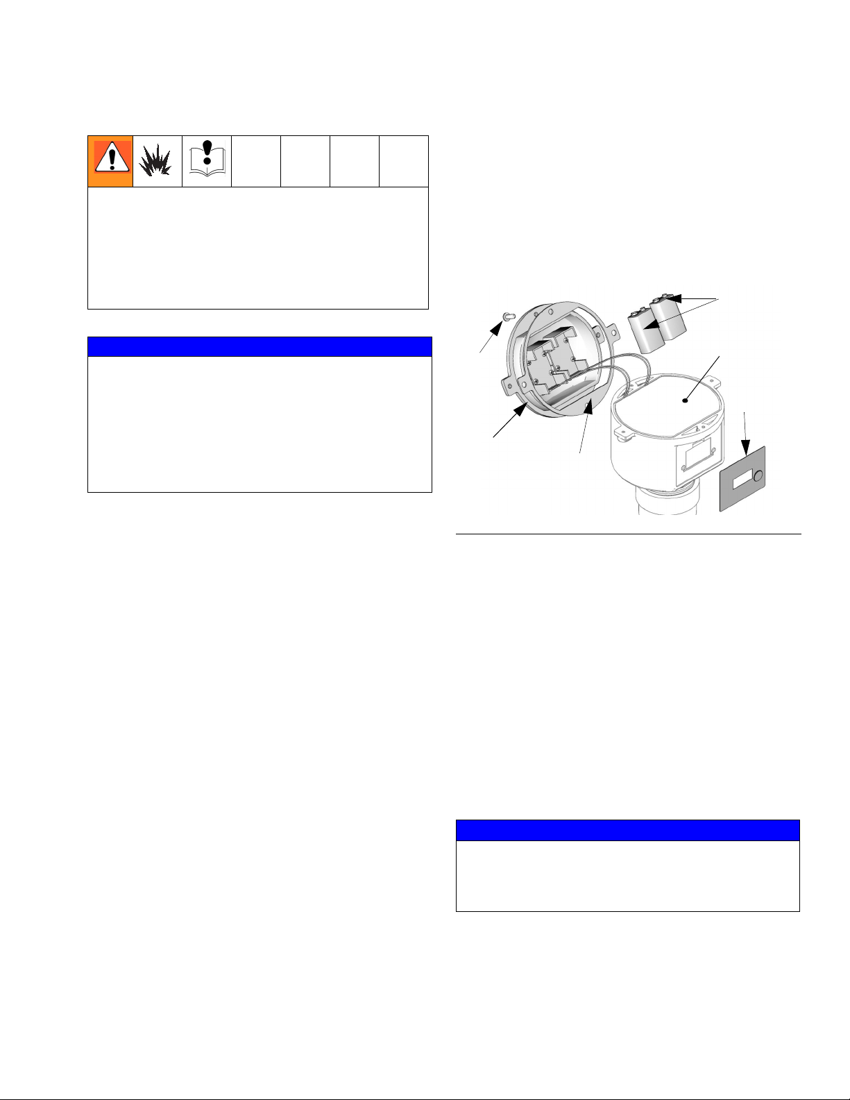
1. Remove the protective plastic over cover (5) on the
TLM display that was used for shipping and discard.
2. Remove the four screws (3) holding the tank monitor
cover (7) in place.
3. Remove the cover (7).
4. Remove the insulating foam (4) to access the circuit
board.
5. If installed, remove batteries (1).
6. Set the S1 and S2 settings to match those of the
transceiver that this TLM will communicate with
(F
IG. 2 and FIG. 3).
NOTICE
Wait at least 30 seconds after the dipswitch settings
are made before installing the batteries. If you do not
wait the 30 seconds, the software will not recognize
the new settings.
312964C 3
Page 4

Set Up
7. Install two, 9-volt alkaline batteries (1). Be sure that
the batteries fully engage the mounting clips by
pushing on the bottom of each battery with your
thumb.
It will take about 30 seconds for the monitor to display information after pressing the Display button
on the initial power-up. This time will decrease
thereafter to a few seconds
8. Replace insulating foam (4).
Make sure the gasket (2) is not damaged and is in
the correct location.
S1 sets NETWORK ID
S2 sets TRANSCEIVER ID
All dipswitches in down
or off position.
on
S2
12
4
3
9. Replace cover (7) and secure it with the four screws
(3).
Make sure the cover screws are tightened securely
(18-22 in-lb) to avoid water leakage into the TLM
electronics. If a torque wrench is not used, verify
there are no gaps under the screw heads and no
gaps under the cover flange. This will ensure
proper compression of the gasket for a water-tight
seal.
F
IG. 2
4
3
2
1
on
S1
All dipswitches
to right or off
position.
ti12007a
4 312964C
Page 5
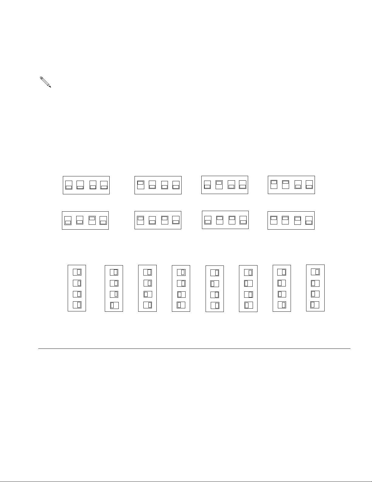
Dipswitch Setting for Network ID and Transceiver ID
See FIG. 3 for dipswitch setting configurations.
b
The batteries must be disconnected and removed before changing dipswitch settings or the TLM will
not be able to communicate with the PC software.
S2 Transceiver ID
Set Up
F
IG. 3
1 - default
on
12
5
on
12
3
1 - default
4
3
2
1
on
S1
S2
S2
3
on
12
7
on
12
4
3
4
3
2
on
S2
4
3
12
4
3
6
on
S2
4
12
4
3
S2
S2
4
on
12
8
on
12
S2
4
3
S2
4
3
S1 Network ID
2
n
o
S1
3
4
3
2
1
n
o
S1
4
4
3
2
1
on
S1
5
4
3
2
1
n
o
S1
6
4
3
2
1
n
o
S1
7
4
3
2
1
n
o
S1
8
4
3
2
1
4
3
2
n
1
o
S1
312964C 5
Page 6

Set Up
Registering the TLM
Graco recommends registering TLM prior to installation.
The TLM operating parameters are controlled by the
Matrix PC Software and setup by the System Administrator. See the Matrix 3 Software instruction manual for
the PC setup instructions.
To register the TLM:
1. Set TLM to correct NETWORK ID and TRANSCEIVER ID (see Dipswitch Settings, page 5).
2. Press and hold the Display button (A, F
IG. 4) until
display (B) says “Register Mode”.
3. Display reads “Registration Complete” when the
TLM is registered with the PC software.
See FIG. 4 for display messages you will see during
Registration Mode.
B
ti12032a
F
IG. 4
A
6 312964C
Page 7

TLM Display
TLM Display
(See FIG. 6, page 8)
TLM ID -
guish it from other TLM’s in the system.
Battery Life - Remaining life of the unit’s batteries. Sys-
tem Administrator on Matrix PC Software determines
when Low Battery Warning message is generated.
Network ID and Transceiver ID - Shows the Network
ID and Transceiver ID TLM is using (also see page 3).
Firmware - Current version of operating software controlling TLM operation.
Fluid Level - Depth of fluid remaining in the tank provided in either inches or centimeters as defined during
setup.
Unique number assigned to the TLM to distin-
Battery life is dependent on the number of readings
taken per day.
Fluid Volume -Volume of fluid remaining in the tank,
based on the tank geometry defined during setup. The
TLM can be programmed to display in either gallons or
liters during programming of the TLM.
Vertical tanks use this capacity figure to calculate
tank volume. Obround and cylindrical tanks use the
tank dimensions to calculate tank volume.
No RF Signal - Displays when the TLM is not receiving
an RF ACK signal from the PC transceiver. If the tank
level monitor is receiving an ACK signal or the signal is
re-established, this screen will not appear.
If the message “No RF Signal” appears, the fluid volume
and battery life data is not transmitted or updated at the
PC. This message may take up to 15 seconds to display.
No PC Signal - Displays when the TLM is not receiving
a response from the Matrix PC software (i.e, PC is off or
software is not installed). If the TLM receives a response
from the PC, this information will not appear.
If the message “NO PC SIGNAL” appears, the fluid volume and battery life data will not be updated at the PC.
This message may take up to 15 seconds to display.
312964C 7
Page 8

TLM Registration Process
TLM Registration Process
Press & Hold
DISPLAY button
TLM ID
Battery
NW ID
TX ID
No Ack received from
Transceiver
Display Reads
No RF Signal
REGISTER
MODE
Ack received from
TLM ID
VERSION
xx.xx.xx
BLANK
PC Responds with
Registration Ack
Message
Transceiver
TLM ID
VERSION
xx.xx.xx
BLANK
PC doesn’t Respond
REGISTER
COMPLETE
Display Reads
No PC Signal
FIG. 5
8 312964C
Page 9

Installation
Installation
NOTICE
• Do not over tighten tank level monitor into tank
bung! Over tightening can cause permanent dam-
age and result in inaccurate readings.
• Do not use thread sealant or adhesive! Many of
these products are chemically incompatible with the
PC/ABS plastic.
• Use the Graco-supplied down tube 15U731 only. Do
not replace down tube with any other tube.
1. Remove the bung fitting and screw in the TLM
hand-tight. DO NOT use a wrench to tighten as this
may damage the TLM. Do not use thread lock adhesive as this may damage the TLM.
2. The TLM must be mounted within 2 degrees from
perpendicular to the surface of the fluid. A level that
measures degrees should be used. Place the level
on the top of the pipe fitting on the tank. If outside
the 2 degree specification, the fitting should be
changed.
Graco recommends that the height of the tank fitting
should not exceed 1/2 in. (1.27 cm). The fitting
height can be up to 2 in. (5.08 cm), provided the fitting is within 2 degrees of the surface of the fluid.
Also, the taller the tank, the more critical the 2
degree specification becomes. See F
IG. 6.
NOTICE
• The TLM will not operate correctly if tilted more than
2° from the surface of the tank liquid.
• The TLM will not read properly if:
TLM must be mounted within 2° from perpendicular to
the surface of the fluid.
2°
2°
FIG. 6
NOTICE
Do not install the TLM in the tank’s fill port. Repeated
removal of the TLM will damage the unit and void the
warranty.
Port (D) is not to be used as a fill hole for oil deliveries.
See F
IG. 7.
The tank’s breather port might be the only available
location for mounting the TLM. The horizontal 2 in. npt
port (D) can be used to accommodate the breather. The
breather should be mounted in an upright position using
a 90° elbow fitting.
Do not use the horizontal port for routing pressure
relief return tubes. This can result in inaccurate
readings.
- Fluid in the tank is agitated (i.e. filling a tank
with oil or anti-freeze). Be sure to take all TLM
readings when the fluid in the tank is calm.
- TLM is mounted next to the tank wall or in a cor-
ner.
- If there is any structural bracing or obstruction
D
between the TLM and the surface of fluid in
tank.
- If the down tube is not the Graco-supplied down
tube.
ti12034a
F
IG. 7
312964C 9
Page 10

Viewing Data
Viewing Data
After a tank is refilled from an oil distributor or a
waste oil tank is emptied by a waste oil service
provider, press the Display button on the TLM to
ensure the TLM will maintain the most current
tank volume status. If button is not pushed, the
TLM will automatically read correctly at the next
scheduled tank reading.
B
A
IG. 8
F
Press and release the Display button (A). Data appears
on display (B); each screen lasting a few seconds before
going on to the next. See F
Tank Level data can be viewed remotely at the PC,
using the Matrix software.
TLM ID
IG. 8.
First Display
03000001
Battery
100%
Nw ID - A
Second Display
Third Display
Tx ID - A
Daylight Saving Time (DST) Change
The PC software automatically changes the PC time
when daylight saving time changes occur (Spring and
Fall).
The first TLM reading will be 1 hour earlier or later
(depending on the Spring or Fall daylight saving
time change), but all subsequent TLM reading will
be accurate.
36‚
Fourth Display
Fluid
100
Gallons
No RF
Signal
NO PC
Signal
F
IG. 9:
10 312964C
Fifth Display
(can program for liters)
Screen display when
no RF ACK signal is
received after 10-12
seconds
Displays when PC
doesn’t respond after
10-12 seconds
Page 11

Troubleshooting
Problem Cause Solution
Brand new monitor’s display is very dim.
Monitor displays “Invalid
Reading”.
Monitor will not register. Transceiver is not powered-up. Verify transceiver is powered-up
Monitor has intermittent
RF communication
Monitor is not reporting
scheduled readings.
Monitor will not take reading when Display button
is pressed.
Unit is shipped with protective coating over display.
The TLM reading is outside of the
programmed size parameters.
Attempt to program while red lights
on transceiver are lit.
Transceiver NET ID and TRANS ID
not set correctly
TLM dipswitches settings do not
match transceiver settings.
Weak or dead batteries. Replace batteries. See Replacing Batteries, page 13.
Microprocessor not completely shut
down before installing new batteries.
USB cable or RS-422 not connected Be sure cable are properly connected between Transceiver
Out of RF range.
RF obstruction.
Weak or dead batteries. Replace batteries. See Replacing Batteries, page 13.
Out of RF range.
RF obstruction.
Two TLMs are programmed to the
same address.
Weak or dead batteries. Replace batteries. See Setting the S1 and S2 Dipswitches,
Microprocessor not completely shut
down before installing new batteries.
Tank Level Monitor was not associated with profile after scheduled
times were entered into software.
Reading is scheduled when pump is
operating.
Clock was changed on PC but the
tank level monitor was not resychronized.
Weak or dead batteries. Replace batteries. See Replacing Batteries, page 13.
Batteries are not correctly seated. Ensure the batteries fully engage the mounting clips by push-
Microprocessor not completely shut
down before installing new batteries.
Monitor display is cracked. Replace monitor display.
PC is not running Turn on PC. In order for TLM readings to be logged, PC must
Remove protective coating.
Verify the programmed parameters and re-program the TLM if
necessary.
Wait until red lights on transceiver go blank before attempting
to register.
Ensure NET ID and TRANS ID are set for appropriate communication cable.
Verify settings with Transceiver (see page. 5 for dipswitch setting instructions).
After you have removed old batteries, wait 30 seconds to
ensure the microprocessor has completely shut down, before
installing new batteries.
and PC
Reposition Transceiver until TLM has good RF communication
or add a transceiver.
Reposition Transceiver until TLM has good RF communication.
Verify that each TLM is correctly programmed to a unique
address.
page 3.
After you have removed old batteries, wait 30 seconds to
ensure the microprocessor has completely shut down, before
installing new batteries.
Reregister Tank Level Monitor and associate Tank Level Monitor with profile ID.
Ensure readings are scheduled at times that the pump is not
operating.
The monitor’s internal clock is synchronized with the PC clock
upon register or reading. Manipulating the scheduled reporting
time by changing the PC clock will cause a false indication that
the monitor is not reporting at the scheduled reporting times.
ing on the bottom of each battery with your thumbs.
After you have removed old batteries, wait 30 seconds to
ensure the microprocessor has completely shut down, before
installing new batteries.
be running.
Troubleshooting
312964C 11
Page 12

Troubleshooting
Monitor readings are
inaccurate.
Problem Cause Solution
Tank geometry incorrectly defined. See Tank Level Monitor Software Guide or PC Software Guide
for details.
Tank Level Monitor has not been
updated with latest adjustments
made within The profile ID on the
PC.
Two TLMs are programmed to the
same address.
Fluid surface is moving while reading
is being taken.
Pipe adapters installed in the tank
bung.
Tank Level Monitor is not perpendicular to top of fluid.
Inside tank obstruction. Install in different tank bung to avoid tank obstruction.
Manually push DISPLAY button on TLM
Verify that each TLM is correctly programmed to a unique
address.
Ensure pump is not operating and that nothing is disturbing the
surface of the fluid during readings.
Ensure there are no adapters installed in the tank bung.
Level tank so that it is perpendicular to top of the fluid and/or
realign Tank Level Monitor.
12 312964C
Page 13

Service
Service
Once the Tank Level Monitor has been installed, no additional maintenance or service is necessary, with the exception of replacing batteries.
Replacing Batteries
Always replace both batteries with two new 9-volt alkaline batteries whenever you change batteries in the TLM.
Sparking can occur when changing batteries. Only
replace the battery in a non-hazardous location,
away from flammable fluids or fumes.
1. Remove the four cover screws (3) and cover (7).
2. Disconnect and remove both batteries (1) from TLM
and discard batteries in approved battery disposal
container.
3. Replace discarded batteries with two new batteries.
Be sure the batteries fully engage the mounting
clips by pushing on the bottom of each battery with
your thumb.
4. Replace the cover (7) and screws (3). Tighten the
four cover screws.
• Make sure the cover screws are tightened
securely (18-22 in-lb) to avoid water leakage
into the TLM electronics. If a torque wrench is
not used, verify there are no gaps under the
screw heads and no gaps under the cover
flange. This will ensure proper compression of
the gasket for a water-tight seal.
• After changing batteries it is not necessary to
reprogram the TLM. However, the Display button should be pressed to synchronize the
TLM’s internal clock with the PC clock. If not
done, the TLM will not report at the correct
scheduled times.
312964C 13
Page 14

Parts
Parts
1
2
4
3
8
1
6
7
2
5
9
10
1
Remove protective cover used for shipping before
programming.
2
Do not remove. This is required to maintain intrinsic safety approval.
Ref.
Part No. Description Qty
No.
1 BATTERY, 9 volt (purchased locally) 2
2 126752 GASKET, sensor, ultrasonic 1
3 117467 SCREW, self tapping, HI-LO, #10-16 x 9/16 4
4 117743 FOAM, insulator 1
5 117259 ENCLOSURE 1
6 15T814 LABEL, overlay 1
7 15A962 COVER 1
8 117469 HOLDER, battery 2
9 15U731 DOWN TUBE 1
10 119391 PLUG
ti12033a
14 312964C
Page 15

Technical Data
Technical Data
Ultrasonic Tank Depth Measurement range 0 - 30 ft. (0 - 9 m) Not for use in pressurized tanks.
Fluid Level Measurement Accuracy +/- 0.5%
Mounting Standard 2 in. (npt) bung.
Height above tank for TLM and tube mounting
TLM Mounting Tube and Tank Vent Graco recommends venting the tank separately from the TLM. If not
Weight (with batteries installed) 2.34lb. (1.06 g)
RF Communication 2.4 GHz
Operating Temperature Range -22° F to 185° F (- 30° C to 85° C) Note: Display will not function
Storage Temperature Range -40°F to 185°F (-40°C to 85°C)
Batteries Two 9V alkaline
Battery Life 1.5 years
Enclosure IP65
RF Communication 2.4 GHz
Obstructed RF Communication Range
(based on building construction and RF environment)
Tank Geometry Vertical walled tanks, cylindrical tanks, and obround tanks.
15 in. (30.48 cm).
possible, the TLM mounting and vent function can be combined if
required for tanks with one hole in tank. Be sure TLM is not mounted
close to tank edges or corner.
below 32°F (0°C).
250-300 ft (76.2 - 91.0 m)
•Vertical Tanks
Maximum Volume 999,999 gallons or liters
Maximum Height 30 ft. (360 in.)
•Cylindrical Tanks
Maximum Volume 999,999 gallons or liters
Maximum Diameter 30 ft. (360 in.)
Maximum Length 30 ft. (360 in.)
•Obround Tanks
Maximum Volume 999,999 gallons or liters
Maximum Height 30 ft. (360 in.)
Maximum Width 30 ft. (360 in.)
Maximum Length 30 ft. (360 in.)
Approvals FCC, Industry Canada (IC), C-Tick, CE
NOTE: FCC, C-Tick and IC approvals are for the RF device contained in the Matrix Tank Level Monitor (TLM).
312964C 15
Page 16

Dimensions
Dimensions
A 9.1 in (231 mm)
B 4.9 in. (124 mm)
B
1-1/2 in. npt
2 in. npt
A
ti12031a
16 312964C
Page 17

Tank Geometry
Vertical Tank:
• Maximum Volume = 999, 999 gallons or liters.
• Tank walls must be uniformly vertical from empty level to full
Maximum Height
30 ft. (360 in.)
Tank Geometry
F
IG. 10
ti12693a
312964C 17
Page 18

Tank Geometry
Cylindrical Tank:
• Maximum Volume = 999, 999 gallons or liters.
• Tank end walls must be flat; they cannot be any other shape, including belled.
Maximum Height
30 ft. (360 in)
F
IG. 11
Maximum Length
30 ft. (360 in)
ti12695a
18 312964C
Page 19

Obround Tank:
• Maximum Volume = 999, 999 gallons or liters.
• Tank end walls must be flat; they cannot be any other shape including belled.
Maximum Height
30 ft. (360 in)
Tank Geometry
Maximum Width
30 ft. (360 in.)
F
IG. 12
Maximum Length
30 ft. (360 in)
ti12694a
312964C 19
Page 20

Graco Extended Tank Level Monitor Warranty
Graco warrants all equipment manufactured by Graco and bearing its name to be free from defects in material and workmanship
on the date of sale to the original purchaser for use. With the exception of any special, extended, or limited warranty published by
Graco, Graco will, for a period of twenty four months from the date of sale, repair or replace any part of the equipment determined
by Graco to be defective. This warranty applies only when the equipment is installed, operated and maintained in accordance with
Graco's written recommendations.
This warranty does not cover, and Graco shall not be liable for general wear and tear, or any malfunction, damage or wear caused
by faulty installation, misapplication, abrasion, corrosion, inadequate or improper maintenance, negligence, accident, tampering,
or substitution of non-Graco component parts. Nor shall Graco be liable for malfunction, damage or wear caused by the
incompatibility of Graco equipment with structures, accessories, equipment or materials not supplied by Graco, or the improper
design, manufacture, installation, operation or maintenance of structures, accessories, equipment or materials not supplied by
Graco.
This warranty is conditioned upon the prepaid return of the equipment claimed to be defective to an authorized Graco distributor
for verification of the claimed defect. If the claimed defect is verified, Graco will repair or replace free of charge any defective parts.
The equipment will be returned to the original purchaser transportation prepaid. If inspection of the equipment does not disclose
any defect in material or workmanship, repairs will be made at a reasonable charge, which charges may include the costs of parts,
labor, and transportation.
THIS WARRANTY IS EXCLUSIVE, AND IS IN LIEU OF ANY OTHER WARRANTIES, EXPRESS OR IMPLIED, INCLUDING BUT
NOT LIMITED TO WARRANTY OF MERCHANTABILITY OR WARRANTY OF FITNESS FOR A PARTICULAR PURPOSE.
Graco's sole obligation and buyer's sole remedy for any breach of warranty shall be as set forth above. The buyer agrees that no
other remedy (including, but not limited to, incidental or consequential damages for lost profits, lost sales, injury to person or
property, or any other incidental or consequential loss) shall be available. Any action for breach of warranty must be brought within
two (2) years of the date of sale Graco makes no warranty, and disclaims all implied warranties of merchantability and fitness for a
particular purpose in connection with accessories, equipment, materials or components sold but not manufactured by Graco.
These items sold, but not manufactured by Graco (such as electric motors, switches, hose, etc.), are subject to the warranty, if any,
of their manufacturer. Graco will provide purchaser with reasonable assistance in making any claim for breach of these warranties.
In no event will Graco be liable for indirect, incidental, special or consequential damages resulting from Graco supplying
equipment hereunder, or the furnishing, performance, or use of any products or other goods sold hereto, whether due to a breach
of contract, breach of warranty, the negligence of Graco, or otherwise.
FOR GRACO CANADA CUSTOMERS
The parties acknowledge that they have required that the present document, as well as all documents, notices and legal
proceedings entered into, given or instituted pursuant hereto or relating directly or indirectly hereto, be drawn up in English. Les
parties reconnaissent avoir convenu que la rédaction du présente document sera en Anglais, ainsi que tous documents, avis et
procédures judiciaires exécutés, donnés ou intentés à la suite de ou en rapport, directement ou indirectement, avec les
procedures concernées.
TO PLACE AN ORDER, contact your Graco distributor or call to identify the nearest distributor.
Phone: 612-623-6928 or Toll Free: 1-800-533-9655, Fax: 612-378-3590
All written and visual data contained in this document reflects the latest product information available at the time of publication.
Graco reserves the right to make changes at any time without notice.
For patent information, see www.graco.com/patents.
Original Instructions. This manual contains English. MM 312964
Graco Headquarters: Minneapolis
International Offices: Belgium, China, Japan, Korea
GRACO INC. P.O. BOX 1441 MINNEAPOLIS, MN 55440-1441
Copyright 2008, Graco Inc. is registered to I.S. EN ISO 9001
www.graco.com
Revised September 2012
 Loading...