

Page 1
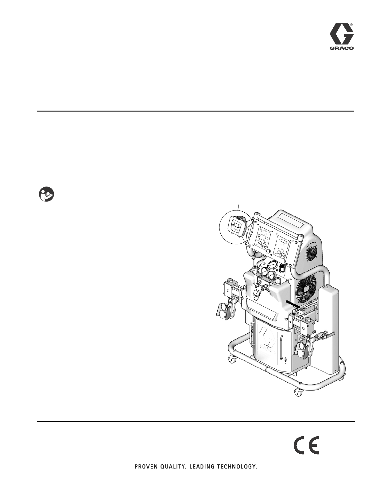
Installation - Operation
Shot Controller
For use with non-flammable polyurethane foams. For professional use only.
Not approved for use in European explosive atmosphere locations.
2000 psi (13.8 MPa, 138 bar) Maximum Working Pressure
312878J
ENG
Important Safety Instructions
Read all warnings and instructions in this
manual and the Hydraulic Reactor
Operation manual. Save all instructions.
See page 3 for model information.
Proportioner shown includes Shot Controller,
™
proportioner also available without Shot Controller
ti11756a
Page 2
Related Manuals
Contents
Related Manuals . . . . . . . . . . . . . . . . . . . . . . . . . . . 2
Models . . . . . . . . . . . . . . . . . . . . . . . . . . . . . . . . . . . 3
Warnings . . . . . . . . . . . . . . . . . . . . . . . . . . . . . . . . . 4
Isocyanate Hazard . . . . . . . . . . . . . . . . . . . . . . . . . 6
Material Self-ignition . . . . . . . . . . . . . . . . . . . . . . . 6
Moisture Sensitivity of Isocyanates . . . . . . . . . . . . 6
Keep Components A and B Separate . . . . . . . . . . 6
Foam Resins with 245 fa Blowing Agents . . . . . . . 6
Changing Materials . . . . . . . . . . . . . . . . . . . . . . . . . 6
Component Identification . . . . . . . . . . . . . . . . . . . . 7
IPH System . . . . . . . . . . . . . . . . . . . . . . . . . . . . . 7
Human Machine Interface (HMI) . . . . . . . . . . . . 8
Icons . . . . . . . . . . . . . . . . . . . . . . . . . . . . . . . . . 9
Run Screen . . . . . . . . . . . . . . . . . . . . . . . . . . . 11
Conversion Kit Installation . . . . . . . . . . . . . . . . . . 13
Disable Motor Standby Operation . . . . . . . . . . . 17
Simplified Schematic, Shot Controller Wiring . . 18
Simplified Schematic, Shot Controller Electrical 19
Simplified Schematic, Alternate Gun Connection 20
Setup . . . . . . . . . . . . . . . . . . . . . . . . . . . . . . . . . . . . 21
Hydraulic Proportioner Setup . . . . . . . . . . . . . . 21
Controller Setup . . . . . . . . . . . . . . . . . . . . . . . . 21
Password Protection . . . . . . . . . . . . . . . . . . . . . 23
Learn Mode . . . . . . . . . . . . . . . . . . . . . . . . . . . . 24
Piston Size . . . . . . . . . . . . . . . . . . . . . . . . . . . . 25
Optional External Machine Control . . . . . . . . . . 26
Operation . . . . . . . . . . . . . . . . . . . . . . . . . . . . . . . . 29
Startup . . . . . . . . . . . . . . . . . . . . . . . . . . . . . . . 29
Change Operating Mode . . . . . . . . . . . . . . . . . . 29
Change Shot Number . . . . . . . . . . . . . . . . . . . . 29
Change Shot Volume/Weight . . . . . . . . . . . . . . 29
Sequence Mode Options . . . . . . . . . . . . . . . . . 30
Dispense Material . . . . . . . . . . . . . . . . . . . . . . 31
Maintenance Mode . . . . . . . . . . . . . . . . . . . . . 31
Demo Mode . . . . . . . . . . . . . . . . . . . . . . . . . . . 31
Hibernate Mode . . . . . . . . . . . . . . . . . . . . . . . . 31
Shutdown . . . . . . . . . . . . . . . . . . . . . . . . . . . . . 31
Pressure Relief Procedure . . . . . . . . . . . . . . . . . . 32
Troubleshooting . . . . . . . . . . . . . . . . . . . . . . . . . . 33
Error Codes . . . . . . . . . . . . . . . . . . . . . . . . . . . 33
Parts . . . . . . . . . . . . . . . . . . . . . . . . . . . . . . . . . . . . 34
Hydraulic Proportioner . . . . . . . . . . . . . . . . . . . . 34
Conversion Kit 24A024 . . . . . . . . . . . . . . . . . . . 34
Technical Data . . . . . . . . . . . . . . . . . . . . . . . . . . . . 36
Performance Charts . . . . . . . . . . . . . . . . . . . . . . . . 37
Graco Ohio Standard Warranty . . . . . . . . . . . . . . 38
Graco Ohio Information . . . . . . . . . . . . . . . . . . . . . 38
Related Manuals
These manuals can be found at www.graco.com.
Reactor Hydraulic Proportioner
Part Description
312062
312063
Reactor Electric Diagrams
Part Description
312064
AR Pour Gun
Part Description
312888 AR Pour Gun, Operation-Parts Manual
Proportioning Pump
312068 Proportioning Pump Repair-Parts Manual
Reactor Hydraulic Proportioner, Operation
Manual
Reactor Hydraulic Proportioner,
Repair-Parts Manual
Reactor Hydraulic Proportioner, Electrical
Diagrams
2 312878J
Page 3
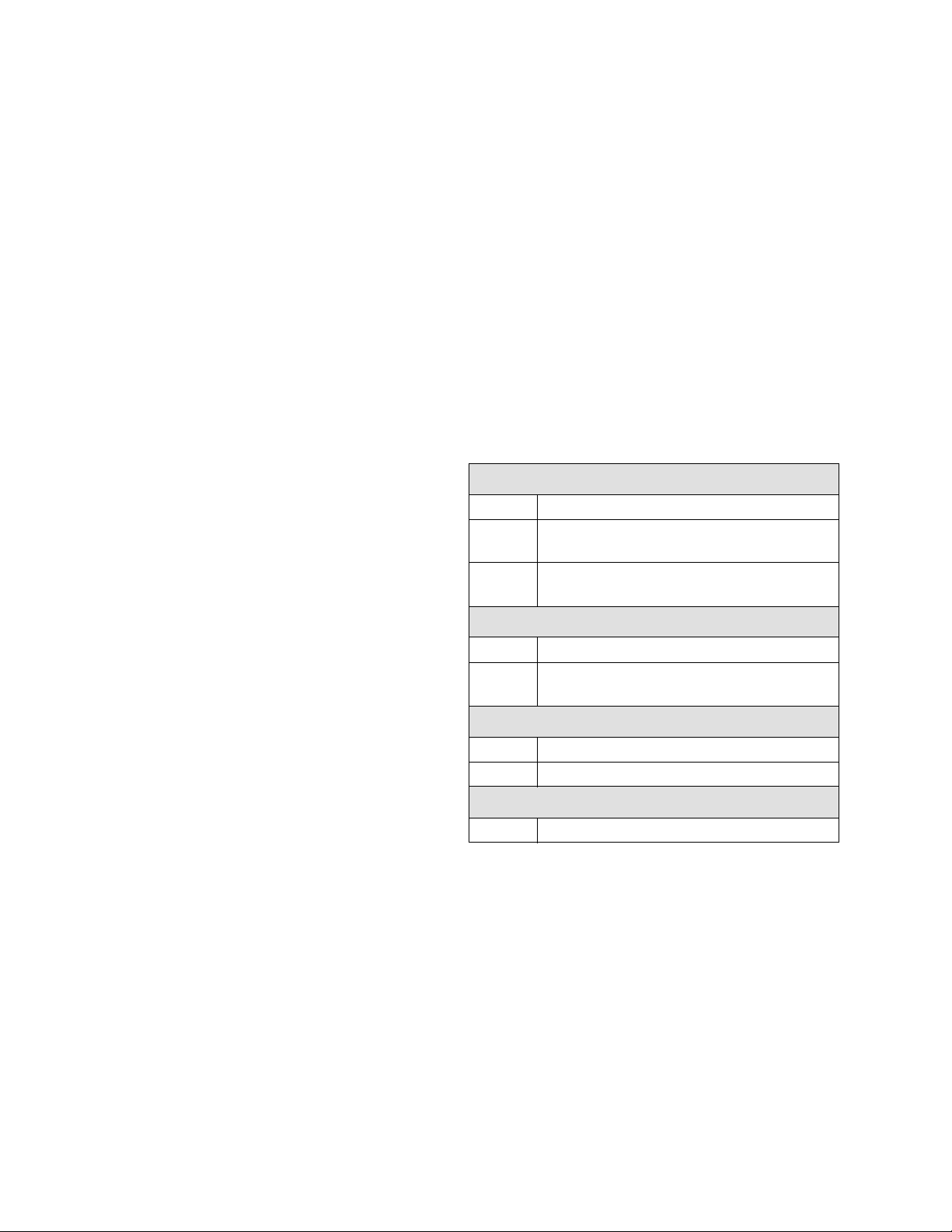
Models
Models
IPH-25 SERIES
Max Flow
Full Load
Part,
Series
255814, B 69 230V (1) 15960 8000 22 (10) 0.063 (0.24) 1.91:1 2000 (13.8, 138)
255815, B 46 230V (3) 15960 8000 22 (10) 0.063 (0.24) 1.91:1 2000 (13.8, 138)
255816, B 35 400V (3) 15960 8000 22 (10) 0.063 (0.24) 1.91:1 2000 (13.8, 138)
255819, A 100 230V (1) 23260 15300 22 (10) 0.063 (0.24) 1.91:1 2000 (13.8, 138)
255820, A 89 230V (1) 23260 15300 22 (10) 0.063 (0.24) 1.91:1 2000 (13.8, 138)
255824, B 69 230V (1) 15960 8000 22 (10) 0.063 (0.24) 1.91:1 2000 (13.8, 138)
255825, B 46 230V (3) 15960 8000 22 (10) 0.063 (0.24) 1.91:1 2000 (13.8, 138)
255826, B 35 400V (3) 15960 8000 22 (10) 0.063 (0.24) 1.91:1 2000 (13.8, 138)
Peak Amps*
Per Phase
Volt ag e
(phase)
System
Watts
Primary
Heater
Watts
Rate◆
lb/min
(kg/min)
IPH-40 SERIES
Max Flow
Full Load
Part,
Series
255811, B 100 230V (1) 23100 12000 50 (23) 0.076 (0.29) 1.64:1 2000 (13.8, 138)
255812, B 71 230V (3) 26600 15300 50 (23) 0.076 (0.29) 1.64:1 2000 (13.8, 138)
255813, B 41 400V (3) 26600 15300 50 (23) 0.076 (0.29) 1.64:1 2000 (13.8, 138)
255821, B 100 230V (1) 23100 12000 50 (23) 0.076 (0.29) 1.64:1 2000 (13.8, 138)
255822, B 71 230V (3) 26600 15300 50 (23) 0.076 (0.29) 1.64:1 2000 (13.8, 138)
255823, B 41 400V (3) 26600 15300 50 (23) 0.076 (0.29) 1.64:1 2000 (13.8, 138)
Peak Amps*
Per Phase
Voltage
(phase)
System
Watts
Primary
Heater
Watts
Rate◆
lb/min
(kg/min)
Approximate
Output per
Cycle (A+B)
gal. (liter)
Approximate
Output per
Cycle (A+B)
gal. (liter)
Hydraulic
Pressure
Ratio
Hydraulic
Pressure
Ratio
Maximum Fluid
Working
Pressure
psi (MPa, bar)
Maximum Fluid
Working
Pressure
psi (MPa, bar)
CONVERSION KIT
Part, Series Description
24A024, A Conversion kit for existing H-25 and H-40 hydraulic proportioners
* Full load amps with all devices operating at maximum capabilities. Fuse requirements at various flow rates and mix
chamber sizes may be less.
◆ Maximum flow rate given for 60 Hz operation. For 50 Hz operation, maximum flow rate is 5/6 of 60 Hz maximum
flow.
312878J 3
Page 4
Warnings
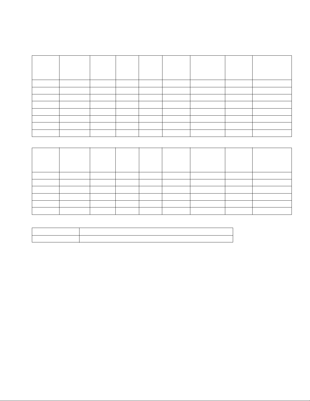
Warnings
The following warnings are for the setup, use, grounding, maintenance, and repair of this equipment. The exclamation point symbol alerts you to a general warning and the hazard symbol refers to procedure-specific risk. Refer back
to these warnings. Additional, product-specific warnings may be found throughout the body of this manual where
applicable.
WARNING
TOXIC FLUID OR FUMES HAZARD
Toxic fluids or fumes can cause serious injury or death if splashed in the eyes or on skin, inhaled, or
swallowed.
• Read MSDS’s to know the specific hazards of the fluids you are using.
• Store hazardous fluid in approved containers, and dispose of it according to applicable guidelines.
• Always wear impervious gloves when spraying or cleaning equipment.
PERSONAL PROTECTIVE EQUIPMENT
You must wear appropriate protective equipment when operating, servicing, or when in the operating
area of the equipment to help protect you from serious injury, including eye injury, inhalation of toxic
fumes, burns, and hearing loss. This equipment includes but is not limited to:
• Protective eyewear
• Clothing and respirator as recommended by the fluid and solvent manufacturer
• Gloves
• Hearing protection
SKIN INJECTION HAZARD
High-pressure fluid from dispense valve, hose leaks, or ruptured components will pierce skin. This may
look like just a cut, but it is a serious injury that can result in amputation. Get immediate surgical
treatment.
• Do not point dispense valve at anyone or at any part of the body.
• Do not put your hand over the end of the dispense nozzle.
• Do not stop or deflect leaks with your hand, body, glove, or rag.
• Follow Pressure Relief Procedure in this manual, when you stop spraying and before cleaning,
checking, or servicing equipment.
• Tighten all fluid connections before operating the equipment.
• Check hoses, tubes and couplings daily. Replace worn or damaged parts immediately.
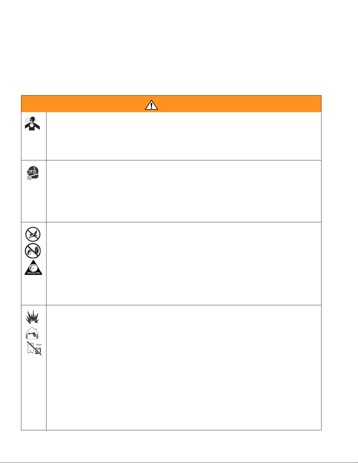
FIRE AND EXPLOSION HAZARD
Flammable fumes, such as solvent and paint fumes, in work area can ignite or explode. To help prevent
fire and explosion:
• Use and clean equipment only in well ventilated area.
• Eliminate all ignition sources; such as pilot lights, cigarettes, portable electric lamps, and plastic drop
cloths (potential static arc).
• Keep work area free of debris, including solvent, rags and gasoline.
• Do not plug or unplug power cords or turn lights on or off when flammable fumes are present.
• Ground equipment, personnel, object being sprayed, and conductive objects in work area. See
Grounding instructions.
• Use only Graco grounded hoses.
• Check gun resistance daily.
• If there is static sparking or you feel a shock, stop operation immediately. Do not use equipment
until you identify and correct the problem.
• Do not flush with gun electrostatics on. Do not turn on electrostatics until all solvent is removed from
system.
• Keep a working fire extinguisher in the work area.
4 312878J
Page 5
Warnings
WARNING
ELECTRIC SHOCK HAZARD
Improper grounding, setup, or usage of the system can cause electric shock.
• Turn off and disconnect power at main switch before disconnecting any cables and before servicing
equipment.
• Connect only to grounded power source.
• All electrical wiring must be done by a qualified electrician and comply with all local codes and
regulations.
PRESSURIZED ALUMINUM PARTS HAZARD
Do not use 1,1,1-trichloroethane, methylene chloride, other halogenated hydrocarbon solvents or fluids
containing such solvents in pressurized aluminum equipment. Such use can cause serious chemical
reaction and equipment rupture, and result in death, serious injury, and property damage.
EQUIPMENT MISUSE HAZARD
Misuse can cause death or serious injury.
• Do not operate the unit when fatigued or under the influence of drugs or alcohol.
• Do not exceed the maximum working pressure or temperature rating of the lowest rated
system component. See Technical Data in all equipment manuals.
• Use fluids and solvents that are compatible with equipment wetted parts. See Technical
Data in all equipment manuals. Read fluid and solvent manufacturer’s warnings. For com-
plete information about your material, request MSDS forms from distributor or retailer.
• Check equipment daily. Repair or replace worn or damaged parts immediately with genuine
manufacturer’s replacement parts only.
• Do not alter or modify equipment.
• Use equipment only for its intended purpose. Call your distributor for information.
• Route hoses and cables away from traffic areas, sharp edges, moving parts, and hot sur-
faces.
• Do not kink or over bend hoses or use hoses to pull equipment.
• Keep children and animals away from work area.
• Comply with all applicable safety regulations.
MOVING PARTS HAZARD
Moving parts can pinch or amputate fingers and other body parts.
• Keep clear of moving parts.
• Do not operate equipment with protective guards or covers removed.
• Pressurized equipment can start without warning. Before checking, moving, or servicing equipment,
follow the Pressure Relief Procedure in this manual. Disconnect power or air supply.
BURN HAZARD
Equipment surfaces and fluid that’s heated can become very hot during operation. To avoid severe
burns, do not touch hot fluid or equipment. Wait until equipment/fluid has cooled completely.
312878J 5
Page 6
Isocyanate Hazard
Isocyanate Hazard
Spraying materials containing isocyanates creates
potentially harmful mists, vapors, and atomized particulates.
Read material manufacturer’s warnings and material
MSDS to know specific hazards and precautions
related to isocyanates.
Prevent inhalation of isocyanate mists, vapors, and
atomized particulates by providing sufficient ventilation in the work area. If sufficient ventilation is not
available, a supplied-air respirator is required for
everyone in the work area.
To prevent contact with isocyanates, appropriate personal protective equipment, including chemically
impermeable gloves, boots, aprons, and goggles, is
also required for everyone in the work area.
Material Self-ignition
• Keep the ISO lube pump reservoir (if installed) filled
with Graco Throat Seal Liquid (TSL), Part 206995.
The lubricant creates a barrier between the ISO and
the atmosphere.
• Use moisture-proof hoses specifically designed for
ISO, such as those supplied with your system.
• Never use reclaimed solvents, which may contain
moisture. Always keep solvent containers closed
when not in use.
• Never use solvent on one side if it has been contaminated from the other side.
• Always lubricate threaded parts with ISO pump oil
or grease when reassembling.
Keep Components A and B Separate
CAUTION
To prevent cross-contamination of the equipment’s
wetted parts, never interchange component A (isocyanate) and component B (resin) parts.
Some materials may become self-igniting if applied
too thickly. Read material manufacturer’s warnings
and material MSDS.
Moisture Sensitivity of Isocyanates
Isocyanates (ISO) are catalysts used in two component
foam and polyurea coatings. ISO will react with moisture
(such as humidity) to form small, hard, abrasive crystals,
which become suspended in the fluid. Eventually a film
will form on the surface and the ISO will begin to gel,
increasing in viscosity. If used, this partially cured ISO
will reduce performance and the life of all wetted parts.
The amount of film formation and rate of crystallization varies depending on the blend of ISO, the
humidity, and the temperature.
To prevent exposing ISO to moisture:
• Always use a sealed container with a desiccant
dryer in the vent, or a nitrogen atmosphere. Never
store ISO in an open container.
Foam Resins with 245 fa Blowing Agents
New foam blowing agents will froth at temperatures
above 90°F (33°C) when not under pressure, especially
if agitated. To reduce frothing, minimize preheating in a
circulation system.
Changing Materials
• When changing materials, flush the equipment multiple times to ensure it is thoroughly clean.
• Always clean the fluid inlet strainers after flushing.
• Check with your material manufacturer for chemical
compatibility.
• Most materials use ISO on the A side, but some use
ISO on the B side.
• Epoxies often have amines on the B (hardener)
side. Polyureas often have amines on the B (resin)
side.
6 312878J
Page 7
Component Identification
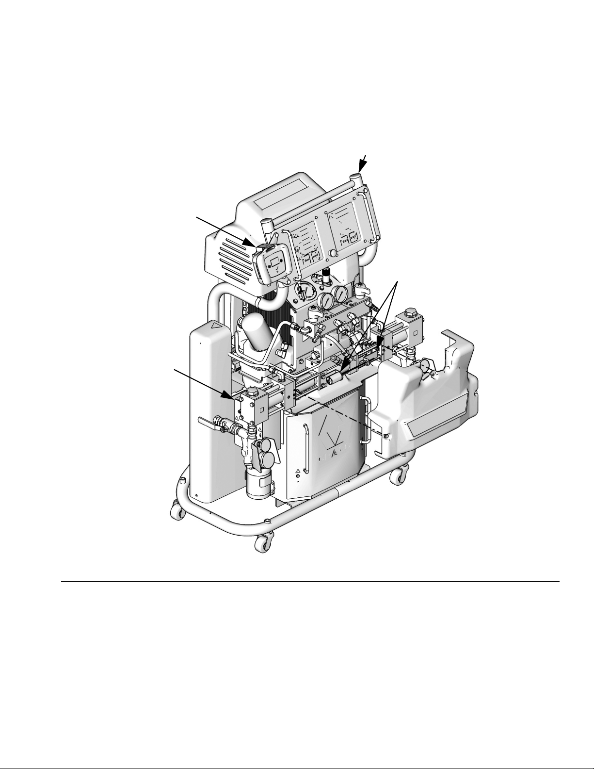
IPH System
B
Component Identification
A
D
C
Model 255811 shown
FIG. 1: IPH System with Front Cover Removed
Key:
A Hydraulic Proportioner
B Shot Controller, HMI, and Bracket
C Electrical Enclosure
D Linear Sensor Assembly
ti11820a
312878J 7
Page 8
Component Identification
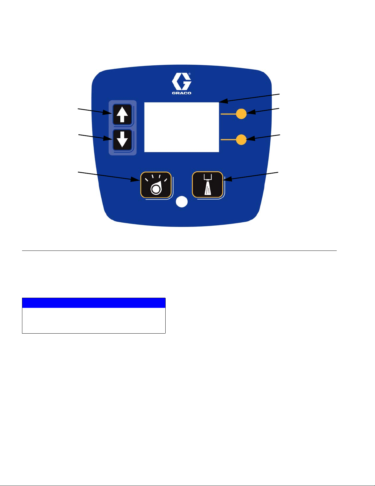
Human Machine Interface (HMI)
AG
AA
AB
AC
F
IG. 2
Key:
AA Up arrow key
AB Down arrow key
AC Mode select button
AD Top soft key
AD
AE
AF
AE Bottom soft key
AF Initiate shot button
AG LCD screen
NOTICE
To prevent damage to soft key buttons, do not press
the buttons with sharp objects such as pens, plastic
cards, or fingernails.
Initiate Shot button
Pressing this button will start a shot for either the
selected shot number, the next shot number in the
selected sequence, or when in manual mode will dis-
Mode Select button
Pressing this button will allow selection of an operating
mode. The available choices will always include Shot,
“Sh,” and Manual, “Mn”.
pense until the user releases the button.
If one or more sequences have been programmed, the
This button is initially set as disabled and can be
enabled or disabled from setup screen #7. See Setup
Sequence modes available will show up as the name of
each sequence (“Sq-A,” “Sq-B,” etc.).
Screen #7: Enable/Disable Run Screen Shot Editing
or “Initiate Shot” button on page 23.
8 312878J
Page 9
Icons
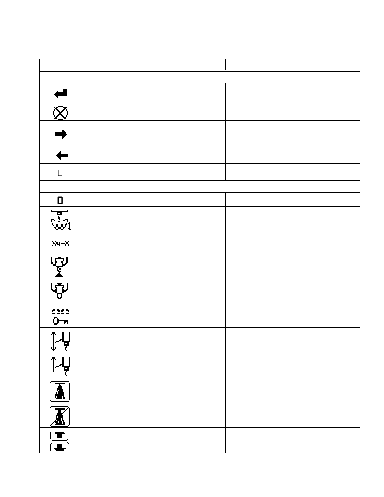
Icon Function Shown on Screen(s)
General Icons
Confirm changes • All
Exit without saving changes • All
• Setup screen #1
Next
Previous
Learn Mode Active Indicator (shown in lower-left
corner)
Setup Icons - see Controller Setup section on page 21
Reset Piston Counter to Zero • Setup screen #1
• Setup screen #3
• Run screen when Learn Mode is enabled
• Setup screen #1
• Run screen when Learn Mode is enabled
• Run screen when Learn Mode is enabled
Component Identification
Define Shot Amount • Setup screen #2
Define Sequence Modes • Setup screen #3
Open Gun Dispense Valve • Setup screen #4
Close Gun Dispense Valve • Setup screen #4
Change Password • Setup screen #5
Enable “Tap” mode • Setup screen #6
Enable “Hold” mode • Setup screen #6
Enable “Initiate Shot” button on HMI • Setup screen #7
Disable “Initiate Shot” button on HMI • Setup screen #7
Enable Run Screen Shot Editing • Setup screen #7
312878J 9
Page 10
Component Identification
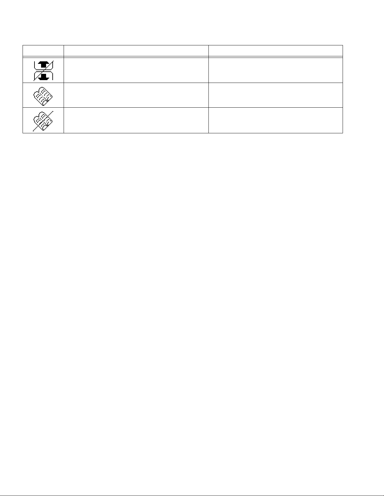
Icon Function Shown on Screen(s)
Disable Run Screen Shot Editing • Setup screen #7
Enter Learn Mode • Setup screen #8
Exit Learn Mode • Setup screen #8
10 312878J
Page 11
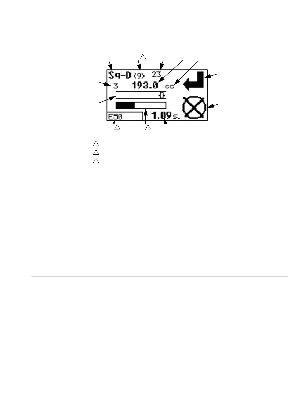
Run Screen
Component Identification
BA
BB
3
BC
BD
BE
BF
BM
BL
BK
1
1
When no errors are active, “E” will be displayed.
2
Shown only during shot dispensing in Shot or Sequence mode
3
Displayed only in Sequence mode
BJ
2
BH
BG
Key:
BA Current operating mode
BB nth shot in sequence
BC Number of shots executed for selected shot number
BD Quantity of selected shot (Shot or Sequence modes) or previous shot
(Manual mode)
BE Quantity unit of measure (cubic centimeters or grams)
BF Top soft key icon
BG Bottom soft key icon
BH Duration of selected shot (Shot or Sequence modes) or previous shot
(Manual mode)
BJ Progress bar for current shot
BK Error status
BL Piston position
BM Shot number currently selected
F
IG. 3: Run Screen
Run Screen Variables
Available operating modes vary by setup but will include
“Sh” for predefined shot mode and “Mn” for manual shot
mode. If sequences have been defined, operating mode
options will include “Sq-A”, “Sq-B”, etc. to select any of
the defined sequences. See Change Operating Mode
on page 29.
Shot quantity can be displayed either in cubic centimeters or grams depending on whether specific gravity is
entered. See Setup Screen #6: Quantity Units and
Gun Configuration on page 22.
312878J 11
The top and bottom soft key icons indicate the function
of the respective soft key. See Icons section on page 9
for icon descriptions.
Page 12
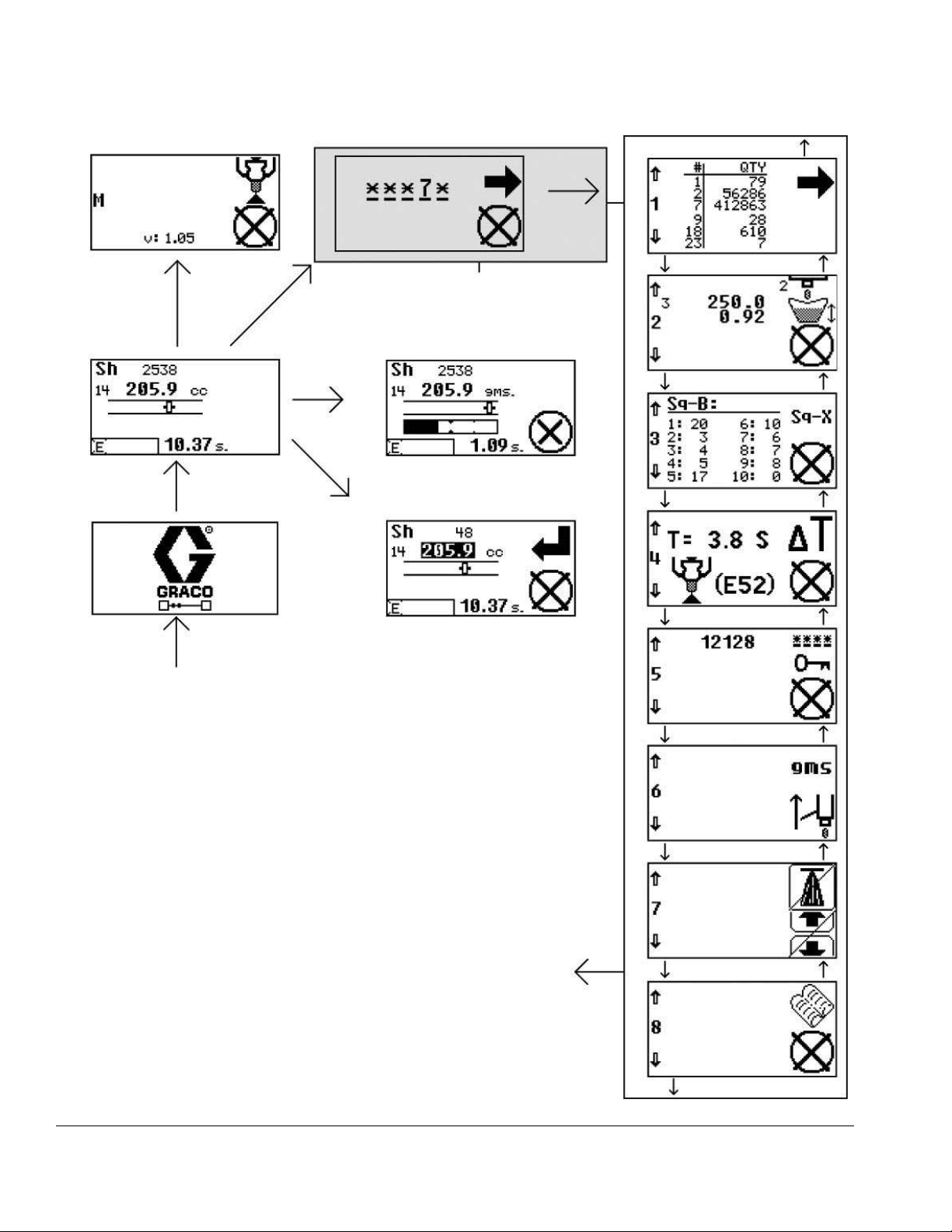
Component Identification
Maintenance Mode
Press and hold bottom
soft key for 2 sec
Idle Run Screen
After 15 sec
for 3 se
key
ft
Press and hold top
so
Initiate shot
Pr
e
ar
ss a
r
ow ke
n
d h
ys
o
for 3 s
c
ld b
e
Press up arrow key to
access Setup Screen 8
Enter and confirm
correct password
Password Entry
This screen is skipped
when password is disabled
Dispensing
Run Screen
o
th
c
Setup Screen 1
Press down
arrow key
Setup Screen 2
Press down
arrow key
Setup Screen 3
Press down
arrow key
Press up
arrow key
Press up
arrow key
Press up
arrow key
Splash Screen
Tur n on HM I
START
Run Screen
Shot Editing
Exit setup screens and return to Idle Run Screen by
pressing and holding both soft keys for 3 sec
Setup Screen 4
Press down
arrow key
Setup Screen 5
Press down
arrow key
Setup Screen 6
Press down
arrow key
Setup Screen 7
Press down
arrow key
Press up
arrow key
Press up
arrow key
Press up
arrow key
Press up
arrow key
Setup Screen 8
Press down arrow key to
access Setup Screen 1
FIG. 4: Screen Navigation Diagram
12 312878J
Page 13

Conversion Kit Installation
The IPH-25 and IPH-40 systems include a hydraulic proportioner and conversion kit 24A024 and are
assembled at the factory.
These instructions are for installing Conversion Kit
24A024 onto an existing H-25 or H-40 hydraulic
proportioner.
See Parts on page 34 for Conversion Kit 24A024
parts.
Install New Reversing Switch Activator Plate
CA
Conversion Kit Installation
ti11756a
F
IG. 5
1. Remove front cover (CA).
For steps 2 through 4, refer to Proportioning Pump
manual 312068 for detailed instructions.
2. Remove right clevis 261503 and reversing switch
activator plate.
3. Install new reversing switching activator plate (21).
4. Replace right clevis 261503.
312878J 13
Page 14

Conversion Kit Installation
Install Linear Sensor
4
6
14
13
12
15
F
IG. 6
12
14
13
5
5. Place the magnet bracket plate (9) on the left side of
the activator plate (21).
6. Pass two socket head cap screws (10) through the
bottom two holes of magnet bracket plate (9) and
activator plate (21).
7. Place the magnet bracket spacer (8) on top of the
activator plate (21).
10
15
9
21
8
7
11
ti11759a
The holes in the magnet bracket spacer (8) are
off-center. Make sure the side with more space
between the edge and holes faces down.
8. Pass the remaining two socket head cap screws
(10) through the top two holes of magnet bracket
plate (9) and the two holes in magnet bracket
spacer (8).
9. Place the magnet mounting bracket (7) on the right
side of the activator plate (21), guiding the four
socket head cap screws (10) through the four holes
in the bracket.
10. Spin the four lock nuts (11) onto the ends of the four
socket head cap screws (10) and tighten.
11. Apply thread sealant to threads of magnet
holder (5).
12. Attach magnet holder (5) to the end of the magnet
mounting bracket (7) using nut (15).
Linear Sensor
Assembly
ti11796a
F
IG. 7: Assembled View with Front Cover Removed
13. Attach linear sensor bracket (6) to the left hydraulic
cylinder port block using two hex head cap
screws (12), flat washers (14), and split lock
washers (13).
14. Apply thread sealant to remaining nut (15)
15. Install linear sensor (4) in the linear sensor bracket
(6) using remaining nut (15).
16. Pass wiring harness from linear sensor (4) through
opening in top of electrical cabinet (DE).
17. Replace front cover (CA).
14 312878J
Page 15

Install Electrical Enclosure
DC
DD
DB
DA
Conversion Kit Installation
DE
Key:
DA Screw
DB Electrical enclosure cover
DC Electrical enclosure
DD Wire access cover screws
DE Electrical cabinet
F
IG. 8
18. Remove three screws (DD) holding wire access
cover to the electrical cabinet.
19. Remove wire access cover from the left side of the
electrical cabinet (DF). The wire access cover will
not be re-used.
20. Remove electrical enclosure cover (DB) from the
electrical enclosure (DC) by removing two
screws (DA).
21. Pass wire harness from electrical enclosure
cover (DB) through back of electrical
enclosure (DC) and into electrical cabinet (DE).
22. Install electrical enclosure (DC) to side of electrical
cabinet (DE) using three screws (DD).
ti11757a
23. Install electrical enclosure cover (DB) to electrical
enclosure using two screws (DA).
312878J 15
Page 16

Conversion Kit Installation
Install Shot Controller
2
EA
1
EA
F
IG. 9
24. Remove the two left side crown nuts (EA) from the
display (EC).
25. Apply thread sealant to threads of crown nuts (EA).
26. Install shot controller bracket (2) to display (EC)
using crown nuts (EA).
EC
ti11758a
29. Connect the “pump” plug to J12 on the motor control
board.
30. Connect the “temp” plug to the “data” connector on
the temperature control board.
31. Connect wire harness to the linear sensor.
32. Connect 3-pin plug to J5 on the motor control board.
33. Connect 5-pin plug to J6 on the motor control board.
34. Connect the two power leads to the fan fuse block.
35. Replace electrical cabinet front cover (CB).
Connect Shot Controller Cables
See Simplified Schematic, Shot Controller Wiring on page 18.
36. Plug DB25 data cable 15T859 into the receptacles
on the electrical enclosure cover (DB) and the shot
controller (1).
37. Plug power cable 121003 into the electrical enclosure cover (DB) and the left receptacle on the shot
controller (1).
27. Snap shot controller (1) into shot controller
bracket (2).
Connect the Wire Harnesses
See Simplified Schematic, Shot Controller Wiring on page 18.
CB
IG. 10
F
28. Remove electrical cabinet front cover (CB).
ti11756a
16 312878J
Page 17

Disable Motor Standby Operation
A shot delivered while the Reactor™ electric motor and
hydraulic pump are ramping up to full speed may be
inaccurate. Because of this, it is recommended that
Motor Standby mode be disabled when the Shot Controller is installed. See the Standby section in the Reactor operation manual 312062 for information about
disabling Standby mode.
If the Reactor Standby mode has not been disabled and
the motor has entered Standby mode the machine can
be brought back to full pressure in one of two ways:
• Not recommended: Trigger a shot. The system will
sense the pressure drop and the motor will ramp up
to full speed. Shot may be inaccurate.
• Recommended: Press on the Motor Controls to
turn the motor circuit OFF, then press it again to turn
it back ON. This will cancel Standby mode and
restart the motor. Wait for the Reactor to regain full
pressure before triggering a shot.
Conversion Kit Installation
312878J 17
Page 18

Conversion Kit Installation
Simplified Schematic, Shot Controller Wiring
FA
FK
FL
FJ
FC
FG
FH
FB
1
FF
FE
FD
1
See FIG. 18 on page 34 for detailed view.
Key:
FA Shot Controller
FB Hydraulic Proportioner Fan Fuse Block
FC Electrical Enclosure
FD Hydraulic Proportioner Temperature
Control Board
(view from front of hydraulic proportioner)
FE Linear Sensor
FF Hydraulic Proportioner Motor Control
Board
FG Shot Controller Power Cable
FH Port for Optional Data Reporting Kit
248848 (purchase separately)
FJ Port for External Machine Control
FK Shot Controller Data Cable
FL Port for Gun Cable
FIG. 11: H25, H40 Conversion Kit Wiring Diagram
18 312878J
Page 19

Simplified Schematic, Shot Controller Electrical
,).%!2
3%.3/2
0/3)4)/.
Conversion Kit Installation
0/7%23500,9
0/7%2#!",%4/
3(/4#/.42/,,%2
$!4!#!",%4/
3(/4#/.42/,,%2
#/--/.
7)2%(!2.%33
#/..%#4/2"/!2$
3500,9
60/7%2
6
*
6
#/--/.
0)34/.0/3)4)/.
*
7)2%(!2.%33
,).%!23%.3/2
'2/5.$
*
*
-/4/2
#/.42/,
#/--/.
,%&4).$)#!4)/.
2)'(4).$)#!4)/.
(!2.%33
37)4#(
05-0,).%
-%#(!.)#!,
1
37)4#((!2.%33
-%#(!.)#!,2%6%23).'
Connect harness to J5 on Motor Control
1
Board to return to spray operation.
3(/4#/.42/,,%2%,%#42)#!,%.#,/352%
*
'5.#!",%
#/.42/,#!",%
%84%2.!,-!#().%
*
*
*
*
*
*
312878J 19
*
-/4/2#/.42/,"/!2$
*
*
*
*
/04)/.!,$!4!
2%0/24).'+)4
ti12349a
Page 20

Conversion Kit Installation
Simplified Schematic, Alternate Gun Connection
3/,%./)$6!,6%
./2-!,,9/0%.
37)4#('5.42)''%2
#/),2%452.
$)30%.3%#/--!.$
$)30%.3%2%15%34!#4)6%
37)4#(2%452.
3(/4#/.42/,,%2
%,%#42)#!,%.#,/352%
-!,%$"
#/..%#4/2
ti12350a
20 312878J
Page 21

Setup
Setup
Hydraulic Proportioner Setup
See hydraulic proportioner manual 312062.
Controller Setup
When in any of the setup screens, pouring is disabled.
To enter the setup screens, press and hold the top soft
key for three seconds. To exit the setup screens, press
and hold both soft keys for three seconds. See F
page 8 for HMI button identification.
To navigate between the setup screens, for example
from setup screen #1 to setup screen #2, use the up
and down arrow keys. To navigate within a setup screen,
for example from the first page of setup screen #6 to the
second page of setup screen #6, use the soft keys.
See F
IG. 4 on page 12 for illustration of the setup
screens and navigation.
Setup Screen #1: System Data
IG. 2 on
Setup Screen #2: Shot Number Definitions
The shot quantity units, cubic centimeters or grams,
for which each shot number quantity is defined is
dependent on whether the material specific gravity
has been entered. See Setup Screen #6: Quantity
Units and Gun Configuration on page 22.
From setup screen #2, any of the twenty-five available
shot numbers can be edited. Each shot number can be
defined so that the machine will dispense the input
quantity of material when the shot number is selected
and a shot is initiated.
To edit a shot, navigate to setup screen #2. Press the
top soft key, and then use the arrow keys to highlight the
number of the shot to edit. Press the top soft key to
select and change the quantity for the selected shot
using the up and down arrow keys. Press the top soft
key to highlight the calibration factor. If required, use the
up and down arrow keys to adjust the calibration factor,
Refer to Calibration, page 30, for more information.
Press the top soft key to enter the change, and then
confirm the change when prompted.
This screen is a collection of system data that includes
the shot counter for each programmed shot, total piston
stroke counter, and a separate resettable piston stroke
counter. The piston stroke counters are displayed on the
last screen of setup screen #1.
To restart the counter for the resettable piston stroke
counter navigate to setup screen number one. Press the
top soft key to navigate to the next data page. Press the
top soft key repeatedly until the icon for the bottom soft
key is “0.” Press the bottom soft key to zero the counter
and confirm the selection when prompted.
312878J 21
Setup Screen #3: Shot Sequences
Setup screen #3 shows the five customizable shot
sequences, each with a sequence of ten shots. Each of
the ten shots in each sequence can be changed to any
of the shot numbers defined using setup screen #2. If
any sequence contains either an undefined shot or one
of the positions in the sequence is undefined, that shot
will be skipped when operating with that sequence.
Page 22

Setup
To edit a shot sequence, navigate to setup screen #3.
Hit the top soft key to move to the next screen then use
the up and down arrows to highlight a shot sequence.
Press the top soft key to select the highlighted sequence
then use the arrow keys to navigate to the n
th
shot in
that sequence and hit the top soft key to select. Once
selected, use the arrow keys to change the n
th
shot in
the sequence to a different shot number. See Setup
Screen #2: Shot Number Definitions.
Setup Screen #4: Adjusting E52 Error Delay
Smaller piston sizes and longer hoses will require a
longer delay.
When finished dispensing, the piston will continue to
travel slightly before being stopped and if the piston travels longer than expected the E52 error will occur. If the
E52 error code is triggered often, the likelihood of the
alarm triggering can be lowered by extending the time
the machine waits before triggering the alarm.
To edit the E52 error delay, navigate to Setup Screen #4
then press the top soft key to enter editing mode. Use
the up and down arrow keys to edit the time then press
the top soft key to enter the change.
Quantity Units
To configure the machine to display shot quantity in
grams, when it is currently displaying cubic centimeters,
navigate to setup screen #6. Press the top soft key then
enter the specific gravity of the dispensed and mixed
material using the arrow keys. Press the top soft key
when finished to confirm.
To configure the machine to display shot sizes in cubic
centimeters, when it is currently displaying in grams,
navigate to setup screen #6. Press the top soft key then
confirm the selection when prompted.
“Tap” and “Hold” Gun Modes
“Tap” mode and “Hold” mode define how the machine
responds to pulling/releasing the gun trigger and, if
enabled, pressing/releasing the “Initiate Shot” button on
the HMI.
When in manual mode, the machine will only shoot
when the gun trigger or “Initiate Shot” button is
held, regardless of which mode, “Tap” or “Hold,” is
selected.
In “Tap” mode, signified by the icon , a shot is first
initiated by tapping and releasing the gun trigger or “Initiate Shot” button. Once a shot is started, the shot can
only be stopped or started again by tapping the trigger
or the bottom soft key. The shot will continue until the
predefined time elapses or the trigger or bottom soft key
is tapped.
Setup Screen #5: Password Protection
See Password Protection section on page 23.
In “Hold” mode, signified by the icon , shots are initiated by pulling the gun trigger or pushing the “Initiate
Shot” button. Unlike “Tap” mode, the shot will only continue as long as the trigger or button is held. If the trigger
Setup Screen #6: Quantity Units and Gun
Configuration
or button is held longer than the predefined duration of
the selected shot, the shot will end when the predefined
duration elapses.
To toggle between “Tap” and “Hold” mode, navigate to setup screen #6 and press the top soft key
which will have next to it either the “Tap” or “Hold” icon.
Setup screen #6 serves two functions: toggling between
measuring shot quantity in cubic centimeters or grams,
and toggling between gun modes “Tap” and “Hold.”
22 312878J
Page 23

Setup
Setup Screen #7: Enable/Disable Run
Screen Shot Editing or “Initiate Shot”
button
Enabling the “Initiate Shot” button allows starting and
stopping shots from both the gun and the “Initiate
Shot” button. When operating with the “Initiate Shot”
button enabled, the gun must be locked in a pouring
enclosure so that all dispensed material will be dispensed in a direction away from people.
The system is shipped with the “Initiate Shot” button disabled.
To enable or disable Run Screen Shot Editing of the “Initiate Shot” button on the HMI, navigate to setup
screen #7 and push the top soft key. Confirm the selection when prompted. See Icons section on page 9.
Setup Screen #8: “Learn” Mode
To access the setup screens when the password is
enabled, press the top soft key for three second and the
password entry screen will appear. Enter the password
and confirm to access the setup screens.
Entering a Password
Use the up and down arrow keys to change the selected
digit in the password. To move to the next digit, press the
top soft key. If a mistake is made, hit the bottom soft key
to exit password entry and then re-enter setup mode to
enter the password.
FIG. 12: Password Entry Screen
Resetting Password
If the password is forgotten, the password can be reset
without losing the current machine settings or shot data.
1. Remove power from the shot controller for 10 seconds.
See Learn Mode section on page 24.
Setup Screen #10: Define Piston Size
See Piston Size section on page 25.
2. Reapply power to the shot controller.
3. When the idle run screen appears, immediately
press and hold both the top soft key and up arrow
key for six seconds. The password will then automatically be reset to “00000.”
Password Protection
The setup screens can be protected by a password to
restrict their accessibility. When the password is
“00000,” the setup screens can be accessed without
entering a password.
To create a password to protect the setup screens or to
change the existing password, navigate to setup screen
#5 and hit the top soft key to enter the password entry
screen. Enter the new password twice and then hit the
top soft key to confirm.
To disable the password, change the password to
“00000” as described in the previous paragraph.
312878J 23
Page 24

Setup
Learn Mode
Learn mode will need to be used following the
installation of the conversion kit, the linear sensor
or its mounting bracket, or the shot controller.
The IPH units are programmed at the factory so
Learn mode will not need to used prior to pouring.
Obtain Piston Range Information
To view the physical piston movement, remove the
front cover (CA) from the machine. Replace the
cover when finished using Learn mode.
5. Using a bucket to catch the dispensed material, trigger the gun until the piston reaches the left-most or
right-most position.
6. Manually reverse piston direction by pressing the
top soft key.
Learn mode enables the shot controller to learn the
left-most and right-most piston positions. To do this, the
standard piston controls are disabled and the piston is
moved left and right using the top soft key. With Learn
mode enabled the top soft key icon will be a left or right
arrow to signify the direction the piston will move when
pressed. In the usual bottom soft key icon location, the
left-most and right-most piston positions obtained from
using Learn mode will be shown.
F
IG. 13: Run Screen with Learn Mode Enabled
Learn Piston Left-most and Right-most
Positions
7. Repeat steps 5 and 6 until the piston range displayed in the bottom right corner of the screen
remains constant.
If the piston range displayed in the bottom right corner of the screen contains a number outside the
range of 200 to 4650, error code E50 will be generated. A number outside this range means that
either the linear position sensor is not properly
installed or there is a problem with the shot controller electronics. Error code E50 will be generated
until the problem is corrected.
Disable Learn Mode
8. Navigate to setup screen #8.
9. Press the soft key adjacent to the “Disable Learn
Mode” icon. Confirm the selection when prompted.
10. Exit setup mode by pressing and holding both soft
keys for three seconds.
Enable Learn Mode
1. Change the operating mode to Manual, see
Change Operating Mode section on page 29.
2. Navigate to setup screen #8. See F
IG. 4 on page 12.
3. Select the top soft key with the “Enter Learn Mode”
icon and confirm the selection when prompted. See
Icons section on page 9.
4. Press and hold both the top and bottom soft keys for
three seconds to exit the setup screens.
24 312878J
Page 25

Piston Size
If the system is off-ratio with a B side piston size different from the A side piston, the impingers in the
gun may need to be adjusted to achieve equal
pressures in the A and B side chemical lines. For
impinger adjustment procedure for the AR Pour
Gun, see manual 312888 available at
www.graco.com.
Setup
Define Piston Size
If piston diameter editing is aborted prior to confirming the entry of both piston diameters, no
changes will be saved.
1. Remove then re-supply power to the shot controller.
2. Within 20 seconds of the Idle Run Screen appearing, press and hold both the top soft key and the
down arrow key for six seconds.
3. When prompted, enter password “88888.” See
Password Protection section on page 23.
4. Edit the “A” side piston diameter using the up and
down arrow keys and the information provided in the
preceding table.
Size Pump Diameter (mm)
30 247371 22.225
40 247372 25.629
48 247373 28.092
60 247374 31.496
80 247375 36.297
88 247577 38.024
96 247376 39.802
120 247377 44.552
140 247576 47.955
5. Press the top soft key to edit the “B” side piston
diameter.
6. Edit the “B” side piston diameter using the up and
down keys and the information provided in the preceding table.
7. Press the top soft key to confirm the piston entries.
The shot controller will then return to the idle run
screen.
312878J 25
Page 26

Setup
Optional External Machine Control
GA
GF
GB
GG
GC
GH
GD
GJ
GE
F
IG. 14: DB9 Male Connector on Electrical Enclosure
Key:
GA Pin #1: External Machine Return Ground
GB Pin #2: Not used
GC Pin #3: Not used
GD Pin #4: Not Used
GE Pin #5: Ground for Cable Shields
GF Pin #6: Not used
GG Pin #7: Shot Number or Sequence n
GH Pin #8: Dispense Request
GJ Pin #9: Ready Status
th
Shot Selection
All electrical work must be done by a technician
knowledgeable in electronics.
CAUTION
The external machine must use a semi-conductor
based output, such as an NPN transistor.
An optional external machine control interface can be
installed if desired. The external machine will be able to
select specific shots and to initiate shots.
CAUTION
The external machine will not supply any voltage
through any of the DB9 lines. It will only ground the
received signals from Pins #7 and #8 to Pin #1 as
needed.
Ready Status Line
See FIG. 15 on page 28.
The Ready Status line tells the external machine when
the shot controller is ready to receive signals. This line
has two states: “High” and “Low.” When it is “High” there
is 24V and when it is “Low” there is less than 5V.
The machine will send a 24V, or “High,” signal specifying
it is ready to receive inputs when it is at the idle run
screen.
The machine will send a less than 5V, or “Low,” signal
specifying it is not ready to receive signals when it is dispensing, in one of the setup screens, or when an error
code has been generated and has not yet been
acknowledged on the shot controller.
26 312878J
Page 27

Setup
Dispense Request Line
See FIG. 15 on page 28.
The gun must be configured to “Tap” mode to use
the dispense request line.
For the external machine to request a shot Pin #8: Dispense Request should be momentarily connected to
Pin #1: External Machine Return Ground. This connection should last 150 milliseconds (mS) to 200 mS before
being released.
If a Dispense Request signal is received when the
Ready Status “High” signal is not being sent, the request
is ignored.
Shot Number or Sequence nth Shot
Selection Line
See FIG. 15 on page 28.
The operating mode can only be changed using the
HMI. When an external machine tries to select a
shot, the machine will select a specific shot number
if in Shot mode and will select a specific shot position within the selected sequence if in Sequence
mode.
After Pin #7 has been grounded n+1 times, there must
be a delay of four times the period Pin #7 was grounded
for each of the n+1 repetitions. For example, if Pin #7
was grounded for 15 milliseconds then ungrounded for
15 milliseconds and so on, there must be a delay of 60
milliseconds before activating the Dispense Request
line.
Selecting a shot is done in a manner similar to the Dispense Request line, where Pin #7 should be momentarily connected to Pin #1 using a semi-conductor based
output.
Unlike the Dispense Request line where the line is
grounded only once, Pin #7 is grounded to Pin #1
repeatedly. The period of time between Pin #7 being
grounded should equal the period of time it is grounded,
meaning the pattern followed should be x mS grounded,
x mS ungrounded, x mS grounded, x mS ungrounded,
etc. The allowable range for the period of time Pin #7 is
ground/ungrounded is 10 to 100 milliseconds.
To request shot n or the n
sequence, Pin #7 must be connected to and then disconnected from Pin #1 n+1 times. For example, to
request shot 3, Pin #7 must be grounded four times.
th
shot within the selected
312878J 27
Page 28

Setup
Pin #7: Shot Number or Sequence n
th
Shot Request
Not Grounded
1234
15 mS 15 mS 15 mS 15 mS 15 mS 15 mS 15 mS
4 X 15 mS
100 mS
Pin #8: Dispense Request
Pin #9: Ready Status
15 12045 75 10560 90 180 280 330
300
50 mS
TIME (milliseconds)
Grounded
Not Grounded
Grounded
Dispensing begins
24V signal
< 5V signal
FIG. 15: Timing Diagram Example - Request and Dispense Shot #3
28 312878J
Page 29

Operation
The AR Pour Gun and shot controller modify the
hydraulic proportioner to pour instead of spray but
all operation procedures from hydraulic proportioner
operation manual 312062 are applicable.
Operation
Change Shot Number
Only shots with non-zero volumes/weights can be
selected.
Startup
See hydraulic proportioner operation manual 312062.
Change Operating Mode
Operating modes Shot (“Sh”) and Manual (“Mn”) will
always be available and Sequence mode (“Sq-X”) will be
available when one or more sequences are created by
the user. See Setup Screen #3: Shot Sequences on
page 21. To change the operating mode, hit the Mode
Select key on the HMI until the desired operating mode
is shown in the top left corner of the screen. Hit the top
soft key to confirm the mode selection.
1
2
1
To change the selected shot from the idle run screen, hit
the up or down arrow keys. When the desired shot is
selected, hit the top soft key to confirm the selection.
Change Shot Volume/Weight
To change the defined shot volume or weight for the
selected shot, first enter Run Screen Shot Editing mode
by pressing and holding both the up and down arrow
keys for three seconds. Use the up and down arrow keys
to change the shot volume/weight then confirm the
change when prompted.
2 3
4
1
changing the operating mode or shot number, the item being changed will be
highlighted
2
During Run Screen Shot Editing, the shot quantity will be highlighted
3
A password may be required to edit this item
4
All changes must be confirmed or cancelled
IG. 16: Run Screen Shot Editing, Changing Operating Mode
F
312878J 29
When
Page 30

Operation
Sequence Mode Options
Calibration
The Shot Meter dispenses a programmed shot amount
based on the measured motion of the pump during the
shot delivery. This provides a precise and repeatable
shot volume. However, the accuracy of the shot amount
may not be sufficient for the application due to many factors that are dependent on the specific options and
installation. Factors such as the dispense valve, length
of hoses, pressure, and material temperature may affect
the accuracy of the volume dispensed.
To account for these variables, you can calibrate the
delivered volume of each programmed shot. When a
new shot is defined in setup screen #2 the default value
of the calibration factor is 1.00. Decrease this value to
decrease the shot amount. Increase this value to
increase the shot amount. Use the following procedure
to calculate calibration factors. You can set the calibration factor to any value between 0.20 and 2.00.
Calculate Calibration Factors
To calculate the calibration factor for a shot:
1. Dispense and measure a shot with the calibration
factor set to 1.00 (default).
Example
Assume a programmed shot size of 250cc. In this example, the dispensed shot size as measured is 271cc. Calculate: 250 / 271 = 0.9225. Enter the amount 0.92 into
the Calibration Factor for the programmed shot.
Restart Shot Sequence
In sequence mode, to restart a shot sequence from the
first defined shot, press and hold the down arrow key for
three seconds. When prompted, hit the top soft key to
confirm restarting the sequence.
Repeat/Skip Shot in Sequence
To repeat a shot, while at the idle run screen press the
down arrow key and confirm when prompted. To skip a
shot, while at the idle run screen press the up arrow key
and confirm when prompted.
2. Divide the programmed shot size by the measured
shot size.
If the measured shot is larger than the programmed
amount, the calibration factor is less than 1.00.
If the measured shot is smaller than the programmed amount, the calibration factor is greater
than 1.00.
3. Enter the result of step 2 into the scale factor setting
in setup screen #2 for the specific shot.
4. Dispense and measure another shot to verify the
calibration. You can adjust the value entered in step
3 up or down fractionally to improve the accuracy of
the shot delivery.
30 312878J
Page 31

Operation
Dispense Material
A shot can be initiated using either the gun trigger or the
“Initiate Shot” button. See “Tap” and “Hold” Gun
Modes on page 22.
Maintenance Mode
When using Maintenance mode for anything other
than shutting down the machine, close the material
valves on the coupling block to avoid accidentally dispensing material. See AR Pour Gun manual 312888
for more information.
To perform cleaning, maintenance, or other work on the
AR Pour Gun without error codes being generated, use
Maintenance Mode. To enter Maintenance Mode, press
and hold the bottom soft key for two seconds from the
idle run screen.
Demo Mode
Demo mode is an alternate operating mode that is identical to standard operation but with a few exceptions.
When in Demo mode, pouring, control of the gun and
hydraulic proportioner, and Learn mode are all disabled.
Also, settings and passwords saved in Demo mode are
separate from settings saved in normal operation.
Enter/Exit Demo mode
1. Remove then resupply power to the shot controller.
2. Within five seconds of the idle run screen appearing, press and hold both the bottom soft key and the
down arrow key for six seconds.
A “D” in the bottom, left corner of the HMI screen
will be shown when in Demo mode.
Hibernate Mode
The HMI will enter hibernate mode when idle for six minutes. To exit hibernate mode, press the up or down
arrow key or trigger the gun.
If hibernate mode is exited by triggering the gun, the
HMI will light to half brightness. To have the HMI display
light to full brightness, press any key.
When in Maintenance mode, the gun dispense valve
can be opened and closed by pressing the top soft key
twice or by pressing the gun trigger. Once the top soft
key has been used to open or close the gun dispense
valve, the gun trigger will be disabled. To regain the ability to open and close the gun using the trigger after
using the top soft key, exit and re-enter Maintenance
mode.
Shutdown
When shutting down the hydraulic proportioner, a
small amount of material will be dispensed. Have a
sheet of cardboard or other item ready to catch the
dispensed material.
Enter Maintenance mode by pressing and holding the
bottom soft key for two seconds then park the hydraulic
proportioner by selecting the “PARK” button on the proportioner display. See hydraulic proportioner operation
manual 312062 for more information.
312878J 31
Page 32

Pressure Relief Procedure
Pressure Relief Procedure
1. Relieve pressure in gun and perform gun shutdown
procedure. See gun manual 312888.
2. Close gun fluid manifold valves A and B. See gun
manual 312888.
3. Shut off feed pumps and agitator, if used.
4. Turn PRESSURE RELIEF/SPRAY valves (SA, SB)
to PRESSURE RELIEF/CIRCULATION . Route
fluid to waste containers or supply tanks. Ensure
gauges drop to 0.
SA
SB
ti9879a
5. Engage gun safety lock. See gun manual 312888.
6. Disconnect gun air line and remove gun fluid manifold. See gun manual 312888.
32 312878J
Page 33

Troubleshooting
Troubleshooting
A
B
Key:
AError Code
BError Icon
FIG. 17: Error Alert Screen
Error Codes
Error Code Error Icon Cause Possible Solutions
E11
E50
E52
E53
E54
E55
E56
A key has been pressed for more than 30
seconds
Linear sensor fault, often caused if in Learn
mode and piston position measured is outside the expected range
Dispense valve is stuck open or one of the
material tanks is empty, leading to higher
dispensed quantity than requested
A piston stroke has taken more than 10 seconds
This error code warns of the possibility of
inconsistent shots but will allow the
requested shot to occur. Shots requiring
less than 1/8 of a full piston stroke will trigger this error code.
A shot has been requested that is above the
maximum allowable amount.
Learn mode failed to learn piston travel
range because:
1) Piston did not move during Learn mode
2) Linear sensor failure
• Check shot controller for stuck key
• Replace shot controller
• Check wiring and replace as necessary
• Check linear sensor and replace as necessary
• Learn mode will need to be used if linear
sensor is replaced
• If dispense valve is stuck, the machine will automatically attempt to release it
• The amount dispensed will be more than
requested when this error occurs
• Fill tank
• Adjust E52 alarm delay time from setup
screen #4
• Verify that the gun safety is off
• Verify that the gun dispense valve is not stuck
closed
• Verify adequate hydraulic or pneumatic pressure
to machine
• Inspect for mechanical interference with the piston
• Verify correct power to the proportioner piston
• Request a larger shot
• Verify that shot volume variation is ok
• Request a smaller shot
• Repeat Learn mode
• Inspect the linear sensor and replace as neces-
sary
312878J 33
Page 34

Parts
Parts
Model, Series Hydraulic Proportioner Conversion Kit
255811, B 253725 24A024
255812, B 253726 24A024
255813, B 253727 24A024
255814, B 255400 24A024
255815, B 255401 24A024
255816, B 255402 24A024
255819, A 255406 24A024
255820, A 255407 24A024
255821, B 253725 24A024
255822, B 253726 24A024
255823, B 253727 24A024
255824, B 255400 24A024
255825, B 255401 24A024
255826, B 255402 24A024
Hydraulic Proportioner
Refer to hydraulic proportioner repair manual 312063 for
parts lists for each hydraulic proportioner.
Conversion Kit 24A024
1
4
14
13
12
ti11787a
6
2
10
3
ti11786a
9
21
8
7
14
13
12
F
IG. 18
34 312878J
15
5
15
11
ti11759a
Page 35

Ref Part Description Qty
1* 262416 PENDANT, shot meter 1
2 256217 KIT, bracket, pendant 1
3 256230 ENCLOSURE, electrical, assy 1
4 287839 SENSOR, assembly 1
5◆ KIT, holder, magnet 1
6◆ BRACKET, mounting, linear sensor 1
7◆ BRACKET, mounting, magnet 1
8◆ SPACER, bracket, magnet 1
9◆ PLATE, clamp, bracket, magnet 1
10◆ SCREW, cap, sch 4
11◆ NUT, lock, hex 4
12◆ SCREW, cap, hex hd 2
13◆ WASHER, lock, spring 2
14◆ WASHER, plain 2
15◆ NUT, head 2
16† 15T859 CABLE, shot controller data, DB25,
10 ft
17† 121002 CABLE, shot controller power,
female / female 3.0 m
18† 15T852 CABLE, gun, DB9, 25 ft 1
19† 15T602 CABLE, gun, DB9, 10 ft 1
20†◆ ADHESIVE, anaerobic 1
21◆ PLATE, activator, asm 1
22▲ 189930 LABEL, caution 2
Parts
1
1
* Software token 24F322 is required to install software
before use
◆ Parts included in Kit 24A071 which can be pur-
chased separately.
† Parts not shown.
▲ Replacement Danger and Warning labels, tags, and
cards are available at no cost.
312878J 35
Page 36

Technical Data
Technical Data
Category Data
Maximum Fluid Working Pressure Models IPH-25 and IPH-40: 2000 psi (13.8 MPa, 138 bar)
Fluid:Oil Pressure Ratio Model IPH-25: 1.91:1
Model IPH-40: 1.64:1
Fluid Inlets Component A (ISO): 1/2 npt(f), 250 psi (1.75 MPa, 17.5 bar) maximum
Component B (RES): 3/4 npt(f), 250 psi (1.75 MPa, 17.5 bar) maximum
Fluid Outlets Component A (ISO): #8 JIC (3/4-16 unf), with #5 JIC adapter
Component B (RES): #10 JIC (7/8-14 unf), with #6 JIC adapter
Fluid Circulation Ports 1/4 npsm(m), with plastic tubing, 250 psi (1.75 MPa, 17.5 bar) maximum
Maximum Fluid Temperature 190°F (88°C)
Maximum Output (10 weight oil at
ambient temperature)
Output per Cycle (A and B) Model IPH-25: 0.063 gal. (0.23 liter)
Line Voltage Requirement 230V 1 phase and 230V 3 phase units: 195-264 Vac, 50/60 Hz
Amperage Requirement See Models, page 3.
Heater Power
(A and B heaters total, no hose)
Hydraulic reservoir capacity 3.5 gal. (13.6 liters)
Recommended hydraulic fluid Citgo A/W Hydraulic Oil, ISO Grade 46
Sound power, per ISO 9614-2 90.2 dB(A)
Sound pressure, 1 m from equipment 82.6 dB(A)
Weight IPH-25 Models with 8.0 kW Heaters: 535 lb (243 kg)
Model IPH-25: 22 lb/min (10 kg/min) (60 Hz)
Model IPH-40: 50 lb/min (23 kg/min) (60 Hz)
Model IPH-40: 0.076 gal. (0.29 liter)
400V 3 phase units: 338-457 Vac, 50/60 Hz
See Models, page 3.
IPH-25 Models with 15.3 kW Heaters: 562 lb (255 kg)
IPH-40 Models with 12.0 kW Heaters: 597 lb (271 kg)
IPH-40 Models with 15.3 kW Heaters: 597 lb (271 kg)
Wetted Parts Aluminum, stainless steel, zinc-plated carbon steel, brass, carbide, chrome,
fluoroelastomer, PTFE, ultra-high molecular weight polyethylene, chemically
resistant o-rings
All other brand names or marks are used for identification purposes and are trademarks of their respective owners.
36 312878J
Page 37

Performance Charts
AR Pour Gun Impingers and
Reactor Foam Performance Chart
Performance Charts
2000
(13.8, 138)
KEY
A = IPH-25 at 50 Hz
B = IPH-25 at 60 Hz
1500
(10.3, 103)
1000
(6.9, 69)
A
B
C
D
E
C = IPH-40 at 50 Hz
❄D = IPH-40 at 60 Hz
E = AR-C 23-B-1 impingers
F = AR-C 36-C-1 Impingers
G = AR-C 58-C-1 impingers
◆H = AR-D 59-D-1 front
impinger and AR-D 58-C-1
rear impinger
25
(11.4)
F
G
H
35
(15.9)
45
(20.5)
55
(25.0)
Pressure in psi (MPa, bar)
500
(3.4, 34)
0
5
15
(2.3)
(6.8)
Flow Rate in lb/min (kg/min)
❄ Pressure flow curve for model 255811 (IPH-40 230V 1 phase) not shown.
Maximum pressure limited to 1700 psi (11.7 MPa, 11.7 bar)
◆ Impingers tested with 100-150 centipoise Mesamoll with a specific gravity of
1.055.
312878J 37
Page 38

Graco Ohio Standard Warranty
Graco warrants all equipment referenced in this document which is manufactured by Graco and bearing its name to be free from defects in
material and workmanship on the date of sale to the original purchaser for use. With the exception of any special, extended, or limited warranty
published by Graco, Graco will, for a period of twelve months from the date of sale, repair or replace any part of the equipment determined by
Graco to be defective. This warranty applies only when the equipment is installed, operated and maintained in accordance with Graco’s written
recommendations.
This warranty does not cover, and Graco shall not be liable for general wear and tear, or any malfunction, damage or wear caused by faulty
installation, misapplication, abrasion, corrosion, inadequate or improper maintenance, negligence, accident, tampering, or substitution of
non-Graco component parts. Nor shall Graco be liable for malfunction, damage or wear caused by the incompatibility of Graco equipment with
structures, accessories, equipment or materials not supplied by Graco, or the improper design, manufacture, installation, operation or
maintenance of structures, accessories, equipment or materials not supplied by Graco.
This warranty is conditioned upon the prepaid return of the equipment claimed to be defective to an authorized Graco distributor for verification of
the claimed defect. If the claimed defect is verified, Graco will repair or replace free of charge any defective parts. The equipment will be returned
to the original purchaser transportation prepaid. If inspection of the equipment does not disclose any defect in material or workmanship, repairs will
be made at a reasonable charge, which charges may include the costs of parts, labor, and transportation.
THIS WARRANTY IS EXCLUSIVE, AND IS IN LIEU OF ANY OTHER WARRANTIES, EXPRESS OR IMPLIED, INCLUDING BUT NOT LIMITED
TO WARRANTY OF MERCHANTABILITY OR WARRANTY OF FITNESS FOR A PARTICULAR PURPOSE.
Graco’s sole obligation and buyer’s sole remedy for any breach of warranty shall be as set forth above. The buyer agrees that no other remedy
(including, but not limited to, incidental or consequential damages for lost profits, lost sales, injury to person or property, or any other incidental or
consequential loss) shall be available. Any action for breach of warranty must be brought within two (2) years of the date of sale.
GRACO MAKES NO WARRANTY, AND DISCLAIMS ALL IMPLIED WARRANTIES OF MERCHANTABILITY AND FITNESS FOR A
PARTICULAR PURPOSE, IN CONNECTION WITH ACCESSORIES, EQUIPMENT, MATERIALS OR COMPONENTS SOLD BUT NOT
MANUFACTURED BY GRACO. These items sold, but not manufactured by Graco (such as electric motors, switches, hose, etc.), are subject to
the warranty, if any, of their manufacturer. Graco will provide purchaser with reasonable assistance in making any claim for breach of these
warranties.
In no event will Graco be liable for indirect, incidental, special or consequential damages resulting from Graco supplying equipment hereunder, or
the furnishing, performance, or use of any products or other goods sold hereto, whether due to a breach of contract, breach of warranty, the
negligence of Graco, or otherwise.
FOR GRACO CANADA CUSTOMERS
The Parties acknowledge that they have required that the present document, as well as all documents, notices and legal proceedings entered into,
given or instituted pursuant hereto or relating directly or indirectly hereto, be drawn up in English. Les parties reconnaissent avoir convenu que la
rédaction du présente document sera en Anglais, ainsi que tous documents, avis et procédures judiciaires exécutés, donnés ou intentés, à la suite
de ou en rapport, directement ou indirectement, avec les procédures concernées.
Graco Ohio Information
For the latest information about Graco products, visit www.graco.com.
TO PLACE AN ORDER, contact your Graco distributor or call to identify the nearest distributor.
Toll Free: 1-800-746-1334 or Fax: 330-966-3006
All written and visual data contained in this document reflects the latest product information available at the time of publication.
GRACO OHIO INC. 8400 PORT JACKSON AVE NW, NORTH CANTON, OH
Graco reserves the right to make changes at any time without notice.
Original Instructions. This manual contains English. MM 312878
Graco Headquarters: Minneapolis
International Offices: Belgium, China, Japan, Korea
Copyright 2009, Graco Ohio Inc. is registered to ISO 9001
www.graco.com
Revised 06/2011
 Loading...