

Page 1
Repair/Parts
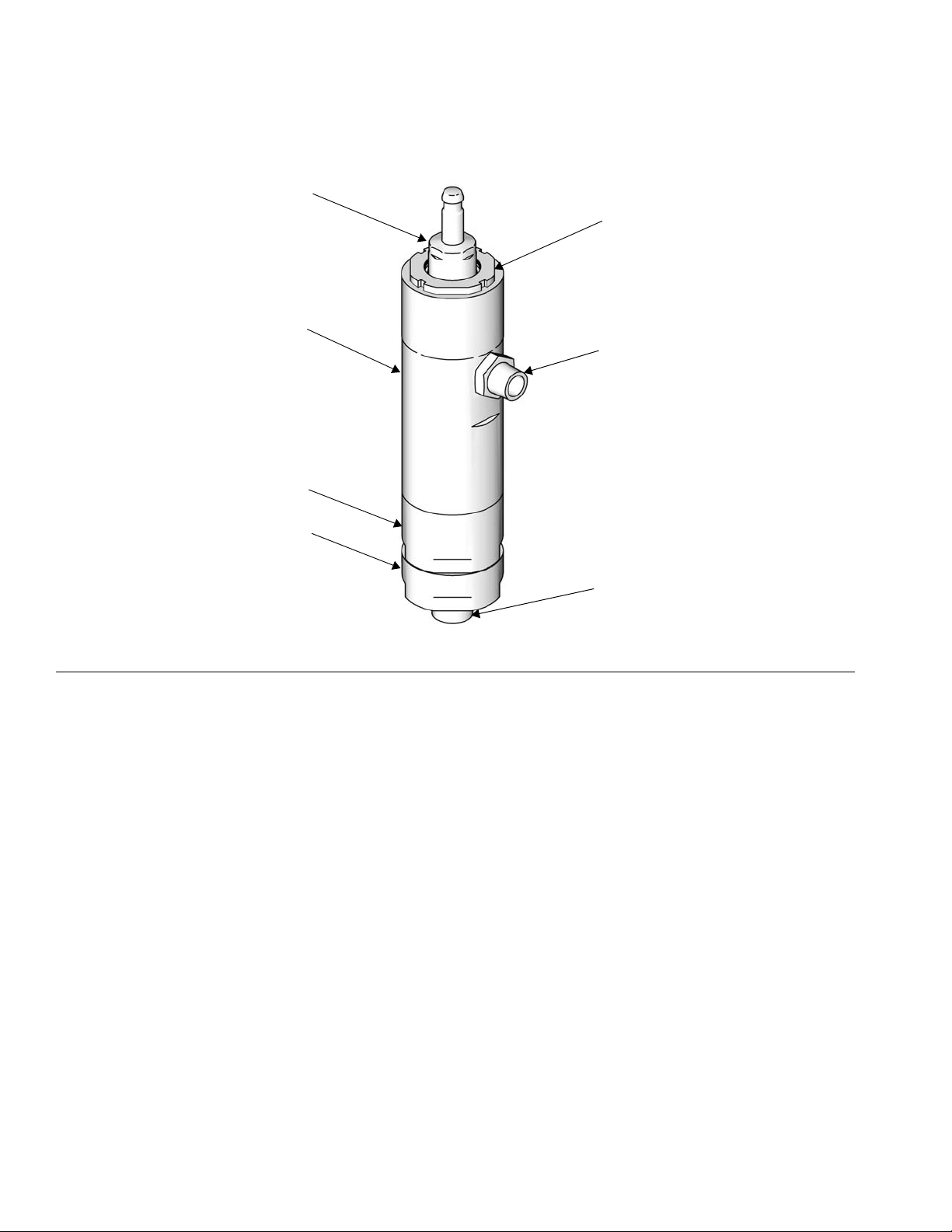
TI11643a
TI11645
LW025A
LW150A
Merkur
®
312792G
Displacement Pump
For use with high-performance finishing and coating pumps in hazardous and
non-hazardous locations. For professional use only.
Important Safety Instructions
Read all warnings and instructions in this manual.
For complete warnings and instructions see your
pump or package manual. Hazard symbols refer to
specific procedure risks. Save all instructions.
See page 3 for model information, including maximum working pressures.
EN
Page 2

Related Manuals
Contents
Related Manuals . . . . . . . . . . . . . . . . . . . . . . . . . . . 2
Models . . . . . . . . . . . . . . . . . . . . . . . . . . . . . . . . . . . 3
Component Identification . . . . . . . . . . . . . . . . . . . . 4
Repair . . . . . . . . . . . . . . . . . . . . . . . . . . . . . . . . . . . . 5
General Information . . . . . . . . . . . . . . . . . . . . . . 5
Preparation . . . . . . . . . . . . . . . . . . . . . . . . . . . . . 5
Disassembly . . . . . . . . . . . . . . . . . . . . . . . . . . . . 5
Reassembly . . . . . . . . . . . . . . . . . . . . . . . . . . . . 6
Related Manuals
Manual Description
312796
312794 Merkur Pump Assembly
312797 Merkur Spray Packages, ambient, AA
312798 Merkur Electrostatic Spray Packages
313255 Merkur Heated Spray Packages
™
NXT
Air Motor
and Airless
Parts . . . . . . . . . . . . . . . . . . . . . . . . . . . . . . . . . . . . . 9
Standard Repair Kits . . . . . . . . . . . . . . . . . . . . . . . 11
Optional Kits . . . . . . . . . . . . . . . . . . . . . . . . . . . . . . 11
Dimensions . . . . . . . . . . . . . . . . . . . . . . . . . . . . . . . 12
Technical Data . . . . . . . . . . . . . . . . . . . . . . . . . . . . 13
Graco Standard Warranty . . . . . . . . . . . . . . . . . . . 14
Graco Information . . . . . . . . . . . . . . . . . . . . . . . . . 14
2 312792G
Page 3
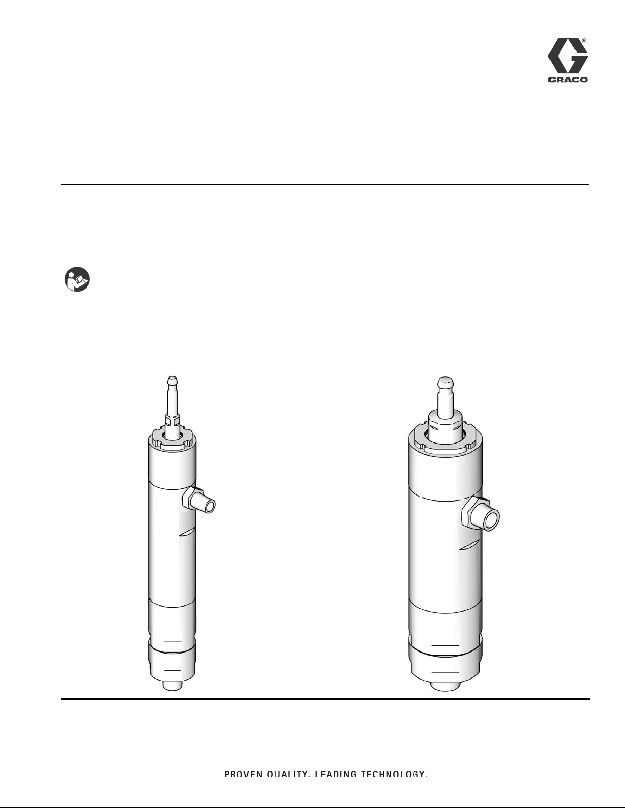
Models
ti12415a
Check your displacement pump’s identification marking for the 6-digit part
number. Use the following matrix to define the construction of your displacement pump. For example, displacement pump model LW025A represents a
wet-cup style stainless steel displacement pump, 25 cc, with a Chromex
coated rod and 3 UHMWPE, 2 PTFE packings.
To order replacement parts, see Parts section starting on page 9. The digits in
the matrix do not correspond to the reference numbers in the Parts drawings
and lists.
LW 025 A
Third, Fourth, and Fifth
Digits
First Digit
Second Digit
(Description)
(Displacement Pump
Volume Per Cycle* in cc)
(Packings; Displacement Rod Coating)
Sixth Digit
Models
L
(Lower)
W
Wet-cup style,
stainless steel
025 A
050
075
100
125
150
* Cycle refers to combination of one upstroke and one downstroke.
Maximum Working
Pressure
Model, Series
LW025A, Series A
LW050A, Series A
LW075A, Series A
LW100A, Series A
psi (MPa, bar) Fluid Inlet Fluid Outlet
3000 (20.7, 207) 1/2 in. npt 3/8 in. npt
4500 (31.0, 310) 3/4 in. npt 3/8 in. npt
4800 (33.1, 331) 3/4 in. npt 3/8 in. npt
3600 (24.8, 248) 3/4 in. npt 3/8 in. npt
3 UHMWPE, 2 PTFE; Chromex™
LW125A, Series A
LW150A, Series A
312792G 3
2900 (20.0, 200) 1 in. npt 1/2 in. npt
2400 (16.5, 165) 1 in. npt 3/4 in. npt
Page 4
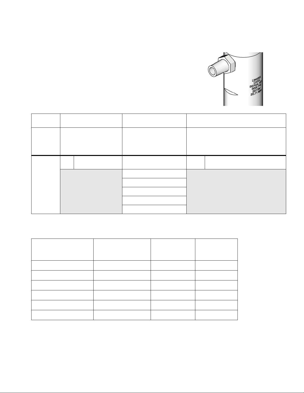
Component Identification
A
B
D
E
G
F
ti11645a
C
Component Identification
FIG. 1. Component Identification
Key:
A Piston/Rod Assembly
BWet Cup
C Fluid Outlet
D Fluid Inlet
E Lower Cylinder
F Upper Cylinder
G Intake Valve
4 312792G
Page 5
Repair
ti12918a
General Information
Repair
Threads are very sharp. Use a rag to protect hands.
NOTICE
Reference numbers and letters in parentheses in the
text refer to the callouts in the figures and the parts
drawing.
Always use Genuine Graco Parts and Accessories,
available from your Graco distributor. If you supply
your own accessories, be sure they are adequately
sized and pressure rated for your system.
Preparation
Follow all warnings and instructions in your pump manual for the following preliminary steps:
1. Flush the equipment.
2. Relieve the pressure.
3. Remove the displacement pump from the pump
assembly.
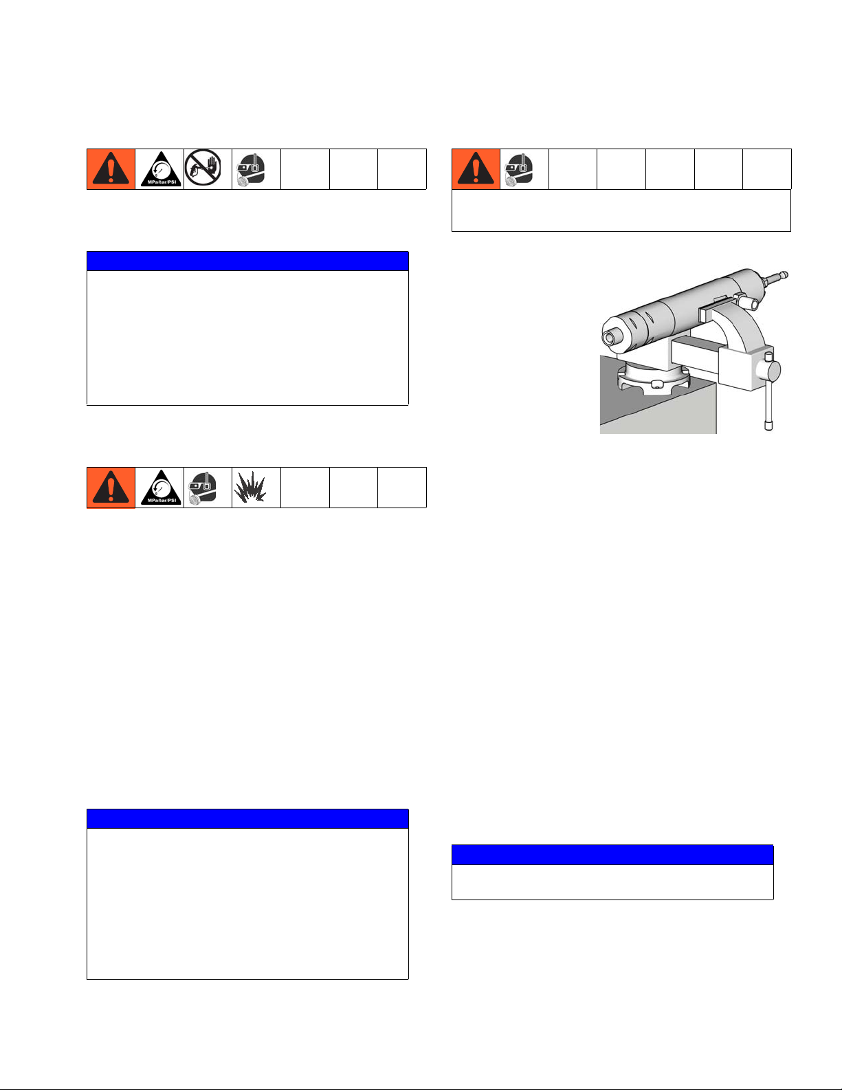
1. Place cylinder (1)
sideways in a vise
with soft jaws.
2. Use an adjustable
wrench on hex of
intake housing
(23) to unscrew it
from the lower
cylinder (2).
Loosen vice
briefly and tip out
the ball (24◆).
3. Remove the seat (22†) and use an o-ring pick to
remove the seal (26†) from the intake housing. See
F
IG. 7.
4. Use an adjustable wrench on hex of lower cylinder
(2) to remove it from the upper cylinder (1) and slide
it straight off the pump. Be careful not to damage
the piston/rod assembly (3).
5. Remove the o-ring (21*†) from the top of the lower
cylinder.
6. Loosen the wet cup (5).
Disassembly
Lay out all removed parts in sequence to ease
reassembly. Clean all parts with a compatible solvent
and inspect them for wear or damage.
NOTICE
Repair Kits are available. See the chart on page 11
to order the correct kit(s) for your pump.
• Parts included in the Seal Repair Kit are marked
with an *, for example 8*.
• Parts included in the Seat Repair Kit are marked
with a †.
• Parts included in the Check Ball Kit are marked
with a ◆.
312792G 5
7. Pull the piston/rod assembly out the bottom of the
upper cylinder. Remove the spring (10*), piston
packings (12* and 13*) and glands (11* and 14*).
8. Remove the wet cup (5).
9. Remove the throat packings (7*, 8*) and glands (6*,
9*) from the bottom of the wet cup.
NOTICE
The jam nut can remain attached to the upper cylinder.
10. Remove the spring (4*) from the top of the upper
cylinder (1).
Page 6

Repair
ti12782a
*28
*9
*7
*8
*7
*8
*7
*6
5
ti11691a
Lips must
face down.
*27
11. Remove the wet cup seal (27*) and the upper cylinder seal (28*).
12. Clamp the piston in a vice. Use a hex wrench to
remove the nut (17†) from end of piston.
• LW025A–LW050A: 7 mm (1/4 in.) hex
• LW075A–LW150A: 13 mm (1/2 in.) hex
Reassembly
1. Clean and inspect all parts.
NOTICE
Replace all o-rings removed from the pump. Compressed o-rings may cause the pump to leak.
2. Lubricate and install new wet cup seal (27*) and
upper cylinder seal (28*).
3. Assemble the female gland (9*), v-packings (7*, 8*),
and male gland (6*), as shown. Alternate the
v-packings with the lips facing down. Lubricate the
packings. Install the packing stack into the wet
cup (5).
F
IG. 2. Remove Flow-Through Nut
13. Remove the o-ring (18†), seat (15†) and ball (16◆).
See F
IG. 5.
F
IG. 3. Replace Throat Packings
4. Install the spring (4*) in the top of the upper cylinder.
NOTICE
All threads, packings, and seals must be well lubricated. Use Lubriplate (Graco Part Number 285791)
or a similar product.
5. Lubricate the threads and screw the wet cup (5) into
the upper cylinder (1), hand tight.
6 312792G
Page 7

Repair
ti11693a
10*
11*
12*
13*
12*
13*
14*
12*
5
4*
1
Lips must
face up
3
◆16
†15
†18
†17
ti11692a
6. Assemble the male gland (11*), v-packings (12*,
13*), and female gland (14*), as shown. Alternate
the v-packings, with the lips facing up. Lubricate the
packings. Install the spring (10*) and packing stack
into the bottom of the upper cylinder (1).
8. Place piston in vice and torque flow-through nut
(17†) as specified in the following table.
Displacement Pump Torque
LW025A–LW050A 58-62 ft-lb (78-84 N•m)
LW075A–LW150A 78-82 ft-lb (105-111 N•m)
F
IG. 4. Replace piston packings.
7. Place the ball (16◆) in the piston body. Install the
seat (15†) and o-ring (18†). Lubricate the o-ring and
the threads of the flow-through nut (17†). Screw the
flow-through nut (17†) into the piston/rod
assembly (3).
312792G 7
F
IG. 5. Replace piston ball and seat.
9. Push the piston/rod assembly (3) into the upper
cylinder (1).
10. Lubricate and install the seal (21*) on the top of the
lower cylinder (2).
11. Lubricate the threads and screw the lower cylinder
(2) onto the upper cylinder (1). Torque to 95-105
ft-lb (128-142 N•m).
Page 8

Repair
1
3
21*
2
ti12414a
25*†
25✓
24✓
22✓
26✓
23
ti11694a
14. Lubricate the seal (25*†) and threads of the lower
cylinder (2). Place the ball (24◆) on the seat (22†).
FIG. 7. Replace intake ball and seat.
15. Keep upright to screw the housing (23) into the
lower cylinder (2) hand tight, so the seat remains
firmly in place. Then clamp the cylinder in a vice and
torque as specified in the following table.
F
IG. 6. Assemble piston/rod assembly and cylinders.
12. Lubricate and install the seal (25*†) on the bottom of
the lower cylinder (2).
13. Install the o-ring (26†) and intake seat (22†) into the
top of the inlet housing. Lubricate the o-ring. The
seat (22†) is reversible. Turn over or replace as
needed.
Displacement Pump Torque
LW025A–LW050A 58-62 ft-lb (78-84 N•m)
LW075A–LW150A 78-82 ft-lb (105-111 N•m)
16. Torque wet cup (5) to 58-62 ft-lb (78-84 N•m).
8 312792G
Page 9

Parts
5
27*
28*
9*
7*
8*
7*
8*
7*
6*
1
16◆
15†
18*†
17
†
10*
11*
12*
13*
12*
13*
12*
14*
21*
†
25*†
24◆
22†
26*†
23
2
3
Lubricate.
Torque to 95-105 ft-lb (128-142 N•m)
3
Torque to 58-62 ft-lb (78-84 N•m)
Torque varies by lower size.
LW025A-LW050A: 58-62 ft-lb (78-84 N•m)
LW075A-LW150A: 78-82 ft-lb (105-111 N•m)
3
35
36
37
ti11644a
4*
32
Apply thread lubricant.
4
1
2
1
1
1
1
1
1
5
5
5
5
5
2
4
4
1
33*
5
2
1
Parts
312792G 9
Page 10

Parts
Ref. Description Part Qty.
CYLINDER KIT, upper; includes
1
1
21, 28, 32, and 33 (qty. 1)
LW025A 24A813
LW050A 24A814
LW075A 24A815
LW100A 24A816
LW125A 24A817
LW150A 24A818
CYLINDER KIT, lower; includes
2
1
21 and 25
LW025A 24A822
LW050A 24A823
LW075A 24A824
LW100A 24A825
LW125A 24A826
LW150A 24A827
PISTON/ROD, assembly;
3
1
includes 15-18, 36, and
37 (qty. 1)
LW025A 24A643
LW050A 24A644
LW075A 24A645
LW100A 24A646
LW125A 24A647
LW150A 24A648
SPRING, throat
4*
WET CUP; includes 27 and 28
5
-----
1
1
(qty. 1 each)
LW025A 24A807
LW050A 24A808
LW075A 24A809
LW100A 24A810
LW125A 24A811
LW150A 24A812
GLAND, male, throat ----- 1
6*
PACKING, throat, UHMWPE ----- 3
7*
PACKING, throat, PTFE ----- 2
8*
GLAND, female, throat ----- 1
9*
SPRING, piston ----- 1
10*
GLAND, male, piston ----- 1
11*
PACKING, piston, UHMWPE ----- 3
12*
PACKING, piston, PTFE ----- 2
13*
GLAND, female, piston ----- 1
14*
SEAT, piston valve, tungsten
15†
----- 1
carbide
BALL, piston valve, 440 stain-
16◆
----- 1
less steel
NUT, flow through ----- 1
17†
O-RING, piston ----- 1
18*†
Ref. Description Part Qty.
O-RING, lower cylinder ----- 1
21*†
SEAT, intake valve, tungsten
22†
----- 1
carbide
INTAKE VALVE KIT; includes 26 1
23
LW025A 24A834
LW050A 24A835
LW075A 24A836
LW100A 24A837
LW125A 24A838
LW150A 24A839
BALL, intake valve, 440 stainless
24◆
----- 1
steel
O-RING, lower cylinder ----- 2
25*†
O-RING, intake valve ----- 1
26*†
O-RING, wet cup; package of 10 1
27*
LW025A 24A630
LW050A-LW075A 24A631
LW100A 24A632
LW125A-LW150A 24A633
O-RING, wet cup ----- 1
28*
FITTING, outlet, 3/8-18 npt X
32
1
3/4-16 unf; includes 33 (qty. 1)
LW025A-LW100A 24A840
LW125A 24A841
LW150A 24A842
O-RING, outlet; package of 10 1
33*
LW025A-LW100A 24E457
LW125A 24E458
LW150A 24E459
JAM NUT 1
35
LW025A 24A634
LW050A 24A635
LW075A 24A636
LW100A 24A637
LW125A 24A638
LW150A 24A639
NUT, coupling 1
36
LW025A 15M758
LW050A-LW150A 15T311
COLLAR, coupling; pkg. of 10 1
37
LW025A 24A618
LW050A-LW150A 24A619
----- Not sold separately.
* Included in Seal Repair Kit. See page 11.
† Included in Seat Repair Kit. 316 stainless steel seats
also are available. See page 11.
◆ Included in Check Ball Kit. Tungsten carbide and 316
stainless steel check balls also are available. See
page 11.
10 312792G
Page 11

Standard Repair Kits
Standard Repair Kits
Kit Description LW025A LW050A LW075A LW100A LW125A LW150A
* Seal Repair Kit
Throat v-packings (7* and 8*) and glands (6*
and 9*), piston v-packings (12* and 13*) and
glands (11* and 14*), o-rings (18*, 21*, 25*, 26*
27*, 28*, and 33*), and springs (4*and 10*)
V-Packing Repair Kit
Throat v-packings (7* and 8*), piston v-packings
(12* and 13*, and o-rings (18*, 21*, 25*, 26*
27*, 28*, and 33*)
† Tungsten Carbide Seat Repair Kit
Seats (15† and 22†), o-rings (18†, 21†, 25†,
and 26†), and flow-through nut (17†)
24A251 24A252 24A253 24A254 24A255 24A256
--- --- 24R167 24R168 --- ---
24A781 24A782 24A783 24A784 24A785 24A786
◆ 440 Stainless Steel Check Ball Kit
Piston ball (16◆) and intake ball (24◆)
Wet-Cup O-Ring (27)
Package of 10
Coupling Collars (37)
Package of 10
24A261 24A261 24A263 24A264 24A264 24A264
24A630 24A631 24A631 24A632 24A633 24A633
24A618 24A619 24A619 24A619 24A619 24A619
Optional Kits
Kit Description LW025A LW050A LW075A LW100A LW125A LW150A
Reinforced PTFE V-Packing Kit**
Reinforced PTFE throat packings and glands,
reinforced PTFE piston packings and glands,
o-rings, and springs
†316 Stainless Steel Seat Repair Kit***
Seats (15† and 22†), o-rings (18†, 21†, 25†,
and 26†), and flow-through nut (17†)
◆Check Ball Kit
Piston ball (16◆) and intake ball (24◆)
24J852 24J853 24J854 24J855 24J856 24J857
24A794 24A795 24A796 24A797 24A798 24A799
316 Stainless Steel***
Tungsten Carbide
** Use with materials that cause chemical compatibility concerns with UHMWPE, such as acid catalyst materials.
*** Replaces standard kits for high corrosive applications.
312792G 11
24P612 24P612 24P613 24P614 24P614 24P614
24A667 24A667 24A669 24A670 24A670 24A670
Page 12

Dimensions
C
C
A
A
Model LW025A Model LW150A
ti11643a
ti11645a
B
B
Dimensions
F
IG. 8
Displacement Pump Dimensions
Displacement
Pump
LWO25A
LW050A
LW075A
LW100A
LW125A
LW150A
* Height measured at mid-stroke.
A
(Height*)
in. (mm)
14.9 (378) 1/2 in. 3/8 in. 9.0 (4.1)
14.8 (376) 3/4 in. 3/8 in. 13.2 (6)
15.4 (391) 3/4 in. 3/8 in. 15.3 (6.9)
15.4 (391) 3/4 in. 3/8 in. 18.6 (8.4)
15.6 (396) 1 in. 1/2 in. 21.2 (9.6)
15.6 (396) 1 in. 3/4 in. 22.0 (10)
B
(Inlet Size)
in. npt
C
(Outlet Size)
in. npt
Weight
lbs (kg)
12 312792G
Page 13

Technical Data
Technical Data
Maximum fluid working pressure
LW025A . . . . . . . . . . . . . . . . . . . . . . . . . . . . . . . . . . . 3000 psi (20.7 MPa, 207 bar)
LW050A . . . . . . . . . . . . . . . . . . . . . . . . . . . . . . . . . . . 4500 psi (33.1 MPa, 310 bar)
LW075A . . . . . . . . . . . . . . . . . . . . . . . . . . . . . . . . . . . 4800 psi (33.1 MPa, 331 bar)
LW100A . . . . . . . . . . . . . . . . . . . . . . . . . . . . . . . . . . . 3600 psi (24.8 MPa, 248 bar)
LW125A . . . . . . . . . . . . . . . . . . . . . . . . . . . . . . . . . . . 2900 psi (20.0 MPa, 200 bar)
LW150A . . . . . . . . . . . . . . . . . . . . . . . . . . . . . . . . . . . 2400 psi (16.5 MPa, 165 bar)
Maximum operating temperature . . . . . . . . . . . . . . . . . . . 160°F (71°C)
Fluid inlet size
LW025A . . . . . . . . . . . . . . . . . . . . . . . . . . . . . . . . . . . 1/2 in. npt
LW050A– LW100A. . . . . . . . . . . . . . . . . . . . . . . . . . . 3/4 in. npt
LW125A–LW150A . . . . . . . . . . . . . . . . . . . . . . . . . . . 1 in. npt
Fluid outlet size
LW025A–LW100A . . . . . . . . . . . . . . . . . . . . . . . . . . . 3/8 in. npt
LW125A . . . . . . . . . . . . . . . . . . . . . . . . . . . . . . . . . . . 1/2 in. npt
LW150A . . . . . . . . . . . . . . . . . . . . . . . . . . . . . . . . . . . 3/4 in. npt
Stroke length . . . . . . . . . . . . . . . . . . . . . . . . . . . . . . . . . . 2.5 in.
Wetted parts . . . . . . . . . . . . . . . . . . . . . . . . . . . . . . . . . . . stainless steel, tungsten carbide, UHMWPE, PTFE
312792G 13
Page 14

Graco Standard Warranty
Graco warrants all equipment referenced in this document which is manufactured by Graco and bearing its name to be free from defects in
material and workmanship on the date of sale to the original purchaser for use. With the exception of any special, extended, or limited warranty
published by Graco, Graco will, for a period of twelve months from the date of sale, repair or replace any part of the equipment determined by
Graco to be defective. This warranty applies only when the equipment is installed, operated and maintained in accordance with Graco’s written
recommendations.
This warranty does not cover, and Graco shall not be liable for general wear and tear, or any malfunction, damage or wear caused by faulty
installation, misapplication, abrasion, corrosion, inadequate or improper maintenance, negligence, accident, tampering, or substitution of
non-Graco component parts. Nor shall Graco be liable for malfunction, damage or wear caused by the incompatibility of Graco equipment with
structures, accessories, equipment or materials not supplied by Graco, or the improper design, manufacture, installation, operation or
maintenance of structures, accessories, equipment or materials not supplied by Graco.
This warranty is conditioned upon the prepaid return of the equipment claimed to be defective to an authorized Graco distributor for verification of
the claimed defect. If the claimed defect is verified, Graco will repair or replace free of charge any defective parts. The equipment will be returned
to the original purchaser transportation prepaid. If inspection of the equipment does not disclose any defect in material or workmanship, repairs will
be made at a reasonable charge, which charges may include the costs of parts, labor, and transportation.
THIS WARRANTY IS EXCLUSIVE, AND IS IN LIEU OF ANY OTHER WARRANTIES, EXPRESS OR IMPLIED, INCLUDING BUT NOT LIMITED
TO WARRANTY OF MERCHANTABILITY OR WARRANTY OF FITNESS FOR A PARTICULAR PURPOSE.
Graco’s sole obligation and buyer’s sole remedy for any breach of warranty shall be as set forth above. The buyer agrees that no other remedy
(including, but not limited to, incidental or consequential damages for lost profits, lost sales, injury to person or property, or any other incidental or
consequential loss) shall be available. Any action for breach of warranty must be brought within two (2) years of the date of sale.
GRACO MAKES NO WARRANTY, AND DISCLAIMS ALL IMPLIED WARRANTIES OF MERCHANTABILITY AND FITNESS FOR A
PARTICULAR PURPOSE, IN CONNECTION WITH ACCESSORIES, EQUIPMENT, MATERIALS OR COMPONENTS SOLD BUT NOT
MANUFACTURED BY GRACO. These items sold, but not manufactured by Graco (such as electric motors, switches, hose, etc.), are subject to
the warranty, if any, of their manufacturer. Graco will provide purchaser with reasonable assistance in making any claim for breach of these
warranties.
In no event will Graco be liable for indirect, incidental, special or consequential damages resulting from Graco supplying equipment hereunder, or
the furnishing, performance, or use of any products or other goods sold hereto, whether due to a breach of contract, breach of warranty, the
negligence of Graco, or otherwise.
FOR GRACO CANADA CUSTOMERS
The Parties acknowledge that they have required that the present document, as well as all documents, notices and legal proceedings entered into,
given or instituted pursuant hereto or relating directly or indirectly hereto, be drawn up in English. Les parties reconnaissent avoir convenu que la
rédaction du présente document sera en Anglais, ainsi que tous documents, avis et procédures judiciaires exécutés, donnés ou intentés, à la suite
de ou en rapport, directement ou indirectement, avec les procédures concernées.
Graco Information
For the latest information about Graco products, visit www.graco.com.
For patent information, see www.graco.com/patents.
TO PLACE AN ORDER, contact your Graco distributor or call to identify the nearest distributor.
Phone: 612-623-6921 or Toll Free: 1-800-328-0211 Fax: 612-378-3505
All written and visual data contained in this document reflects the latest product information available at the time of publication.
GRACO INC. AND SUBSIDIARIES • P.O. BOX 1441 • MINNEAPOLIS MN 55440-1441 • USA
Copyright 2008, Graco Inc. All Graco manufacturing locations are registered to ISO 9001.
Graco reserves the right to make changes at any time without notice.
Original instructions. This manual contains English. MM 312792
Graco Headquarters: Minneapolis
International Offices: Belgium, China, Japan, Korea
www.graco.com
Revision G - May 2013
 Loading...