

Page 1
Instruction Manual
Full Line Software with
Reynolds & Reynolds Certified
Interface
For use with Graco Matrix Electronic Meter and Tank Level Monitor Components.
312353B
EN
Graco Inc. P.O. Box 1441 Minneapolis, MN 55440-1441
Copyright 2007, Graco Inc. is registered to I.S. EN ISO 9001
Page 2

Contents
System Requirements . . . . . . . . . . . . . . . . . . . . . . . 3
General Matrix System Specifications . . . . . . . . 3
PC Hardware Requirements . . . . . . . . . . . . . . 3
PC Software Requirements . . . . . . . . . . . . . . . 4
Pop-Up Blocker . . . . . . . . . . . . . . . . . . . . . . . . . . 4
Software Firewalls . . . . . . . . . . . . . . . . . . . . . . . . 6
Windows XP Security . . . . . . . . . . . . . . . . . . . . . 7
Installation Instructions . . . . . . . . . . . . . . . . . . . . . 8
Stand Alone Configuration . . . . . . . . . . . . . . . . . 8
Networked Configurations . . . . . . . . . . . . . . . . . . 8
Browser Configuration . . . . . . . . . . . . . . . . . . . . . 9
Setup Path 1- Typical (Matrix Server and Client) 9
HASP Key Driver Setup Program . . . . . . . . . 12
Matrix Server and Client Shortcuts . . . . . . . . 13
Setup Path 2 - Matrix Client Only. . . . . . . . . . . . 13
Matrix Client Only Shortcuts . . . . . . . . . . . . . 16
Sun Java Runtime . . . . . . . . . . . . . . . . . . . . . . . 17
Clock and Time Zone Settings . . . . . . . . . . . 18
MatrixLogs Folder . . . . . . . . . . . . . . . . . . . . . . . 18
How to Turn Off Hibernation
Mode in Windows XP . . . . . . . . . . . . . . . . . . 19
Software Installation Troubleshooting . . . . . . . . 21
Uninstalling Matrix on Windows XP . . . . . . . . . 24
Operator Screens . . . . . . . . . . . . . . . . . . . . . . . . . 25
Meter Dispense Information . . . . . . . . . . . . . . . 25
Tank Level Information . . . . . . . . . . . . . . . . . . . 26
Battery Level Information . . . . . . . . . . . . . . . . . 27
Entering Work Orders . . . . . . . . . . . . . . . . . . . . 27
Work Orders and the Matrix/R & R Interface . 28
Work Order Pop-up Windows . . . . . . . . . . . . 30
System Administrator Screens . . . . . . . . . . . . . . 32
Matrix System Setup . . . . . . . . . . . . . . . . . . . . . 32
System Configuration . . . . . . . . . . . . . . . . . . . . 33
Security Level (Global Setting) . . . . . . . . . . . 33
System Emergency Code . . . . . . . . . . . . . . . 33
Unit of Measure (English or Metric) . . . . . . . . 34
Edit Contact Information. . . . . . . . . . . . . . . . . 34
Transceiver Setup . . . . . . . . . . . . . . . . . . . . . . . 35
Transceiver Power-up . . . . . . . . . . . . . . . . . . 35
Confirm PC/Transceiver Communication. . . . 35
Matrix Client PC Setup . . . . . . . . . . . . . . . . . . . 36
Add a Client PC to the Matrix System . . . . . . 37
System User Setup . . . . . . . . . . . . . . . . . . . . . . 38
Adding a New User . . . . . . . . . . . . . . . . . . . . . . 38
Modify User Profile. . . . . . . . . . . . . . . . . . . . . 38
Changing User Information. . . . . . . . . . . . . . . 39
Removing a User . . . . . . . . . . . . . . . . . . . . . 39
Tank Setup . . . . . . . . . . . . . . . . . . . . . . . . . . . . 39
Customized Fluid Setup . . . . . . . . . . . . . . . . 39
Adding a New Tank using a TLM . . . . . . . . . 40
2 312353B
Tank Shape Screen . . . . . . . . . . . . . . . . . . . . 41
Manual Tank Adjustment . . . . . . . . . . . . . . . . . . 42
Removing a Tank . . . . . . . . . . . . . . . . . . . . . . . . 42
Programming the Tank Level Monitor . . . . . . . . 43
Meter Setup . . . . . . . . . . . . . . . . . . . . . . . . . . . 45
Adding a Meter . . . . . . . . . . . . . . . . . . . . . . . 45
Modifying Meter Information . . . . . . . . . . . . . 45
Removing a Meter . . . . . . . . . . . . . . . . . . . . . 47
Meter Programming . . . . . . . . . . . . . . . . . . . . 47
E-Mail Setup . . . . . . . . . . . . . . . . . . . . . . . . . . 49
E-mail Configuration . . . . . . . . . . . . . . . . . . . 49
Adding an E-Mail Event . . . . . . . . . . . . . . . . . 50
Removing an E-Mail Event . . . . . . . . . . . . . . 50
R&R Interface . . . . . . . . . . . . . . . . . . . . . . . . . 51
Setup . . . . . . . . . . . . . . . . . . . . . . . . . . . . . . . 51
Dealer Management System (DMS) . . . . . . . 53
Fluids Configuration . . . . . . . . . . . . . . . . . . . . 55
Unit and Menu Pricing - Parts . . . . . . . . . . . . 55
Unit and Menu Pricing - Gas, Oil,
Grease (GOG) . . . . . . . . . . . . . . . . . . . . . . . . 60
Menu Pricing . . . . . . . . . . . . . . . . . . . . . . . . . 61
Non-Fluid Parts . . . . . . . . . . . . . . . . . . . . . . . . . 64
Return to Operating Screens . . . . . . . . . . . . . . 65
Matrix Reporter . . . . . . . . . . . . . . . . . . . . . . . . . . . 66
Production Data . . . . . . . . . . . . . . . . . . . . . . . . . 66
Starting Matrix Reporter . . . . . . . . . . . . . . . . 66
Creating a Report . . . . . . . . . . . . . . . . . . . . . 66
Saving Report Data to File . . . . . . . . . . . . . . 67
Printing Report Data . . . . . . . . . . . . . . . . . . . 67
Filtering Report Data . . . . . . . . . . . . . . . . . . . 67
Matrix Database Import and Export . . . . . . . . 67
Exporting the Matrix Database . . . . . . . . . . . 67
Importing a Matrix Database File . . . . . . . . . . 68
Database File Import Instructions . . . . . . . . . 68
Troubleshooting . . . . . . . . . . . . . . . . . . . . . . . . . . . 70
Appendix A - Matrix Network and Port Settings . 71
Edit Matrix Server Network Settings. . . . . . . . . . 71
Edit Matrix Client Network Settings . . . . . . . . . 72
Graco Standard Warranty . . . . . . . . . . . . . . . . . . . 74
Graco Phone Numbers . . . . . . . . . . . . . . . . . . . . . 74
Page 3

System Requirements
System Requirements
Matrix PC hardware requirements differ somewhat,
depending on how the system is configured. The system
might consist of a single PC, as previous versions of
Matrix were limited to, or it might consist of multiple PCs.
In the multiple-PC configuration, one PC is designated
to be the Matrix Server; all the rest are Matrix Clients.
The Matrix Server must support the Matrix-related activities of all the clients, and thus has a higher threshold of
minimum hardware requirements.
Graco strongly recommends that the end user’s IT
(Information Technology) representative be involved
in the following Matrix installation activities:
• Assist with the selection and/or purchase of the
Matrix PC. The PC must meet the performance
specifications listed under PC Hardware Require-
ments. If the Matrix PC will be connected to a Network with other PCs, the IT representative should
be contacted to properly configure the PC before
loading Matrix software.
• The IT representative should be present during
Matrix software loading on the day of Matrix installation.
This version of Matrix will support a network of up
to 25 Matrix Client PCs; more than 25 are not supported. Please call Graco if you require more than
25 client PCs.
PC Hardware Requirements
Standalone Matrix PC:
• 2 MHz Pentium 4 (or equivalent) processor
• 512 MB RAM, 1024x768 screen resolution
• 1 GB free hard disk space
•CD-ROM drive
• one available RS232 port
• one available USB port
•network card
• uninterruptible power supply (UPS).
• Some means of archiving Matrix production data
and backup database files over time is recommended--examples of hardware that can help with
this are a CD/RW or DVD-R/W drive, a USB flash
drive, or an accessible network drive.
General Matrix System Specifications
Matrix PC software supports systems using a single PC
(also referred to as a standalone PC) as well as multiple-PC systems.
Single PC (Standalone) Systems: Intended primarily
for applications that do not require interaction with
Matrix screens from multiple locations and have few
meters and tank level monitors, this type of system provides complete Matrix system functionality at one PC.
Multiple-PC (Networked) Systems: Using an existing
network, Matrix deployed in this fashion consists of a
single (dedicated) PC functioning as the Matrix Server
and one or more PCs functioning as Matrix Clients. The
Matrix system’s transceiver(s) are always connected to
the Matrix Server. This configuration is recommended
for applications where Matrix screen access from multiple physical locations is desired or there are large numbers of meters and tank level monitors.
Graco recommends that this PC be dedicated to
Matrix--i.e. it is not used for other purposes, like
running spreadsheet programs, sending e-mail,
etc.
Matrix Server PC in a multiple-PC system:
The same requirements as for the standalone PC,
except:
• 3.8 MHz Pentium 4 (or equivalent) processor
•1 GB RAM
Graco requires that this PC be dedicated to
Matrix--i.e. it is not used for other purposes, like
running spreadsheet programs, sending e-mail,
etc.
Matrix Client PC in a multiple-PC system:
2 MHz Pentium 4 (or equivalent) processor, 512 MB
RAM, 1024x768 screen resolution, 500 MB free hard
disk space, CD-ROM drive, network card.
312353B 3
Page 4

System Requirements
Serial Port
If the standalone Matrix PC or Matrix Server does not
have a physical serial port, a USB-to-serial port converter will be required. The converter selected is based
on the number of transceivers used in the system.
Graco recommends Edgeport converters, which are
available in 1, 4, or 8 port models (Edgeport/1, Edgeport/4, and Edgeport/8, respectively) and can be purchased from B & B Electronics Manufacturing Company
(www.bb-elec.com). Each model comes with a 3.3 foot
(1 meter) cable.
Uninterruptible Power Supply
An Uninterruptible Power Supply (UPS) is required in all
Matrix systems and is available from Graco (part no.
119425 for North American applications or part no.
120104 in Australia). This power supply provides continuous battery power to the PC during power interruption
and safely shuts down the PC, securing your Matrix software and preventing data corruption. Be sure the PC
and monitor are plugged into the battery back-up side of
the UPS during installation.
E-Mail
Matrix can send e-mail to responsible parties based on
certain bulk fluid tank conditions. If this feature is to be
used, an “always on” Internet connection or network
access to an outgoing mail server is required.
Sound Card
If the Parts Room Authorization feature of Matrix is
used, Matrix will generate an audible alert whenever
parts room authorization is received. A sound card in
the standalone Matrix PC or Matrix Server will allow this
to be heard by authorizing personnel.
PC Software Requirements
• Microsoft XP Professional or Home Edition (no other
operating system will work).
• Microsoft Internet Explorer (IE) version 6.0 or
higher.
• Java Runtime Environment (JRE) 1.4 or later. Version 1.4.2_04 is included in the Matrix setup; if
Matrix finds no JRE installed on the machine or it
finds an installed JRE older than 1.4, the user is
prompted to install this version. This check occurs
when the Matrix Client is started.
• If the installation is a multiple-PC system, the PCs
must be configured for the network they’re connected to.
• If the installation will use the e-mail feature of
Matrix, the standalone Matrix PC or Matrix Server
must have network access to an outgoing mail
server.
Pop-Up Blocker
Special Considerations for pop-up blockers
Summary: If a browser pop-up blocker is installed, it
must either be disabled or configured to allow pop-ups.
If it’s a single-PC system, the pop-up blocker must allow
pop-ups from http://127.0.0.1:8080. If it’s a multiple-PC
system, a pop-up blocker on the Matrix Server must
allow pop-ups from http://127.0.0.1:8080, while a
pop-up blocker on a Matrix Client must allow pop-ups
from http://MatrixServer:8080, where “Matrix Server” is
the computer name or IP address of the Matrix Server
PC. Recent versions of Internet Explorer have a built-in
pop-up blocker. You may have one or more browser toolbars that have pop-up blocker functionality, such as
those from Google and Yahoo. Security software programs, such as those provided by Symantec and
McAfee can contain pop-up blockers. It is fairly common
for PCs to have multiple pop-up blockers.
Matrix relies on the IE browser for its user interface. In
particular, Matrix uses browser pop-up windows extensively. The Matrix server includes a web server that generates the screens viewed within the browser. If the PC
has a pop-up blocker present, it can stop Matrix browser
windows from appearing. For Matrix windows to appear
properly, any pop-up blockers installed on the PC must
be configured to allow pop-ups from the Matrix server
(or be turned off).
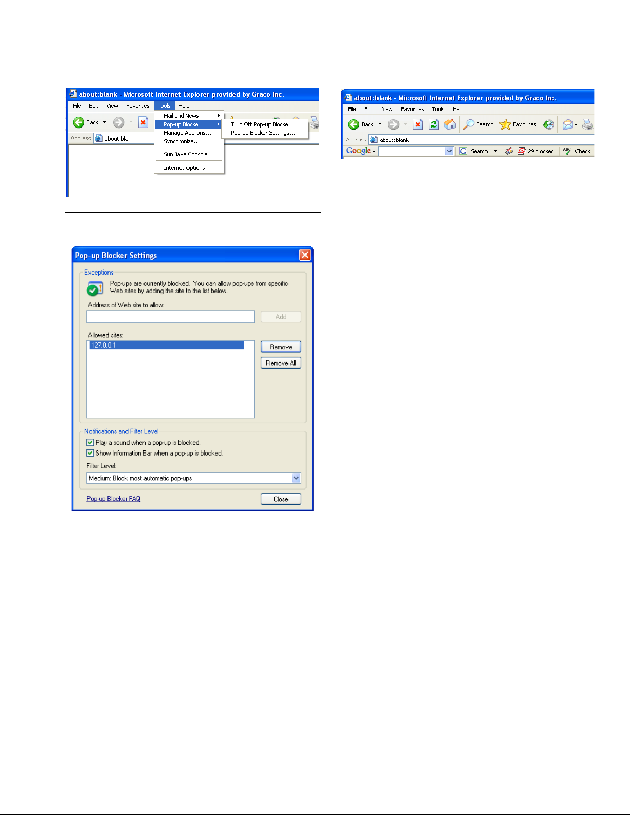
Pop-up blockers come in many forms. The version of IE
that comes with Windows XP Service Pack 2, for example, contains a built-in pop-up blocker.
The IE browser’s pop-up blocker can either be turned off
or configured to allow pop-ups by adding allowed sites in
the pop-up blocker settings of IE. In F
“Pop-up Blocker Settings”, the window shown in F
appears. This example is taken from a “default” installation of the Matrix software on a standalone PC (the
allowed site shown in F
Matrix).
IG. 2 was added manually, not by
IG. 1, if you select
IG. 2
4 312353B
Page 5
F
IG. 1
System Requirements
FIG. 3
Typically, when a PC has an active pop-up blocker and
the Matrix client is launched, a progress bar appears
briefly and disappears without any further visible indication of anything happening. This is usually an indication
that the PC has a pop-up blocker that is stopping the
Matrix window from appearing.
There are some general guidelines to follow to track
down the responsible pop-up blocker (there can easily
be multiple pop-up blockers present in any system). The
goal is to configure each pop-up blocker by either turning it off or telling it to allow pop-ups generated by the
Matrix server (while still blocking pop-ups from all other
sites). On a single-PC Matrix system, you should configure the pop-up blocker to allow pop-ups from server
address http://127.0.0.1. On multiple-PC systems, the
address to allow is that of the Matrix server, either its
host name or IP address.
F
IG. 2
Many toolbars that integrate with IE also contain pop-up
blockers, such as those available from Google and
Ya h o o. F
IG. 3 shows an example of the Google toolbar;
others are very similar.
Many pop-up blockers recognize the Control key on the
keyboard, if pressed while clicking on a Link, as a command to temporarily allow pop-ups originating from that
link’s source. To try this method, hold down the Control
key on the keyboard while double-clicking on the Matrix
Client Icon on the desktop. This works only for that particular pop-up instance, so it’s not a good long-term
solution.
General guidelines to find and configure pop-up
blockers:
First, open a blank IE browser window. Click on Tools in
the menu bar (F
IG. 1). Choose Turn O f f Po p-up
Blocker or configure the pop-up blocker to allow
pop-ups from the Matrix server.
If IE has been properly configured and the Matrix windows still do not appear, it’s time to look for pop-up
blockers from other vendors, starting with toolbars integrated with IE. In IE, click on View in the menu bar and
choose Toolbars (F
IG. 4).
312353B 5
Page 6
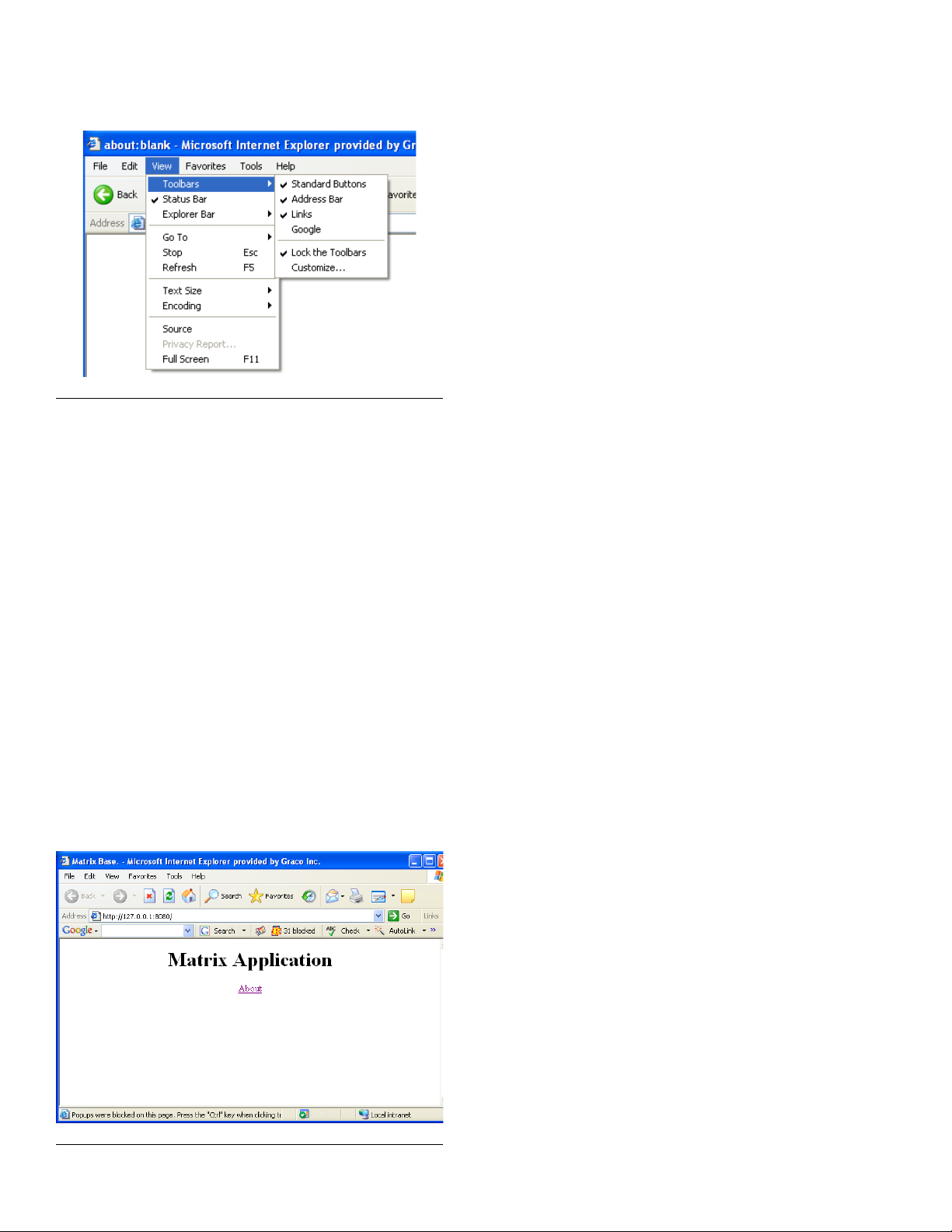
F
IG. 4
Toolbars integrated with IE usually show up in the list
here. Look for entries like Google, Yahoo, MSN, etc.
Make sure each of these is checked (which will cause
them to appear, usually underneath the address bar in
the browser window) and then confirm with each one
that it’s allowing pop-ups from the Matrix server.
The following example illustrates the Google toolbar, but
the others generally function in a very similar fashion.
Example: Assuming a Google toolbar is installed and
the system is a single PC Matrix system. The system
has been rebooted since the application was installed.
While the Matrix Client is in the Windows Startup folder,
no browser window appeared when Windows started.
Open a blank IE window. With the Google toolbar visible, enter http://127.0.0.1:8080 in the address bar and
press Enter. If a window like the one shown in F
appears, the Matrix server is running, but you have a
pop-up blocker.
IG. 5
System Requirements
Note the button in the middle of the Google toolbar that
shows 31 blocked; this is a count of how many pop-ups
the Google toolbar has stopped from appearing. Click
Button to make the toolbar allow pop-ups from the
address currently in the address bar. Close the browser
window and try launching Matrix via the Matrix client
desktop icon again.
The same series of steps is performed for multiple-PC
systems, only the address used is different--the address
of the Matrix server is used instead of 127.0.0.1.
Pop-up blockers are not limited to those included with
browser toolbars. Security products such as Norton
Internet Security also block pop-ups; refer to the vendor’s instructions on how to configure these software
programs.
Software Firewalls
Special Considerations for Firewalls
Summary: Any firewalls in use must allow TCP traffic on
ports 8080, 8083, 8084 and 3306 at the Matrix Server
and port 8082 at each Matrix Client. Matrix will not function properly if any of these ports are blocked. Windows
XP has a built-in firewall, which is turned on by default
(meaning that these ports are blocked) in Service Pack
2.
Any firewalls on the Matrix PC must allow network traffic
over several ports. PCs communicate with each other
via IP addresses and port numbers. An IP address can
be compared to the street address of an apartment
building, with a port number as a specific apartment
number in the building. The Matrix server and Matrix clients require certain ports be available/open in order to
communicate properly. These are the default TCP ports
required by the server and each client:
Matrix server:
Port 3306 - Matrix Database
Port 8080 - Matrix Web Server
Port 8083 - Matrix/R & R link
Port 8084 - Matrix Server
Matrix Client:
Port 8082 - Matrix Client
Communication to these ports can be blocked by firewall
software installed on your computer. Windows XP contains the Windows Firewall, but there are numerous
products provided by third parties such as Symantec
and McAfee that also provide firewall functionality. What
this means for Matrix is that any Firewalls) on the Matrix
F
IG. 5
6 312353B
PC must be either configured to allow traffic over these
ports or turned off altogether.
Page 7

System Requirements
The Matrix setup program offers to open these ports for
you in the Windows Firewall. It does not do this for other
firewall products.
Network traffic over these ports can also be blocked by
what is called a proxy server. Whether or not a network
has a proxy server that stops traffic on these ports, port
8080 in particular, is a question for the facility IT personnel.
The ports listed above are the defaults. If they are
changed for any reason, corresponding changes must
be made in the firewall settings to allow traffic over the
new port numbers. Changing the port numbers may be
necessary if, for example, another application is already
using these port numbers. Graco strongly recommends
that IT personnel familiar with the network are involved
with this configuration change.
Windows XP Security
The following security-related configuration settings are
not required but are recommended for all Matrix PCs:
1. Be sure a user name and password are required to
access the operating system.
2. Ensure the password-protected screensaver is
enabled and set to automatically activate after 15-30
minutes of system inactivity.
3. Change user passwords on a regular basis and
choose passwords that are difficult to guess.
4. Use anti-virus software to protect against viruses.
Some anti-virus programs are bundled with other
security software, including other security tools such
as pop-up blockers and firewalls. Take note of the
recommendations in the sections titled Special
Considerations for Pop-up Blockers on page 4
and Special Considerations for Firewalls on page
6.
5. Be sure the system is kept up to date with Microsoft
XP updates and service packs.
6. Use a firewall. As mentioned in the section titled
Special Considerations for Firewalls, take care to
allow for continued operation of Matrix by not blocking the network ports Matrix needs to use.
312353B 7
Page 8
Installation Instructions
p
p
Installation Instructions
IMPORTANT!
The user must be logged into Windows XP with
administrator privileges.
If an older version of Matrix is already installed, the older
version must be uninstalled before this one can be
installed. See the Matrix Software Instruction Manual
that accompanied your current Matrix installation for
instructions on how to uninstall Matrix.
Software Installation & Networking
This version of Matrix has two types of installations to
choose from in its setup program. One is the Matrix
Server & Client and the other is the Matrix Client. Select
Matrix Server & Client for single-PC installations and for
the one PC in a multiple-PC installation that will perform
the role of Matrix Server.
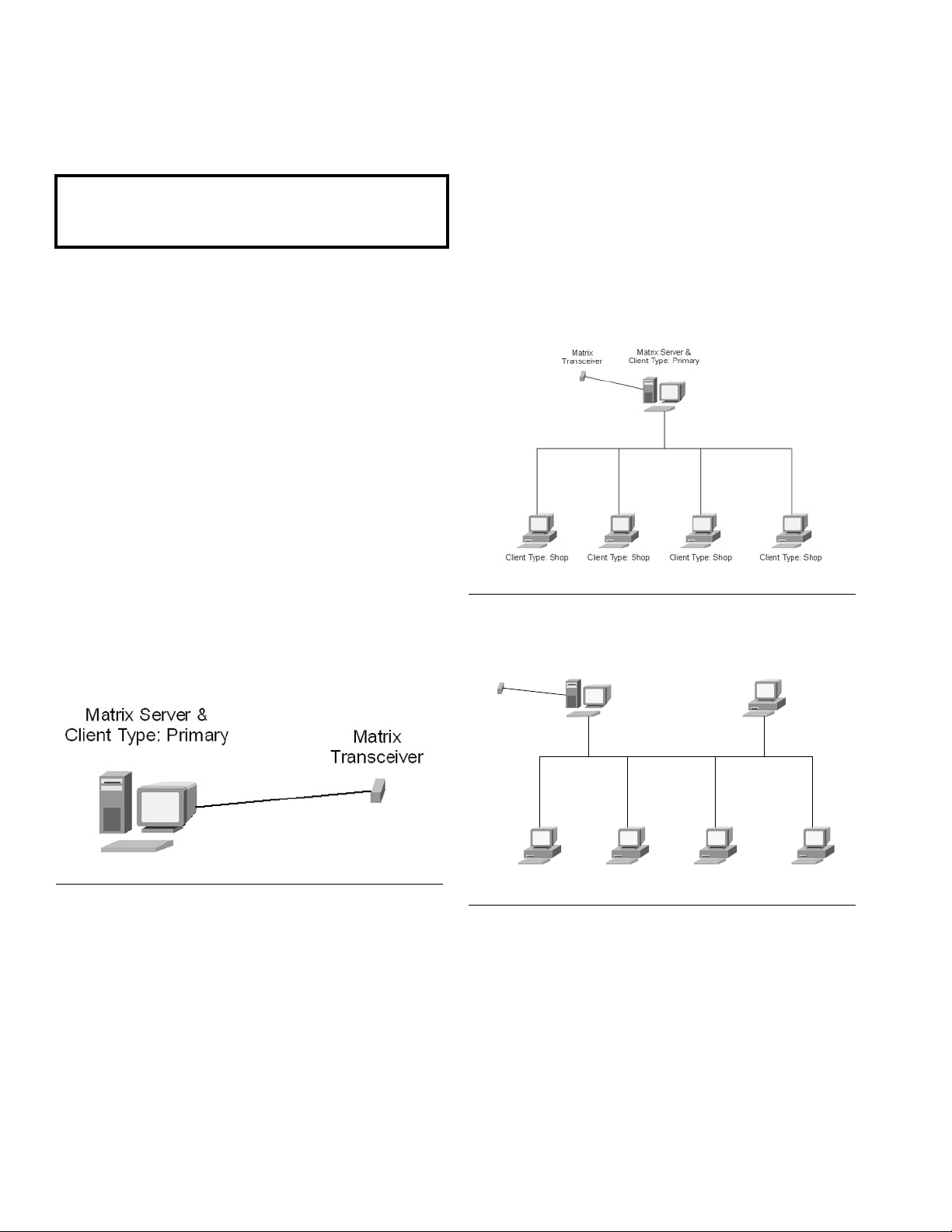
Stand Alone Configuration
This configuration (FIG. 6) has one PC dedicated to
Matrix system operation. The Matrix Server and Client
version of the software should be loaded to the PC.
Networked Configurations
Matrix Full Line Software with R & R Approved Interface
can be networked in the two configurations shown in
F
IG. 7 and FIG. 8. In FIG. 7, the server and primary client
are shown as one PC. In F
client are shown as separate pieces of hardware.
FIG. 7 Server and Primary Client as One PC
Matrix Server &
Matrix
Transceiver
Client Type: Shop
IG. 8, the server and primary
Client Type: Primary
F
IG. 6 Stand Alone Configuration
Follow setup path 1 beginning on page 9.
Client Type: ShopClient Type: ShopClient Type: Sho
IG. 8 Server and Primary Client Separate
F
Client Type: Sho
Follow setup path 1, beginning on page 9, on the PC
designated as the Matrix Server and setup path 2,
beginning on page 13, for all other PCs in the system.
8 312353B
Page 9
Installation Instructions
Browser Configuration
Prior to running the setup program, ensure that IE is
configured properly.
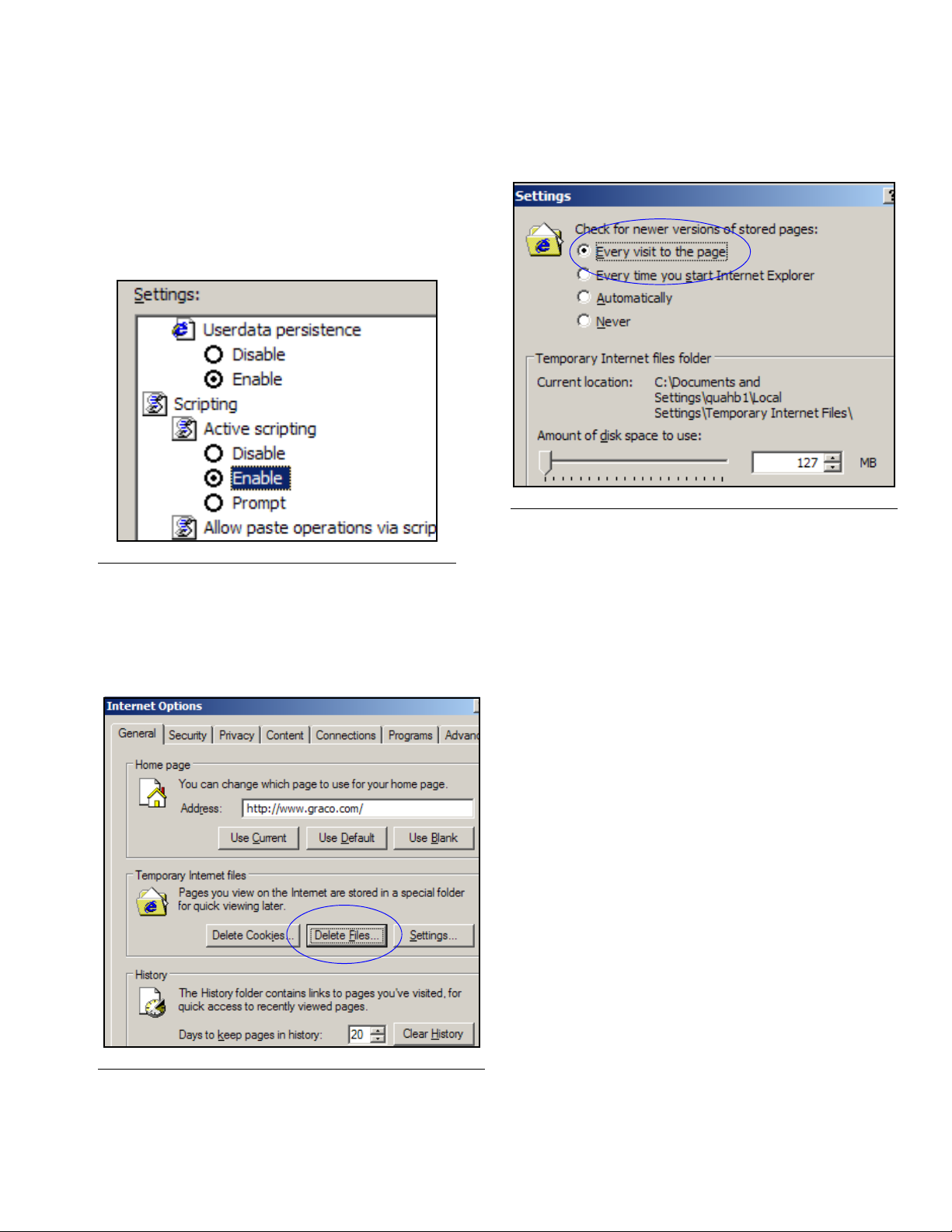
Open IE and verify that active scripting is enabled. This
setting is typically found in Tools / Internet Options /
Security Settings / Custom selection (F
F
IG. 9 Internet Java Script Security Settings
1. In the Temporary Internet Files section of the Internet Options box, click Delete Files. Select the
Delete All Offline Content check box.
Click OK (F
IG. 10).
IG. 9).
2. Click Settings. Select Every visit to the page.
Click OK (F
FIG. 11 Internet Page Settings
3. Select the Content tab and click the AutoComplete
Button. Clear the check marks from all the boxes.
Click the Clear Forms Button and select Yes to
any pop-up screens. Click the Clear Passwords
Button and select Yes to any pop-up screens. Click
OK.
Click OK to close the Internet Options dialog box.
IG. 11).
IG. 10 Internet Options General
F
Setup Path 1- Typical (Matrix Server and Client)
FIG. 12 through FIG. 25.
1. Log into Windows XP as administrator.
2. Configure IE according to the Browser Configuration
section.
3. Insert the Matrix CD in the CD-ROM drive.
312353B 9
Page 10
Installation Instructions
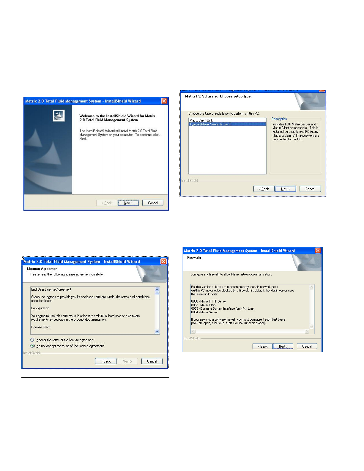
4. The setup program should start automatically. If it
doesn’t, open Windows Explorer (Start / All Pro-
grams / Accessories). Locate the CD-ROM drive
letter under My Computer and double-click the
Setup Executable File to see the screen shown in
F
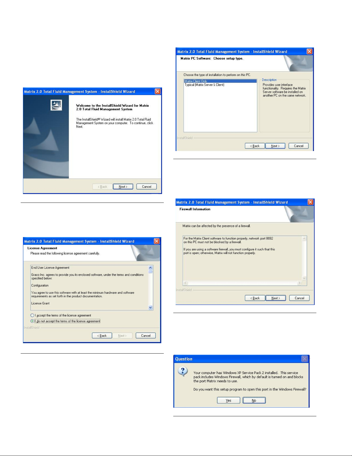
IG. 12. Click Next.
IG. 12 Setup Path 1 - InstallShield Wizard
F
5. Review the End User License Agreement (FIG. 13).
If acceptable, select “I accept…” and click Next.
6. The default setup type is shown selected: Typical
(Matrix Server & Client) (F
IG. 14). Chose this setup
type for either standalone Matrix PCs or for the
Matrix Server in multiple-PC applications. Click
Next.
FIG. 14 Setup Path 1 - Choose Setup Type
7. Note firewall configuration settings that may need to
be changed for Matrix to function (F
IG. 15). Click
Next.
F
IG. 15 Setup Path 1 - Firewalls
F
IG. 13 Setup Path 1 - License Agreement
10 312353B
Page 11
Installation Instructions
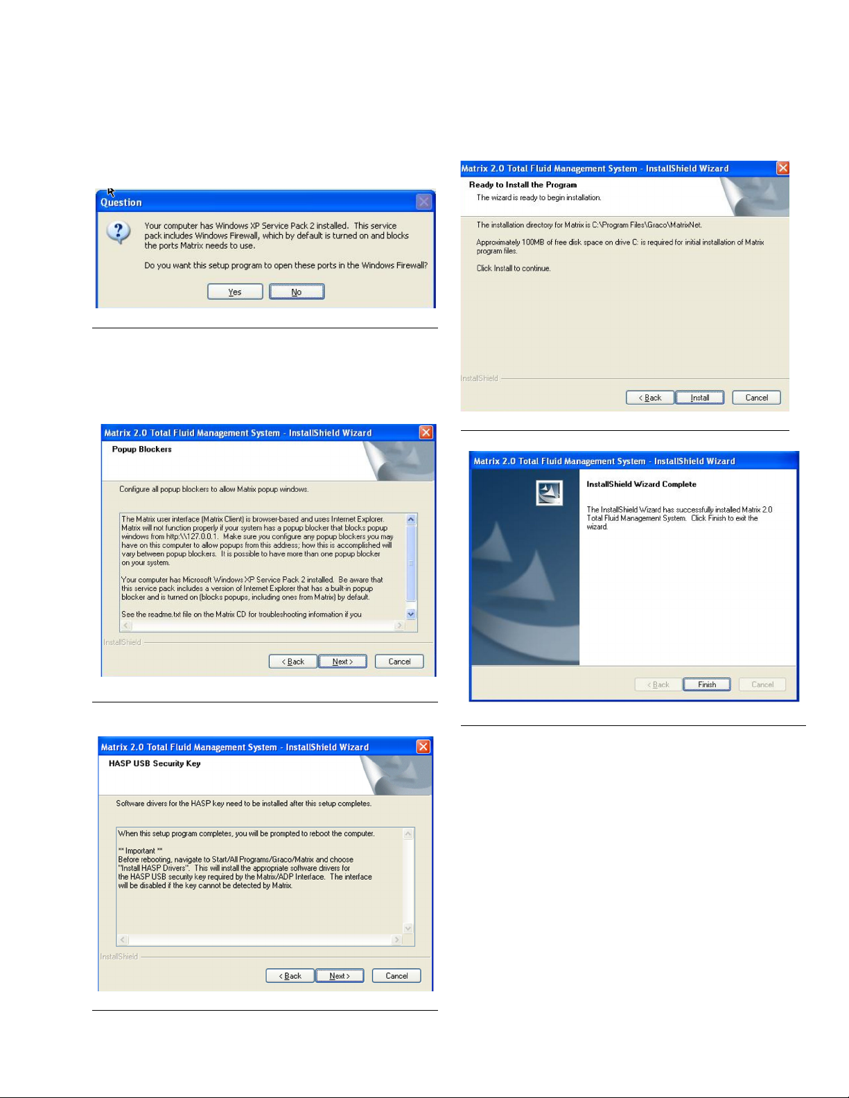
8. Setup checks for Windows XP Service Pack 2
installation. If Service Pack 2 is present, the pop-up
shown in F
IG. 16 appears. Choose Yes or No to
continue.
F
IG. 16 Setup Path 1 - Firewall Question
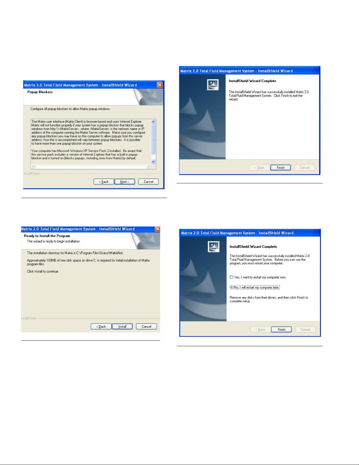
9. You may need to make changes to pop-up blockers
installed on the PC for Matrix to function properly.
Read this information carefully for guidance
(F
IG. 17). Click Next.
10. Setup is ready to install Matrix application files (F
19). Click Install.
FIG. 19 Setup Path 1 - Ready to Install
IG.
IG. 17 Setup Path 1 - Pop-up Blockers
F
F
IG. 20 Setup Path 1 - Install Complete
IG. 18 HASP USP Security Key Install Screen
F
312353B 11
Page 12
Installation Instructions
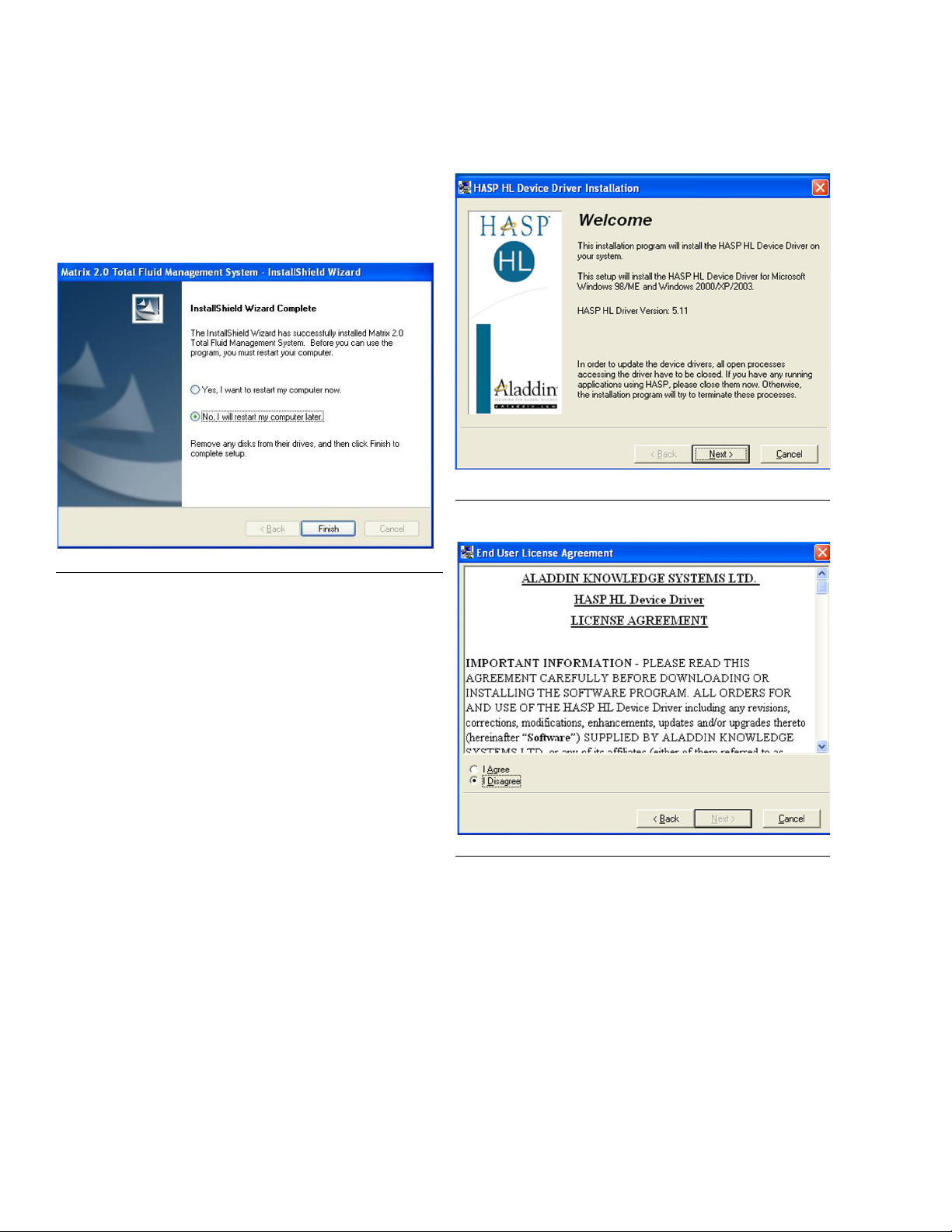
11. Matrix software installation is almost complete.
Before restarting your computer, the software drivers for the HASP key need to be installed and several configuration settings need to be checked
and/or set. Select “No, I will restart my computer
later”. Click Finish.
FIG. 21
HASP Key Driver Setup Program
FIG. 22 HASP Setup Welcome Screen
12. Install the HASP key driver (see HASP Key Driver
Setup Program section (below).
13. Review the Sun Java Runtime section on page 17.
14. Confirm that Windows on the Matrix Server PC is
not configured to hibernate after a period of inactivity (page 19).
15. Shut down the PC.
16. Plug the HASP key into an available USB port.
Since the key must be plugged in at all times for
Matrix to function properly, it is recommended that
a port out of the way (such as on the back of the
machine) be selected.
17. Restart the computer.
F
IG. 23 HASP License Agreement
12 312353B
Page 13
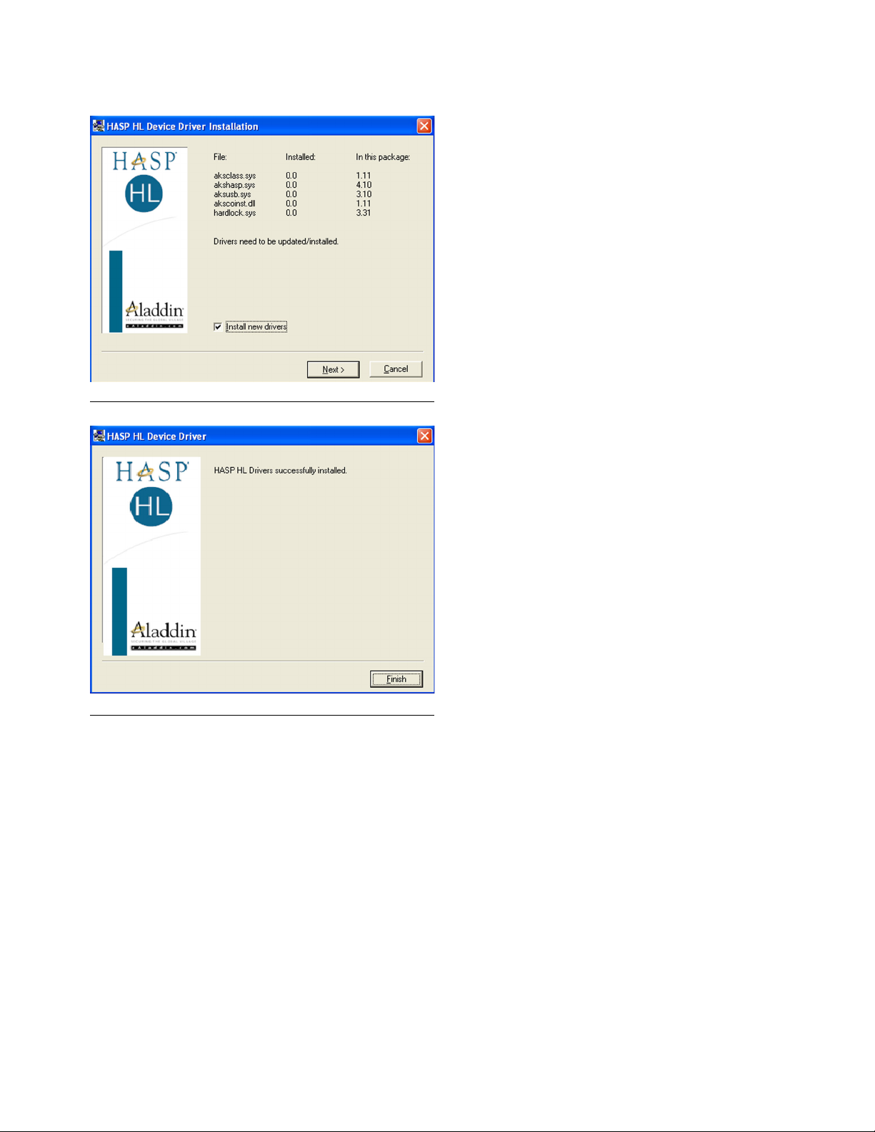
F
IG. 24 HASP Driver Files
Installation Instructions
• Matrix Reporter - accessible to Matrix system
administrators, Matrix Reporter generates system
reports on production and configuration data. Matrix
Reporter is used any time a Matrix report needs to
be generated, as well as to generate a database
backup file.
• Edit Matrix Server Network Settings - a graphical
editing tool used to configure network settings used
by the Matrix Server. Typically used only once when commissioning the Matrix system. In most
cases the default server settings will not need to be
edited.See Appendix A, page 71 and Matrix Client
PC Setup, page 36 for details.
• Edit Matrix Client Network Settings - a graphical
editing tool used to configure network settings used
by the Matrix Client. Typically used only once - when
commissioning the Matrix system. See Appendix A,
page 71 and Matrix Client PC Setup, page 36 for
details.
• End user license agreement (EULA).
F
IG. 25 HASP Setup Complete
Matrix Server and Client Shortcuts
The Typical (Matrix Server and Client) setup creates
the following shortcuts.
In Start / All Programs / Graco / Matrix:
• Matrix Server - launches the Matrix Server which
handles all RF communication to meters, tank level
monitors, database storage of dispense data and
system configuration and generates system warnings and e-mails. Matrix Server must be running at
all times.
• Install HASP Drivers - this is a shortcut to the
setup program for the software drivers required for
Matrix and Windows XP to communicate with the
HASP key. This needs to be run one time only,
immediately after installing Matrix software.
In Start / All Programs / Startup:
• Matrix Server
• Matrix Client
On the Windows Desktop:
• Matrix Client
Setup Path 2 - Matrix Client Only
FIG. 26 through FIG. 34.
1. Log into Windows XP as administrator.
2. Configure IE according to the Browser Configuration
section.
3. Insert the Matrix CD in the CD-ROM drive.
• Matrix Client - provides the IE browser-based
graphical user interface and accompanying screens.
Matrix Client must be running to access Matrix
Screens.
312353B 13
Page 14
4. The setup program should start automatically. If it
doesn’t, open Windows Explorer (Start / All Pro-
grams / Accessories). Locate the CD-ROM drive
letter under My Computer and double-click the
Setup Executable File. Click Next (F
IG. 26).
Installation Instructions
FIG. 28 Setup Path 2 - Choose Setup Type
7. Note firewall configuration settings that may need to
be changed for Matrix to function (F
IG. 29). Click
Next.
F
IG. 26 Setup Path 1 - InstallShield Wizard
5. Review the End User License Agreement (F
IG. 27).
If acceptable, select “I accept…” and click Next.
F
IG. 27 Setup Path 2 - License Agreement
6. The setup type shown selected is Matrix Client
Only (F
IG. 28), used for all machines except the
Matrix Server in multiple-PC Matrix systems. Click
Next.
F
IG. 29 Setup Path 2 - Firewall Information
8. Setup checks for Windows XP Service Pack 2
installation. If Service Pack 2 is present, the pop-up
shown in F
IG. 30 appears. Choose Yes or No to
continue.
F
IG. 30 Setup Path 2 - Firewall Question
14 312353B
Page 15
Installation Instructions
9. You may need to make changes to pop-up blockers
installed on the PC for Matrix to function properly.
Read this information carefully for guidance (F
IG.
31). Click Next.
F
IG. 31 Setup Path 2 - Pop-up Blockers
10. .Setup is ready to install Matrix application files (F
IG.
32). Click Install.
11. Transfer of application files from the setup program
to the hard disk is complete (F
IG. 33). Click Finish.
FIG. 33 Setup Path 2 - Install Complete
12. Matrix software installation is complete, however,
there are several configuration settings to check
and/or set. Select “No, I will restart my computer
later” (F
IG. 34). Click Finish.
IG. 32 Setup Path 2 - Ready to Install
F
F
IG. 34 Setup Path 2 - Setup Complete
13. Review the Sun Java Runtime section on page 17.
Confirm the settings related to the Java Plugin are
OK on this machine.
14. Follow the instructions for configuring the client PC
to communicate with the Matrix Server in the Matrix
Client PC Setup beginning on page 36.
15. Reboot the PC when complete.
312353B 15
Page 16

Installation Instructions
Matrix Client Only Shortcuts
The Matrix Client Only setup creates the following
shortcuts.
In Start / All Programs / Graco / Matrix:
• Matrix Client - provides the IE browser-based
graphical user interface and accompanying screens.
Matrix Client must be running to access Matrix
Screens.
• Matrix Reporter - accessible to Matrix system
administrators, Matrix Reporter generates system
reports on production and configuration data. Matrix
Reporter is used any time a Matrix report needs to
be generated, as well as to generate a database
backup file.
• Edit Matrix Client Network Settings - a graphical
editing tool used to configure network settings used
by the Matrix Client. Typically used only once - when
commissioning the Matrix system. See Appendix A,
page 71 and Matrix Client PC Setup, page 36 for
details.
• End user license agreement (EULA).
In Start / All Programs / Startup:
• Matrix Server
• Matrix Client
On the Windows Desktop:
• Matrix Client
16 312353B
Page 17
Installation Instructions
Sun Java Runtime
Because the startup program places shortcuts to Matrix
in the Windows Startup folder, Matrix will launch automatically when the you log into Windows. Each time
Matrix is launched, it checks for the presence of the Sun
Java Runtime Environment (JRE) on the PC. If it is not
found, Matrix will launch the setup program for it (JRE
version 1.4.2_04 is bundled with the Matrix setup) and
then exit. You must be logged into Windows XP with
administrator privileges for the JRE installation to succeed. Proceed through the JRE installation. When
installation is complete, reboot your computer. When
logged back into Windows, Graco strongly recom-
mends the following Java Plug-in configuration
changes:
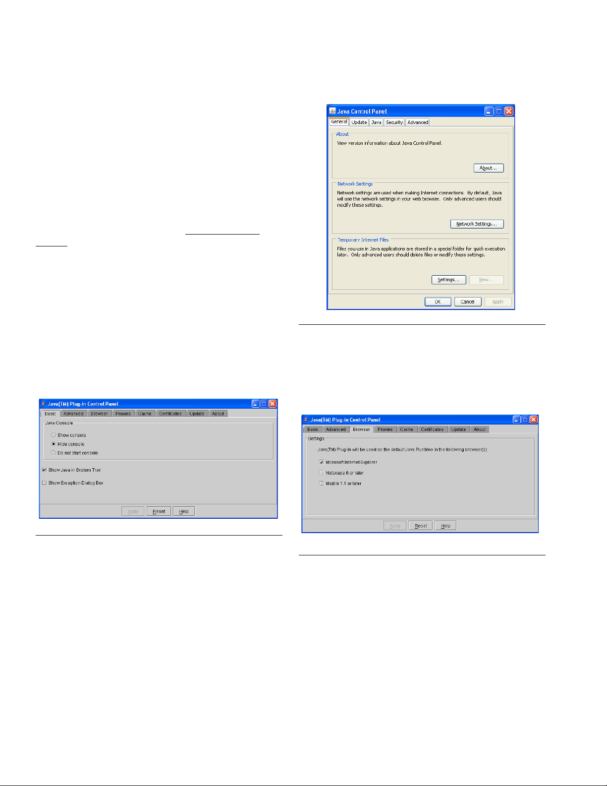
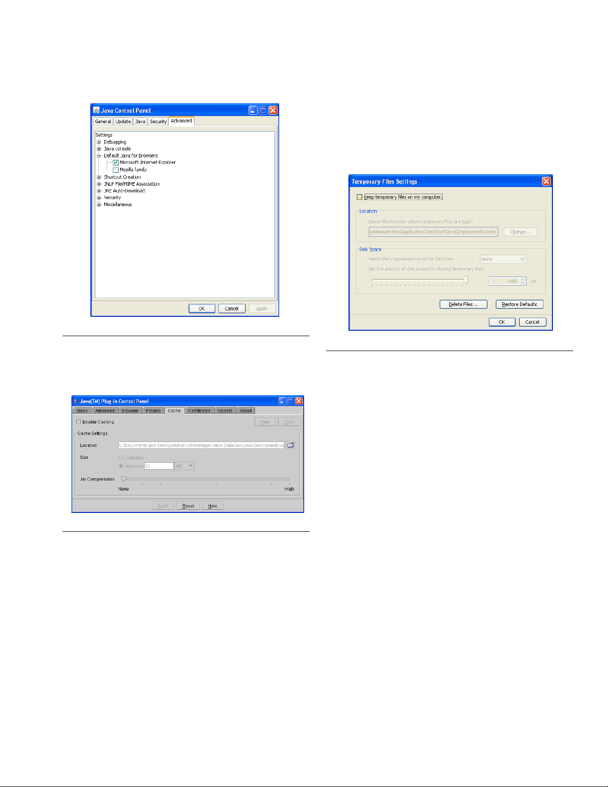
The Sun Java Plug-in must be configured to function
with the Internet Explorer browser. Graco recommends
that the Plug-in be configured to not cache Java applets.
Depending on what version of the Java Plug-in is
installed on the PC, the configuration pages for it will differ. In any case, to access the Java Plug-in Control
Panel, navigate to the Windows Control Panel and double-click the Java (Coffee Cup) Icon.
The older Plug-in looks like F
IG. 35.
The newer Plug-in looks like F
IG. 36.
FIG. 36
• Configure the Plug-in for use with Internet Explorer.
Ensure that the checkbox next to “Microsoft Internet
Explorer” is checked.
The older Java Plug-in looks like F
IG. 37.
IG. 35
F
IG. 37
F
312353B 17
Page 18
Installation Instructions
The newer Java Plug-in looks like F
F
IG. 38
• Configure the Plug-in to not cache Java applets.
The older Plug-in looks like F
IG. 38.
IG. 39.
The newer Plug-in looks like F
On the General tab, click the Settings Button in the
Temporary Internet Files section. In the corresponding popup, ensure that the checkbox is labeled
“Keep temporary files on my computer” is NOT
checked.
FIG. 40
See Software Installation Troubleshooting on page if the Java applets do not display properly.
IG. 40.
F
IG. 39
Clock and Time Zone Settings
Verify that the Microsoft XP clock and time zone settings
are correct. When the time is changed by either the PC
operator or automatically by Microsoft XP (i.e. daylight
savings time automated change), the PC must be
restarted.
MatrixLogs Folder
The Matrix setup program creates a folder named
c:\MatrixLogs. Various log files generated during Matrix
operation stored in this folder, do not delete it.
18 312353B
Page 19
Installation Instructions
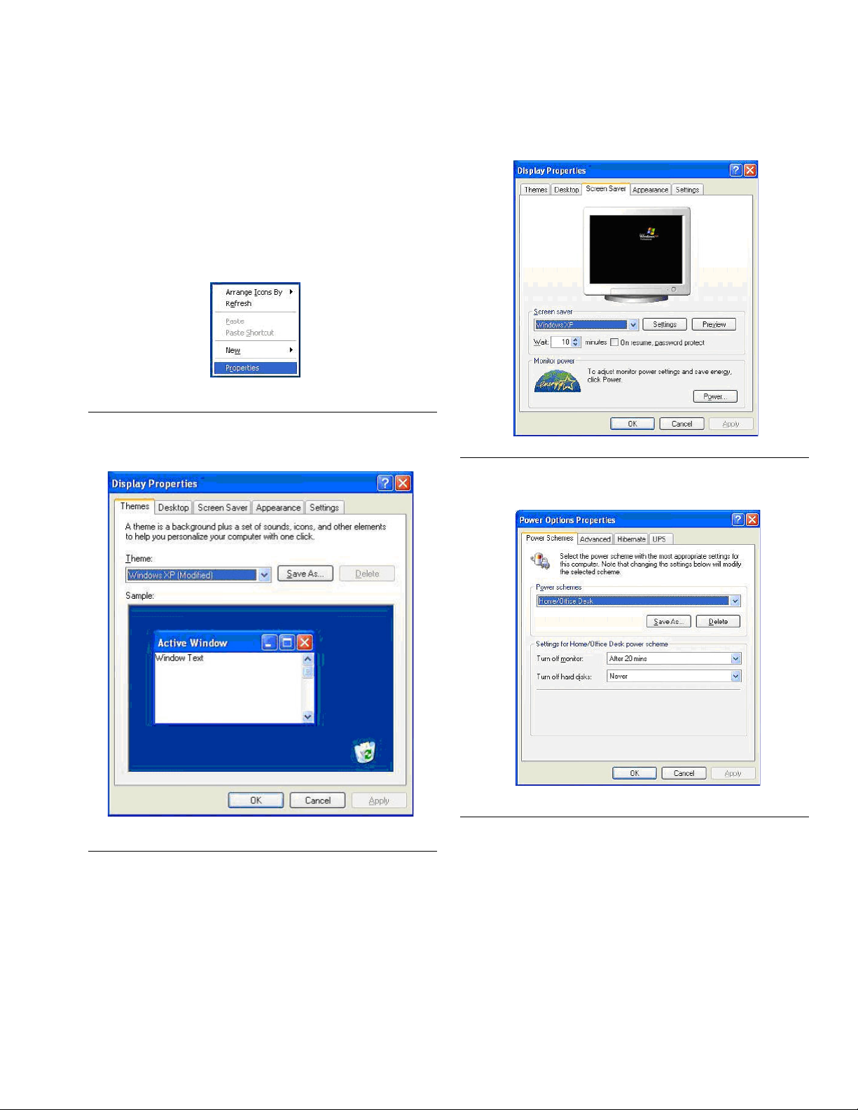
How to Turn Off Hibernation Mode in Windows XP
Ensure that Windows XP is not configured to hibernate
after a period of inactivity. If it hibernates, all meters and
tank level monitors in the system will expire a loss of RF
signal.
1. Right-click on the Desktop and choose Properties.
F
IG. 41
2. You should see a Properties window.
3. Choose the Screen Saver tab.
FIG. 43
4. Click on the Power Button.
F
IG. 44
IG. 42
F
312353B 19
Page 20
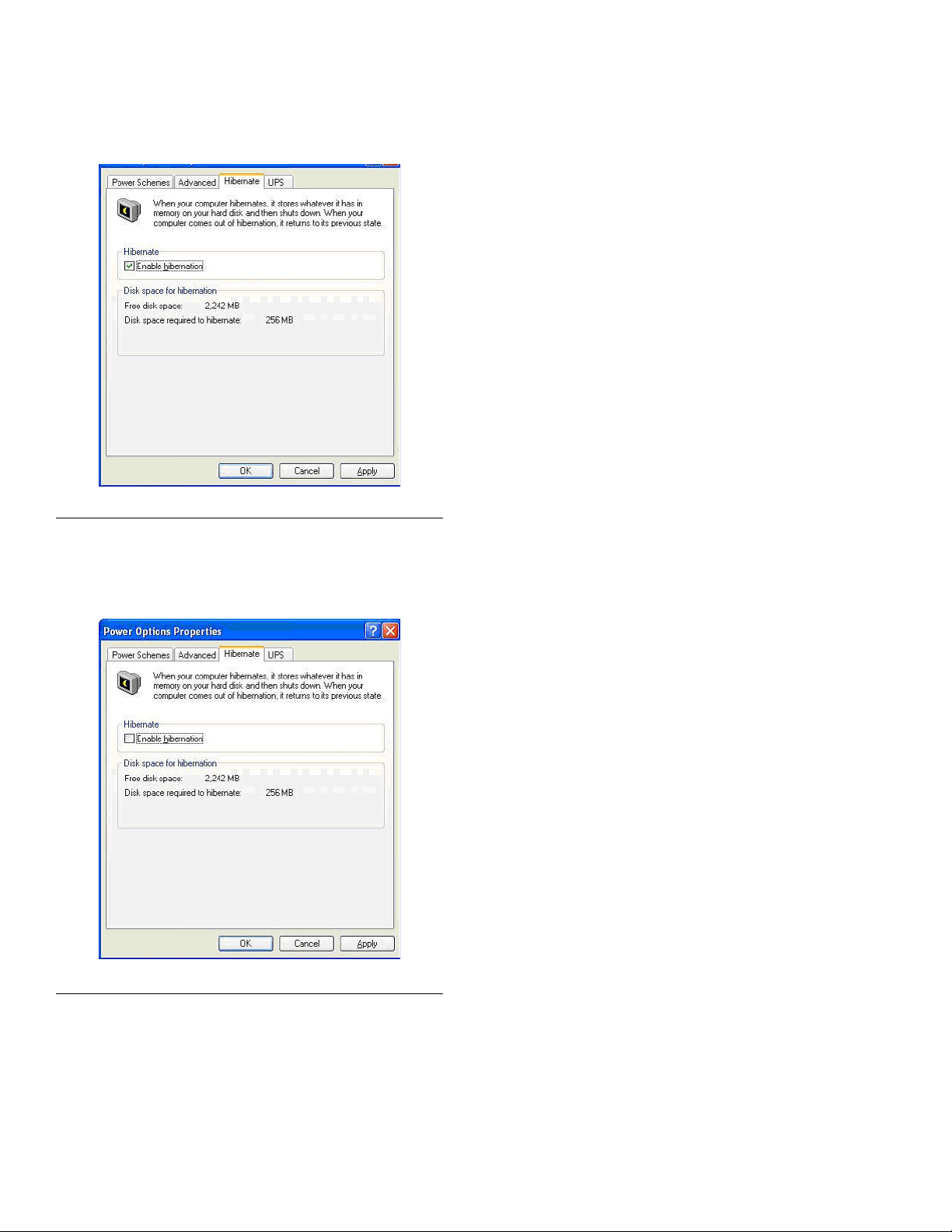
5. Click Hibernate Tab.
F
IG. 45
Installation Instructions
6. Turn off hibernation by clearing (unchecking) the
Enable hibernation check box. Click Apply and OK
to close all windows.
IG. 46
F
20 312353B
Page 21

Software Installation Troubleshooting
Problem Cause/Solution
Software Installation Troubleshooting
When Matrix is launched, I see
a progress bar for a short
period of time, but the browser
window showing the Matrix
application never appears.
At a client PC, when the Matrix
Client is launched a progress
bar appears for a long time,
finally disappears, but not
Matrix screens appear.
There may be a pop-up blocker program running on your PC and preventing
the Matrix window from opening. Verify that you do not have a pop-up blocker
integrated with your IE browser. Programs such as the Google, Yahoo, and
AOL Toolbars—among many others, including IE itself if Service Pack 2 for
Windows XP is installed—contain such features. You must configure your
pop-up blocker to not block pop-ups from the Matrix Server software. If this is
happening at the server PC, the address the pop-up blocker must allow
pop-ups from is http://127.0.0.1
pop-up blocker must allow pop-ups from http://<MatrixServer>, where
<MatrixServer> is the host name or IP address of the Matrix Server PC. How
the pop-up blocker is configured varies depending on the program, so check
that program’s documentation for instructions on how to do this. Usually, the
easiest solution is to disable the pop-up blocker entirely.
If a pop-up blocker causes the browser-based user interface to not show, the
underlying program that handles system communication, warning pop-ups,
sending e-mails, etc., should still function as normal.
A client PC cannot make a network connection to the Matrix Server. There are
numerous possible reasons for this, but the most common are:
• the host name or address of the Matrix Server as configured at the client
PC, is not correct.
• the Matrix Server has a firewall blocking port 8080.
• the client isn’t connected properly to the network.
• the network is down.
. If this is happening at a Matrix Client, the
At a client PC, when the Matrix
Client is launched, the Matrix
screens appear but the dispense history screen (or tank
level, battery level or work
order screen) shows a large
red rectangle that says something about the database not
being available.
At a client PC, the dispense
history and tank level screens
appear OK but I cannot access
the setup screens.
When Matrix is launched, I get
an error that says a connection
could not be made to the Matrix
server.
This is usually a firewall on the Matrix Server blocking port 3306. Matrix client
PCs need access to two ports on the Matrix Server, 8080 and 3306.
If the PC is designed as a Matrix shop client, this is by design. If the PC is a
primary client, make sure the name or address used in the PC client table on
the System Configuration page in the Matrix setup screens (check this on the
Matrix Server) matches exactly with the name/address given for the client in
Start / All Programs / Graco / Matrix / Edit Matrix Client Network Settings.
Make sure you do not have a software firewall blocking ports 8080-8083 or
3306 at the Matrix Server and port 8082 at each Matrix Client. Matrix must be
able to use these ports for normal operation. By default, Service Pack 2 for
Windows XP turns the built-in Windows Firewall on; ensure that these ports
are open. The system may have a firewall from another vendor, such Symantec’s Norton Internet Security, installed; this type of security software packages can contain firewalls and pop-up blockers, among other tools.
312353B 21
Page 22

Software Installation Troubleshooting
I’m sure I have no pop-up
blockers or firewalls on my
Matrix Client, but I still can’t
access the Matrix screens.
The meter dispense information screen has a white/gray
rectangle where the dispense
information should be.
After installing the JRE as
described in the installation
instructions, There is a coffee
cup icon in the system tray and
frequent pop-up windows.
What is this for, and is there a
way to turn off the pop-ups?
With Matrix installed on single
PC in a standalone system
configuration, when I launch
Matrix while my computer is not
attached to my network, the
Matrix browser-based screens
do not appear. However, if I
attach my computer to the network and launch Matrix, they
do appear.
Verify with your IT network administrator that the network has no proxy servers
that block traffic on port 8080, the default port used by Matrix for http traffic.
The meter dispense information is displayed in a table in a Java applet. Verify
that you have the Java Plugin (version 1.4.2_04 or later) installed and that it is
not disabled in IE (Tools->Internet Options->Advanced tab, the section
marked Java (Sun)).
Also, in the Windows Control Panel, you should find a Java Plug-in icon. Double-click the Icon and verify that IE is set up to use the Sun JRE for viewing
applets.
This is the Java Update mechanism that is part of the JRE, which, if enabled,
allows the JRE to make periodic automatic checks over the Internet for new
versions of the JRE. For the purpose of running Matrix this isn’t necessary. To
turn this off, go to Control Panel, double-click on the Java Plugin Icon and
choose the Update tab. Clear the Check for Updates Automatically check-
box
This happens most often with laptops that frequently connect to multiple networks using different configurations.
First, verify the proxy settings configured in your IE browser. Open a blank IE
window, click on Tools->Internet Options, and select the Connections tab.
Ensure that 1) Never dial a connection is selected, and 2) Click on LAN Set-
tings and disable automatic proxy configuration.
Also, be aware that IE, will always check for an Internet connection before
serving local web pages (see article ID 290766 on Microsoft’s online support
site, support.microsoft.com, for details).
I clicked on a Button to get to a
different page at a Matrix Client
and I got a gray screen that
says “Direct access to this
Matrix page not allowed.”
I keep getting a popup window
that says “USB security key not
found on Matrix server!
Matrix/R & R interface is disabled.” What’s going on?
Usually this means that the Matrix Server was restarted. In the Matrix system,
if the Matrix Server is restarted for any reason, all Matrix Clients must also be
restarted to reconnect to the screens. This is one reason why it’s important
that the Matrix Server be dedicated to the Matrix system.
The HASP security key shipped with this version of Matrix must be plugged
into a USB port on the Matrix Server at all times, even if the Matrix/R & R interface is disabled. This message will appear when the Matrix Server software
cannot detect the presence of the key. The key could be unplugged. The software drivers for the key may not have been installed; if this is the case, while
logged in with Windows administrative rights, navigate to Start/All Programs/Graco/Matrix and choose Install HASP Drivers. Graco recommends the
key be plugged into a USB port on the Matrix Server itself, as opposed to
being plugged into a USB hub that is in turn plugged into the Server
Make sure you reboot the Matrix Server after installing the HASP driver software.
22 312353B
Page 23

Software Installation Troubleshooting
When I enter a work order at a
meter, I get a “WO
REJECTED” message, even
though I know the work order
exists in the DMS and is open.
Why?
When a work order is sent to the PC from a meter, the PC must validate the
work order with the R & R DMS. If, for any reason, the work order cannot be
validated (the work order is closed, it has a status that doesn’t allow the addition of charges, the network between Matrix and the DMS is down, etc.), the
PC returns this message to the meter. You could try adding the work order at
the PC for better detail on why the work order isn’t being validated.
312353B 23
Page 24

Software Installation Troubleshooting
Uninstalling Matrix on Windows XP
Follow this procedure to remove Matrix software and
data files stored on your computer. You will lose all
Matrix system parameters and all Matrix dispense history using these procedures unless you first use Matrix
Reporter to make a back-up of the database by exporting it to a *.sql file.
• You must have Windows XP administrator privileges
in order to add or remove Matrix from the computer.
• Any files you have created with Matrix since it was
originally installed, such as database export files,
reports, and log files will not be removed by the
uninstall program. If you wish to also remove these
from your hard drive, you will have to do so manually
using Windows Explorer after the uninstall program
completes.
1. Choose Start / Control Panel from the Windows
Start menu.
2. In Control Panel, double-click Add or Remove Pro-
grams.
3. Scroll to Matrix in the program listing and click it
once to highlight it.
4. Click the Remove box.
5. In the dialog box that appears, choose Remove.
from the list of options and click Next.
6. Click Yes in the window that asks you to confirm
your selection.
7. The uninstall program runs.
8. Click Finish.
You may be prompted to reboot as the final step of the
uninstall process. Graco recommends that you always
reboot when you have uninstalled Matrix software.
Matrix log files found in c:\MatrixLogs, will not be
removed by the automated uninstall process. They
must be deleted manually.
24 312353B
Page 25

Operator Screens
Operator Screens
F
IG. 47 Operating Screens
Meter Dispense Information _________________________________
Position the cursor over the Meter Dispense Status box causing the text to turn yellow. Left click the Box to go to the
Meter Dispense Information screen (F
IG. 48 Meter Dispense Information Screen
F
This screen displays the complete dispense history of all
meters in the system through two tables of information.
The top table lists all the active dispenses in the system
and the bottom table displays all completed dispenses.
Active Work Orders
Date & Time - the date and time of the dispense.
Meter Name - the meter and fluid names.
Work Order - the tracking number the facility uses for
work orders (if the meter is in work order mode).
Status - the current status of the dispense.
Dispense History
IG. 48).
Meter Name - the meter and fluid names.
Amount - the exact fluid amount dispensed, with units.
Work Order - the tracking number the facility uses for
work orders (if the meter is in work order mode).
Posting Status - displays the status of the Matrix R & R
interface’s attempt to add this fluid charge to the RO on
the R & R DMS.
User Data - allows the user to add information to the
screen
Status - the final status of the dispense.
Date & Time - the date and time of the dispense.
312353B 25
Page 26

Operator Screens
Tank Level Information _____________________________________
Place the cursor over the Tank Level Information box, causing the text to turn yellow. Left click the Box to go to the
Tank Setup screen (F
F
IG. 49 Tank Level Information Screen
IG. 49).
This screen provides tank level status activity for all
tanks in the system:
Date & Time - displays the day, month, date, time, and
year that the dispense took place.
Tan k N a m e - displays each fluid storage tank in use with
the Matrix system and the numbers or labels that are
assigned to them.
Fluid Type - displays the type of fluid stored in the tank.
Tan k C a p a c i t y - displays the total gallons of fluid that the
tank is capable of holding when full.
Current Volume - displays the tank volume in gallons.
Battery - displays the amount of battery life remaining.
Tank volume, as shown in F
of several different events:
1. Tank Level Monitor reading – The current tank volume is updated by readings sent by a tank level
monitor mounted on the tank. These readings can
be both scheduled (programmed) to happen a specific times during the day; they also happen each
time the blue button on the tank level monitor is
pressed. The tank level readings sent from the tank
level monitor always overwrite whatever Matrix currently has as the current tank volume.
2. Meter dispenses – When a meter dispenses from
the tank, Matrix calculates the new current tank volume by subtracting the amount dispensed. For
every dispense from the tank, this is repeated.
3. Manual tank level adjustments – On the tank setup
screen, the adjust link there allows the user to manually increase or decrease the current tank volume.
This is commonly done for fresh oil deliveries and
waste oil removal.
IG. 49, changes as a result
26 312353B
Page 27

Operator Screens
Battery Level Information ___________________________________
Place the cursor over the Battery Level Information box, causing the text to turn yellow. Left click the Box to go to the
Battery Level Information screen (F
F
IG. 50 Battery Level Information Screen
IG. 50).
This screen provides battery charge level for all meters
and tank level monitor batteries in the system. Each row
corresponds to a meter or tank.
Date & Time - the date and time of the last battery status update
Meter Or Tank Name - the name of the meter or tank,
including the fluid name associated with it.
Warning Level - the user-configurable point at which the
battery should be replaced for the meter or tank,
expressed as a percentage of a fully charged battery
and set in the meter or tank’s setup configuration.
Battery Level Status - the actual battery status,
expressed as a percentage of a fully charged battery.
Entering Work Orders ______________________________________
Place the cursor over the Entering Work Orders box, causing the text to turn yellow. Left click the Box to go to the
Entering Work Orders Status screen (F
To access this screen, you first need to type in your user name and password when the authenticate user
screen appears. User Names and Passwords are initially set up by the System Administrator.
IG. 51).
F
IG. 51 Work Order Information Screen
This screen displays all the meters that are programmed
to be in work order mode and their respective work
orders. It is a password protected screen that allows
users to assign work orders to specific meters.
Meter Name - the meter and fluid names.
312353B 27
Status - indicates meter status when assigning work
orders.
Slot 1 through Slot 5 - displays the meter’s work order
list. Each meter has its own work order list that can contain up to 5 work orders, one per “slot” in the list.
Page 28

Operator Screens
Work Orders and the Matrix/R & R Interface
For meters configured to use the Matrix R & R Interface,
dispenses are tracked by work order. This version of
Matrix requires that work orders entered at a Matrix PC
or at a meter, be validated before fluid can be dispensed. Once the dispense is complete, the appropriate
charge for the fluid will be automatically posted (added)
to the work order (RO) in R & R.
Adding Work Order From PC
1. To add a work order, left click Add Work Order,
located in the upper left corner of the screen (F
52).
IG.
For more information on what validation and posting means, see Work Order Validation and Work
Order Posting below and on page 29.
To override validation, check the Don’t validate
RO checkbox. To override posting of charges,
check the Don’t post charges to RO checkbox.
Enter a Matrix administrator’s user name and
password. If posting charges is overridden, the
Add Parts button is disabled.
6. At this point you may click, Send To Meter or Add
Parts.
Clicking Send To Meter will submit this work order
for validation. If successfully validated, the work
order will be sent to the meter and appear in the
meter’s work order list. If the work order is not validated, a popup window similar to F
IG. 53 will
appear; you can either retry or cancel. Until the
work order is successfully validated, the work order
will not appear in the meter’s work order list.
IG. 52 Add Work Order
F
2. Select the desired meter from the drop-down box.
This is the meter that will dispense the fluid on the
work order being entered.
3. Enter a work order number, up to 12 characters.
This must exactly match the RO number in R & R.
4. Enter a numeric job code. The number entered into
this field corresponds to the job (line) on the R & R
RO to which the oil should be charged. It cannot be
left blank or not be a number. This field is where the
user tells Matrix where on the R & R RO the fluid
part must be added.
5. Matrix administrators have the ability to override
work order validation and/or posting of Matrix-generated charges to the work order.
F
IG. 53 Validation Failed
Clicking Add Parts will allow you to “attach” one or
more non-fluid parts to this work order on a screen
that looks like F
IG. 54 Add Parts
F
IG. 54.
28 312353B
Page 29

Add Parts To Work Order
In the drop down list at the top left, select the category of
parts you wish to choose from; the parts loaded into
Matrix in that category (appear in the list box on the left.
Click Add>> to select the part. Selected parts appear in
the list box on the right. Clicking the Clear All button
removes the entire list of selected parts. Individual parts
can be removed from the selected list by selecting the
part and pressing Remove Part.
When finished adding parts, click Send To Meter, which
submits this work order for validation. If successfully validated, the work order is then sent to the meter and will
appear in the meter’s work order list. The list of selected
parts are not physically sent anywhere; Matrix “remembers” the selected parts list for this work order until the
fluid has been dispensed and successfully posted to the
RO in R & R; once this has happened, the selected
parts list is also posted to the RO.
Work Order Validation
Operator Screens
F
IG. 55
Work Order Posting
Matrix does not add any parts or other charges to a
work order (RO) on the R & R DMS until the Matrix system has dispensed fluid against that work order. Upon
completing a fluid dispense, Matrix will do the following:
A work order is considered “validated” if within the R & R
DMS it meets these criteria:
1. The work order exists, including the user-entered
job number on that work order.
2. The work order is open and is not currently being
edited. Matrix cannot post charges to work orders
that have been closed.
3. The status of the work order must be such that additional parts/charges can be added to the work order.
Depending on the activity level of the network and the R
& R DMS, the time it takes to validate a work order can
range from a few seconds to 30 seconds.
If the work order is not validated, a message similar to
F
IG. 55 will appear, stating the reason why it could not
be validated. Right click on the work order to try validating it again or correct the core problem (e.g., if someone
has the work order open and is editing it, retry again
when they are out of it).
1. Record the amount dispensed in the meter dispense history.
2. Based on the unit and measure pricing configuration
for the fluid dispensed, the appropriate part or GOG
charge is determined.
3. The part of GOG charge is sent to the DMS for that
work order. See “Interface Behavior, Parts and
GOG” on page 52 and Table 1 on page 53 for more
details
If a posting is successful, the Dispense History will
appear similar to the one shown in F
IG. 56. To view
more detailed posting status, right-click on the Work
Order Record and select View Posting Details
(F
IG. 56). Additional posting details will appear in a
popup screen (F
IG. 57). This information is also
available in report format using Matrix Reporter.
312353B 29
Page 30

Operator Screens
Sending a Work Order to a Meter
If the PC cannot send a work order to the chosen meter
for any reason, a Retry/Cancel pop-up box, as shown in
F
IG. 61, will be displayed. Clicking Retry will make the
PC attempt to send the work order again. Clicking Can-
cel will do just that, effectively deleting the work order at
the PC; no more retries will be attempted.
There are several system conditions that can cause this
to happen:
1. The battery in the meter is very low or dead. With a
dead battery, the meter cannot communicate to the
PC. Replace the battery with a fully charged battery.
2. The meter is already in the process of accepting a
work order (possibly from another Matrix PC). Wait
ten seconds and try sending it again.
F
IG. 56
F
IG. 57
If you are editing the RO while Matrix is attempting to
add parts to it, the Matrix posting attempt will fail, since
an R & R RO can only be edited by one person at any
time.
In Matrix, when any posting error occurs, the record
associated with this work order will turn red in the meter
dispense history and Matrix will generate a popup windows explaining the problem. You can manually retry the
posting or cancel by right-clicking on the Work Order in
the Meter Dispense History and selecting Retry Posting Charges.
3. A poor RF signal between transceiver and meter
can cause the work order to not be successfully
delivered to the meter. You may need to move the
transceiver closer to the meter.
4. A meter cannot accept work orders while it is dispensing fluid. It is unlikely that the meter and PC will
get out of synch for this to happen. At the meter, end
the dispense; the meter’s end-of-dispense message
to the PC will cause the two to get back in synch.
Work Order Pop-up Windows
The system is not always able to send new work
orders from the PC. If this is the case, one of the following pop-up windows will appear to inform you
that the work order was not received by the meter.
1. Work Order Limit (F
when the PC has five open work orders associated
with the meter being addressed. No RF communication is attempted when this message appears. At
least one work order will need to be processed or
removed before a new one can be loaded.
IG. 58). This message appears
If no fluid was dispensed (dispense volume is 0), Matrix
will not attempt to post charges of any kind to an R & R
RO.
FIG. 58 Work Order Limit
2. Work Order Already In Process (F
IG. 59). This
message appears when the PC is attempting to
send another work order. No RF communication is
30 312353B
Page 31

attempted when this screen appears. Attempt to
send the work order again.
F
IG. 59 Work Order Already in Process
Operator Screens
3. Meter is Busy (F
IG. 60). This message appears
when the PC has received an Activate message
from the meter being addressed. No RF communication is attempted when this screen appears.
Attempt to send the work order again when the
meter has completed processing the active work
order.
F
IG. 60 Meter Is Busy
4. Couldn’t Send Work Order (F
IG. 61). This mes-
sage appears when the PC tries to communicate
with the meter and receives no response. RF communication is attempted when this screen appears.
This message indicates the battery in the meter is
removed or needs to be recharged, the transceiver
is unplugged, or the RF environment has changed.
Correct these conditions and attempt to send the
work order again.
F
IG. 61 Couldn’t Send Work Order
312353B 31
Page 32

System Administrator Screens
System Administrator Screens
Matrix System Setup
Once the Matrix PC software is installed, it’s necessary
to synchronize the software with the other hardware
components of the Matrix system. This is done through
the system administrator portion of the software. This
section is password protected and provides access to all
Matrix setup screens. Only individuals with system
administrator rights have access to this portion of the
program.
Move the mouse pointer to the box labeled Matrix System Setup. The text will turn yellow. Left click to bring up
the Authenticate User Dialogue Box.
1. Key in your user information and click Submit. For
initial log on only, type in matrix (lowercase) for user
name and graco (lowercase) for the password.
Click Submit. Once the initial log on information is
authenticated, the System Administration screen
appears (F
Personalized passwords for System Administration, Entering Work Orders, and for Adjusting Tank
Levels are entered at the System User Setup
screen, see page 38. Once a new admin user
account is created, the default matrix/graco
account is disabled.
IG. 62).
The system administrator has access to:
• System Configuration - setting global security, measurement system, Transceiver configuration and
Matrix PC client information.
• System User Setup - add, modify, and remove
users, set security level and PIN information.
• Ta n k S e t u p - add, modify, adjust, remove, and program tank level monitors.
• Meter Setup - add, remove, modify, and program
meters.
• E-mail Setup - configure email to be sent to responsible parties based on various tank conditions.
• R & R Interface Setup - Configure the Matrix/R&R
interface.
• Return to Operating Screens- returns the user to the
operating screens.
F
IG. 62 System Administration Screen
32 312353B
Page 33

System Administrator Screens
System Configuration ______________________________________
There are three sections of the System Configuration screen: General system-wide default settings, transceiver settings, and PC client settings (F
The System Configuration setup must be performed prior to defining all other Matrix system setup parame-
ters.
IG. 63).
F
IG. 63 System Configuration Screen
To change any of the settings listed for system configuration, click Modify.
Security Level (Global Setting)
The security level is the global security setting for all
meters in the system, The default is System Monitoring.
PIN code and Parts Room Authorization Security are
other options on the pull down menu. This security
choice can be changed on a meter-to-meter basis if
desired (F
1. Click Security Level Drop Down Box and select
• System Monitoring - anyone can dispense oil, but
• PIN Code Required - the operator must enter a
IG. 64).
from the list.
the dispense information will be communicated to
the PC.
user-specific 4-digit numeric code into the meter to
have authorization to dispense.
System Emergency Code (FIG. 64)
The System Emergency Code is used to bypass PIN
Code or Parts Room Authorization security features
should the communication link to the Matrix PC stop (i.e.
computer failure, power outage).
2. Type in a four digit system emergency code number.
This number is used at the meter to override all meter
programming should there be a loss of RF signal.
This allows the operator to continue dispensing fluids
even though the meter is not receiving an RF signal.
If the system emergency code is used to override the meter program, the meter must be programmed again using the Matrix PC software
once the RF signal has been restored.
• Parts Room Authorization - the operator selects
authorization to dispense at the meter. This requires
someone in the Parts Room to authorize the dispense at the Matrix PC.
312353B 33
Page 34

System Administrator Screens
Unit of Measure (English or Metric) (FIG. 64)
Measurement System is the global units of measurement setting. English and Metric are the two options in
the pull down menu. This setting can be changed on a
tank-to-tank and meter-to-meter basis.
1. In the Measurement System box, select English or
Metric.
2. Click Apply.
Edit Contact Information (FIG. 64)
The Edit Contact Information dialog box appears once
apply is selected. Fill in the appropriate fields. This information will be placed automatically on all outgoing
Matrix e-mail (F
IG. 65).
IG. 64 Select Settings Below
F
FIG. 65 Edit Contact Information
Click Apply to update contact information and return to
the System Configuration screen.
34 312353B
Page 35

System Administrator Screens
Transceiver Setup
Click Add Transceiver Button, then click Modify.
1. Enter the area of the shop where the transceiver is
located (i.e., Main Shop, Fast Lube Shop, Engine
Department) in the Transceiver Name field.
2. The Network ID is a letter designation for the Transceiver network identification. The default is (A).
There are eight network ID’s available designated
with the letters A through H. Type in the selected
Network ID.
The Network ID letter for a given Transceiver
must match that Transceiver’s dipswitch settings.
3. Transceiver ID is a letter designation for the Transceiver Identification. The default is (A). There are
eight Transceiver ID’s available designated with the
letters A through H.
The Transceiver ID letter for a given Transceiver
must match that Transceivers equivalent dipswitch settings.
Confirm PC/Transceiver Communication
Each time a transceiver is powered up, it reads its dip
switch settings for Network ID and Transceiver ID and
sends this information to the PC. It also sends the transceiver’s firmware revision level. These settings are displayed as “Last Power-up Settings” and “Firmware
Revision” on this screen. If these fields are “N/A”, it
means that the transceiver has never (successfully)
communicated with the PC.
One way to confirm that the serial connection between
PC and transceiver is functioning properly is to change
the transceiver dip switch settings and verify that the PC
software reflects the new settings. Refer to the transceiver manual on how to set transceiver dip switches.
Example:
A Matrix system has a single transceiver, the desired
settings on the transceiver setup screen (F
Network ID = A, Transceiver ID = A, and Serial Port =
COM1 (factory defaults).
IG. 66) are
4. Serial Port is a pull down menu of all available communication ports on the Matrix PC. COM 1 is the
default setting. If COM 1 is not available, select an
open port from the pull down list.
Some computers may not have any serial ports.
In this case a USB converter will be required to
obtain serial ports. Graco recommends Edgeport models from B & B Electronics.
If you attempt to add a Transceiver and the PC
has no COM ports available, an error message
appears. Contact your IT professional or add
serial ports using the USB convertors recommended by Graco. See page 4 for additional
information.
Firmware Revision is the Transceiver firmware
revision level.
Transceiver Power-up
Graco recommends that when you plug in the power
cord to the transceiver, do it with the PC serial cable
already plugged in.
FIG. 66
1. If it’s open, close the transceiver setup screen (F
66).
2. Power off the transceiver.
3. Set the transceiver dipswitch settings to:
Network ID = H
Transceiver ID = H
Refer to transceiver manual 309498 for instructions.
4. With one end of the serial cable already plugged
into the PC and the other end in the transceiver,
power up the transceiver.
IG.
312353B 35
Page 36

System Administrator Screens
5. As the transceiver initializes itself on power-up,
watch the LED lights on the side of the transceiver.
You should see the lights flicker briefly with a burst
of activity. You may see occasional flickering of the
lights after this initial burst.
6. After the brief burst of LED activity, open the transceiver setup screen in the PC software and check
the “Last Power-up Settings”. If they show the Network ID = H and Transceiver ID = H settings as
described above, the serial connection between the
PC and the transceiver is functioning properly.
7. Close the transceiver setup screen.
8. Power down the transceiver and restore the dip
switch settings to their Network ID = A, Transceiver
ID = A settings.
9. Power up the transceiver.
10. After the initialization activity reflected by the lights
on the transceiver, open the transceiver setup
screen and confirm that the “Last Power-up Settings” read Network ID = A and Transceiver ID = A.
If the “Last Power-up Settings” do not update, one or
more things may be happening.
First, the serial port selected on the transceiver setup
screen may not be the one the serial cable is plugged
into. Many newer computers have only one serial port
on the back of the computer; the port may or may not be
COM1. It could easily be another COM number, so if
other COM ports show up in the transceiver setup
screen’s drop down list for Serial Port selection, try
using each of those in turn and repeat the above steps.
Many new computers have no serial ports at all, in which
case a USB to RS232 converter is required to supply at
least one serial port. Graco recommends the purchase
of Edgeport brand USB to RS232 converters, available
from www.bb-elec.com
tions for the converter carefully and make sure you
reboot the computer when complete. Again, don’t
assume the COM port number—the documentation with
the converter should help explain what COM port number the converter will provide.
When the Matrix PC software starts up, one of the first
things it does is check with Windows to find out what
serial ports (COM ports) exist in the system. These
ports are the ones listed in the Serial Port drop down list
on the transceiver setup screen. If a port you expect is
not listed there, it is because it is not registered as a
valid port with Windows.
. Follow the installation instruc-
Second, the selected COM port may be in use by
another program on the PC. In this case, even if the
Serial Port selection on the transceiver setup screen
matches the port the cable is plugged into, no Matrix
communication will happen because a different software
program “owns” the port. The only way to get it to work
is to either shut down the other program or configure
either the other program or Matrix to use a different
COM port. Software programs that use serial ports
include fax software and PDA software.
Third, the cable between the PC and the transceiver
could be either bad or wired improperly. The latter is
most likely to occur when an RS422 connection is used;
the former could happen with either serial cable choice.
Make sure the cables are firmly connected, so that there
isn’t a chance the plug or wire is falling out on either
end.
Repeat this setup for each Transceiver ensuring that no
two Transceivers use the same Network and Transceiver
IDs. If you have only one transceiver, Graco recommends using the default Network ID and Transceiver ID
settings.
Matrix Client PC Setup
The lower portion of the System Configuration page is
used to register a networked PC client in the Matrix system. Without registration here, a client PC will have limited functionality (such as not being able to submit work
orders to meters or viewing system-wide alerts/errors)
even though many of the screens will still be viewable
from the client.
Note that by default, the PC client table on this page has
one entry; this entry corresponds to the Matrix Server
and always must be present. Graco recommends you
not change this entry’s name/address field from
127.0.0.1, nor the port number from 8082 unless there
are known port conflicts.
Every PC client in the Matrix system is either a “shop client” or a “primary client”. Exactly one PC in the system
can be the primary client. Both types can view the
Matrix screens and run reports, but only primary clients
can access the Matrix setup screens and display system-wide alerts/error messages. The Matrix Server can
always access the setup screens, regardless of the client type it is set to.
36 312353B
Page 37

System Administrator Screens
Add a Client PC to the Matrix System
At the Matrix Server PC (FIG. 67):
1. Click Add Pc Client Button; this adds a new row to
the bottom of the table.
2. Click New Row’s Modify Link.
3. In the PC Client field, enter the host name or IP
address of the client PC (remember this name or
address; it will be needed when configuring the
Matrix software at the client PC).
4. Enter an appropriate description for this PC in the
Description field and select its Client Type. Click
Apply.
2. When the installation is complete, the installation
program prompts you to reboot the PC. Before
doing so, navigate in Windows to Start / All Pro-
grams / Graco / Matrix / Edit Matrix Client Network Settings.
3. Set the Matrix Client Host Name to the client PC’s
actual host name or IP address.
• Do not set this to 127.0.0.1.
• This entry must match exactly with the
name/address give for this PC in the PC client
table on the System Configuration page in the
Matrix setup screens (F
IG. 68).
4. Set the Matrix Server Host Name to the Matrix
Server’s actual host name or IP address.
• Do not set this to 127.0.0.1.
5. Unless there are known conflicts with the port numbers, they can be left at the factory defaults.
6. Click Save and exit.
F
IG. 67
At the client PC (
FIG. 68):
1. Run the installation program from the Matrix installation cd, choosing Matrix Client Only as the installation type.
7. Reboot the client PC.
See the Software Installation Troubleshooting section on
page 21.
FIG. 68
312353B 37
Page 38

System Administrator Screens
System User Setup ________________________________________
Click System User Setup to go to the Systems User Setup screen (FIG. 69). Use this screen to add new users, new system administrators, as well as to set user security PIN numbers.
F
IG. 69 Systems User Setup Screen
Click System User Setup, then Modify for each person
that will use the Matrix system at the PC or at a meter.
Adding a New User
For each new user, click ADD SYSTEM USER. This
adds a new row to the bottom of the user list. See Mod-
ify User Settings for configuring each user profile.
Modify User Profile (FIG. 70)
Click Modify Link for the user whose profile is to be
edited/changed.
in for each access to work orders and system setup
screens.
2. Pin Number – a system-wide unique 4-digit number
between 0000 and 9999. If a meter is configured to
use PIN codes, this is the number that allows
access to dispense fluid from the meter.
3. Security Level – can be one of three possible settings:
a. Basic – can monitor Matrix status screens and
operate meters.
b. Wor k Orders – allows all Basic privileges, plus
allows work order entry at the PC.
c. Administrator – has complete access to all
components of the software.
4. Click Apply.
5. The user password window is displayed (F
This password is used with the user name to access
the work order screen (for users who have Work
Order security level or higher) and setup screens
(for Administrators). Choose a short password, but
one that cannot be easily guessed (not found in a
dictionary, for example).
IG. 71).
FIG. 70 Select Settings Below
1. User Name – a system-wide unique user name. If
the user will have Work Orders or Administrator
security level, it is convenient to have a short, easily
remembered user name, since it needs to be typed
38 312353B
FIG. 71
Page 39

System Administrator Screens
More than one user can have Administrator security
access. However, as soon as one administrator user is
created, the default matrix/graco user name and password will be disabled. Users with Administrator security
level have special responsibility to keep track of their
user name and password, as well as keep it secure.
If you misplace your system administrator password, call
the Graco Lubrication Equipment Support Team at
1-900-533-9655 from 7:30am to 5:00pm CST.
Changing User Information.
1. Select the user information to change and click
Modify.
2. Select and change the information.
3. Click Apply to update the record.
Removing a User
In the Action Column of the user record, click Remove
to remove the user record from the System Users Setup
screen.
Tank Setup _______________________________________________
Click Tank Set up to go to the Tank Setup screen (FIG. 72). Tanks must be configured before meters can be configured.
F
IG. 72 Tank Setup Screen
Customized Fluid Setup
To add, edit, or remove a fluid from the Tank setup, click
Customized Fluid List Button located in the upper left
corner of the Tank Setup screen (F
Setup dialogue box appears (F
To Add a new fluid to the entry list
Click Add. Type in the new fluid name and a description,
and select the type of fluid from the drop down box. Click
Add to add a fluid to the list. You will need to provide a
fluid name, description, and select if it’s Oil/ATF, Gear
Lube, or Anti-Freeze 50/50. For ease of reading elsewhere in the program and in the reports, a short name is
recommended. Click Apply to update the record.
To Remove a fluid
Select the fluid to remove, and click Remove. The
record is deleted from the list and you return to the Tank
Setup screen.
IG. 72). The Fluid
IG. 73.
FIG. 73 Select a Fluid Entry to Add or Remove
312353B 39
Page 40

System Administrator Screens
Adding a New Tank using a TLM
1. Click Add Tank. A new blank record is added. Ta nk s
must be setup and programmed prior to meters
being setup (F
2. Select modify for the newly added tank
3. Tank Name : select and name the tank
.
This field is alpha/numeric. For 1 - 99 TLMs use
the following numbering 01, 02, 03, … 09. For 100
- 999 TLMs use the following numbering 001, 002,
003, … 010, 011, 012. This ensures the tanks will
be listed in the correct sequence in the Matrix system. To avoid issues with the reporting function, do
not use commas in data fields.
IG. 74).
4. Fluid Name: select any type of service fluid from
the drop down list.
5. Tank Capacity: fill in the tank capacity and select a
measurement (i.e. 500 gallons).
Vertical wall tanks use this capacity figure to calculate tank volume. Make certain the value is accurate. The tanks of other shapes calculate capacity
based on user-entered dimensions.
6. Tank Level Monitor: select yes if you plan to use a
Tank Level Monitor (TLM) on the tank and No if you
don’t plan to use one. If yes, you will be prompted
for additional information about this tank.
7. Tank Shape: select either vertical walls, cylinder, or
obround. See page 41 for information regarding
tank shape.
8. Tank Warning Level: default is 10%, but can be
changed as required. The monitor will send a low or
high tank level warning screen to the PC when the
tank level reaches 10% capacity, alerting the System Administrator that the tank level is low and
needs more fluid or high and must be evacuated.
F
IG. 74 Edit Tank Setup
9. Tank Warning Type: the Low setting is for new ser-
vice fluids and the High setting is for used oil tanks.
40 312353B
Page 41

Tank Shape Screen
Vertical Tank Geometry (FIG. 75)
Vertical tanks use the tank capacity to calculate tank volume. Obround and cylindrical tanks use the tank dimen-
sions to calculate tank volume.
Vertical Tank
System Administrator Screens
Obround Tank
IG. 75 Vertical Tank
F
Verifying Capacity for Obround and Cylindrical
Tank s (F
IG. 76 and FIG. 77)
After the obround or cylindrical tank setup information
has been completed, it may be necessary to modify the
tank manufacture’s published gal/liter capacity that was
entered in F
IG. 74, (page 40). (In some cases the actual
volume of the tank may exceed the manufacture’s published capacity.) To verify this, once the TLM has been
programmed:
1. Stand the TLM upright on a flat smooth surface,
press the blue button and record the volume. The
volume shown on the PC tank setting screen should
match the volume initially entered. If it does nothing
further needs to be done.
2. If the reading does not match, modify the tank
capacity in F
IG. 74, (page 40) to match the TLM
reading taken on the flat smooth surface.
F
IG. 76 Obround Tank
Cylindrical Tank
IG. 77 Cylindrical Tank
F
312353B 41
Page 42

1. After making the appropriate tank shape selection
click Continue for the next screen called the edit
tank schedule dialogue box (F
IG. 78).
System Administrator Screens
FIG. 79 Adjust Tank Levels
F
IG. 78 Edit Tank Schedule
2. This screen defines the frequency of tank level
reports to be sent to the Matrix PC. Click Apply to
update the record and return to the tank Setup
screen.
Up to 10 tank level reports can be selected per day.
The frequency of reporting is directly related to the
tank level monitor battery life. The more daily
reports, the shorter the life of the tank level monitor’s batteries.
Manual Tank Adjustment
1. Click Adjust. The Tank Levels screen appears (FIG.
79).
If the tank is full or has oil in it, press the display
button to automatically display the amount of oil in
the tank.
2. Enter the amount of oil to be added or subtracted to
the current amount.
3. Click description arrow, and choose an appropri-
ate reason for the adjustment.
4. Add any desired comments.
5. Click Apply to update the record.
6. The Tank volume updated notice appears (F
Click Close to return to the Tank Setup screen.
F
IG. 80 Tank Volume Updated
IG. 80).
Removing a Tank
In the Action column of the monitor you want to remove,
click Remove. The record is deleted.
42 312353B
Page 43

Programming the Tank Level Monitor
1. In the Action column of the tank record you want to
program, click Program. The Tank Level Monitor
setup timeout notice appears (F
IG. 81).
System Administrator Screens
Tank 1
5W-30
FIG. 82
Recommendations
1. Verify that the serial link between the PC and transceiver is working. See the Confirm PC/Transceiver
Communication section on how to do this. If this
link is not working, nothing else will.
F
IG. 81 Tank Level Monitor Setup
2. When the screen appears, you will have up to 5 minutes to program the TLM or you will need to reclick
Program. After 5 minutes, this window needs to be
manually closed. To stay in program mode at the
PC, the Program Link must be clicked again. Press
the blue button on the TLM until Program Mode is
displayed on the TLM screen (about 15 seconds).
The text on the screen will change from “PC in programming mode” to “Program Complete” indicating
the TLM has been programmed. For more information on the TLM see instruction manual 309500.
Remove the protective plastic covering from the
tank level monitor display.
3. Click Cancel Programming to return to the Tank
Setup Screen and start over.
After programming is completed, label each monitor with the tank number and fluid name (i.e., Tank
1, 5W30). The label can be removed after the monitor is installed in the tank (F
IG. 82).
2. Tank level monitors come from the factory with
exactly the same factory default configuration—including the RF settings the tank level monitors use to communicate to the PC via the
transceiver. Therefore, when trying to program one
tank level monitor, another tank level monitor may
interfere. Particularly when commissioning a system
for the first time, remove the batteries from all tank
level monitors except the one you’re programming.
If a programmed TLM is moved to another tank
location or if the parameters change, it must be
re-programmed.
312353B 43
Page 44

3. Do not program another tank level monitor until you
get the Programming complete! message shown
IG. 83. If you program a tank level monitor and it
in F
appears to be successfully programmed at the tank
but you didn’t get the programming complete message at the PC, Graco recommends you reprogram
the tank level monitor. This ensures that you do not
get two tank level monitors programmed with duplicate parameters, which will cause unpredictable
system behavior.
F
IG. 83 Programming Complete Screen
System Administrator Screens
44 312353B
Page 45

System Administrator Screens
Meter Setup ______________________________________________
Click Meter Setup to go to the Meter Setup screen (FIG. 84). This screen adds or deletes a meter used in the Matrix system.
F
IG. 84 Meter Setup Screen
Adding a Meter
1. Click Add Meter.
2. A new meter record is added to the list. Add information to the record by following the steps for Modi-
fying Meter Information.
Modifying Meter Information
1. Locate the blank meter record that was added, or
the meter record that needs to have information
changed. In the corresponding Action column, click
Modify. The Meter Setup screen appears (F
2. Type in the name (typically a number) of the meter.
This field can be changed without reprogramming
the meter.
3. Click Meter Mode drop down list and select Manual,
Preset, or Restricted Preset.
• Manual – the amount dispensed is determined
by the operator.
• Preset – the meter is programmed for a default
preset volume. The preset volume can be modified on a work order-to-work order basis when
sending work orders from the PC. The preset
volume can always be increased or decreased
by any amount at the meter prior to beginning
the dispense. Also see Select a Top-off Limit on
page 46, covered later in this Meter Setup section.
• Restricted Preset – exactly the same as the
Preset mode, except the preset volume cannot
be increased at the meter.
IG. 85).
FIG. 85 Meter Setup
4. Select the Fluid Type from the tanks loaded. Only
fluids that have a tank monitor or a tank entry display.
5. The Units setting was a global selection that was
set in system configuration. This setting can be
changed on a meter to meter basis using this
screen if desired.
6. Meter calibration is automatically displayed when a
fluid is selected in Tank Setup. These values represent a global calibration default setting, meaning
that the calibration number appears on all Meter
Setup screens. You can change the calibration for
an individual meter using this screen. If most meters
312353B 45
Page 46

System Administrator Screens
are gear lube, ATF, or antifreeze, type in the appropriate value from the table.
Fluid Calibration
Quarts Liters
Oil (10W30) 368 389
Gear Lube 375 396
ATF 368 389
Antifreeze 348 368
7. Security Type: A global security setting was made
in system configuration. This setting can be
changed on a meter to meter basis using this
screen if desired. Select System Monitoring, PIN
Code Registration, or Parts Room Authorization.
This change only affects this individual meter.
Global meter set up for all meters was completed
during initial setup in the Operation Type Setup
screen.
8. System Emergency Code is a four digit number
defined in the System Configuration section of the
software and is displayed here. This number cannot
be altered in the Meter Setup section.
9. Choose Yes or No on the Use Work Orders
drop-down list.
Choose Yes or No in the Enable R & R Link For
This Meter drop-down list. Choosing Yes here is
valid only if Use Work Orders is Yes. This setting
must be set to Yes for Matrix to automatically post
fluid charges to the RO on the R & R DMS for this
meter’s dispenses. Note that the meter can still use
work orders if this setting is No; Matrix will not validate this meter’s work orders or post fluid charges to
R & R for dispenses made by this meter.
This setting can be changed without reprogramming
the meter.
11. In Battery Warn Level is set at a default level of
10%. If desired, enter at what percentage of remaining battery life you want a warning to display.
12. Select the Transceiver ID for the TLM from the list
of Transceivers configured during System Configuration.
13. Click Apply to update the record.
14. Enter a preset amount of fluid to be dispensed if
preset amount was selected as yes (F
IG. 86).
15. If the meter was set to Preset or Restricted Preset
mode, the screen shown in F
IG. 86 is displayed. Set
the default preset volume for this meter in the units
previously selected for this meter.
Yes – the meter will use work orders. In order to dispense fluid from this meter, the user must enter a
work order at the PC and send it to the meter. The
meter operator selects the work order and dispenses the fluid. The PC tracks the fluid dispensed
with this work order number.
No – the meter will not use work orders. Nothing
needs to be sent from the PC in order to dispense
fluid at the meter.
Depending on which Security Type was selected,
there may still be some meter/PC interaction that
happens to be able to dispense fluid; this setting
only specifies whether the dispensed fluid is tracked
by a work order number.
10. Choose Yes or No in the Enable Work Order Entry
At Meter drop-down list.
This parameter is selectable only if Use Work
Orders is Yes .
Yes – enter a work order on the meter keypad. With
this setting, work orders can be sent from the PC or
entered at the meter.
No – work orders cannot be entered at the meter;
they can only be sent from the PC.
16. Select a Top-Off Limit (F
IG. 86). This is a percent-
age of the preset volume that can be (at the meter
operator’s discretion) be dispensed after the preset
amount has been reached. The options are: 0, 5,
10, 50, 75, 100, and unlimited. Zero means that no
top-off amount is allowed after the preset amount
has been dispensed. Unlimited means there is no
limit to how much additional fluid can be dispensed
after the preset amount has been reached.
17. Click Apply to update the record.
FIG. 86 Pre-set Amount Dialog
46 312353B
Page 47

System Administrator Screens
Removing a Meter
In the Action column of the meter to be removed from
the screen, click Remove. The meter is removed from
the Meter Setup screen. This action will permanently
delete the meter’s dispense history.
Meter Programming
New meters need to be programmed with the meter
setup information. However, anytime information is
changed in the existing Meter Setup screens (except for
the meter name), the corresponding meter must be
reprogrammed.
Graco recommends that the meter be programmed
at the same location as the PC. If this is not possible, make sure the meter is receiving a strong RF
signal from the transceiver prior to programming.
M
e
t
e
r
5
1
W
-
3
0
2. Click that Meter’s Program Link. This puts the PC
in program mode for that meter. You are prompted
with the screen shown in F
IG. 88.
FIG. 88 Meter Programming Screen
3. Program mode at the PC times-out after 5 minutes.
If this happens, close the programming window and
click Program Link For The Appropriate Meter
again.
F
IG. 87
1. On the Meter Setup screen at the PC, locate the
meter that is to be programmed.
Only one meter or tank level monitor can be programmed at a time
4. Put the meter into programming mode. While on a
screen that shows ACTIVATE above the entry but-
tons, simultaneously press and hold down both right
and left buttons until the meter’s screen indicates
PROGRAM MODE. Press the PROGRAM button.
See instruction manual 309497 for more details.
5. The meter sends a programming request to the PC,
which replies with that meter’s configuration settings. When complete, the meter restarts itself, and
begins using the new settings.
312353B 47
Page 48

6. If the meter is successfully programmed, you are
notified that programming is complete, as shown in
IG. 89. Click OK.
F
If you do not see the Programming complete!
message (F
IG. 89), do not continue to the next
meter until you complete a programming cycle with
the message appearing.
F
IG. 89 Programming Complete Screen
7. Repeat this process for each meter in the system.
Meter calibration can be done if required. See
Instruction manual 309497 for details.
System Administrator Screens
Meter Programming Recommendations
1. Verify that the serial link between the PC and transceiver is working. See the Confirm PC/Transceiver
Communication section for how to do this. If this
link is not working, nothing else will.
2. All meters come from the factory with exactly the
same factory default configuration—including the
RF settings the meters use to communicate to the
PC via the transceiver. Therefore, when programming one meter, another meter may interfere. Particularly when commissioning a system for the first
time, remove the batteries from all meters except
the one you’re programming. This includes any
spare replacement meters.
3. Do not program another meter until you get the Pro-
gramming complete! message shown in F
IG. 89. If
you program a meter and it appears to be successfully programmed at the meter but you didn’t get the
programming complete message at the PC, Graco
recommends you reprogram the meter. This
ensures that you do not get two meters programmed
with duplicate parameters, which will cause unpredictable system behavior.
48 312353B
Page 49

System Administrator Screens
E-Mail Setup______________________________________________
Click E-Mail Setup to go to the E-Mail Setup screen (FIG. 90).
FIG. 90 E-Mail Setup Screen
Matrix can send e-mail notification to responsible parties
based on the following tank-related events:
Missed Tank Level Reading – Tank level monitors can
be programmed to measure the tank level at predetermined times and report that information to the PC. If the
tank level monitor is programmed to report at a specific
time, this event is fired if no report is received by the PC
within 55 minutes. For example, if the tank level monitor
is programmed to report tank level at 2:00 pm and no
reading is received by the PC by 2:55pm, the reading is
considered missed and an e-mail will be sent. This event
is usually sent to the Matrix system administrator.
Tank Low Level or High Level Warnings – If the tank
level falls below the Low Level warning threshold or
rises above the High Level warning threshold programmed for the tank, an e-mail will be sent. These
events are usually sent to the fresh oil supplier, the
waste oil recycler, and/or the Matrix system administrator.
Current Tank Volume – The current tank volume can
be e-mailed as a scheduled event. This event is usually
sent to the fresh oil supplier, the waste oil recycler,
and/or the Matrix system administrator.
falls below the configured warning level, each successive meter dispense from that tank will generate a
pop-up Low Tank Level warning for that tank. This will
continue until the tank is filled above the warning
level—but the e-mail notification will happen only the
first time it occurs on that day.
Graco strongly recommends that the End User’s
Information Systems personnel be involved in the
following Matrix configuration.
E-mail Configuration
Click E-MAIL CONFIGURATION to display the dialog
box shown in F
IG. 91.
Tank Volume History – A history of tank volume readings can be e-mailed as a scheduled event. This event is
usually sent to the Matrix system administrator.
It is possible for the Missed Tank Level Reading and
Low/High Level Warning events to occur multiple times
per day, but an e-mail for that particular event will be
sent only once per day. For example, if the tank level
312353B 49
FIG. 91 E-mail Configuration dialog
Page 50

System Administrator Screens
1. Your Company Name – this is the end user’s com-
pany name.
2. “From” E-Mail Address – recipients of any e-mail
sent by Matrix will appear to come from the address
entered here. Typically, this is the e-mail address of
the person responsible for managing the bulk oil
tank deliveries and pick-ups at the Matrix site.
3. SMTP Server Address for Outgoing Mail – the
address of the mail server to which Matrix transfers
outbound e-mail. This address can be obtained from
either the Internet service provider or from IT personnel at the site. Some Internet service providers
change the SMTP address frequently (eg. AOL).
The Matrix e-mail functionality will not work with
these Internet service providers.
By default, when sending e-mail, Matrix will connect
to the specified SMTP mail server on port 25. If the
server is using a different port, specify it by appending a colon and the port number to the end of the
SMTP Server name. For example, if the mail
server’s name is “smtp.acme.com” and it’s listening
on port 10000, you’d enter in the SMTP Server field
“smtp.acme.com:10000” (not including the double
quotes).
2. In the new Send to E-mail Address, enter the e-mail
address of the person you wish to send notify of this
event.
Only one address can be entered; if the same notification needs to be sent to multiple addresses, a
separate e-mail event must be created for each
recipient.
3. Click Event Drop Down List and select event.
4. Assign Tanks to this e-mail Event: Click and highlight the Tank(s) That You Wish To Send, then
click (>>) Right Arrow. The tank(s) will be moved to
the assigned tank column. Click Apply (F
IG. 92).
4. Use Authentication/User Name/Password – some
mail servers require authentication in the form of a
user name and password. If this is the case, check
the check box and enter the appropriate user name
and password here. Otherwise, leave the check box
unchecked and the user name and password fields
blank.
5. Click Apply close the screen and save changes.
To verify the e-mail configuration settings made
above, create a Current Tank Volume e-mail event
(as described below) for about 5 minutes in the
future, allow the time to expire, and verify with the
recipient that the e-mail was received. Once Matrix
has created the e-mail and transferred it to the mail
server, Matrix cannot confirm that the e-mail actually arrived at the intended recipient. However,
Matrix Reporter provides a report that summarizes
e-mail events, at least as far as creating the e-mail
and getting it as far as the mail server.
Adding an E-Mail Event
Click Add E-Mail. A new record is added to the screen.
F
IG. 92 Modifying E-mail
Removing an E-Mail Event
In the Action column of the record you want to change,
click Remove. The record is removed from the screen.
Modifying E-mail Events
1. Locate the e-mail event you wish to change and
select Modify.
50 312353B
Page 51

System Administrator Screens
R&R Interface_____________________________________________
Setup
The R&R Interface Setup screen (FIG. 93) contains all the setup configuration necessary for Matrix to apply the
appropriate fluid charge to an R&R Repair Order (RO).
Note: The term “work order” (or WO), which the Matrix PC software and this manual uses, is synonymous with
R&R’s “repair order” (or RO). “Work order” is used when in the context of Matrix software, while “repair order” is used
to refer to the same entity, but within the R&R DMS (Dealer Management System).
F
IG. 93 Matrix / R&R Interface Setup
The Matrix interface to R&R performs two simple functions.
Work Order Validation
The first is to ensure that the work order entered by the
user, either at a meter or at a Matrix PC, is a valid work
order. Matrix checks with the R&R DMS and confirms
that the work order exists, is open, and has a status that
allows fluid charges to be added to it. If these three criteria are satisfied, Matrix allows fluid to be dispensed
against the work order; otherwise, fluid cannot be dispensed.
312353B 51
Posting Charges
The second and primary function of the interface is to
apply the appropriate charge for the fluid dispensed by
Matrix on the correct R&R RO. Optionally, the interface
can add non-fluid parts to the RO, as described in
Matrix/R&R Interface beginning on page 28. The process of adding parts or other charges to an R&R RO is
referred to as “posting” charges in Matrix.
By default, when Matrix is installed, the R&R interface is
disabled. The screen shown in F
face in the enabled state. The Graco Matrix distributor
installs and configures the Matrix system with the interface in the default disabled state. A Graco Technical
Support person assists the dealer to enable and test the
interface connection between Matrix and the DMS as
the last step in commissioning the system.
IG. 93 displays the inter-
Page 52

System Administrator Screens
Interface Behavior, Parts, and GOG
Work Order Validation
Work order validation requires access to the RO in ERA.
This means that if a service advisor or parts counterman
has the RO open at their terminal, the work order cannot
be validated and no fluid can be dispensed. If the work
order was entered at the meter, the meter screen will
look like F
IG. 94.
WO REJECTED
525229 -2
WORKORDER JOB
ENTERCANCEL
RIGHTLEFT
Work order entry at the PC without the job code will not
fail; Matrix will assume job 1 if the field is left blank.
Posting Charges
Matrix can be configured to post charges for the fluids it
dispenses as a “part” or as a GOG charge. In general,
whenever a dispense is completed, Matrix will send to
ERA, for a specific job on the RO, the appropriate part
(quantity and price) or GOG charge (cost, sale and item
description).
IMPORTANT!
Matrix cannot add a part directly to an RO in ERA, be
it fluid or otherwise. The part will always appear on the
2525 screen at an ERA terminal and must be manually transferred to the RO. While this behavior is consistent with R&R SPG product, it is beyond Graco’s
control (or any other fluid management vendor interfacing with ERA) to have the part land directly on the
RO without human intervention. A GOG charge will
always be applied directly to the RO.
F
IG. 94 WO Rejected Message
If the work order was entered at the PC, the PC will display an error message similar to F
F
IG. 95 PC Error Message
IG. 95.
Matrix will enforce entry of the job code within Matrix.
The job code field is adjacent to the work order field
when entering a work order (at meter or PC) that needs
to be filled in with a valid job number on the RO. This is
how Matrix knows where on the RO the fluid charge
should be applied.
Work order entry at the meter requires specifying the job
code; missing a job code, the meter user will see the
error message in F
IG. 94.
52 312353B
Page 53

System Administrator Screens
Once the posting charge is in ERA, the RO will be updated in different ways depending on whether the RO already
has this part or GOG charge on it and how it got there -- a previous Matrix dispense, manually entered by a counterman, or added by R&R’s Service Pricing Guide (SPG) product. Refer to Table 1.
Table 1: What happens when Matrix adds a GOG charge or fluid “part” to an RO in ERA?
Current Status of Job
on RO Unit Sale Price Cost Quantity
Unit sale price sent by
The job doesn’t have this
GOG/part on it.
A counterman has already
added this GOG/part. The
part is not in SPG.
The job already has this
GOG/ part, put there by
SPG.
Matrix has already put some
amount of this GOG/part on
the RO.
Matrix has already put some
amount of this GOG/part on
the RO and it has since
been manually edited.
Matrix is used. If not price is
sent, default ERA pricing
rule apply.
Unit sale price sent by
Matrix is used. If no price is
sent, default ERA pricing
rules apply.
Existing unit price is used,
regardless of any price sent
by Matrix.
Unit sale price is not
changed, even if sent by
Matrix.
Dealer Management System (DMS)
General Settings
Cost sent by Matrix is used.
If not cost is sent, default
ERA cost applies.
Cost sent by Matrix is used.
If not cost is sent, default
ERA cost applies.
Existing cost is used,
regardless of any cost sent
by Matrix.
Cost is not changed, even if
it is sent by Matrix.
The fluid charge sent by Matrix is not added to the RO.
Quantity sent by Matrix is
used.
Quantity sent by Matrix
replaces the existing quantity.
The quantity sent by Matrix
replaces the existing quantity.
Quantity sent by Matrix is
added to existing quantity.
The R&R DMS Connection Setup form shown in F
IG.
96 is used to define DMS connection information and
testing of the connection between Matrix and the DMS.
FIG. 96 R&R DMS Connection Setup
312353B 53
Page 54

Host (Name or IP Address) is the DMS host name or
IP address. If the DMS is hosted remotely by R&R, this
is the public- or Internet-facing IP address.
Test Connection allows for a simple check of network
connectivity to the R&R DMS. It will indicate whether a
network connection can be made to the DMS, but it will
not indicate whether the DMS is properly configured.
Server Name is a 15-character identifier assigned by
R&R. Also referred to as System Identifier or Proc Sys
ID. Graco technical support personnel will have this
information when they assist with enabling the DMS
interface.
Store Number and Branch Number refer to the store
and branch within the customer’s ERA system that the
Matrix system will communicate with.
Bulk fluids Managed/Sold By is a drop-down list that
allows you to choose the method of bulk fluid management--GOG or Parts--the dealership will use. Other
interface-specific setup screens are defined by the
selection made in this field.
System Administrator Screens
Matrix/R&R Interface State can be either enabled or
disabled. This setting is system-wide; the default is disabled.
If disabled, the interface is disabled for all meters; this
setting makes the system function like a standard Matrix
Full Line system. This setting should stay disabled until
Graco, in cooperation with the dealer, configures the
interface. This happens after the distributor completes
installation of the system.
To activate the interface to R&R, this setting will be set
to enabled by the Graco Technical Support person. Note
that since each meter has its own interface state setting,
it is possible to have some meters using the interface
(i.e. the global interface is enabled, the meter-specific
interface setting is enabled, and any dispenses by the
meter is billed to the correct RO on the DMS) and some
meters not using the interface (i.e. the global interface is
enabled, the meter-specific interface setting is disabled,
and no dispenses by the meter are billed to an RO on
the DMS). In all cases, Matrix will record the exact
amount dispensed by any meter, independent of interface settings.
Whether this global state setting is enabled or disabled,
the HASP key that is included with this software must be
plugged in at all times.
54 312353B
Page 55

Fluids Configuration (FIG. 97)
IG. 97 Fluids Configuration
F
System Administrator Screens
Each fluid used by a Matrix meter will appear in the center of the Matrix R&R Interface Setup screen (see F
93, page 51 and F
IG. 97 [above]). The interface configu-
IG.
ration for each fluid applies to all meters that dispense
that fluid and have their interface state setting enabled.
Clicking the modify link for a fluid brings up the unit pricing configuration page, whose content varies depending
on whether the interface is configured for Parts or Gas,
Oil, Grease (GOG) on the General Settings screen.
The Matrix R&R Interface can calculate a fluid charge
based on unit pricing or menu pricing. Unit pricing
means that the charge is determined by the number of
volumetric units of fluid dispensed. Menu pricing means
the charge is based on meeting certain criteria, such as
the volume of fluid dispensed and the timing of the dispense event. Menu pricing accommodates “specials”,
where the fluid and an oil filter together need to add up
to an advertised price, as well as adding other parts to
the R&R RO when the dispense completes.
Any parts, fluid or non-fluid, that Matrix adds to and R&R
RO are accounted for in the dealership inventory; that is,
inventory levels within R&R will be reduced appropriately for each part added to the RO. Matrix will never
increase R&R inventory amounts (e.g. a fresh oil shipment is delivered); additions to inventory must handled
manually.
Unit Pricing (Parts)
• R&R cannot use fractional amounts on the Parts
side of the DMS, so the interface allows for rounding
the exact dispense amount up or down into a billable whole number amount. Rounding will occur
only for the purposes of billing for the fluid. Matrix
will always keep track of the exact amount dispensed. Use Matrix Reporter to compare dispense
history of dispensed fluid amounts vs. billed fluid
amounts.
• The pricing within the DMS for a given fluid part
number can be overwritten with pricing entered in
the interface.
• Can accommodate unconventional billing units for
fluid (i.e., tenths of units instead of pints, quarts, gallons, or liters).
Unit Pricing Example - Parts (F
IG. 98):
Unit and Menu Pricing - Parts
The following outline of unit and menu pricing setup
screens used when managing bulk fluid through Parts
applies to each fluid used in the Matrix system. That is,
each fluid has its own unit pricing configuration and its
own set of menu pricing items.
FIG. 98 Unit Pricing Example - Parts
312353B 55
Page 56

System Administrator Screens
Part number refers to the R&R part number of a single
unit of this fluid “part” (i.e. 1 quart of 5W30 oil). If the
Sale Price field is left blank, the pricing structure for this
part number on the DMS applies. If a Sale Price is specified, it will override the pricing structure on the DMS.
The Part Number field is required and cannot be left
blank. See Table 1, page 53.
Accounting units refers to the billing units of measure
used for the fluid, which does not need to match the
units programmed for the meter. The standard Matrix
units are part of this list, including pints, quarts, gallons,
or liters.
Custom unit multiplier is a number used to convert the
dispensed fluid volume from “standard” Matrix volumetric units to some other unit of measure. That is, the R&R
part number assigned to this fluid isn’t in units of pints,
quarts, gallons, or liters.
For example, if a dealer has a part number for an oil that
represents a tenth of a quart; in this case, the accounting units would be quarts and the custom unit multiplier
would be 10. If 5 quarts of this oil were dispensed, the
Matrix R&R Interface would post a quantity of 50 units of
this part number to the R&R RO.
globally (General Settings page on R&R Interface
Setup screen) and for this particular meter (the
meter’s setup page). The meter reports the exact
dispense amount to the Matrix PC, which records
the dispense activity and triggers the interface to
post the appropriate charge to the RO.
2. The interface compares the units of measure programmed into the meter with the accounting units. If
they do not match, the actual dispense volume is
converted to accounting units.
3. If the custom unit multiplier is not 1.0, the converted
dispense volume is multiplied by the custom unit
multiplier.
4. The adjusted volume is determined by taking the
result from step 2 or 3 (depending on whether a custom unit multiplier was used or not) and rounding up
or down to the next whole number.
5. Assuming menu pricing is not enabled, the adjusted
volume is the number used for quantity when posting this fluid’s part number to the RO. The sale price
for this part number may or may not be specified.
Typical Unit Pricing Scenario in Parts (F
IG. 99):
A dealership may want to use a part number that represents multiple units of fluid, where quantity 1 of a part
number is, for example, 6 quarts. In that case, the custom unit multiplier would be specified as one-sixth, or
0.167. With this as the unit multiplier, a dispense of anything less than 6.0 quarts would result in Matrix posting
a quantity of 1 to the RO. Anything dispensed between
6.0 and 12.0 quarts would have a quantity of 2 posted,
and so on.
The Part Number, Accounting Units, and Custom
Unit Multiplier fields must be coordinated for the
proper fluid charge to be posted on the RO.
Adjusted volume provides the option to always round
up or always round down the oil dispense amount.
Enable Menu Pricing is a yes or no setting. If no, the
unit pricing on this page will apply to all ROs using this
fluid. If yes, the interface searches the menu list for a
menu whose criteria is satisfied (i.e., volume, timing
constraints are met). If a menu applies, that menu’s
configuration is used to apply charges to that RO. If no
menu is found, unit pricing applies.
The unit pricing configuration described here is used by
the interface as follows:
1. The fluid is dispensed by a meter in the Matrix system. The interface is assumed to be enabled, both
F
IG. 99
For every dispense of this fluid, regardless of quantity,
Matrix will round up to the next whole number and apply
that quantity of part number 1234 to the RO. Part 1234
is a quantity of 1 quart of 5W-30 oil on the R&R DMS.
The pricing structure as loaded on the DMS for this part
number applies.
Menu Pricing (Parts)
• Menu pricing allows the dealer to charge a flat rate
for dispenses that fall in specified volume ranges
and timing constraints.
56 312353B
Page 57

• As part of this function, the interface can post
non-fluid parts (i.e., oil filters, air filters, etc.) with the
RO.
• Dealer has the option to either use pricing within the
DMS for the oil dispense and non-fluid parts or can
specify a special pricing for the dispense and
non-fluid parts.
• During normal interface operation, the RO can be
sent with parts. With this menu enabled, you can
hard-code up to three additional non-fluid parts to all
ROs meeting this menu’s criteria if desired (i.e., if
you sent an oil filter with a dispense, and this menu
pricing applied, you might include a discounted car
wash using this interface feature).
• Menu pricing allows the dealer to charge a specified
oil dispense sale amount and oil filter sale amount
to total a desired oil/filter packaged price.
System Administrator Screens
F
IG. 100 shows the configuration page for menu pricing
in Parts, accessed by clicking on the Configure Menus
button on the unit pricing page for a specific fluid. In the
Action column, click modify to configure the menu item;
click enable to make the menu item active; or click
remove to delete the menu item.
The order of these menus is important. Starting
with the top menu and going down the list, the first
one found that meets the necessary criteria (i.e.,
time, date, volume, or range) is used.
The order of these menus can be changed by clicking in the # column (circled in F
IG. 100) and enter-
ing a desired position in the list.
F
IG. 100 Menu Pricing Details - Parts
312353B 57
Page 58

System Administrator Screens
Menu Details Setup (Parts)
IG. 101. The top section of this screen defines the
See F
criteria that must be met in order to use the menu. The
bottom section displays the posting detail if the criteria
are met.
Menu Schedule can be set for Daily, Weekdays, or
Weekends and is an additional criterion that must be
met, in addition to the start/end dates and times.
Menu Item Posting Parameters
Fluid Part Number is the R&R part number that repre-
sents this fluid.
Sale Price is the price at which this fluid part number
will be posted to the R&R RO. If left blank, the default
DMS pricing structure will be used.
Fluid Quantity is the quantity of this part number to add
to the RO. If the field is left blank, the quantity used is
the adjusted dispense amount (the actual dispense
amount rounded up or down, according to the Adjusted
Volume field on the unit pricing page for this fluid).
Include Selected Oil Filter(s) requires a Yes or No
response.
•If Yes is selected, any parts attached to the RO from
the oil filter category of parts are charged at the sale
price listed here instead of the DMS pricing. (See
Matrix/R&R Interface beginning on page 28.)
• If the sale price is left blank, the DMS price for the
filter is used.
F
IG. 101 Menu #1 for 5W30
Menu Item Criteria
Dispense Volume Range is the minimum and maxi-
mum limits on the allowable fluid volumes for this menu
item in order for it to be selected. The units for these
minimum and maximum volume fields are the same as
found in this fluid’s unit pricing configuration. In the
example shown in F
IG. 101, the units are quarts with a
custom unit multiplier of one (default). The actual dispense amount is used when determining if these range
criteria are satisfied.
While Matrix does not prevent it, Graco recommends
that the range specified here does not overlap with
another menu item’s range. If the volume ranges for
multiple menu items overlap, the first one in the list
(ordered by the # column, as shown in F
IG. 100) whose
criteria are met will be used.
Start Date, End Date, Start Time, and End Time are
fields that define the period of time over which this menu
item can be used. If the End Date and/or End Time has
passed, or the Start Date and/or Start Time has yet to
occur, this menu item’s posting parameters will never be
used, even if it’s enabled. A 24-hour clock is used to
specify Start and End Times.
•If No is selected, the feature is not used and normal
DMS pricing is applied to any oil filter.
Include Additional Parts has a list of up to three parts,
quantities, and sale prices that can be added to the RO
automatically whenever this menu is used.
• If the sale price is left blank, the DMS price is used.
• The sale price cannot be zero.
• Leaving the quantity blank is the same as specifying
a zero quantity – the part will not be added to the
RO.
58 312353B
Page 59

System Administrator Screens
Typical Menu Pricing Scenarios:
Menu Pricing Scenario #1 (F
IG. 102
F
IG. 102):
A dealership wants all dispenses of this fluid that occur
between 8:00 AM and 6:00 PM and falls into the range
of 3.0 and 6.0 quarts, to be charged as 5.0 quarts. Part
number 10001 represents 1 quart of 5W-30 in the R&R
DMS. The pricing structure loaded for this part number
on the DMS will apply.
Menu Pricing Scenario #2 (F
IG. 103):
FIG. 103
A dealership wants all dispenses of this fluid within the
range of 5.5-7.5 quarts to be charged as quantity 1 of
part number 5678 at sale price $15. Part number 5678
represents 6 quarts of 5W-30 oil.
Menu Pricing Scenario #3 (F
IG. 104):
IG. 104
F
312353B 59
Page 60

System Administrator Screens
If the volume dispensed is between 5.0 and 7.0 quarts,
the dealership wants 6 quarts of oil at $2.00/quart
posted to the RO, along with an oil filter at $4.75 (any oil
filter the user selects from the list of filters loaded into
Matrix) and an oil pan drain plug gasket at $0.25.
Unit and Menu Pricing - Gas, Oil, Grease (GOG)
Unit Pricing (GOG)
The following outline of unit and menu pricing setup
screens used when managing bulk fluid as GOG applies
to each fluid used in the Matrix system. That is, each
fluid has its own unit pricing configuration and its own
set of menu pricing items.
Lube charge is based on a cost and sale price per unit
of fluid within the interface. The interface translates the
fluid dispense to a lube charge on the RO based on the
actual dispense amount. The dispense amount used to
determine the lube charge is based on the actual dispense amount or by rounding up or down to the nearest
tenth of a unit.
fluid. If yes, the interface searches the menu list for a
menu whose criteria is satisfied (i.e., volume, timing
constraints are met). If a menu applies, that menu’s
configuration is used to apply charges to that RO. If no
menu is found, unit pricing applies.
The unit pricing configuration described here is used by
the interface as follows:
1. The fluid is dispensed by a meter in the Matrix system. The interface is assumed to be enabled, both
globally (General Settings page on R&R Interface
Setup screen) and for this particular meter (the
meter’s setup page). The meter reports the exact
dispense amount to the Matrix PC, which records
the dispense activity and triggers the interface to
post the appropriate charge to the RO.
2. The interface compares the units of measure programmed into the meter with the accounting units. If
they do not match, the actual dispense volume is
converted to accounting units.
3. If the custom unit multiplier is not 1.0, the converted
dispense volume is multiplied by the custom unit
multiplier.
F
IG. 105 Unit Pricing Example - GOG
For the following list, refer to F
Unit Cost and Sale refers to cost, sale price, and
accounting units for this fluid. See Table 1, page 53.
Adjust Volume provides the option to round up or round
down the dispense amount to the nearest then of a unit.
Item Description is the GOG item description for this
fluid as configured on the 3629 screen on a R&R terminal. The description here must match the item description on 3629 exactly, including upper/lower case and
spaces.
Charge description is a field that will appear on all ROs
using this fluid. The actual dispense amount and fluid
name will automatically be appended to any other
description you provide in this space.
IG. 105.
4. The adjusted volume is determined by taking the
result from step 2 or 3 (depending on whether a custom unit multiplier was used or not) and rounding up
or down to the nearest tenth.
5. Assuming menu pricing is not enabled, the adjusted
volume is the number used for quantity when posting this fluid’s part number to the RO. The sale price
for this part number may or may not be specified.
Enable Menu Pricing is a yes or no setting. If no, the
unit pricing on this page will apply to all ROs using this
60 312353B
Page 61

System Administrator Screens
Typical Unit Pricing Scenarios for GOG:
Unit Pricing Scenario #1 (F
F
IG. 106
IG. 106):
For every dispense of this fluid, regardless of quantity,
Matrix will apply a GOG charge of $1 per quart cost and
$2 per quart sale price, based on the exact amount dispensed.
Menu Pricing
• Menu pricing allows the dealer to charge a flat rate
for dispenses that fall in specified volume ranges
and timing constraints.
• As part of this function, the interface can book
non-fluid parts (i.e., oil filters, air filters, etc.) with the
RO.
• Dealer can specify a special pricing for the dispense
and non-fluid parts. This overrides the loaded unit
pricing interface cost and sale price amounts.
• During normal interface operation, the RO can be
sent with parts. With this menu enabled, you can
hard-code up to three additional non-fluid parts to all
ROs meeting this menu’s criteria if desired (i.e., if
you sent an oil filter with a dispense and this menu
pricing applied, you might include a free or discounted car wash using this interface feature).
• Menu pricing allows the dealer to charge a specified
oil dispense sale amount and oil filter sale amount
to total a desired oil/filter packaged price.
F
IG. 107 shows the configuration page for menu pricing
in service. In the Action column, click modify to
configure the desired menus; click enable to make the
menu active; or click remove to remove the menu.
The order of these menus is important. Starting
with the top menu and going down the list, the first
one found that meets the necessary criteria (i.e.,
time, date, volume range, line labor type) is used.
The order of these menus can be changed by clicking in the # column (circled in F
IG. 107) and enter-
ing a desired position in the list.
IG. 107 Menu Pricing Details - Service
F
312353B 61
Page 62

System Administrator Screens
Menu Details Setup (GOG) (F
IG. 108)
The top section of this screen defines the criteria that
must be met in order to use the menu. The bottom section displays the posting detail if the criteria are met.
F
IG. 108 Menu #4 for 5W30
Dispense Volume Range is the minimum and maximum limits on the allowable fluid volumes for this menu
item in order for it to be selected. The units for these
minimum and maximum volume fields are the same as
found in this fluid’s unit pricing configuration.
While Matrix does not prevent it, Graco recommends
that the range specified here does not overlap with
another menu item’s range. If the volume ranges for
multiple menu items overlap, the first one in the list
(ordered by the # column, as shown inF
IG. 108) whose
criteria are met will be used.
Menu Schedule can be set for Daily, Weekdays, or
Weekends and is an additional criterion that must be
met, in addition to the start/end dates and times.
Fluid cost and sale is the cost and sale price for the oil
in this menu item.
Lube charge calculation includes two options, Use
Total Fluid Cost and Sale as Configured Above or
Multiply Cost and Sale by Quantity Dispense. Using
Cost and Sale as Configured causes the interface to use
the cost and sale directly as entered. Using Multiply
Cost and Sale by Quantity Dispensed uses the cost and
sale entered multiplied by the actual dispense amount.
This option is used when the dealer wants to “unit price”
the fluid, but charge a flat fee for the filter.
Item Description is the GOG item description for this
fluid as configured on the 3629 screen on a R&R ERA
terminal. The description entered must match the item
description on 3629 exactly, including upper/lower case
and spaces.
Include Selected Oil Filter(s) requires a Yes or No
response.
•If Yes is selected, any parts attached to the RO from
the oil filter category of parts are charged at the sale
price listed here instead of the DMS pricing. (See
Matrix/R&R Interface beginning on page 28.)
• If the sale price is left blank, the DMS price for the
filter is used.
•If No is selected, the feature is not used and normal
DMS pricing is applied to any oil filter.
Include Additional Parts has a list of up to three parts,
quantities, and sale prices that can be added to the RO
automatically whenever this menu is used.
• If the sale price is left blank, the DMS price is used.
• Sale price cannot be zero.
• Leaving the quantity blank is the same as specifying
a zero quantity – the part will not be added to the
RO.
Start Date, End Date, Start Time, and End Time are
fields that define the period of time over which this menu
item can be used. If the End Date and/or End Time has
passed, or the Start Date and/or Start Time has yet to
occur, this menu item’s posting parameters will never be
used, even if it’s enabled. A 24-hour clock is used to
specify Start and End Times.
62 312353B
Page 63

System Administrator Screens
Menu Pricing Scenario #1 (F
F
IG. 109
IG. 109):
A dealership wants all dispenses of this fluid that occur
between 8am and 3pm, Monday through Friday, and fall
into the range 4.1-6.70 quarts to be charged with a $10
cost and $15 sale price. Menu Pricing Scenario #2:
312353B 63
Page 64

Non-Fluid Parts
F
IG. 110 Non-Fluid Parts
The Non-Fluid Parts portion of the Matrix R&R Interface Setup screen (F
ited number of oil dispense-related non-fluid parts (i.e.,
oil filters, air filters, drain plugs, gaskets, wiper blades).
You may organize these in categories you select that
you wish to load into Matrix from R&R’s parts database.
Non-fluid parts can be added to meter dispense on a
RO basis if desired.
Part Categories
IG. 110) allows you to enter a lim-
System Administrator Screens
Clicking modify in the Action column displays the
screen shown in F
remove categories as needed.
Oil Filter Category
There will always be an oil filter category that cannot be
changed or removed from the list. This is a “special” category in that it is linked to fields found in the menu configuration screens. All other categories can be specified
to meet the customer’s application.
IG. 111 where you may add, edit, or
FIG. 111 Part Category Setup
64 312353B
Page 65

System Administrator Screens
Selected Parts by Category
After you define parts categories, load the desired parts
into Matrix using the screens shown in F
113. Click Add Part Number, the Add New Non-Fluid
Part screen will appear.
F
IG. 112 R&R Non-Fluid Parts Setup
IG. 112 and FIG.
Add the desired part to the list. The interface loads the
part number and description from the DMS into the
Non-Fluid Parts list.
IG. 113 Add New Non-Fluid Part
F
Return to Operating Screens ________________________________
Selecting the Return to Operating Screens box allows the system administrator to return to the monitoring screens.
312353B 65
Page 66

Matrix Reporter
Matrix Reporter
Matrix Reporter provides all Matrix reports and is used
to import and export the Matrix database.
Production Data
Matrix retains production data over a 4 month rolling
window. That is, data older than 4 months is automatically deleted on a daily basis. This “purging” action is
performed at 3:30 am when the system is idle and every
time the Matrix Server starts up. This operation keeps
the internal Matrix database to a manageable size
ensuring that the system performs reliably. If retaining
production data beyond the 4 month window is required,
the Matrix system administrator should run the desired
reports on a regular basis and either save the data to an
electronic file or print a hard copy.
Starting Matrix Reporter
Navigate to Start / All Programs / Graco / Matrix and
select Matrix Reporter. You will be prompted for a
Matrix user name and password, which must have an
Administrator security level.
Select a report from the drop down list under the main
menu at the top of the screen (F
the report will populate the report window below. At this
point the data can be viewed, filtered by date, saved to
file, or printed (F
IG. 116).
IG. 115). The data for
FIG. 115 Reports Type Selection
Creating a Report
When you have successfully logged in, Matrix Reporter
opens with a blank report window (F
F
IG. 114
Matrix Reporting Window
Do not close the blank report window; a window
like this is required to be open in order to display
report contents. If for some reason the window is
closed, a new one can be created by clicking on
File / New in the main menu or the “Create a new
report” button on the toolbar.
IG. 114).
F
IG. 116
The following reports are available in Matrix Reporter:
1. Meter Dispense History
2. Fluid Dispensed Daily
3. Fluid Dispensed Weekly
4. Fluid Dispensed Monthly
5. PIN Activity
6. PRA Activity
7. Current Battery Level by Meter
8. Current Volume by Tank
9. Tank Volume History
10. Missed Tank Readings
11. Tank Adjustment History
12. Current Battery Level by Tank
13. Transceiver Configuration
14. Meters by Transceiver
15. Tank Monitors by Transceiver
16. User Configuration
17. Tank Configuration
18. Tank Monitor Configuration
66 312353B
Page 67

Matrix Reporter
19. Tank Monitor Schedule
20. Meter Configuration
21. E-mail Server Settings
22. E-mail Configuration
23. E-mail History
24. PC Clients
25. (Parts) Posting History
26. (Parts) Unit Settings by Fluid
27. (Parts) Menus by Fluid
28. (GOG) MLS Posting History
29. (GOG) Unit Settings by Fluid
30. (GOG) Menus by Fluid
31. Admin Overrides
32. Validation Failure History
33. General Interface Settings
34. Non-Fluid Parts by Category
Saving Report Data to File
All Matrix reports can be saved to an electronic file on
the hard disk by running the desired report and then
selecting Tools/Save Active Report from the main
menu. The file will be in comma-separated text format
and can be saved with a .csv or .txt extension. A spreadsheet software program such as Microsoft Excel can
open a file like this for custom data manipulation and
reporting.
Printing Report Data
Most, but not all reports can be printed to a file by
selecting File/Print from the main menu. Some reports
have too many columns to format on common paper
sizes and therefore will not print with this command. For
reports that cannot be printed directly from Matrix
Reporter, the print button on the toolbar and the print
command in the File menu are disabled.
Matrix Database Import and Export
The ability to import and export the Matrix database
allows end users to periodically backup their database,
something that becomes critically important in the event
of a hard disk failure. Graco recommends the database
be backed up (exported to a file) after each system configuration change. This file represents a “snapshot” of
the system’s configuration (including production data,
such as meter dispense history and tank level readings)
at that point in time. In the event of a PC problem, such
as a hard disk failure, the system can be restored by
replacing the failed hardware, reloading the Matrix application software, and importing the last saved backup
database file. This restores the system to the last saved
snapshot.
While Matrix Reporter is available on all Matrix PCs,
Graco recommends using the database import and
export features in Matrix Reporter on the Matrix Server
PC, rather than a Matrix Client PC.
Exporting the Matrix Database
The internal Matrix database can be exported to an
electronic file by clicking Tools/Database Utilities/
Export Database. You will be prompted for a file name
that by default will have an .sql extension (F
Saving the file to the hard disk is recommended. If you
need to transfer the file elsewhere via floppy disk or
other means, save the file to the hard disk first and then
copy the file to the intended destination.
IG. 117).
Filtering Report Data
Reports that contain production data (as opposed to
configuration data) can be filtered by running the report
and then selecting Tools/Filter Active Report by Date.
You will be prompted for a start and end dates.
F
IG. 117
312353B 67
Page 68

Matrix Reporter
This export process saves all Matrix data, both configuration and production data, to the file. Graco recommends this export process be done, at minimum, any
time the system configuration is changed—a meter’s
configuration is changed, a new meter is added, a new
user is added, etc. If the PC has a hard disk failure or
becomes otherwise unusable, the Matrix application
software can be reloaded and the last saved database
file can be imported to recover from the event—see
Importing a Matrix Database File for details. Graco
recommends the backup database file be stored somewhere other than the Matrix PC’s hard disk—such as on
a network drive, on a CD or DVD, or on an external
drive.
This database export process can be done at any time
without interfering with normal operation of the Matrix
system.
Importing a Matrix Database File
Matrix can import database files created by the export
routine described in Exporting the Matrix Database in
this manual.
The primary purpose of importing a Matrix database file
is to allow recovery from a catastrophic PC hardware or
software event, such as a hard disk failure or reinstallation of Windows. It is a process that should not be taken
lightly. If the import process is not done correctly, Matrix
may malfunction or could fail completely and require a
manual reconfiguration of the entire system, including
reprogramming of all meters and tank level monitors.
Read and understand the database import process and
its ramifications before importing a database file.
If there are differences between, for example, meter
parameters in the database file and the actual programmed parameters in the meter itself, the resulting
system behavior is unpredictable. The meters will have
to be reprogrammed to ensure the PC and meters are
match exactly. This also applies to tank level monitors.
Therefore, export the database to a backup file whenever the system configuration is changed.
Follow the instructions carefully when importing a database file. If this process is not done cor-
rectly, Matrix may malfunction or could fail
completely and require a manual reconfiguration of
the entire system, including reprogramming of all
meters and tank level monitors.
The database file being imported must have been created by the Matrix system you are using. If you’re
upgrading from an older version of Matrix PC software
to this version, you must contact your authorized Graco
distributor for assistance.
The contents of the database file being imported will
completely replace all elements of data that the existing
system has. This includes system configuration and production data.
The import process is not reversible, meaning that you
can’t “undo” the import. However, there are precautions
that you can take to recover an previous database following an import (see step 3 of the import instructions
below).
When a database file is imported, the contents of the file
completely replace all elements of data that the Matrix
system has. This includes system configuration and production data.
Configuration data. Configuration data is all the system setup parameters, such as system, user, meter,
tank level monitor, and e-mail event parameters.
Production data. Production data is all data that Matrix
generates as part of normal system operation, such as
meter dispense history, tank level reporting history, etc.
Since the database file’s contents replace the corresponding settings and data in Matrix, any configuration
changes made and production data generated since the
file’s creation will be lost.
68 312353B
Page 69

Database file import instructions
1. The import must be done when the Matrix system is
idle. Do not attempt to dispense fluid with the Matrix
system while doing an import.
2. The database file being imported must have been
created by the same version of Matrix it’s being
imported into. For example, if you’ve recently
upgraded to a new version of Matrix, you cannot
import backup database files created by the old version.
3. While not a mandatory step, Graco recommends
exporting the existing database to a file before
importing the new one. If the import process should
not work in any way, this provides a means of getting back to where you started (the database file
saved as a precaution in this step could be recovered).
4. Close all Matrix windows.
5. Open Matrix Reporter by clicking on Start/All Pro-
gram/Graco/Matrix and selecting Matrix Reporter.
Matrix Reporter
6. In Matrix Reporter, click on Tools/Database Utilities/Import Database. You will be prompted for a
file name. Navigate to the directory in which the
database file resides and select it.
7. Matrix will import the contents of the file.
8. When the import is complete, close Matrix Reporter.
9. Reboot the computer.
10. The Matrix system administrator should review all
system configuration settings and verify they are
correct. If there is any doubt whether the settings in
the Matrix PC software are in synch with those programmed into the meters and tank level monitors,
reprogram these devices to make sure the settings
are synchronized. Differences between the settings
for these devices in the PC software and the way
they are programmed will cause unpredictable system behavior. It’d be a good idea to do a test dispense on each meter and a test tank level reading.
312353B 69
Page 70

Troubleshooting
Problem Cause Solution
Troubleshooting
Cannot access System
Administration screens.
Meter only displays 5
repair orders.
Repair orders not transmitting sequentially to shop.
The information in the different screens does not
update.
Matrix email does not
arrive at destination.
Incorrect user name or password. Ensure you are using the correct user
name and password. Contact Graco
Customer Support Team if a new password must be generated to access your
Matrix system.
Normal operation. Meter displays up to
5 repair orders.
RF communication response time is
faster in some areas versus other
areas of shop. This is normal operation
in a RF environment. Repair orders will
not necessarily transmit sequentially.
Java Plugin settings may be incorrect. Make sure “Enable Caching” box is not
A variety of issues may prevent delivery of email.
No action necessary.
No action necessary.
checked. Make sure “Check for new
version of stored pages” is checked in
IE.
Review procedures in this manual to
ensure correct settings. If necessary
contact your IS representative.
See Troubleshooting Section of the Readme file located on the Matrix Installation disk and Software Installation
Troubleshooting on page 21 for more detailed software troubleshooting information.
70 312353B
Page 71

Appendix A - Matrix Network and Port Settings
Appendix A - Matrix Network and Port Settings
Edit Matrix Server Network Settings (FIG. 118)
The Matrix Server network settings are accessible by navigating to Start / All Programs / Graco / Matrix and choos-
ing Edit Matrix Server Network Settings. In nearly all Matrix applications, the defaults used here are fine and
should not be changed. The ability to change them is included only for the rare case where there is a conflict with
another application.
F
IG. 118
Default
Field Name
Matrix Server Host Name
Matrix Server HTTP Port
Matrix Server Port
Matrix Database Port
Changes to any of these fields requires changes at each client (Start / All Programs / Graco / Matrix / Edit Matrix
Client Network Settings) and in the PC client table on the System Configuration page of the Matrix setup screens.
Value Allowable Values Recommendation
127.0.0.1
8080
8084
3306
Any valid IP address
or host name
Any valid, open
network port
Any valid, open
network port
Any valid, open
network port
Should never need changing.
Change only if there is a known port
conflict.
Change only if there is a known port
conflict.
Change only if there is a known port
conflict. Also requires editing
C:\Windows\my.ini and rebooting.
312353B 71
Page 72

Appendix A - Matrix Network and Port Settings
Edit Matrix Client Network Settings (FIG. 119)
The Matrix Client network settings are accessible by navigating to Start / All Programs / Graco / Matrix and choos-
ing Edit Matrix Client Network Settings. These configuration parameters must be set for every Matrix Client PC in
a multiple-PC system.
F
IG. 119
Default
Field Name
Matrix Client Host Name
Matrix Server Host Name
Matrix Client Port
Matrix Server HTTP Port
These settings are made locally on each Matrix Client; similar settings need to be made in the Matrix Server’s setup
screens for each client. See Matrix Client PC Setup, page 36.
Value Allowable Values Recommendation
Always needs changing - set it to the actual
127.0.0.1
127.0.0.1
8082
8080
Any valid IP address
or host name
Any valid IP address
or host name
Any valid, open
network port
Any valid, open
network port
IP address or host name of the Matrix Client PC.
Always needs changing - set it to the actual
IP address or host name of the Matrix
Client PC.
Change only if there is a known port
conflict.
Change only if there is a known port
conflict.
72 312353B
Page 73

Notes
Notes
312353B 73
Page 74

Graco Standard Warranty
Graco warrants all equipment manufactured by Graco and bearing its name to be free from defects in material and workmanship
on the date of sale to the original purchaser for use. With the exception of any special, extended, or limited warranty published by
Graco, Graco will, for a period of twenty-four months from the date of sale, repair or replace any part of the equipment determined
by Graco to be defective. This warranty applies only when the equipment is installed, operated and maintained in accordance with
Graco's written recommendations.
This warranty does not cover, and Graco shall not be liable for general wear and tear, or any malfunction, damage or wear caused
by faulty installation, misapplication, abrasion, corrosion, inadequate or improper maintenance, negligence, accident, tampering,
or substitution of non-Graco component parts. Nor shall Graco be liable for malfunction, damage or wear caused by the
incompatibility of Graco equipment with structures, accessories, equipment or materials not supplied by Graco, or the improper
design, manufacture, installation, operation or maintenance of structures, accessories, equipment or materials not supplied by
Graco.
This warranty is conditioned upon the prepaid return of the equipment claimed to be defective to an authorized Graco distributor for
verification of the claimed defect. If the claimed defect is verified, Graco will repair or replace free of charge any defective parts.
The equipment will be returned to the original purchaser transportation prepaid. If inspection of the equipment does not disclose
any defect in material or workmanship, repairs will be made at a reasonable charge, which charges may include the costs of parts,
labor, and transportation.
THIS WARRANTY IS EXCLUSIVE, AND IS IN LIEU OF ANY OTHER WARRANTIES, EXPRESS OR IMPLIED, INCLUDING BUT
NOT LIMITED TO WARRANTY OF MERCHANTABILITY OR WARRANTY OF FITNESS FOR A PARTICULAR PURPOSE.
Graco's sole obligation and buyer's sole remedy for any breach of warranty shall be as set forth above. The buyer agrees that no
other remedy (including, but not limited to, incidental or consequential damages for lost profits, lost sales, injury to person or
property, or any other incidental or consequential loss) shall be available. Any action for breach of warranty must be brought within
two (2) years of the date of sale.
Graco makes no warranty, and disclaims all implied warranties of merchantability and fitness for a particular purpose in connection
with accessories, equipment, materials or components sold but not manufactured by Graco. These items sold, but not
manufactured by Graco (such as electric motors, switches, hose, etc.), are subject to the warranty, if any, of their manufacturer.
Graco will provide purchaser with reasonable assistance in making any claim for breach of these warranties.
In no event will Graco be liable for indirect, incidental, special or consequential damages resulting from Graco supplying equipment
hereunder, or the furnishing, performance, or use of any products or other goods sold hereto, whether due to a breach of contract,
breach of warranty, the negligence of Graco, or otherwise.
FOR GRACO CANADA CUSTOMERS
The parties acknowledge that they have required that the present document, as well as all documents, notices and legal
proceedings entered into, given or instituted pursuant hereto or relating directly or indirectly hereto, be drawn up in English. Les
parties reconnaissent avoir convenu que la rédaction du présente document sera en Anglais, ainsi que tous documents, avis et
procédures judiciaires exécutés, donnés ou intentés à la suite de ou en rapport, directement ou indirectement, avec les
procedures concernées.
Graco Phone Numbers
TO PLACE AN ORDER, contact your Graco distributor, or call to identify the nearest distributor.
Phone: 612-623-6928 or Toll Free 1-800-533-9655, Fax 612-378-35903
All written and visual data contained in this document reflects the latest product information available at the time of publication.
GRACO INC. AND SUBSIDIARIES • P.O. BOX 1441 • MINNEAPOLIS MN 55440-1441 • USA
Copyright 2007, Graco Inc. All Graco manufacturing locations are registered to ISO 9001.
Graco reserves the right to make changes at any time without notice.
For patent information, see www.graco.com/patents.
Original instructions. This manual contains English. MM 312353
Graco Headquarters: Minneapolis
International Offices: Belgium, China, Japan, Korea
www.graco.com
Revised July 2012
 Loading...