

Page 1
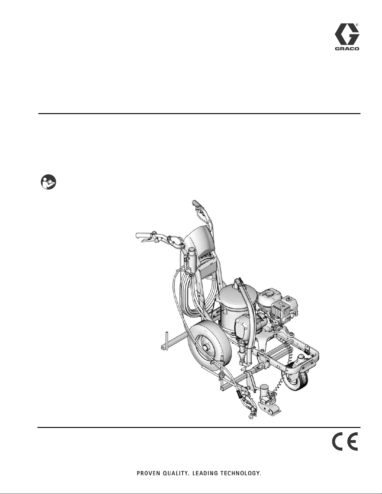
Application Methods
LineLazer™ IV 3900, 5900, 200HS Auto-Layout™,
312307E
and 250SPS System Airless Line Stripers
- For the application of line striping materials. For professional use only. Not for use in
explosive atmospheres. -
3300 psi (22.8 MPa, 228 bar) Maximum Working Pressure.
Important Safety Instructions
Read all warnings and instructions in the
Operations Manual 312190. Save these
instructions.
EN
ti10233a
Page 2

Table of Contents
Quick Guide - LineLazer IV Auto Layout System . 3
Quick Guide - LLIV 250SPS . . . . . . . . . . . . . . . . . . 4
LineLazer IV Auto-Layout System . . . . . . . . . . . . . 5
LLIV 250SPS . . . . . . . . . . . . . . . . . . . . . . . . . . . . . . . 5
Calibration . . . . . . . . . . . . . . . . . . . . . . . . . . . . . . . . 6
Measure Mode . . . . . . . . . . . . . . . . . . . . . . . . . . . . . 7
Basic Stall Layout: Parking Mode . . . . . . . . . . . . . 8
Basic Stall Layout: Parking Calculation . . . . . . . . 9
Basic Stall Layout: Parking Mode . . . . . . . . . . . . 10
Basic Stall Layout: Parking Mode . . . . . . . . . . . . 11
Basic Stall Layout: Striping Mode . . . . . . . . . . . . 12
Island Stall Layout: Parking Mode . . . . . . . . . . . . 13
Island Stall Layout: Parking Mode . . . . . . . . . . . . 14
Island Stall Layout: Striping Mode . . . . . . . . . . . . 15
Radius Stall Layout: Parking Mode . . . . . . . . . . . 16
Radius Stall Layout: Parking Calculation . . . . . . 17
Radius Stall Layout: Parking Mode . . . . . . . . . . . 18
Radius Stall Layout: Parking Calculation . . . . . . 19
Radius Stall Layout: Parking Mode . . . . . . . . . . . 20
Radius Stalls Paint lines . . . . . . . . . . . . . . . . . . . . 21
Angle Stall Layout: Parking Mode . . . . . . . . . . . . 22
Angle Stall Layout: Angle Calculation . . . . . . . . . 23
Angle Stall Layout: Parking Mode . . . . . . . . . . . . 24
Angle Stall Layout: Striping Mode . . . . . . . . . . . . 25
Cross Hatch Layout: Parking Mode . . . . . . . . . . . 26
Cross Hatch Layout: Striping Mode . . . . . . . . . . . 27
Cross Hatch Layout: Striping Mode . . . . . . . . . . . 28
Marker Mode Layout: Center Lines and Lane Lines
Mode . . . . . . . . . . . . . . . . . . . . . . . . . . . . . . . . . 29
Line Layout: Road Mode . . . . . . . . . . . . . . . . . . . . 30
Notes . . . . . . . . . . . . . . . . . . . . . . . . . . . . . . . . . . . . 31
Graco Standard Warranty . . . . . . . . . . . . . . . . . . . 32
NOTE: For Best results, always dot in the same direction.
NOTE: Minimum RPM for placing dots is 2600.
NOTE: Minimum pressure on LLIV 250SPS is 1000 psi.
2 312307E
Page 3
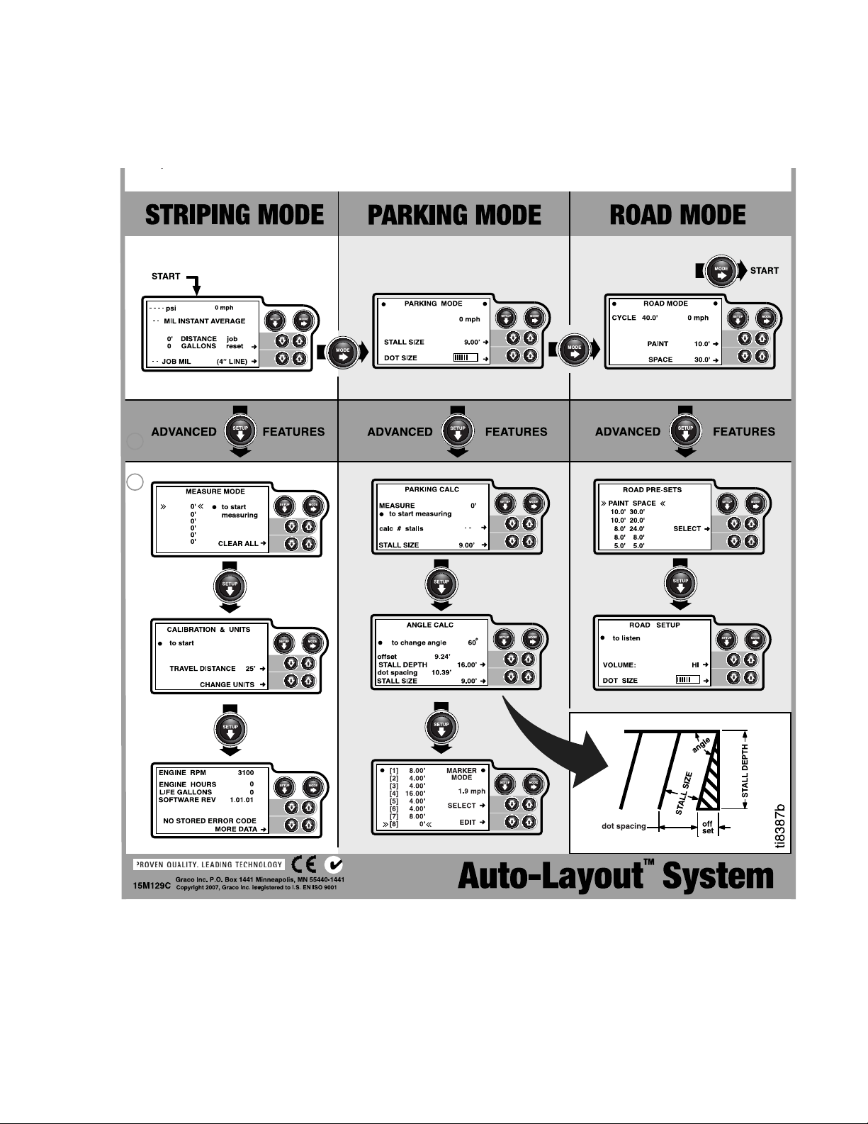
Quick Guide - LineLazer IV Auto Layout System
Quick Guide - LineLazer IV Auto Layout System
ti8387b_front
312307E 3
Page 4
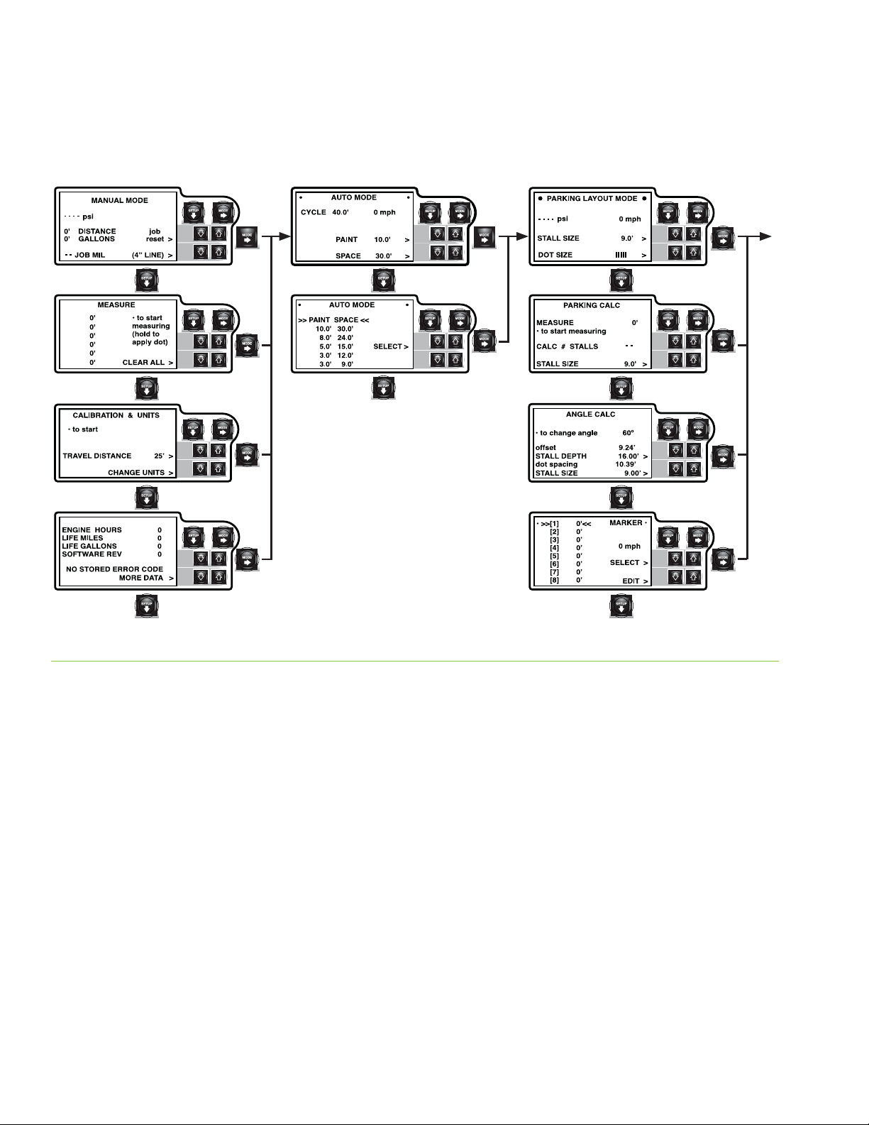
Quick Guide - LLIV 250SPS
Quick Guide - LLIV 250SPS
4 312307E
Page 5
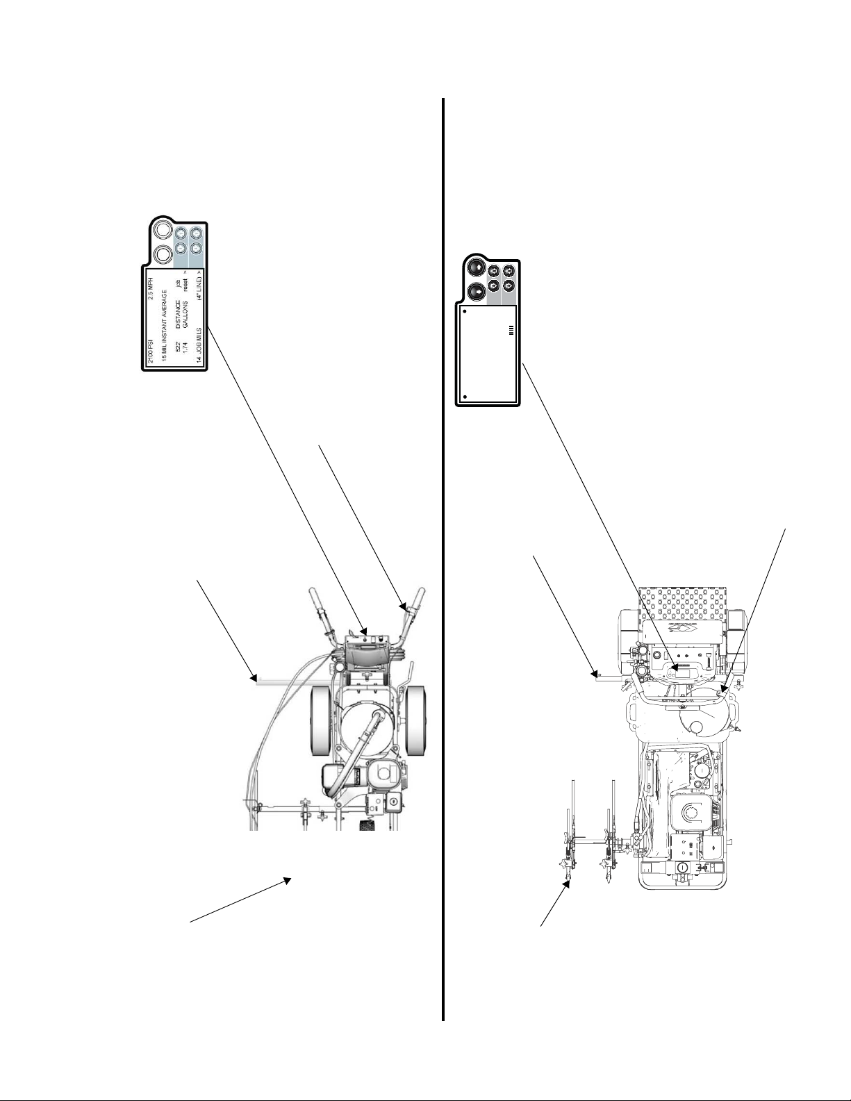
Display
Rear Gun Mount
Calibration Bar &
02'(
6(783
Display
PSK
SVL
3DUNLQJ/D\RXW0RGH
67$//6,=(ҋ!
'276,=( !
Remote Switch
Gun Trigger Control
Bar
Calibration
ti10100a
Spray Module with
Aerosol Chalk Can
Spray Tip
Gun and 286111
LineLazer IV Auto-Layout System
312307E 5
LLIV 250SPS
Page 6
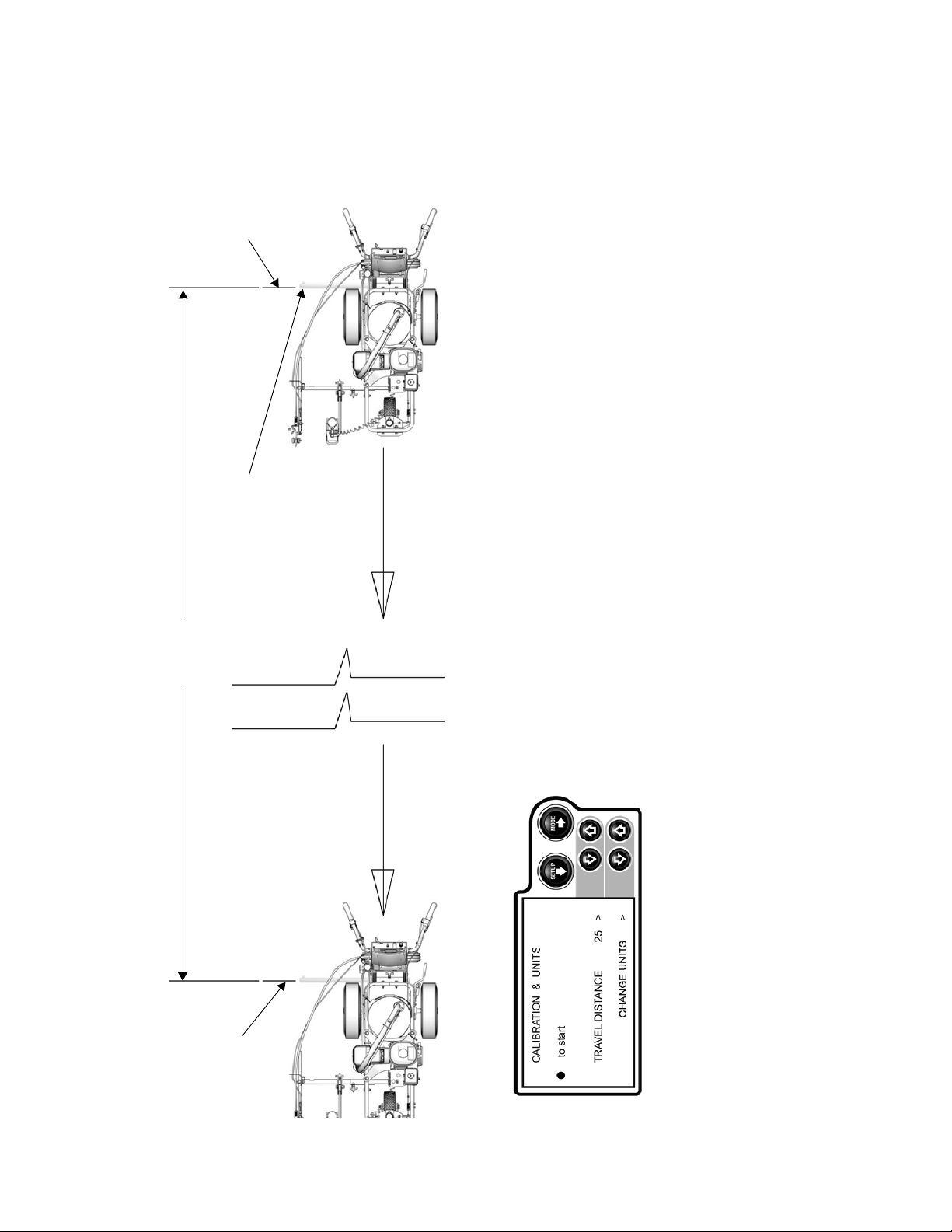
START
25 feet
Rotate calibration arm
FINISH
pointing down to ground
CALIBRATION AND UNITS
Press REMOTE SWITCH to START calibration. Press REMOTE SWITCH to FINISH
calibration.
IMPORTANT NOTE: For best results, calibrate to a minimum of 25 ft. Use only steel
measuring tape. Precise start and stop are necessary. Calibration distance above 100 ft is
not recommended due to inaccuracy with setting up the course. Tire air pressure
variations can negatively impact accuracy of unit.
CHANGE UNITS changes all displayed values to metric or standard units of measure.
ti10101a
Calibration
Minimum 25 ft precision course
6 312307E
Page 7
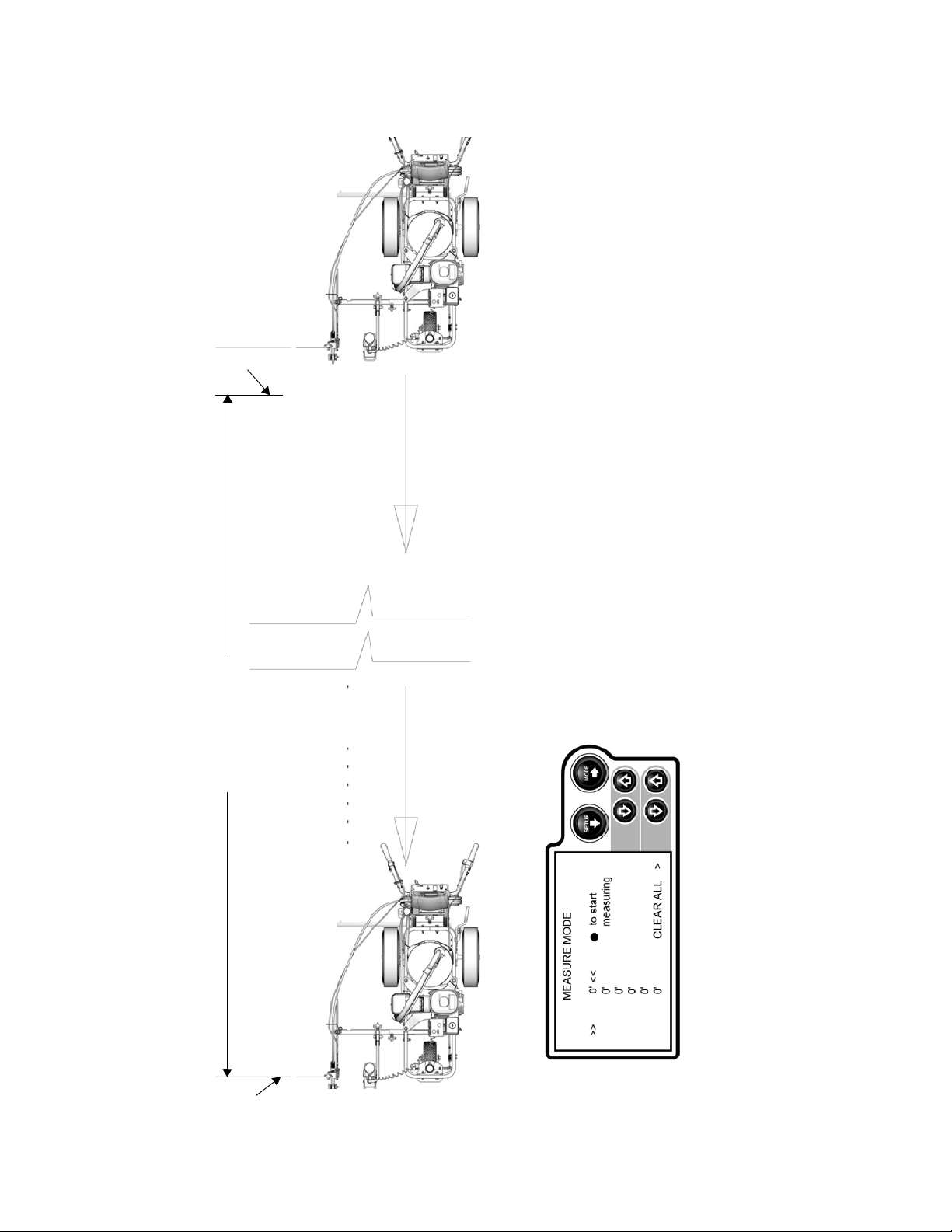
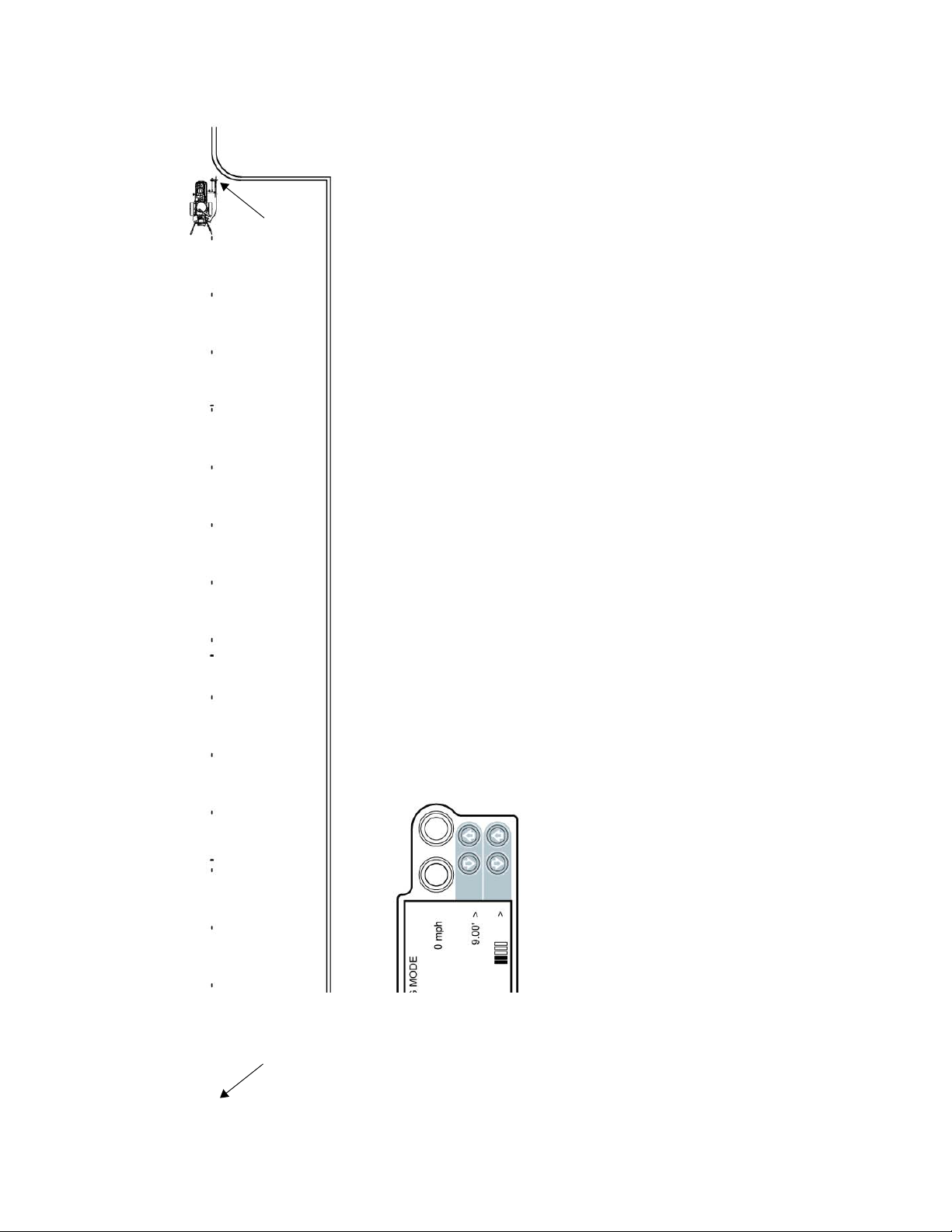
START
Measurements automatically increment down on screen, last measurements display
at all times.
MEASURE MODE
At any time while in MEASURE MODE, momentarily hold down REMOTE SWITCH
to apply dot. Holding down REMOTE SWITCH will produce continuous dotted line 1
foot dot spacing when moving, used for pre-marking.
Press REMOTE SWITCH to START. Press REMOTE SWITCH to FINISH.
Measured Distance
NOTE: The striper measures moving forward or reverse.
ti10102a
Measure Mode
Used for measuring and marking specific distances
312307E 7
FINISH
Page 8
NOTE: For Best results, always dot in the same direction.
NOTE: Minimum RPM for placing dots is 2600.
NOTE: Minimum pressure on LLIV 250SPS is 1000 psi.
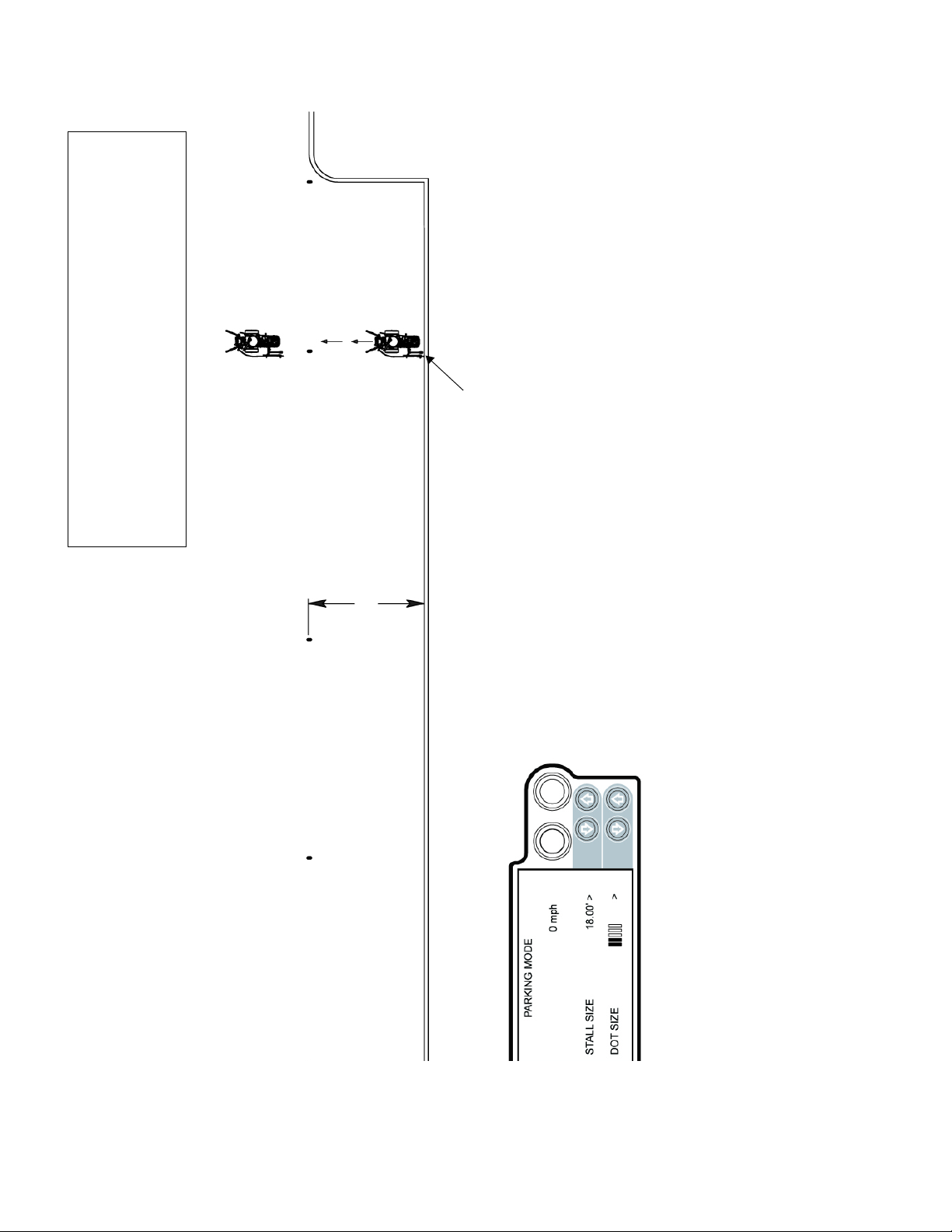
FINISH
START
PARKING MODE
Press REMOTE SWITCH to START and FINISH.
Establish enough reference dots to guide striper for applying stall lines.
In this case, 18 ft from inner curbing.
18 feet
15 stalls
ti10103a
Basic Stall Layout: Parking Mode
Establishing outer boundary with reference dots
8 312307E
Page 9
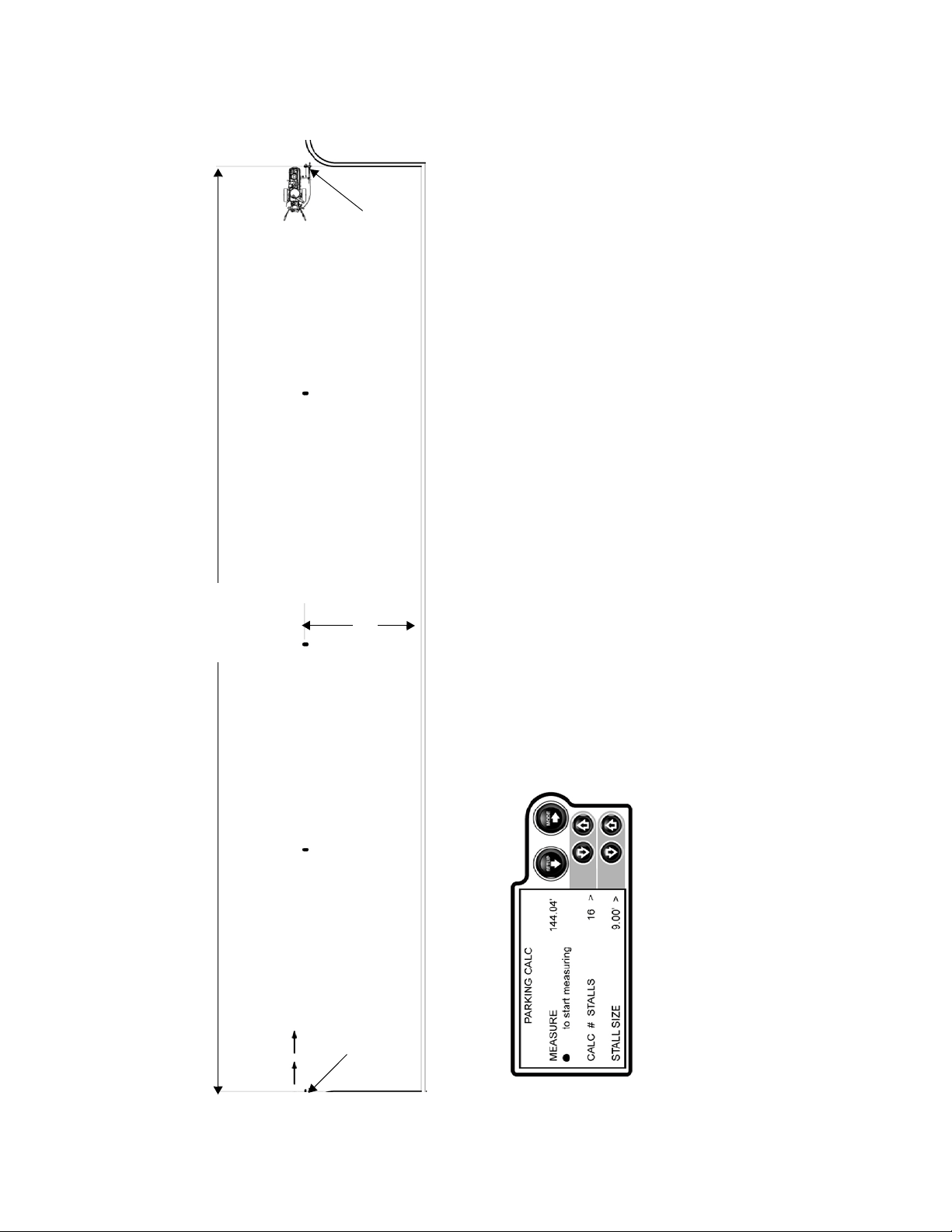
FINISH
144.04 feet
18 feet
START
16 Stalls
PARKING CALC
Press REMOTE SWITCH to START and FINISH calculation. IMPORTANT NOTE:
Start-point and finish-point accuracy is critical.
Press remote switch to start measuring. Follow the established 18 ft reference dots,
measure from start to finish. Press remote switch to stop measuring.
Use up/down arrows to adjust number of stalls as desired.
NOTE: System automatically transfers the calculated STALL SIZE from PARKIN G
CALC to PARKING MODE screen.
ti10104a
Basic Stall Layout: Parking Calculation
Measure for automatic calculation or select desired stall size
312307E 9
Page 10
FINISH
16 Stalls
Utilizing calculated stall size, apply dots, traveling from start to finish.
NOTE: System automatically transfers the calculated STALL SIZE from
PARKING MODE
Press REMOTE SWITCH to START and FINISH dots.
START
PARKING CALC screen if desired.
ti10105a
Basic Stall Layout: Parking Mode
Mark dots at beginning of each stall
10 312307E
Page 11

FINISH
PARKING MODE
Press remote switch at start while following curbing as a reference applying
evenly spaced dots. Press remote switch at finish to stop dots.
Establish first stall perpendicular to curb as shown (if curbing does not allow
Press REMOTE SWITCH to START and FINISH dots.
room for striper).
16 Stalls
9 ft
Basic Stall Layout: Parking Mode
Mark dots at end of each stall
312307E 11
START
ti10106a
Page 12

STRIPING MODE
Simply connect the dots with your sprayer.
ti10107a
Basic Stall Layout: Striping Mode
Paint lines (connect the dots)
12 312307E
Page 13

32 Stalls
START
Establish enough reference dots to guide striper for applying stall lines by
using PARKING M O DE measuring 18 ft out from centerline.
NOTE: The striper measures moving forward or reverse, as shown,
PARKING MODE
Press REMOTE SWITCH to start and stop dots.
placing evenly spaced dots at desired spacing.
START
Island Stall Layout: Parking Mode
Establish the center line and outer boundary first
312307E 13
ti10108a
Page 14

NOTE: For Best results, always dot in the same direction.
START
NOTE: Minimum RPM for placing dots is 2600.
NOTE: Minimum pressure on LLIV 250SPS is 1000 psi.
32 Stalls
START
PARKING M O DE
Press REMOTE SWITCH to start and stop dots.
NOTE: See Basic Stalls section (pages 4-8) to automatically measure
and calculate stall size.
ti10109a
Island Stall Layout: Parking Mode
Place dots at the beginning of each stall line
14 312307E
Page 15

STRIPING MODE
Simply connect the dots with the striper.
ti10110a
Island Stall Layout: Striping Mode
Paint lines (connect the dots)
312307E 15
Page 16

FINISH
START
15 Stalls
NOTE: For best results, always dot in the same direction.
NOTE: Minimum RPM for placing dots is 2600.
NOTE: Minimum pressure on LLIV 250SPS is 1000 psi.
Establish enough reference dots to guide striper for measuring and
PARKING MODE
18 ft
Press REMOTE SWITCH to START and FINISH.
applying stall lines. In this case, 18 feet from inner curbing.
ti10113b
Radius Stall Layout: Parking Mode
Place evenly spaced dots at beginning of each stall
16 312307E
Page 17

121.49
FINISH
18 feet
Radius Stall Layout: Parking Calculation
Measure inner perimeter distance
NOTE: Measure start-point and finish-point accuracy is critical.
Press remote switch at start, follow the curbing as a reference to guide striper along path
measuring from start to finish. Press remote switch at finish to stop measuring.
Use up/down arrows to adjust correct number of stalls. New parking stall size will display
under STALL SIZE. Establish first stall if curbing does not allow room for striper (in this
case 15 less 1 = 14 for the calculation).
NOTE: System automatically transfers the calculated STALL SIZE from PARKING CALC
PARKING MODE
Press REMOTE SWITCH to START and FINISH measuring.
START
ti10411a
to PARKING MODE screen.
312307E 17
Page 18

FINISH
15 Stalls
Press REMOTE SWITCH to START and FINISH dots.
ti10412a
Utilizing calculated stall size, apply dots, traveling from start to finish.
PARKING MODE
Establish first stall perpendicular to curb as shown (if curbing does not allow
room for striper).
NOTE: System automatically transfers the calculated STALL SIZE from
PARKING CALC to PARKING MODE screen.
Radius Stall Layout: Parking Mode
Mark dots at end of each stall
18 312307E
START
Page 19

141.79
FINISH
15 Stalls
NOTE: Start-point and finish-point accuracy is crucial.
Press remote switch at start to begin measuring. Follow the established 18 ft
reference dots measuring from start to finish. Press remote switch again to stop
measuring.
PARKING CALC
Press REMOTE SWITCH to START and FINISH measuring.
START
ti10413a
Use up/down arrows to adjust correct number of stalls.
CALC to PARKING MODE screen.
NOTE: System automatically transfers the calculated STALL SIZE from PARKI NG
Radius Stall Layout: Parking Calculation
Measure outer perimeter distance
312307E 19
Page 20

FINISH
15 Stalls
PARKING M O DE
Press REMOTE SWITCH to START and FINISH dots.
Utilizing calculated stall size, apply dots traveling from start to finish.
NOTE: System automatically transposes the calculated STALL SIZE
from PARKING CALC to PARKING MODE screen.
START
ti10414a
Radius Stall Layout: Parking Mode
Place evenly spaced dots at beginning of each stall
20 312307E
Page 21

STRIPING MODE
Simply connect the dots with the striper.
ti10116b
Radius Stalls
Paint lines
312307E 21
Page 22

START
NOTE: For best results, always dot in the same direction.
NOTE: Minimum RPM for placing dots is 2600.
NOTE: Minimum pressure on LLIV 250SPS is 1000 psi.
PARKING Mode
Press REMOTE SWITCH to START and FINISH dots.
Establish enough reference dots to guide striper for applying stall lines by
using PARKING MODE measuring 18 ft out from centerline.
NOTE: The striper measures moving forward or reverse, as shown, placing
32 Stalls
START
evenly-spaced dots at desired spacing.
ti10117b
Angle Stall Layout: Parking Mode
Establish the center line and outer boundary
22 312307E
Page 23

9.00
75°
14 Stalls
4.82
desired STALL DEPTH and STALL SIZE. System automatically calculates
ANGLE CALC
“offset” and “dot spacing”.
Press REMOTE SWITCH to adjust desired angle. Use up/down arrows to set
NOTE: System automatically transfers calculated “dot spacing” from ANGLE
CALC to PARKING MODE screen.
14 Stalls
Angle Stall Layout: Angle Calculation
Measure outer boundary
312307E 23
ti10118a
Page 24

START
14 Stalls
FINISH
14 Stalls
PARKING MODE
Press REMOTE SWITCH to START and FINISH dots.
If necessary, use PARKING CALC to determine how many 9.32 ft parking
stalls will fit.
ti10119a
Angle Stall Layout: Parking Mode
Mark dots at end of each stall
24 312307E
FINISH
Page 25

STRIPING MODE
Simply connect the dots with the striper.
ti10120a
Angle Stall Layout: Striping Mode
Paint lines (connect the dots)
312307E 25
Page 26

6 feet
FINISH
3 feet
NOTE: For Best results, always dot in the same direction.
NOTE: Minimum RPM for placing dots is 2600.
NOTE: Minimum pressure on LLIV 250SPS is 1000 psi.
Adjust STALL SIZE to achieve desired cross hatch spacing.
PARKING MODE
Press REMOTE SWITCH to START and FINISH dots.
Place dots around perimeter of area.
36 feet
START
Cross Hatch Layout: Parking Mode
Establish the boundary and apply dots at desired spacing
26 312307E
ti10121a
Page 27

STRIPING MODE
Simply connect the dots with the striper.
Paint interior by connecting the dots. If ends are rounded as shown,
make sure you establish this before painting.
Cross Hatch Layout: Striping Mode
Paint lines (connect the dots)
312307E 27
ti10122a
Page 28

Cross Hatch Layout: Striping Mode
Paint perimeter (connect the dots)
STRIPING MODE
Large or small, cross hatching jobs can be simplified by following
these simple steps, eliminating the inconsistencies found on many
job sites today.
ti10123a
28 312307E
Page 29

48.00’
8.00’ 8.00’
16.00’8.00’ 8.00’
4.00’ 4.00’
MARKER MODE
Automatic marker layout example shows typical lane line layout for reflective
markers. Set space sizes up to 8 consecutive measurements. By leaving
zeros in any space, AutoLayout will skip to the next measurement in a
continuous loop.
OTHER USES:
• Multiple spaced handicap stall layout
• Double line stalls
ti10126a
Marker Mode Layout: Center Lines and Lane Lines Mode
Paint lines (connect the dots)
312307E 29
Page 30

ROAD MODE
Automatic skipline layout for roads, bike trails, and airports.
ti10128a
Line Layout: Road Mode
Skip line
30 312307E
Page 31

Notes
Notes
312307E 31
Page 32

Graco Standard Warranty
Graco warrants all equipment referenced in this document which is manufactured by Graco and bearing its name to be free from defects in
material and workmanship on the date of sale to the original purchaser for use. With the exception of any special, extended, or limited warranty
published by Graco, Graco will, for a period of twelve months from the date of sale, repair or replace any part of the equipment determined by
Graco to be defective. This warranty applies only when the equipment is installed, operated and maintained in accordance with Graco’s written
recommendations.
This warranty does not cover, and Graco shall not be liable for general wear and tear, or any malfunction, damage or wear caused by faulty
installation, misapplication, abrasion, corrosion, inadequate or improper maintenance, negligence, accident, tampering, or substitution of
non-Graco component parts. Nor shall Graco be liable for malfunction, damage or wear caused by the incompatibility of Graco equipment with
structures, accessories, equipment or materials not supplied by Graco, or the improper design, manufacture, installation, operation or
maintenance of structures, accessories, equipment or materials not supplied by Graco.
This warranty is conditioned upon the prepaid return of the equipment claimed to be defective to an authorized Graco distributor for verification of
the claimed defect. If the claimed defect is verified, Graco will repair or replace free of charge any defective parts. The equipment will be returned
to the original purchaser transportation prepaid. If inspection of the equipment does not disclose any defect in material or workmanship, repairs will
be made at a reasonable charge, which charges may include the costs of parts, labor, and transportation.
THIS WARRANTY IS EXCLUSIVE, AND IS IN LIEU OF ANY OTHER WARRANTIES, EXPRESS OR IMPLIED, INCLUDING BUT NOT LIMITED
TO WARRANTY OF MERCHANTABILITY OR WARRANTY OF FITNESS FOR A PARTICULAR PURPOSE.
Graco’s sole obligation and buyer’s sole remedy for any breach of warranty shall be as set forth above. The buyer agrees that no other remedy
(including, but not limited to, incidental or consequential damages for lost profits, lost sales, injury to person or property, or any other incidental
or consequential loss) shall be available. Any action for breach of warranty must be brought within two (2) years of the date of sale.
GRACO MAKES NO WARRANTY, AND DISCLAIMS ALL IMPLIED WARRANTIES OF MERCHANTABILITY AND FITNESS FOR A
PARTICULAR PURPOSE, IN CONNECTION WITH ACCESSORIES, EQUIPMENT, MATERIALS OR COMPONENTS SOLD BUT NOT
MANUFACTURED BY GRACO. These items sold, but not manufactured by Graco (such as electric motors, switches, hose, etc.), are subject
to the warranty, if any, of their manufacturer. Graco will provide purchaser with reasonable assistance in making any claim for breach of these
warranties.
In no event will Graco be liable for indirect, incidental, special or consequential damages resulting from Graco supplying equipment hereunder,
or the furnishing, performance, or use of any products or other goods sold hereto, whether due to a breach of contract, breach of warranty, the
negligence of Graco, or otherwise.
FOR GRACO CANADA CUSTOMERS
The Parties acknowledge that they have required that the present document, as well as all documents, notices and legal proceedings entered into,
given or instituted pursuant hereto or relating directly or indirectly hereto, be drawn up in English. Les parties reconnaissent avoir convenu que la
rédaction du présent document ainsi que de tous les documents, avis et procédures judiciaires exécutés, donnés ou intentés à la suite de ou en
rapport, directement ou indirectement, avec les procédures concernées, sera en anglais.
ADDITIONAL WARRANTY COVERAGE
Graco does provide extended warranty and wear warranty for products described in the “Graco Contractor Equipment Warranty Program”.
Graco Information
For the latest information about Graco products, visit www.graco.com.
TO PLACE AN ORDER, contact your Graco distributor or call 1-800-690-2894 to identify the nearest distributor.
All written and visual data contained in this document reflects the latest product information available at the time of publication.
GRACO INC. AND SUBSIDIARIES • P.O. BOX 1441 • MINNEAPOLIS MN 55440-1441 • USA
Copyright 2007, Graco Inc. All Graco manufacturing locations are registered to ISO 9001.
Graco reserves the right to make changes at any time without notice.
For patent information, see www.graco.com/patents.
Original instructions. This manual contains English. MM 312307
Graco Headquarters: Minneapolis
International Offices: Belgium, China, Japan, Korea
www.graco.com
Revised March 2013
 Loading...