

Page 1
Instructions - Parts List
1590 Models
TI8926a
TI8924a
TI8928a
2150 Models
1040 Models
™
SaniForce
Diaphragm Pumps
1040, 1590, and 2150 Models
For use in sanitary applications. For professional use only.
Important Safety Instructions
Read all warnings and instructions in this
manual. Save these instructions.
120 psi (0.8 MPa, 8 bar) Maximum Fluid Working Pressure
120 psi (0.8 MPa, 8 bar) Maximum Air Input Pressure
Refer to the appropriate Pump Matrix on page 26, 34,
or 42 to determine the model number of your pump.
See page 3 for approval information.
311879Y
EN
Page 2

Contents
Models . . . . . . . . . . . . . . . . . . . . . . . . . . . . . . . . . . . 3
Warnings . . . . . . . . . . . . . . . . . . . . . . . . . . . . . . . . . 5
Installation . . . . . . . . . . . . . . . . . . . . . . . . . . . . . . . . 7
Operation . . . . . . . . . . . . . . . . . . . . . . . . . . . . . . . . 12
Maintenance . . . . . . . . . . . . . . . . . . . . . . . . . . . . . . 13
Troubleshooting . . . . . . . . . . . . . . . . . . . . . . . . . . . 14
Service . . . . . . . . . . . . . . . . . . . . . . . . . . . . . . . . . . 16
Pump and Repair Kit Matrix - 1040 Models . . . . . 26
Available 1040 Configurations . . . . . . . . . . . . . . 27
Parts - 1040 Models . . . . . . . . . . . . . . . . . . . . . . . . 28
Dimensional Drawing - 1040 Models . . . . . . . . . . 31
Technical Data - 1040 Models . . . . . . . . . . . . . . . . 32
Performance Chart - 1040 Models . . . . . . . . . . . . 33
Pump and Repair Kit Matrix - 1590 Models . . . . . 34
Available 1590 Configurations . . . . . . . . . . . . . . 35
Parts - 1590 Models . . . . . . . . . . . . . . . . . . . . . . . . 36
Dimensional Drawing - 1590 Models . . . . . . . . . . 39
Technical Data - 1590 Models . . . . . . . . . . . . . . . . 40
Performance Chart - 1590 Models . . . . . . . . . . . . 41
Pump and Repair Kit Matrix - 2150 Models . . . . . 42
Available 2150 Configurations . . . . . . . . . . . . . . 43
Options for Ram Mounting . . . . . . . . . . . . . . . . 43
Parts - 2150 Models . . . . . . . . . . . . . . . . . . . . . . . . 44
Parts - 2150 Models for Ram Mounting . . . . . . . . 48
Dimensional Drawing - 2150 Models . . . . . . . . . . 50
Technical Data - 2150 Models . . . . . . . . . . . . . . . . 51
Performance Chart - 2150 Models . . . . . . . . . . . . 52
Graco Warranties . . . . . . . . . . . . . . . . . . . . . . . . . . 54
Graco Information . . . . . . . . . . . . . . . . . . . . . . . . . 54
2 311879Y
Page 3
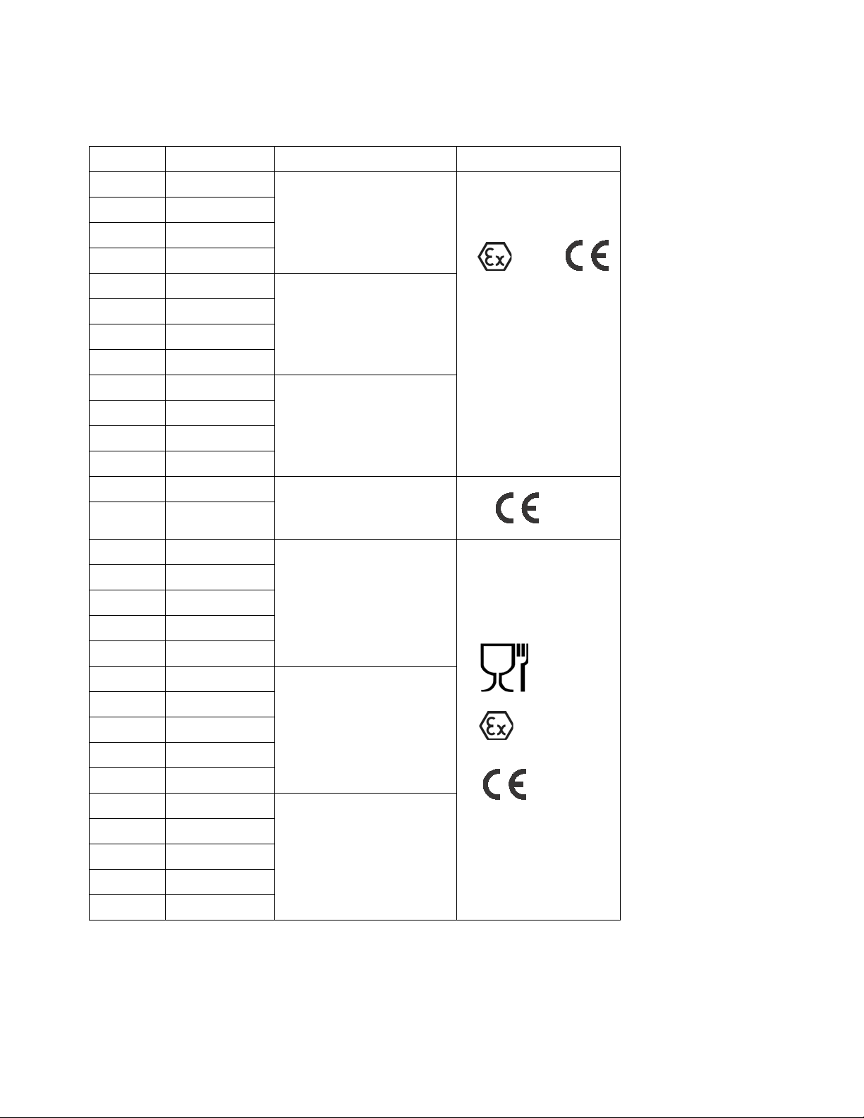
Models
II 2 G
II 2 G
Model Connections Description Approvals
FD1___ Flange
Models
FD7___ DIN
*FA1___ Flange
*FA7___ DIN
FD2___ Flange
FD8___ DIN
*FA2___ Flange
*FA8___ DIN
FD3___ Flange
FD9___ DIN
*FA3___ Flange
*FA9___ DIN
24G743 Flange
24G744 Flange
*FA1111 Flange
*FA7111 DIN
FD1111 Flange
1040 AODD Pump
1590 AODD Pump
2150 AODD Pump
2150 AODD Pump
for Ram Mounting
1040 AODD Pump
FD7111 DIN
FD1211 Flange
*FA2111 Flange
*FA8111 DIN
FD2111 Flange
FD8111 DIN
FD2211 Flange
*FA3111 Flange
*FA9111 DIN
FD3111 Flange
FD9111 DIN
FD3211 Flange
* FA pumps have painted aluminum center sections that may exhibit signs of corrosion depending on cleaning solu-
tions used.
1590 AODD Pump
2150 AODD Pump
311879Y 3
Page 4
Models
Material Certification
Reference: SaniForce Product Family
Issue Date: November 1, 2011
All fluid contact materials in the SaniForce product family are FDA-Compliant and meet the United States
Code of Federal Regulations (CFR) Title 21, Section 177 or are of a corrosion resistant grade Stainless
Steel. This includes the below product groups:
1. SaniForce 515, 1040, 1590, 2150 Air-Operated Double Diaphragm Pumps
2. SaniForce 1590, 3150 HS Air-0perated Double Diaphragm Pumps
3. SaniForce 1590, 3150 HS 3-A Certified Air-Operated Double Diaphragm Pumps
4. SaniForce 5:1, 6:1 and 12:1 Air-Operated Piston Pumps
5. SaniForce Diaphragm Pump and Piston Pump Drum Unloaders
6. SaniForce Diaphragm Pump and Piston Pump Bin Evacuation Systems
Bradley A. Byron
Quality Manager
Graco Inc.
4 311879Y
Page 5
Warnings
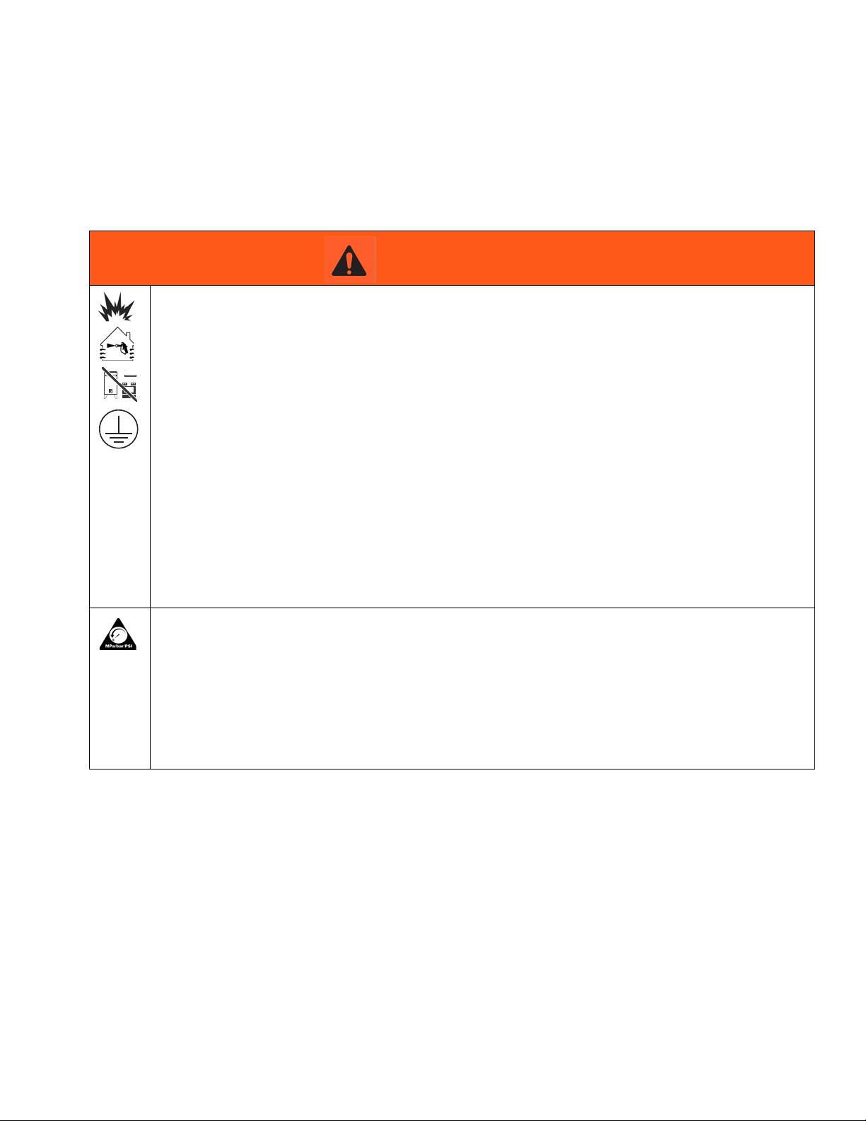
Warnings
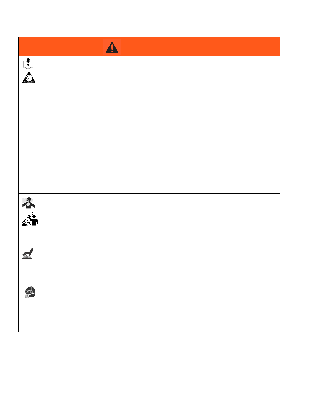
The following warnings are for the setup, use, grounding, maintenance, and repair of this equipment. The exclamation point symbol alerts you to a general warning and the hazard symbol refers to procedure-specific risk. When
these symbols appear in the body of this manual, refer back to these Warnings. Additional, product-specific warnings
may be found throughout the body of this manual where applicable.
WARNING
FIRE AND EXPLOSION HAZARD
Flammable fumes, such as solvent and paint fumes, in work area can ignite or explode. To help prevent
fire and explosion:
• Use equipment only in well ventilated area.
• Eliminate all ignition sources; such as pilot lights, cigarettes, portable electric lamps, and plastic
drop cloths (potential static arc).
• Keep work area free of debris, including solvent, rags and gasoline.
• Do not plug or unplug power cords, or turn power or light switches on or off when flammable fumes
are present.
• Ground all equipment in the work area. See Grounding instructions.
• Use only grounded hoses.
• Hold gun firmly to side of grounded pail when triggering into pail.
• If there is static sparking or you feel a shock, stop operation immediately. Do not use equipment
until you identify and correct the problem.
• Keep a working fire extinguisher in the work area.
PRESSURIZED EQUIPMENT HAZARD
Fluid from the gun/dispense valve, leaks, or ruptured components can splash in the eyes or on skin and
cause serious injury.
• Follow the Pressure Relief Procedure when you stop spraying and before cleaning, checking, or
servicing equipment.
• Tighten all fluid connections before operating the equipment.
• Check hoses, tubes, and couplings daily. Replace worn or damaged parts immediately.
311879Y 5
Page 6
Warnings
WARNING
EQUIPMENT MISUSE HAZARD
Misuse can cause death or serious injury.
• Do not operate the unit when fatigued or under the influence of drugs or alcohol.
• Do not exceed the maximum working pressure or temperature rating of the lowest rated system
component. See Technical Data in all equipment manuals.
• Use fluids and solvents that are compatible with equipment wetted parts. See Technical Data in all
equipment manuals. Read fluid and solvent manufacturer’s warnings. For complete information
about your material, request MSDS from distributor or retailer.
• Do not leave the work area while equipment is energized or under pressure. Turn off all equipment
and follow the Pressure Relief Procedure when equipment is not in use.
• Check equipment daily. Repair or replace worn or damaged parts immediately with genuine
manufacturer’s replacement parts only.
• Do not alter or modify equipment.
• Use equipment only for its intended purpose. Call your distributor for information.
• Route hoses and cables away from traffic areas, sharp edges, moving parts, and hot surfaces.
• Do not kink or over bend hoses or use hoses to pull equipment.
• Keep children and animals away from work area.
• Comply with all applicable safety regulations.
TOXIC FLUID OR FUMES HAZARD
Toxic fluids or fumes can cause serious injury or death if splashed in the eyes or on skin, inhaled, or
swallowed.
• Read MSDSs to know the specific hazards of the fluids you are using.
• Route exhaust away from work area. If diaphragm ruptures, fluid may be exhausted into the air.
• Store hazardous fluid in approved containers, and dispose of it according to applicable guidelines.
BURN HAZARD
Equipment surfaces and fluid that’s heated can become very hot during operation. To avoid severe
burns:
• Do not touch hot fluid or equipment.
PERSONAL PROTECTIVE EQUIPMENT
You must wear appropriate protective equipment when operating, servicing, or when in the operating
area of the equipment to help protect you from serious injury, including eye injury, hearing loss,
inhalation of toxic fumes, and burns. This equipment includes but is not limited to:
• Protective eyewear, and hearing protection.
• Respirators, protective clothing, and gloves as recommended by the fluid and solvent manufacturer.
6 311879Y
Page 7
Installation
"
Y
W
Installation
General Information
• FA pumps have painted aluminum center sections
that may exhibit signs of corrosion depending on
cleaning solutions used.
• The typical installations shown in Figs. 2-4 are only
guides for selecting and installing system components. Contact your Graco distributor for assistance
in planning a system to suit your needs.
• Always use genuine Graco parts and accessories.
• Reference numbers and letters in parentheses refer
to the callouts in the figures and the parts lists on
pages 28-30, 36-38, and 44-46.
The pump is very heavy (see Technical Data on pages
32, 40, and 51 for specific weights). If the pump must
be moved, follow the pressure relief procedure on
page 12 and have two people to lift the pump by grasping the outlet manifold securely or use appropriate lifting equipment.
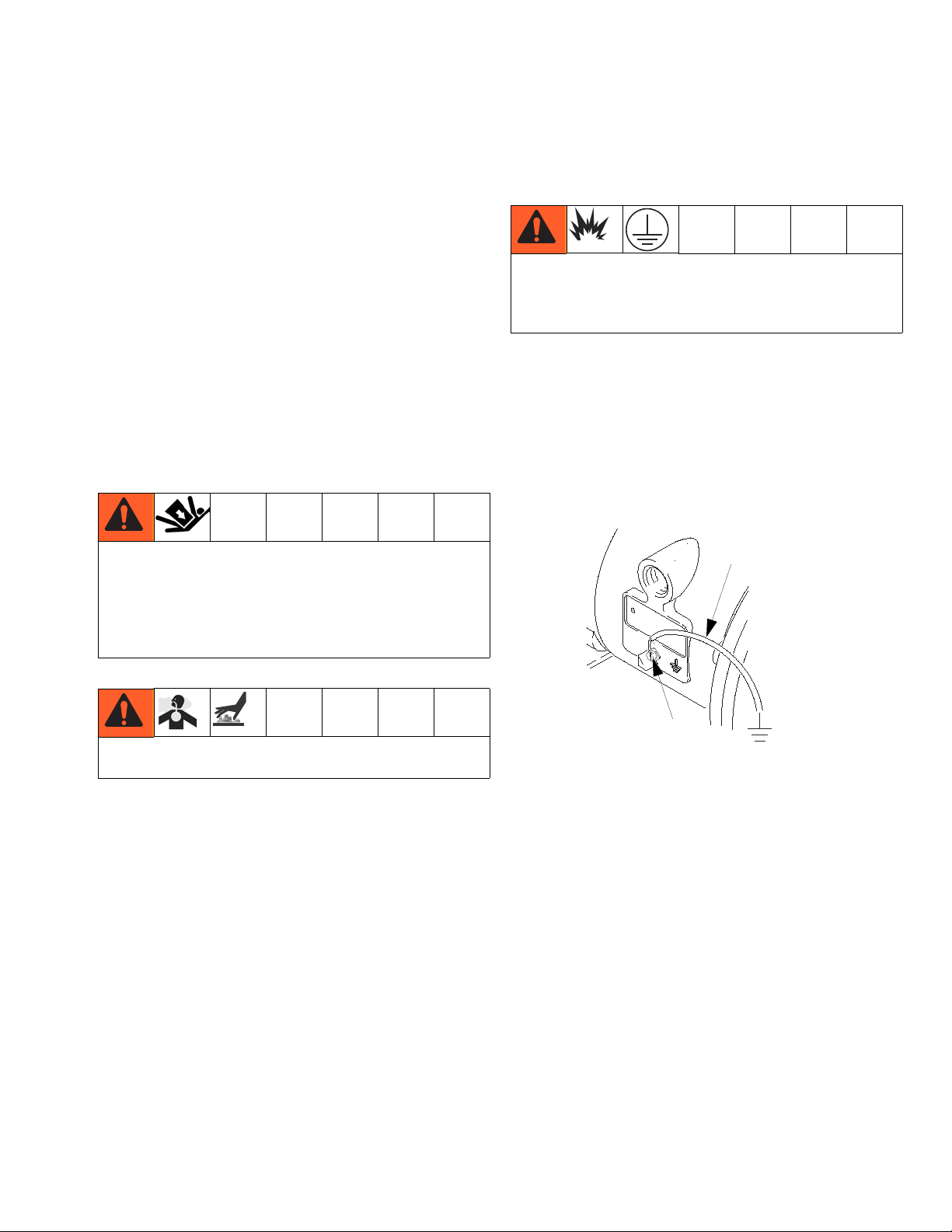
Grounding
The equipment must be grounded. Grounding reduces
the risk of static and electric shock by providing an
escape wire for the electrical current due to static build
up or in the event of a short circuit.
• Pump: Connect a ground wire and clamp as shown
in Fig. 1. Loosen the grounding screw (W). Insert
one end of a 12 ga (1.5 mm²) minimum ground wire
(Y) behind the grounding screw and tighten the
screw securely. Connect the clamp end of the
ground wire to a true earth ground. Order Part No.
238909 Ground Wire and Clamp.
F
To reduce the risk of serious injury due to burns, insulate and/or label the pump before pumping hot fluids.
IG. 1
• Fluid hoses: Use only grounded hoses with a maximum of 500 ft. (150 m) combined hose length to
ensure grounding continuity.
Tightening Clamps Before First Use
After you unpack the pump, and before you use it for the
• Air compressor: Follow the manufacturer’s recommendations.
first time, check all clamps and tighten as necessary.
• All solvent pails used when flushing: Follow the local
code. Use only metal pails, which are conductive.
Do not place the pail on a non-conductive surface,
such as paper or cardboard, which interrupts the
grounding continuity.
311879Y 7
• Fluid supply container: Follow the local code.
Page 8
Installation
Mountings
NOTICE
The pump exhaust air may contain contaminants. Ventilate to a remote area if the contaminants could affect
your fluid supply. See Air Exhaust Ventilation on page
11.
• Be sure the mounting surface can support the
weight of the pump, hoses, and accessories, as well
as the stress caused during operation.
• For all mountings, be sure the pump is bolted
directly to the mounting surface.
• For ease of operation and service, mount the pump
so the air valve cover (2), air inlet, and fluid inlet and
outlet ports are easily accessible.
In the step below, do not connect the quick-disconnect
coupler (D) on the air hose to the mating fitting on the
pump until you are ready to operate the pump. Connecting the coupler too early can result in unintentional
operation of the pump, leading to serious injury from
moving parts, splashing fluid in the eyes or on the skin,
and contact with hazardous fluids.
2. Install a grounded, flexible air hose (A) between the
accessories and the 1/2 npt(f) pump air inlet (N).
See Fig. 5. Use a minimum 3/8 in. (9.5 mm) ID air
hose. Screw an air line quick disconnect coupler (D)
onto the end of the air hose (A), and screw the mating fitting into the pump air inlet snugly.
Air Line
A bleed-type master air valve (B) is required in the system to relieve air trapped between this valve and the
pump. Trapped air can cause the pump to cycle unexpectedly, which could result in serious injury, including
splashing in the eyes or on the skin, injury from moving
parts, or contamination from hazardous fluids. See
F
IG. 2.
1. Install the air line accessories as shown in FIG. 2.
Mount these accessories on the wall or on a
bracket. Be sure the air line supplying the accessories is grounded.
a. Install an air regulator (C) and gauge to control
the fluid pressure. The fluid outlet pressure will
be the same as the setting of the air regulator.
b. Locate one bleed-type master air valve (B)
close to the pump and use it to relieve trapped
air. See the WARNING above. Locate the other
master air valve (E) upstream from all air line
accessories and use it to isolate them during
cleaning and repair.
Fluid Suction Line
1. Use flexible, grounded fluid hoses.
2. For best sealing results, use a standard tri-clamp or
DIN style sanitary gasket of a flexible material such
as EPDM, Buna-N, fluoroelastomer, or silicon.
3. If the fluid inlet pressure to the pump is more than
25% of the outlet working pressure, the ball check
valves will not close fast enough, resulting in inefficient pump operation.
4. At inlet fluid pressures greater than 15 psi (0.1 MPa,
1 bar), diaphragm life will be shortened.
5. See the Technical Data on pages 32, 40, and 51 for
maximum suction lift (wet and dry).
c. The air line filter (F) removes harmful dirt and
moisture from the compressed air supply.
8 311879Y
Page 9
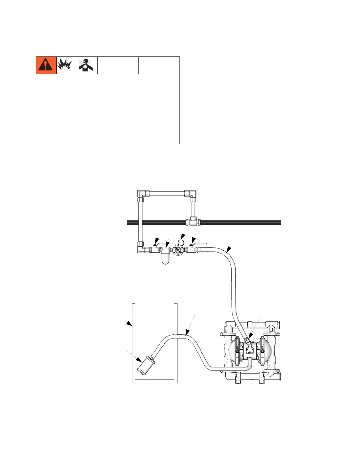
Fluid Outlet Line
TI8930a
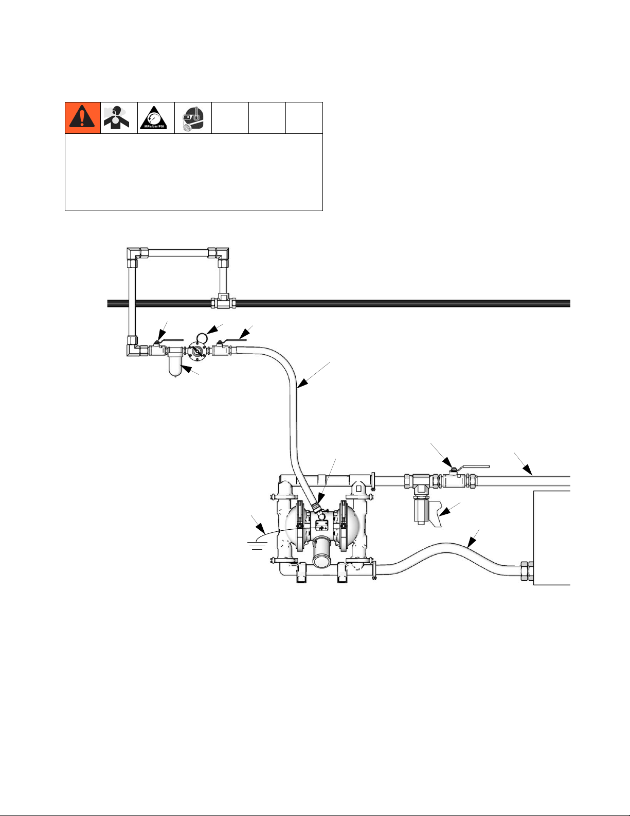
Key:
A Air supply line
B Bleed-type master air valve
(required for pump)
C Air regulator
D Air line quick disconnect
E Master air valve (for accessories)
F Air line filter
G Flexible fluid suction line
J Fluid drain valve (required)
K Fluid shutoff valve
L Flexible fluid line
Y Ground wire (required; see page
7 for installation instructions)
E
F
C
B
A
K
L
J
G
Y
D
A fluid drain valve (J) is required to relieve pressure in
the hose if it is plugged. The drain valve reduces the
risk of serious injury, including splashing in the eyes or
on the skin, or contamination from hazardous fluids
when relieving pressure. Install the valve close to the
pump fluid outlet. See F
IG. 2.
Installation
1. Use flexible grounded fluid hoses (L).
2. For best sealing results, use a standard tri-clamp or
DIN style sanitary gasket of a flexible material such
as EPDM, Buna-N, fluoroelastomer, or silicon
3. Install a fluid drain valve (J) near the fluid outlet. See
the WARNING above, and F
IG. 2.
4. Install a shutoff valve (K) in the fluid outlet line.
F
IG. 2 Typical Floor-Mount Installation
311879Y 9
Page 10
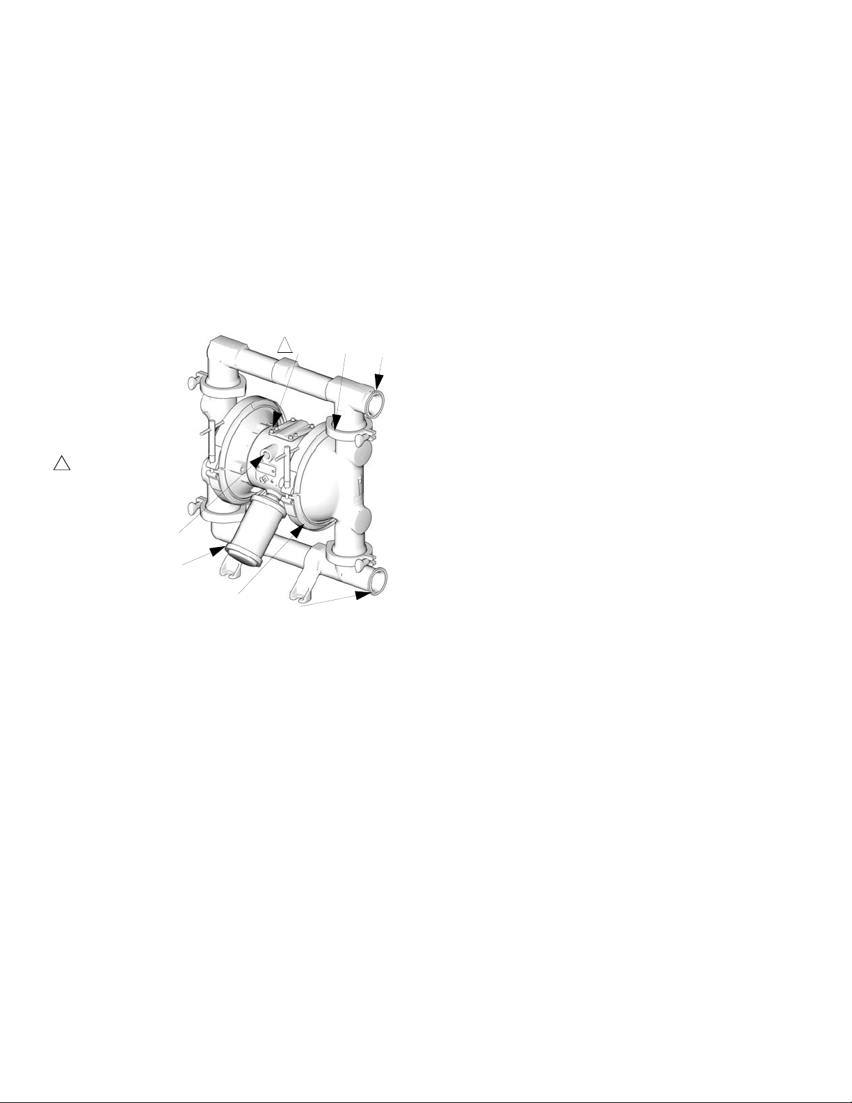
Installation
Key:
N 1/2 npt(f) air inlet port
P Muffler (air exhaust
port is 3/4 npt(f)
R Fluid inlet port
S Fluid outlet port
113 Manifold clamps
3 Air valve screws
Torque to
28-30 in-lb
(3.2-3.7 N•m)
1
1
N
3 113
S
R
P
106
TI8926a
Changing the Orientation of the Fluid Inlet
and Outlet Ports
The pump is shipped with the ports facing the same
direction. To reverse the orientation of the ports:
1. Remove the clamps holding the inlet and/or outlet
manifold to the covers.
2. Reverse the manifold and reattach. Install and
tighten clamps snugly.
F
IG. 3
10 311879Y
Page 11
Air Exhaust Ventilation
Key:
A Air supply line
B Bleed-type master air valve
(required for pump)
C Air regulator
D Air line quick disconnect
E Master air valve (for accessories)
F Air line filter
PMuffler
T Grounded air exhaust hose
U Container for remote air exhaust
P
U
T
D
A
B
C
F
E
TI8931a
Be sure the system is properly ventilated for your type
of installation. When pumping flammable or hazardous
fluids, you must vent the exhaust to a safe place, away
from people, animals, food handling areas, and all
sources of ignition.
Diaphragm failure will cause the fluid being pumped to
exhaust with the air. Place an appropriate container at
the end of the air exhaust line to catch the fluid. See
F
IG. 4.
The air exhaust port is 3/4 npt(f). Do not restrict the air
exhaust port. Excessive exhaust restriction can cause
erratic pump operation.
Installation
To provide a remote exhaust:
1. Remove the muffler (P) from the pump air exhaust
port.
2. Install a grounded air exhaust hose (T) and connect
the muffler (P) to the other end of the hose. The
minimum size for the air exhaust hose is 3/4 in. (19
mm) ID. If a hose longer than 15 ft (4.57 m) is
required, use a larger diameter hose. Avoid sharp
bends or kinks in the hose.
3. Place a container (U) at the end of the air exhaust
line to catch fluid in case a diaphragm ruptures. See
F
IG. 4.
IG. 4 Venting Exhaust Air
F
311879Y 11
Page 12
Operation
Operation
Pressure Relief Procedure
The equipment stays pressurized until pressure is
manually relieved. To reduce the risk of serious injury
from pressurized fluid or splashing fluid, follow this
procedure whenever you stop pumping and before
cleaning, checking, or servicing equipment.
1. Shut off the air to the pump.
2. Open the dispensing valve, if used.
3. Open the fluid drain valve to relieve fluid pressure,
having a container ready to catch the drainage.
Sanitize the Pump Before First Use
It is the user’s responsibility to properly sanitize the
pump before first use. It is up to the user whether this
will include disassembling and cleaning individual parts
or simply flushing pump with a sanitizing solution. As
necessary, follow the steps under Starting and Adjust-
ing the Pump below, under the Service section on
page 16, or under Flushing on page 13.
Starting and Adjusting the Pump
1. Be sure the pump is properly grounded. Refer to
Grounding on page 4.
2. Check connections to be sure they are tight. Tighten
fluid inlet and outlet connections securely.
3. Place the suction tube (if used) in fluid to be
pumped.
NOTE: If fluid inlet pressure to the pump is more than
25% of outlet working pressure, the ball check valves
will not close fast enough, resulting in inefficient pump
operation.
4. Place the end of fluid hose (L) into an appropriate
container.
5. Close the fluid drain valve (J).
6. Back out the air regulator (C) knob, and open all
bleed-type master air valves (B, E).
7. If the fluid hose has a dispensing device, hold it
open while continuing with the following step.
8. Slowly increase air pressure with the air regulator
(C) until the pump starts to cycle. Allow the pump to
cycle slowly until all air is pushed out of the lines
and the pump is primed.
Never move or lift a pump under pressure. If dropped,
Pump Shutdown
the fluid section may rupture. Always follow the Pressure Relief Procedure before lifting the pump.
At the end of the work shift, relieve pressure.
12 311879Y
Page 13
Maintenance
Maintenance
Lubrication
The air valve is designed to operate unlubricated, however if lubrication is desired, every 500 hours of operation (or monthly) remove the hose from the pump air
inlet and add two drops of machine oil to the air inlet.
NOTICE
Do not over-lubricate the pump. Oil is exhausted
through the muffler and could contaminate your fluid
supply or other equipment. Excessive lubrication can
also cause the pump to malfunction.
Flushing
Insert suction tube into cleaning solution. Open air regulator to supply low pressure air to the pump. Run the
pump long enough to thoroughly clean the pump and
hoses. Close the air regulator. Remove the suction tube
from the cleaning solution and drain pump. Place suction tube in the fluid to be pumped.
Tightening Connections
Before each use, check all hoses for wear or damage,
and replace as necessary. Check to be sure all connections are tight and leak-free.
Preventive Maintenance Schedule
Establish a preventive maintenance schedule, based on
the pump’s service history. This is especially important
for prevention of spills or leakage due to diaphragm failure.
Flush the pump often enough to prevent the fluid you
are pumping from drying or freezing in the pump and
damaging it. Flushing schedule will be based on what
the pump is being used for. Use a compatible cleaning
solution and always cycle the pump during the entire
flushing process.
Always flush the pump and relieve the pressure before
storing it for any length of time.
311879Y 13
Page 14
Troubleshooting
Troubleshooting
• Relieve the pressure before checking or servicing
the equipment.
To reduce the risk of serious injury, whenever you are
instructed to relieve pressure, always follow the Pres-
sure Relief Procedure on page 12.
PROBLEM CAUSE SOLUTION
Pump cycles at stall or fails to hold
pressure at stall.
Pump will not cycle, or cycles once
and stops.
Pump operates erratically. Clogged suction line. Inspect; clear.
Worn check valve balls (301), seats
(201) or o-rings (202).
Air valve is stuck or dirty. Disassemble and clean air valve. See
Check valve ball (301) severely
worn and wedged in seat (201) or
manifold (102 or 103).
Check valve ball (301) is wedged
into seat (201), due to overpressurization.
Dispensing valve clogged. Relieve pressure and clear valve.
• Check all possible problems and causes before disassembling the pump.
Replace. See 18.
page 16. Use filtered air.
Replace ball and seat. See page 18.
Install Pressure Relief Valve
(see page 10).
Sticky or leaking balls (301). Clean or replace. See page 18.
Diaphragm ruptured. Replace. See pages 19-21.
Restricted exhaust. Remove restriction.
Air bubbles in fluid. Suction line is loose. Tighten.
Diaphragm ruptured. Replace. See pages 19-21.
Loose inlet manifold (102), damaged seal between manifold and
seat (201), damaged o-rings (202).
Loose diaphragm shaft bolt (107). Tighten or replace (pages 19-21).
Damaged o-ring (108). Replace. See pages 19-21.
Chattering - noisy operation. Check valve balls do not seat prop-
erly/cleanly due to imbalance
between fluid inlet and outlet line
sizing. Noise is accentuated with
light viscosity fluids.
Tighten manifold clamps (113), or
replace seats (201) or o-rings (202).
See page 18.
Reduce size/diameter of inlet line relative to outline line. Outlet line size
should not exceed pump size.
14 311879Y
Page 15

PROBLEM CAUSE SOLUTION
Troubleshooting
Leak in inlet or outlet sanitary fit-
Loose sanitary clamp. Tighten clamp.
ting.
Damaged or worn gasket. Replace gasket.
Misalignment of inlet/outlet hose or
pipe.
Use flexible hoses at pump inlet and
outlet.
Gasket does not seal. Use a standard sanitary gasket of flexi-
ble material such as EPDM, Buna-N,
fluoroelastomer, or silicon.
Fluid in exhaust air. Diaphragm ruptured. Replace. See pages 19-21.
Loose diaphragm shaft bolt (107). Tighten or replace. See pages 19-21.
Damaged o-ring (108). Replace. See pages 19-21.
Pump exhausts excessive air at
stall.
Worn air valve block (7), o-ring (6),
plate (8), pilot block (18), u-cups
Repair or replace. See page 16.
(10), or pilot pin o-rings (17).
Worn shaft seals (402). Replace. See pages 19-21.
Pump leaks air externally. Air valve cover (2) or air valve cover
Tighten screws. See page 16.
screws (3) are loose.
Pump leaks fluid externally from
ball check valves.
Air valve gasket (4) or air cover
Inspect; replace. See pages 16, 22-23.
gasket (22) is damaged.
Air cover screws (25) are loose. Tighten screws. See pages 22-23.
Loose manifolds (102, 103), damaged seal between manifold and
seat (201), damaged o-rings (202).
Tighten manifold clamps (113), or
replace seats (201) or o-rings (202).
See page 18.
311879Y 15
Page 16

Service
Service
Repairing the Air Valve
Tool Required
• Torque wrench
• Torx (T20) screwdriver or 7 mm (9/32 in.) socket
wrench
• Needle-nose pliers
• O-ring pick
• Lithium base grease
NOTE: Air Valve Repair Kits are available. Order Kit
255061 for models with stainless steel center housing.
Order Kit 236273 for models with aluminum center
housing. Parts included in Kit 255061 are marked with †,
and parts included in Kit 236273 are marked with ◆.
Use all the parts in the kit for the best results.
Disassembly
1. Relieve the pressure.
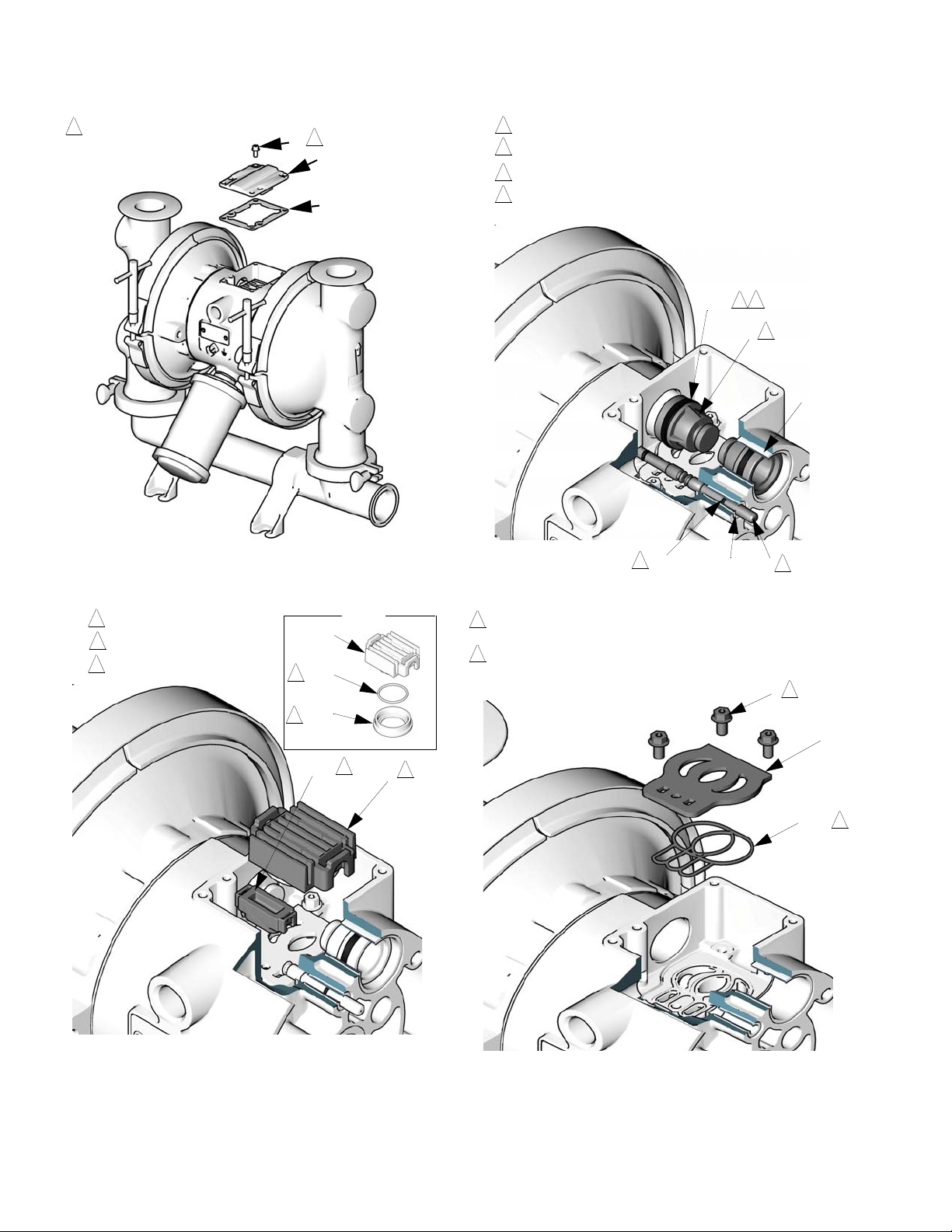
2. With a Torx (T20) screwdriver or 7 mm (9/32 in.)
socket wrench, remove the six screws (3), air valve
cover (2), and gasket (4). See F
3. Move the valve carriage (5) to the center position
and pull it out of the cavity. Remove the valve block
(7) and o-ring (6) from the carriage. Using a needle-nose pliers, pull the pilot block (18) straight up
and out of the cavity. See F
4. Pull the two actuator pistons (11) out of the bearings
(12). Remove the u-cup packings (10) from the pistons. Pull the pilot pins (16) out of the bearings (15).
Remove the o-rings (17) from the pilot pins. See
F
IG. 7.
5. Inspect the valve plate (8) in place. If damaged, use
a Torx (T20) screwdriver or 7 mm (9/32 in.) socket
wrench to remove the three screws (3). Remove the
valve plate (8). See F
IG. 8.
IG. 5.
IG. 6.
Reassembly
1. If you replaced the bearings (12, 15), reinstall as
explained on page 24. Reassemble the fluid section.
2. On models with aluminum center housing, install the
valve plate seal (55◆) into the groove at the bottom
of the valve cavity. The rounded side of the seal
must face down into the groove. See F
IG. 8.
3. Install the valve plate (8†) in the cavity, seal down.
Install the three screws (3), using a Torx (T20)
screwdriver or 7 mm (9/32 in.) socket wrench.
Tighten until the screws bottom out on the housing.
See F
IG. 8.
4. Install an o-ring (17†◆) on each pilot pin (16).
Grease the pins and o-rings. Insert the pins into the
bearings (15), narrow end first. See F
IG. 7.
5. Install a u-cup packing (10†◆) on each actuator piston (11), so the lips of the packings face the narrow
end of the pistons. See F
IG. 7.
6. Lubricate the u-cup packings (10†◆) and actuator
pistons (11). Insert the actuator pistons in the bearings (12), wide end first. Leave the narrow end of
the pistons exposed. See F
IG. 7.
7. Grease the lower face of the pilot block (18†◆) and
install so its tabs snap into the grooves on the ends
of the pilot pins (16). See F
IG. 6.
8. Grease the o-ring (6†◆) and install it in the valve
block (7†◆). Push the block onto the valve carriage
(5). Grease the lower face of the valve block. See
F
IG. 6.
9. Install the valve carriage (5) so its tabs slip into the
grooves on the narrow end of the actuator pistons
(11). See F
IG. 6.
10. Align the valve gasket (4†◆) and cover (2) with the
six holes in the center housing (1). Secure with six
screws (3), using a Torx (T20) screwdriver or 7 mm
(9/32 in.) socket wrench. Torque to 52-60 in-lb
(5.6-6.8 N•m). See F
IG. 5.
6. Inspect the bearings (12, 15) in place. See F
IG. 7.
The bearings are tapered and, if damaged, must be
removed from the outside. This requires disassembly of the fluid section. See page 24.
7. Clean all parts and inspect for wear or damage.
Replace as needed. Reassemble.
16 311879Y
Page 17
Service
TI9086A
2
2
2
4†
◆
3
Torque to 52-60 in-lb
(5.6-6.8 N•m)
TI9087A
Detail
5
◆
†6
◆
†7
2
1
3
2
3
See detail at right.
Grease.
Grease lower face.
18†
◆
5
3
1
TI9088A
TI9089A
2
1
3
4
11
12
17†
◆
15
16
4
1
2
Insert narrow end first
Grease
Install with lips facing narrow end of piston (11)
Insert wide end first
10†
◆
2
3
TI9090A
1
Tighten screws until they bottom out on the housing.
3
8
†
1
2
Rounded side of seal must face down. (Seal is used
only on models with aluminum center housing).
55
◆
2
FIG. 5
IG. 7
F
F
F
IG. 6
311879Y 17
IG. 8
Page 18

Service
TI8932a
2
1
Arrow (A) must point toward outlet manifold (103)
Radiused seating surface must face the ball (301).
Large chamfer on O.D. must face o-ring.
103
301*
201
202*
101
A
301*
201
202*
102
1
2
2
113
113
Ball Check Valve Repair
Tools Required
• O-ring pick
Disassembly
NOTE:
• A Fluid Section Repair Kit is available. Refer to the
Repair Kit Matrix parts section for the appropriate
pump size so that the correct kit for your pump is
ordered. Parts included in the kit are marked with an
asterisk, for example (202*). Use all the parts in the
kit for the best results.
• To ensure proper seating of the balls (301), always
inspect the seats (201) when replacing the balls.
Replace seats as necessary if seating surface
shows evidence of wear. Also, replace the o-rings
(202) as necessary. PTFE o-rings should be
replaced every time manifolds are removed.
1. Relieve the pressure. Disconnect all hoses.
2. Remove the pump from its mounting.
3. Remove the clamps (106) holding the outlet manifold (103) to the fluid covers (101). See F
IG. 9.
4. Remove the o-rings (202), seats (201), and balls
(301) from the manifold (103).
5. Turn the pump over and remove the inlet manifold
(102). Remove the o-rings (202), seats (201), and
balls (301) from the fluid covers (101).
Reassembly
1. Clean all parts and inspect for wear or damage.
Replace parts as needed.
2. Reassemble in the reverse order, following all notes
in F
IG. 9. Be sure the ball checks and manifolds are
assembled exactly as shown. The arrows (A) on the
fluid covers (101) must point toward the outlet manifold (103).
18 311879Y
F
IG. 9
Page 19

Standard Diaphragm Repair
TI9091A
1
Arrow (A) must point toward air valve.
B
23
101
A
1
1
106
106
NOTE: If your pump uses overmolded diaphragms, see
page 22.
Tools Required
• Torque wrench
• 15 mm socket wrench
• 19 mm open end wrench
• O-ring pick
• Lithium-base grease
Disassembly
NOTE: A Fluid Section Repair Kit is available. Refer to
page 27, 35, or 43 to order the correct kit for your pump.
Parts included in the kit are marked with an asterisk, for
example (401*). Use all the parts in the kit for the best
results.
Service
1. Relieve the pressure.
2. Remove the manifolds and disassemble the ball
check valves as explained on page 18.
3. Remove the clamps (106) holding the fluid covers
(101) to the air covers (23). Pull the fluid covers
(101) off the pump. See F
IG. 10.
F
IG. 10
311879Y 19
Page 20

Service
4. Loosen but do not remove the diaphragm shaft bolts
(107), using a 15 mm socket wrench on both bolts.
See F
IG. 11.
5. Unscrew one bolt from the diaphragm shaft (24) and
remove the o-ring (108), fluid side diaphragm plate
(105), diaphragm (403), backer (401) used only on
PTFE models, and air side diaphragm plate (104).
See F
IG. 11.
6. Pull the other diaphragm assembly and the diaphragm shaft (24) out of the center housing (1).
Hold the shaft flats with a 19 mm open end wrench,
and remove the bolt (107) from the shaft. Disassemble the remaining diaphragm assembly.
7. Inspect the diaphragm shaft (24) for wear or
scratches. If it is damaged, inspect the bearings (19)
in place. If the bearings are damaged, refer to page
24.
8. Reach into the center housing (1) with an o-ring pick
and hook the u-cup packings (402), then pull them
out of the housing. This can be done with the bearings (19) in place.
9. Clean all parts and inspect for wear or damage.
Replace parts as needed.
d. On PTFE models only, install the backer (401*)
on the bolt. Make certain the side marked AIR
SIDE faces the center housing (1).
e. Install the air side diaphragm plate (104) so the
rounded side faces the diaphragm (401). This
plate is stamped with its part number.
f. Apply medium-strength (blue) Loctite
® or equiv-
alent to the bolt (107) threads. Screw the bolt
into the shaft (24) hand tight.
3. Grease the length and ends of the diaphragm shaft
(24), and slide it through the housing (1).
4. Assemble the other diaphragm assembly to the
shaft as explained in step 2.
5. Hold one shaft bolt (107) with a wrench and torque
the other bolt to 60-70 ft-lb (81-95 N
•m) at 100 rpm
maximum.
6. Align the fluid covers (101) and the center housing
(1) so the arrows (A) on the covers face the same
direction as the air valve (B). Secure covers with the
clamps. See F
IG. 10.
Reassembly
1. Install the shaft u-cup packings (402*) so the lips
face out of the housing (1). Lubricate the packings.
See F
IG. 11.
2. Install the diaphragm assembly on one end of the
shaft (24) as follows:
a. Install the o-ring (108*) on the shaft bolt (107).
b. Install the fluid side diaphragm plate (105) on
the bolt so the rounded side faces the diaphragm (401).
NOTE: The fluid side diaphragm plate (105) is stainless
steel. This plate is not stamped with its part number. Be
sure to install this plate on the fluid side of the diaphragm.
c. Install the diaphragm (403*). Make certain the
side marked AIR SIDE faces the center
housing (1).
7. Reassemble the ball check valves and manifolds as
explained on page 18.
20 311879Y
Page 21

Service
TI8935a
TI8933a
TI8934a
Cutaway view, with
diaphragms in place
Lips face out of housing (1).
Rounded side faces diaphragm (401).
Air side must face center housing (1).
Grease.
Apply medium strength (blue) Loctite
® or
equivalent. Torque to 60-70 ft-lb (81-95 N•m)
at 100 rpm maximum.
Backer used on pumps with PTFE
diaphragms only.
1
2
345
6
105
107
403*
402*
19
24
24
1
104
105
401*
107
108*
403*
1
24 104
401*
4
2
3
3
6
2
5
4
4 2
3
2
63
1
5
FIG. 11
311879Y 21
Page 22

Service
ti10630a
106
24 104 403*
101
231
Overmolded Diaphragm Repair
NOTE: If your pump uses standard diaphragms, see
page 19.
Tools Required
• Torque wrench
• 19 mm open end wrench
• O-ring pick
• Lithium-base grease
Disassembly
NOTE: A Fluid Section Repair Kit is available. Refer to
page 27, 35, or 43 to order the correct kit for your pump.
Parts included in the kit are marked with an asterisk, for
example (401*). Use all the parts in the kit for the best
results.
1. Relieve the pressure.
2. Remove the manifolds and disassemble the ball
check valves as explained on page 18.
8. Reach into the center housing (1) with an o-ring pick
and hook the u-cup packings (402), then pull them
out of the housing. This can be done with the bearings (19) in place.
9. Clean all parts and inspect for wear or damage.
Replace parts as needed.
3. Remove the clamps (106) holding the fluid covers
(101) to the air covers (23). Pull the fluid covers
(101) off the pump. See F
IG. 12.
4. Once the fluid covers are removed, the diaphragm
on the side of the pump which was last pressurized
with air will be separated from the center section/air
cover. This allows you to grip the diaphragms.
5. Diaphragms are assembled handtight. To loosen,
grip both diaphragms securely around the outer
edge and rotate counterclockwise. One diaphragm
assembly will come free and the other will remain
attached to the shaft. Remove the freed diaphragm
(403) and air side plate (104).
6. Pull the opposite diaphragm assembly and shaft
(24) out of the center housing (1). Hold the shaft
flats with a 19 mm open end wrench and remove the
diaphragm and air side plate from the shaft.
7. Inspect the diaphragm shaft (24) for wear or
scratches. If it is damaged, inspect the bearings (19)
in place. If the bearings are damaged, refer to page
24.
FIG. 12
22 311879Y
Page 23

Reassembly
ti10631a
106
24 104 403*
101
231
Apply medium strength (blue) Loctite® or
equivalent to bolt (not shown).
5
5
B
A
To reduce the risk of serious injury, including
amputation, do not put your fingers or hand between
the air cover and the d4iaphragm.
1. Install the shaft u-cup packings (402*) so the lips
face out of the housing (1). Lubricate the packings.
IG. 13.
See F
2. Assemble the air side plate (104) onto the diaphragm (403). The wide, radiused side of the plate
must face the diaphragm. Apply medium-strength
(blue) Loctite
® or equivalent to the threads of the
diaphragm assembly. Screw the assembly into the
shaft (24) hand tight.
3. Grease the length and ends of the diaphragm shaft
(24). Insert the shaft/diaphragm assembly into one
side of the pump. Assemble the fluid cover (101)
and clamp (106) so the arrow (A) on the cover faces
the same direction as the air valve (B). Securely
tighten the clamp.
Service
FIG. 13
4. Assemble the other diaphragm assembly to the
shaft as explained in step 2. This diaphragm will be
lifted off the air cover at this point.
5. Supply the pump with low pressure air (less than 7
psi [.05 MPa, 0.5 bar]). The diaphragm will very
slowly pull onto the air cover (23). Find the pressure
that keeps the diaphragm close enough to clamp,
but does not let it contact the pilot pin.
NOTICE
Do not deform the diaphragm manually. The diaphragm
needs uniform pressure to deform properly for maximum life.
6. Assemble the fluid cover (101) and clamp (106) so
the arrow (A) on the cover faces the same direction
as the air valve (B). Securely tighten the clamp.
NOTE: If the diaphragm contacts the pilot pin and is
forced away from the air cover, try Step 5 again. If necessary, return to Step 3.
7. Reassemble the ball check valves and manifolds as
explained on page 18.
311879Y 23
Page 24

Service
Bearing and Air Gasket Removal
Tools Required
• Torque wrench
• 10 mm socket wrench
• Bearing puller
• O-ring pick
• Press, or block and mallet
Disassembly
NOTE: Do not remove undamaged bearings.
1. Relieve the pressure.
2. Remove the manifolds and disassemble the ball
check valves as explained on page 18.
3. Remove the fluid covers and diaphragm assemblies
as explained on page 19.
bearing so it is flush with the surface of the center
housing.
3. Reassemble the air valve as explained on page 16.
4. Align the new air cover gasket (22) so the pilot pin
(16) protruding from the center housing (1) fits
through the proper hole (H) in the gasket.
5. Align the air cover (23) so the pilot pin (16) fits in the
middle hole (M) of the three small holes near the
center of the cover. Install the screws (25), handtight. Apply medium-strength (blue) Loctite
® or
equivalent to the threads of the screws (25). See
F
IG. 14. Using a 10 mm socket wrench, torque the
screws oppositely and evenly to 130-150 in-lb
(15-17 N
•m).
6. Install the diaphragm assemblies and fluid covers as
explained on page 19.
7. Reassemble the ball check valves and manifolds as
explained on page 18.
NOTE: If you are removing only the diaphragm shaft
bearing (19), skip step 4.
4. Disassemble the air valve as explained on page 16.
5. Using a 10 mm socket wrench, remove the screws
(25) holding the air covers (23) to the center housing
(1). See F
IG. 14.
6. Remove the air cover gaskets (22). Always replace
the gaskets with new ones.
7. Use a bearing puller to remove the diaphragm shaft
bearings (19), air valve bearings (12) or pilot pin
bearings (15). Do not remove undamaged bearings.
8. If you removed the diaphragm shaft bearings (19)
reach into the center housing (1) with an o-ring pick
and hook the u-cup packings (402), then pull them
out of the housing. Inspect the packings. See F
IG.
11.
Reassembly
1. If removed, install the shaft u-cup packings (402*)
so the lips face out of the housing (1). See F
IG. 11.
2. The bearings (12, 15, and 19) are tapered and can
only be installed one way. Insert the bearings into
the center housing (1), tapered end first. Using a
press or a block and rubber mallet, press-fit the
24 311879Y
Page 25

Service
TI9093A
TI9092a
2
1
3
Insert bearings tapered end first
Press-fit bearings flush with surface of center housing (1)
Apply medium strength (blue) Loctite
® or equivalent.
Torque to 130-150 in-lb (15-17 N•m)
1
2
12
1
16
19
H
22
M
23
25
15
2
1
3
1
2
Detail of air valve bearings
FIG. 14
311879Y 25
Page 26

Pump and Repair Kit Matrix - 1040 Models
Pump and Repair Kit Matrix - 1040 Models
SaniForce 1040 FDA-Compliant Sanitary Pumps
Your Model No. is marked on the pump’s serial plate.
The first three digits are always either FD1, FD7, FA1, or
FA7, designating 1040 FDA-compliant sanitary pumps.
The only difference between the FD and FA pumps is
the air motor housing material: stainless for FD pumps
Repair kits are numbered in the same manner. The first
three digits are always FK1. Parts included in the kit are
marked with an asterisk in the parts list, for example
(201*). For example, if your pump has stainless steel
seats, PTFE o-rings, PTFE balls, and PTFE dia-
phragms, order Repair Kit
FK1111.
and aluminum for FA pumps. The third digit defines the
connection style, while the final three digits define the
materials of construction of the wetted section parts. For
example, a 1040 FDA pump with a stainless steel air
motor, flange manifold connections, PTFE o-rings, stainless steel seats, PTFE balls, and PTFE diaphragms is
Model
FD1111. To order replacement parts, refer to
the part lists on page 29.
SaniForce Diaphragm Pump
(Stainless Steel Fluid Sections) Connections Seats and O-rings Balls Diaphragms
All 1040 FDA-Compliant sanitary
FD
pumps with stainless steel air
motor.
All 1040 FDA-Compliant sanitary
FA
pumps with aluminum air motor.
1
7
Flange
DIN
To repair the air valve, order Kit 255061 for models with
stainless steel center housin or Kit 236273 for models
with aluminum center housing. See page 29. Parts
included in Kit 255061 are marked with †, and parts
included in Kit 236273 are marked with ◆.
The digits in the matrix do not correspond to the reference numbers in the parts drawings and parts lists.
316 SST with
1
PTFE o-rings
316 SST with
2
EPDM o-rings
PTFE
1
Santoprene®
2
PTFE
1
Santoprene®
2
All Repair Kits for 1040
FK1
FDA-Compliant sanitary pumps.
Flange or DIN
Polychloroprene
3
with SST core
3
PTFE
Overmolded
26 311879Y
Page 27

Available 1040 Configurations
Pump and Repair Kit Matrix - 1040 Models
Pump
Model
FD1111 FK1111 Flange
FD7111 FK1111 DIN 316 SST PTFE PTFE PTFE
FD1113 FK1113 Flange 316 SST PTFE PTFE PTFE Overmolded
FD7113 FK1113 DIN 316 SST PTFE PTFE PTFE Overmolded
FD1122 FK1122 Flange 316 SST PTFE Santoprene Santoprene
FD7122 FK1122 DIN 316 SST PTFE Santoprene Santoprene
FD1132 FK1132 Flange 316 SST PTFE
FD1133 FK1133 Flange 316 SST PTFE
FD1211 FK1211 Flange 316 SST EPDM PTFE PTFE
FD1213 FK1213 Flange 316 SST EPDM PTFE PTFE Overmolded
FD1222 FK1222 Flange 316 SST EPDM Santoprene Santoprene
FD7222 FK1222 DIN 316 SST EPDM Santoprene Santoprene
FD1232 FK1232 Flange 316 SST EPDM
FD7232 FK1232 DIN 316 SST EPDM
FA1111 FK1111 Flange
Repair
Kit
Connecti
ons
Air Motor Seats O-rings Balls Diaphragms
316 SST PTFE PTFE PTFE
316
Stainless
Steel
316 SST PTFE PTFE PTFE
Description
Polychloroprene with
stainless steel core
Polychloroprene with
stainless steel core
Polychloroprene with
stainless steel core
Polychloroprene with
stainless steel core
Santoprene
PTFE Overmolded
Santoprene
Santoprene
FD7111 FK1111 DIN 316 SST PTFE PTFE PTFE
FA1113 FK1113 Flange 316 SST PTFE PTFE PTFE Overmolded
FA1122 FK1122 Flange 316 SST PTFE Santoprene Santoprene
FA7122 FK1122 DIN 316 SST PTFE Santoprene Santoprene
FA1132 FK1132 Flange 316 SST PTFE
FA1133 FK1133 Flange 316 SST PTFE
FA1222 FK1222 Flange 316 SST EPDM Santoprene Santoprene
FA1231 FK1231 Flange 316 SST EPDM
FA1232 FK1232 Flange 316 SST EPDM
FA1233 FK1233 Flange 316 SST EPDM
FA7222 FK1222 DIN 316 SST EPDM Santoprene Santoprene
311879Y 27
A380
aluminum
Polychloroprene with
stainless steel core
Polychloroprene with
stainless steel core
Polychloroprene with
Stainless Steel Core
Polychloroprene with
Stainless Steel Core
Polychloroprene with
Stainless Steel Core
Santoprene
PTFE Overmolded
PTFE
Santoprene
PTFE Overmolded
Page 28

Parts - 1040 Models
3
◆
†4
5
6†
◆
7†
◆
8†
19
402*
15
1
111
20
◆
†18
16
◆
†17
11
◆
†10
2
104
24
25
22
11
10†
◆
17†
◆
202*
201
301*
103
110
▲
105
403*
401*
202*
201
301*
101
108*
107
12
3
102
TI10634a
23
16
1
113
113
106
Detail of Overmolded Diaphragm
403*
104
* These parts are included in the Pump Repair Kit which may be purchased
separately. Refer to Available 1040 Configurations on page 26 to determine
the correct kit for your pump.
† These parts are included in Air Valve Repair Kit 255061 (for models with
stainless steel center housing), which may be purchased separately.
◆ These parts are included in Air Valve Repair Kit 236273 (for models with
aluminum center housing), which may be purchased separately.
▲ Replacement Danger and Warning labels, tags, and cards are available at
no cost.
Not used on all models.
1
55
◆
1
Tri-Clamp Model
Shown
Parts - 1040 Models
28 311879Y
Page 29

Parts, 1040 Models, continued
Parts - 1040 Models
Air Motor (Digit 2 of 6 in Pump Model
Number)
Digit Ref. Part No. Description Qty
D 1 15K009 HOUSING, center; SST 1
2 15K696 COVER, air valve; SST 1
8† 15H178 PLATE, air valve; SST 1
A 1 188838 HOUSING, center, aluminum 1
2 188854 COVER, air valve; aluminum 1
8 188615 PLATE, air valve, aluminum 1
55◆ 188617 SEAL, valve plate 1
Air Motor Common Parts
Ref. Part No. Description Qty
3 116344 SCREW, mach, hex flange hd;
M5 x 0.8; 12 mm (0.47 in.)
4†◆ 188618 GASKET, cover 1
5 188855 CARRIAGE; aluminum 1
6†◆ 108730 O-RING; nitrile 1
7†◆ 188616 BLOCK, air valve; acetal 1
10†◆ 112181 PACKING, u-cup; nitrile 2
11 188612 PISTON, actuator; acetal 2
12 188613 BEARING, piston; acetal 2
15 188611 BEARING, pin; acetal 2
16 188610 PIN, pilot; SST 2
17†◆ 157628 O-RING; buna-N 2
18†◆ 188614 BLOCK, pilot; acetal 1
19 188609 BEARING, shaft; acetal 2
20 116344 SCREW, grounding 1
22 188603 GASKET, air cover; foam 2
23 15G667 COVER, air, SST 2
24 188608 SHAFT, diaphragm; SST 1
25 112178 SCREW; M8 x 1.25; 25 mm
(1 in.); stainless steel
† These parts are included in Air Valve Repair Kit 255061
(for models with stainless steel center housing), which may
be purchased separately.
◆ These parts are included in Air Valve Repair Kit 236273
(for models with aluminum center housing), which may be
purchased separately.
9
12
Fluid Section
Ref. Part No. Description Qty
101 277262 COVER, fluid; SST 2
102 MANIFOLD, inlet; SST 1
277265 Flange
24U148 DIN
103 MANIFOLD, outlet; SST 1
277266 Flange
24U149 DIN
106 15G698 CLAMP, diaphragm 2
110▲ 188621 LABEL, warning 1
111 15G332 MUFFLER 1
113 620223 CLAMPS, sanitary 4
▲Replacement Danger and Warning labels, tags, and cards
are available at no cost.
Seat (Digit 4 of 6 in Pump Model Number)
Digit Ref. Part No. Description Qty
1 201 15H824 SEAT; 316 SST 4
202* 15J280 O-RING; PTFE 4
2 201 15H824 SEAT; 316 SST 4
202* 15H827 O-RING; EPDM 4
Ball (Digit 5 of 6 in Pump Model Number)
Digit Ref. Part No. Description Qty
1 301* 112088 BALL; PTFE 4
2 301* 112092 BALL; Santoprene® 4
3 301* 15H832 BALL; polychloro-
prene/SST core
* These parts are included in the Pump Repair Kit which
may be purchased separately. Refer to Available 1040 Configurations on page 26 to determine the correct kit for your
pump.
Continued on next page.
4
311879Y 29
Page 30

Parts - 1040 Models
Diaphragm (Digit 6 of 6 in Pump Model Number)
Digit Ref. Part No. Description Qty
1 401* DIAPHRAGM; backer; EPDM 2
402* 112181 PACKING; u-cup; nitrile 2
403* 188605 DIAPHRAGM; PTFE 2
104 188607 PLATE, air side; aluminum 2
105 15C039 PLATE, fluid side; SST 2
107 189044 BOLT; M12 x 1.75;
35 mm (1.38 in.); SST
108* 104319 O-RING; PTFE 2
2 402* 112181 PACKING; u-cup; nitrile 2
403* 188857 DIAPHRAGM; Santoprene 2
104 188607 PLATE, air side; aluminum 2
105 15C039 PLATE, fluid side; SST 2
107 189044 BOLT; M12 x 1.75;
35 mm (1.38 in.); SST
108* 104319 O-RING; PTFE 2
2
2
3 289224 Kit, overmolded diaphragm, PTFE; includes
403 and 104
402* 112181 PACKING; u-cup; nitrile 2
403* 253626 DIAPHRAGM; Overmolded;
PTFE; includes two diaphragms and two packings
(402)
104 15H809 PLATE, air side; aluminum 2
* These parts are included in the Pump Repair Kit which
may be purchased separately. Refer to Available 1040 Configurations on page 26 to determine the correct kit for your
pump.
1
30 311879Y
Page 31

Dimensional Drawing - 1040 Models
!IR)NLET
NPTF
!IR%XHAUST
MUFFLERINCLUDED
NPTF
IN
MM
IN
MM
IN
MM
IN
MM
IN
MM
IN
MM
IN
MM
IN)NLET
3ANITARY&LANGE
IN/UTLET
3ANITARY&LANGE
/VERALL7IDTHINMM
&OURIN
MM
DIAMETERHOLES
IN
MM
IN
MM
Pump Mounting
Hole Pattern
TI9094A
TI22573a
Air Exhaust
(muffler included)
3/4 npt(f)
Overall Width = 8.2 in. (208 mm)
Air Inlet
1/2 npt(f)
2.0 in.
(51 mm)
40 mm DIN
11851 Outlet
40 mm DIN
11851 Inlet
16.2 in.
(411 mm)
7.4 in.
(188 mm)
10.2 in.
( 259 mm)
DIN model
16.6 in.
(422 mm)
8.8 in.
(224 mm)
13.2 in.
(335 mm)
Tri-clamp model
Dimensional Drawing - 1040 Models
311879Y 31
Page 32

Technical Data - 1040 Models
Technical Data - 1040 Models
Maximum fluid working pressure . . . . . . . . . . . . . . . . . . . 120 psi (0.8 MPa, 8 bar)
Air pressure operating range . . . . . . . . . . . . . . . . . . . . . . 20-120 psi (0.14-0.8 MPa, 1.4-8 bar)
Maximum air consumption . . . . . . . . . . . . . . . . . . . . . . . . 50 scfm
Air consumption at 70 psi/20 gpm . . . . . . . . . . . . . . . . . .
Maximum free-flow delivery . . . . . . . . . . . . . . . . . . . . . . . 41 gpm (159 l/min)
Maximum pump speed . . . . . . . . . . . . . . . . . . . . . . . . . . . 256 cpm
* Gallons (Liters) per cycle . . . . . . . . . . . . . . . . . . . . . . . .
Maximum suction lift . . . . . . . . . . . . . . . . . . . . . . . . . . . . .
Maximum size pumpable solids . . . . . . . . . . . . . . . . . . . . 1/8 in. (3.2 mm)
** Maximum Noise Level at 100 psi, full flow . . . . . . . . . . 92 dBa
** Sound Power Level . . . . . . . . . . . . . . . . . . . . . . . . . . . . 100 dBa
** Noise Level at 70 psi and 50 cpm. . . . . . . . . . . . . . . . . 73 dBa
18 scfm (see chart)
0.16 (0.57)
29 ft (8.83 m) wet, 16 ft (4.87 m) dry
Maximum fluid operating temperature is based on the following maximum diaphragm, ball, and seat temperature
ratings. . . . . . . . . . . . . . . . . . . . . . . . . . . . . . . . . . . . . . . .
Air inlet size . . . . . . . . . . . . . . . . . . . . . . . . . . . . . . . . . . .
Fluid inlet size. . . . . . . . . . . . . . . . . . . . . . . . . . . . . . . . . . 1.5 in. sanitary flange or 40 mm DIN 11851
Fluid outlet size. . . . . . . . . . . . . . . . . . . . . . . . . . . . . . . . .
Wetted parts
***All fluid contact materials are FDA-compliant and meet the United States Code of Federal Regulations (CFR)
Title 21, Section 177.
Wetted materials on all models . . . . . . . . . . . . . . . . . 316 SST
Wetted material depen
g on model . . . . . . . . . . . . . . . . . . . . . . . . . . . . . . . . .
CAUTION:
Santoprene® may be used only with non-fatty, non-oily foods or alcohols up to 15%.
Non-wetted external parts . . . . . . . . . . . . . . . . . . . . . . . .
Weight
FD1 Models . . . . . . . . . . . . . . . . . . . . . . . . . . . . . . . . 55 lb. (24.9 kg)
FA1 Models . . . . . . . . . . . . . . . . . . . . . . . . . . . . . . . . 49 lb. (22.2 kg)
PTFE 220°F (104.4°C)
Santoprene® 180°F (82.2°C)
EPDM 275°F (135°C)
Polychloroprene 200°F (93°C)
Stainless steel 250°F (121.1°C)
0.5 in. npt(f)
1.5 in. sanitary flange or 40 mm DIN 11851
EPDM, Polychloroprene, PTFE, Santoprene®
300 series stainless steel, aluminum (A380), polyester
(labels), LDPE foam (gasket)
Santoprene® is a registered trademark of the Monsanto Co.
Loctite® is a registered trademark of the Loctite Corporation.
* Displacement per cycle may vary based on suction condition, discharge head, air pressure, and fluid type.
** Noise levels measured with the pump mounted to a solid surface. Sound power measured per
ISO Standard 9614-1.
*** The pump user must verify that the construction materials meet their specific application requirements.
32 311879Y
Page 33

Performance Chart - 1040 Models
Fluid Pressure Curves
operating air pressure curve.
Air Consumption Curves
A at 120 psi (0.7 MPa, 7 bar) operating air pressure
B at 100 psi (0.7 MPa, 7 bar) operating air pressure
C at 70 psi (0.48 MPa, 4.8 bar) operating air pressure
D at 40 psi (0.28 MPa, 2.8 bar) operating air pressure
To find Pump Air Consumption
(scfm or m
3
/min) at a specific fluid flow (gpm/lpm) and
operating air pressure (psi/MPa/bar):
1. Locate fluid flow rate along bottom of chart.
2. Read vertical line up to intersection with selected
operating air pressure curve.
3. Follow left to scale to read air consumption.
5
10
15
20
25 30
35
40
20
40
60
80
100
120
Fluid Outlet Pressure
Fluid Flow
0
(0.84, 8.4)
(0.7, 7)
(0.55, 5.5)
(0.41, 4.1)
(0.28, 2.8)
(0.14, 1.4)
(19)
(38)
(57)
(76)
(95) (114)
(133)
(152)
20
40
60
0
(1.7)
(1.13)
(0.57)
5
10
15
20
25 30
35
40
(19)
(38)
(57)
(76)
(95) (114)
(133)
(152)
Air Consumption
psi (MPa, bar)
gpm (lpm)
Fluid Flow
gpm (lpm)
scfm (m
3
/min)
TI8736A
TI8742A
TI8737A
TI8742A
Test Conditions: Pump tested in water with inlet submerged
Performance Chart - 1040 Models
311879Y 33
Page 34

Pump and Repair Kit Matrix - 1590 Models
Pump and Repair Kit Matrix - 1590 Models
SaniForce 1590 FDA-Compliant Sanitary Pumps
Your Model No. is marked on the pump’s serial plate.
The first three digits are always either FD2, FD8, FA2, or
FA8, designating 1590 FDA-compliant sanitary pumps.
The only difference between the FD and FA pumps is
the air motor housing material: stainless for FD pumps
Repair kits are numbered in the same manner. The first
three digits are always FK2. Parts included in the kit are
marked with an asterisk in the parts list, for example
(201*). For example, if your pump has stainless steel
seats, PTFE o-rings, PTFE balls, and PTFE dia-
phragms, order Repair Kit
FK2111.
and aluminum for FA pumps. The third digit defines the
connection style, while the final three digits define the
materials of construction of the wetted section parts. For
example, a 1590 FDA pump with a stainless steel air
motor, flange manifold connections, PTFE o-rings, stainless steel seats, PTFE balls, and PTFE diaphragms is
Model
FD2111. To order replacement parts, refer to
the part lists on pages 37.
SaniForce Diaphragm Pump
(Stainless Steel Fluid Sections) Connections Seats and O-rings Balls Diaphragms
All 1590 FDA-Compliant sanitary
FD
pumps with stainless steel air motor.
All 1590 FDA-Compliant sanitary
FA
pumps with aluminum air motor.
All Repair Kits for 1590 FDA-Compli-
FK2
ant sanitary pumps.
Flange
2
DIN
8
Flange or DIN
To repair the air valve, order Kit 255061 for models with
stainless steel center housing or Kit 236273 for models
with aluminum center housing. See page 37. Parts
included in Kit 255061 are marked with †, and parts
included in Kit 236273 are marked with ◆.
The digits in the matrix do not correspond to the reference numbers in the parts drawings and parts lists.
316 SST with
1
PTFE o-rings
316 SST with
2
EPDM o-rings
PTFE
1
Santoprene®
2
Polychloroprene
3
with SST core
PTFE
1
Santoprene®
2
PTFE
3
Overmolded
34 311879Y
Page 35

Available 1590 Configurations
Pump and Repair Kit Matrix - 1590 Models
Pump
Model
FD2111
FD8111
FD2113
FD2122
FD2132
FD2133
FD2211
FD2213
FD2222
FD8222
FD2232
FA2111
Repair
Kit
FK2111 Flange
FK2111 DIN 316 SST PTFE PTFE PTFE
FK2113 Flange 316 SST PTFE PTFE PTFE Overmolded
FK2122 Flange 316 SST PTFE Santoprene Santoprene
FK2132 Flange 316 SST PTFE
FK2133 Flange 316 SST PTFE
FK2211 Flange 316 SST EPDM PTFE PTFE
FK2213 Flange 316 SST EPDM PTFE PTFE Overmolded
FK2222 Flange 316 SST EPDM Santoprene Santoprene
FK2222 DIN 316 SST EPDM Santoprene Santoprene
FK2232 Flange 316 SST EPDM
FK2111 Flange
Connection Air Motor Seats O-rings Balls Diaphragms
316 SST PTFE PTFE PTFE
316
Stainless
Steel
316 SST PTFE PTFE PTFE
Description
Polychloroprene with
stainless steel core Santoprene
Polychloroprene with
stainless steel core PTFE Overmolded
Polychloroprene with
stainless steel core Santoprene
FA8111
FA2113
FA2122
FA2132
FA2213
FA2222
FA2231 FK2231 Flange 316 SST EPDM
FA2232 FK2232 Flange 316 SST EPDM
FA2233 FK2233 Flange 316 SST EPDM
FK2111 DIN 316 SST PTFE PTFE PTFE
FK2113 Flange 316 SST PTFE PTFE PTFE Overmolded
FK2122 Flange 316 SST PTFE Santoprene Santoprene
FK2132 Flange 316 SST PTFE
A380
FK2213 Flange 316 SST EPDM PTFE PTFE Overmolded
FK2222 Flange 316 SST EPDM Santoprene Santoprene
Aluminum
Polychloroprene with
stainless steel core Santoprene
Polychloroprene with
Stainless Steel Core
Polychloroprene with
Stainless Steel Core
Polychloroprene with
Stainless Steel Core
PTFE
Santoprene
PTFE Overmolded
311879Y 35
Page 36

Parts - 1590 Models
3
◆
†4
5
6†
◆
7†
◆
8†
19
402*
15
1
111
20
◆
†18
16
◆
†17
11
◆
†10
2
104
24
25
22
11
10†
◆
17†
◆
*202
201
*301
103
110
▲
105
403*
401*
201
101
108*
107
12
3
102
TI8927b
23
16
1
113
113
106
Detail of Overmolded Diaphragm
403*
104
13
*202
*301
Not used on all models.
1
* These parts are included in the Pump Repair Kit which may be purchased
separately. Refer to Available 1590 Configurations on page 35 to determine
the correct kit for your pump.
† These parts are included in Air Valve Repair Kit 255061 (for models with
stainless steel center housing), which may be purchased separately.
◆ These parts are included in Air Valve Repair Kit 236273 (for models with
aluminum center housing), which may be purchased separately.
▲ Replacement Danger and Warning labels, tags, and cards are available at
no cost.
55
◆
1
Tri-Clamp Model
Shown
Parts - 1590 Models
36 311879Y
Page 37

Parts, 1590 Models, continued
Parts - 1590 Models
Air Motor (Digit 2 of 6 in Pump Model
Number)
Digit Ref. Part No. Description Qty
D 1 15K009 HOUSING, center; SST 1
2 15K696 COVER, air valve; SST 1
8† 15H178 PLATE, air valve; SST 1
A 1 188838 HOUSING, center, aluminum 1
2 188854 COVER, air valve; aluminum 1
8 188615 PLATE, air valve, aluminum 1
55◆ 188617 SEAL, valve plate 1
Air Motor Common Parts
Ref. Part No. Description Qty
3 116344 SCREW, mach, hex flange hd;
M5 x 0.8; 12 mm (0.47 in.)
4†◆ 188618 GASKET, cover; 1
5 188855 CARRIAGE; aluminum 1
6†◆ 108730 O-RING; nitrile 1
7†◆ 188616 BLOCK, air valve; acetal 1
10†◆ 112181 PACKING, u-cup; nitrile 2
11 188612 PISTON, actuator; acetal 2
12 188613 BEARING, piston; acetal 2
13 103778 PLUG, pipe 2
15 188611 BEARING, pin; acetal 2
16 188610 PIN, pilot; SST 2
17†◆ 157628 O-RING; buna-N 2
18†◆ 188614 BLOCK, pilot; acetal 1
19 188609 BEARING, shaft; acetal 2
20 116344 SCREW, grounding 1
22 188603 GASKET, air cover; foam 2
23 15G668 COVER, air; SST 2
24 189245 SHAFT, diaphragm; SST 1
25 112178 SCREW; M8 x 1.25; 25 mm
(1 in.); stainless steel
† These parts are included in Air Valve Repair Kit 255061
(for models with stainless steel center housing), which may
be purchased separately.
◆ These parts are included in Air Valve Repair Kit 236273
(for models with aluminum center housing), which may be
purchased separately.
12
Fluid Section
Ref. Part No. Description Qty
101 277263 COVER, fluid; SST 2
102 MANIFOLD, inlet; SST 1
277267 Flange
24U150 DIN
103 MANIFOLD, outlet; SST 1
277268 Flange
24U151 DIN
106 15G699 CLAMP, diaphragm 2
110▲ 188621 LABEL, warning 1
111 15G332 MUFFLER 1
113 15D475 CLAMP, sanitary 4
9
▲ Replacement Danger and Warning labels, tags and
cards are available at no cost.
Seat (Digit 4 of 6 in Pump Model Number)
Digit Ref. Part No. Description Qty
1 201 15H825 SEAT; 316 sst 4
202* 15H830 O-RING; PTFE 4
2 201 15H825 SEAT; 316 sst 4
202* 15H828 O-RING; EPDM 4
Ball (Digit 5 of 6 in Pump Model Number)
Digit Ref. Part No. Description Qty
1 301* 112419 BALL; PTFE 4
2 301* 112421 BALL; Santoprene® 4
3 301* 15H833 BALL; polychloro-
* These parts are included in the Pump Repair Kit which
may be purchased separately. Refer to Available 1590 Configurations on page 35 to determine the correct kit for your
pump.
prene/SST core
Continued on next page.
4
311879Y 37
Page 38

Parts - 1590 Models
Diaphragm (Digit 6 of 6 in Pump Model Number)
Digit Ref. Part No. Description Qty
1 401* DIAPHRAGM; backer; EPDM 2
402* 112181 PACKING; u-cup; nitrile 2
403* 15K312 DIAPHRAGM; PTFE 2
104 15K448 PLATE, air side; aluminum 2
105 189309 PLATE, fluid side; SST 2
107 189410 BOLT; M12 x 1.75;
35 mm (1.38 in.); SST
108* 104319 O-RING; PTFE 2
2 402* 112181 PACKING; u-cup; nitrile 2
403* 189426 DIAPHRAGM; Santoprene® 2
104 15K448 PLATE, air side; aluminum 2
105 189309 PLATE, fluid side; SST 2
107 189410 BOLT; M12 x 1.75;
35 mm (1.38 in.); SST
108* 104319 O-RING; PTFE 2
3 289225 Kit, overmolded diaphragm, PTFE; includes
403 and 104
402* 112181 PACKING; u-cup; nitrile 2
403* 253627 DIAPHRAGM; Overmolded;
2
* These parts are included in the Pump Repair Kit which
may be purchased separately. Refer to Available 1590 Configurations on page 35 to determine the correct kit for your
pump.
2
104 15H810 PLATE, air side; aluminum 2
PTFE; includes two diaphragms and two packings
(402)
1
38 311879Y
Page 39

Dimensional Drawing - 1590 Models
&OURIN
MM
DIAMETERHOLES
IN
MM
IN
MM
!IR)NLET
NPTF
!IR%XHAUST
MUFFLERINCLUDED
NPTF
IN
MM
IN
MM
IN
MM
IN
MM
IN
MM
IN
MM
IN
MM
/VERALL7IDTHINMM
IN)NLET
3ANITARY&LANGE
IN/UTLET
3ANITARY&LANGE
Pump Mounting
Hole Pattern
TI9095a
Tri-clamp model
TI22574a
Air Exhaust
(muffler included)
3/4 npt(f)
Overall Width = 10.1 in. (257 mm)
Air Inlet
1/2 npt(f)
2.4 in.
(61 mm)
50 mm DIN
11851 Outlet
50 mm DIN
11851 Inlet
20.4 in.
(518 mm)
7.8 in.
(198 mm)
12.6 in.
(320 mm)
DIN model
19.3 in.
(490 mm)
9.6 in.
(244 mm)
16.9 in.
(429 mm)
Dimensional Drawing - 1590 Models
311879Y 39
Page 40

Technical Data - 1590 Models
Technical Data - 1590 Models
Maximum fluid working pressure . . . . . . . . . . . . . . . . . . . 120 psi (0.8 MPa, 8 bar)
Air pressure operating range . . . . . . . . . . . . . . . . . . . . . . 20-120 psi (0.14-0.8 MPa, 1.4-8 bar)
Maximum air consumption . . . . . . . . . . . . . . . . . . . . . . . . 130 scfm
Air consumption at 70 psi/50 gpm . . . . . . . . . . . . . . . . . .
Maximum free-flow delivery . . . . . . . . . . . . . . . . . . . . . . . 100 gpm (379 l/min)
Maximum pump speed . . . . . . . . . . . . . . . . . . . . . . . . . . . 200 cpm
* Gallons (Liters) per cycle . . . . . . . . . . . . . . . . . . . . . . . .
Maximum suction lift . . . . . . . . . . . . . . . . . . . . . . . . . . . . .
Maximum size pumpable solids . . . . . . . . . . . . . . . . . . . . 3/16 in. (4.8 mm)
** Maximum Noise Level at 100 psi, full flow . . . . . . . . . . 88 dBa
** Sound Power Level . . . . . . . . . . . . . . . . . . . . . . . . . . . . 95 dBa
** Noise Level at 70 psi and 50 cpm . . . . . . . . . . . . . . . . . 79 dBa
Maximum fluid operating temperature is based on the following maximum diaphragm, ball, and seat temperature
ratings. . . . . . . . . . . . . . . . . . . . . . . . . . . . . . . . . . . . . . . .
42 scfm (see chart)
0.5 (1.9)
29 ft (8.83 m) wet, 14 ft (4.26 m) dry
PTFE 220°F (104.4°C)
Santoprene® 180°F (82.2°C)
Polychloroprene 200°F (93°C)
EPDM 275°F (135°C)
Stainless steel 250°F (121.1°C)
Air inlet size . . . . . . . . . . . . . . . . . . . . . . . . . . . . . . . . . . .
Fluid inlet size . . . . . . . . . . . . . . . . . . . . . . . . . . . . . . . . . . 2.0 in. Sanitary flange or 50 mm DIN 11851
Fluid outlet size. . . . . . . . . . . . . . . . . . . . . . . . . . . . . . . . .
Wetted parts
***All fluid contact materials are FDA-compliant and meet the United States Code of Federal Regulations (CFR)
Title 21, Section 177.
Wetted materials on all models . . . . . . . . . . . . . . . . . 316 SST
Wetted material depending on model. . . . . . . . . . . . . EPDM, Polychloroprene, PTFE, Santoprene®
CAUTION:
Santoprene® may be used only with non-fatty, non-oily foods or alcohols up to 15%.
Non-wetted external parts. . . . . . . . . . . . . . . . . . . . . . . . .
Weight
FD2 Models . . . . . . . . . . . . . . . . . . . . . . . . . . . . . . . . 89 lb (40.3 kg)
FA2 Models . . . . . . . . . . . . . . . . . . . . . . . . . . . . . . . . 83 lb. (37.6 kg)
Santoprene® is a registered trademark of the Monsanto Co.
Loctite® is a registered trademark of the Loctite Corporation.
* Displacement per cycle may vary based on suction condition, discharge head, air pressure, and fluid type.
0.5 in. npt(f)
2.0 in. Sanitary flange or 50 mm DIN 11851
300 series stainless steel, aluminum (A380), polyester
(labels), LDPE foam (gasket)
** Noise levels measured with the pump mounted to a solid surface. Sound power measured per
ISO Standard 9614-1.
*** The pump user must verify that the construction materials meet their specific application requirements.
40 311879Y
Page 41

Performance Chart - 1590 Models
Fluid Pressure Curves
operating air pressure curve.
Air Consumption Curves
A at 120 psi (0.7 MPa, 7 bar) operating air pressure
B at 100 psi (0.7 MPa, 7 bar) operating air pressure
C at 70 psi (0.48 MPa, 4.8 bar) operating air pres-
sure
D at 40 psi (0.28 MPa, 2.8 bar) operating air pres-
sure
To find Pump Air Pressure
(scfm or m
3
/min) at a specific fluid flow (gpm/lpm)
and operating air pressure (psi/MPa/bar):
1. Locate fluid flow rate along bottom of chart.
2. Read vertical line up to intersection with selected
operating air pressure.
3. Follow left to scale to read air consumption.
20
40
60
80
100
120
Fluid Outlet Pressure
0
(0.84, 8.4)
(0.7, 7)
(0.55, 5.5)
(0.41, 4.1)
(0.28, 2.8)
(0.14, 1.4)
psi (MPa, bar)
20
40
60
80
100
120
0
(3.4)
(2.83)
(2.27)
(1.7)
(0.57)
140
(0.96, 9.6)
(1.13)
140
(3.96)
20
Air Consumption
Fluid Flow
gpm (lpm)
scfm (m
3
/min)
Fluid Flow
gpm (lpm)
(75)
40
(151)
60
(227)80(302)
100
(378)
120
(454)
20
(75)
40
(151)
60
(227)80(302)
100
(378)
120
(454)
TI8738A
TI8742A
TI8742A
TI8739A
Test Conditions: Pump tested in water with inlet submerged
Performance Chart - 1590 Models
311879Y 41
Page 42

Pump and Repair Kit Matrix - 2150 Models
Pump and Repair Kit Matrix - 2150 Models
SaniForce 2150 FDA-Compliant Sanitary Pumps
Your Model No. is marked on the pump’s serial plate.
The first three digits are always either FD3, FD9, FA3, or
FA9, designating 2150 FDA-compliant sanitary pumps.
The only difference between the FD and FA pumps is
the air motor housing material: stainless for FD pumps
and aluminum for FA pumps. The third digit defines the
Repair kits are numbered in the same manner. The first
three digits are always FK3. Parts included in the kit are
marked with an asterisk in the parts list, for example
(201*). For example, if your pump has stainless steel
seats, PTFE o-rings, PTFE balls, and PTFE
diaphragms, order Repair Kit
FK3111.
connection style, while the final three digits define the
materials of construction of the wetted section parts. For
example, a 2150 FDA pump with a stainless steel air
motor, flange manifold connections, PTFE o-rings,
stainless steel seats, PTFE balls, and PTFE diaphragms
is Model
FD3111.To order replacement parts, refer to
the part lists on page 45.
To repair the air valve, order Kit 255061 for models with
stainless steel center housing or Kit 236273 for models
with aluminum center housing. See page 45. Parts
included in Kit 255061 are marked with †, and parts
included in Kit 236273 are marked with ◆.
The digits in the matrix do not correspond to the
reference numbers in the parts drawings and parts lists.
SaniForce Diaphragm Pump
(Stainless Steel Fluid Sections) Connections Seats and O-rings Balls Diaphragms
All 2150 FDA-Compliant sanitary
FD
pumps with stainless steel air motor.
All 2150 FDA-Compliant sanitary
FA
pumps with aluminum air motor.
3
9
Flange
DIN
316 SST with
1
PTFE o-rings
316 SST with
2
EPDM o-rings
PTFE
1
Santoprene®
2
PTFE
1
Santoprene®
2
All Repair Kits for 2150 FDA-Compli-
FK3
ant sanitary pumps.
Flange or DIN
Polychloroprene
3
with SST core
3
PTFE
Overmolded
42 311879Y
Page 43

Available 2150 Configurations
Pump and Repair Kit Matrix - 2150 Models
Pump
Model
FD3111 FK3111 Flange
FD9111 FK3111 DIN
FD3113 FK3113 Flange
FD3122 FK3122 Flange
FD3132 FK3132 Flange
FD3133 FK3133 Flange
FD3211 FK3211 Flange
FD3213 FK3213 Flange
FD3222 FK3222 Flange
FD9222 FK3222 DIN
FD3232 FK3232 Flange
FA3111 FK3111 Flange
FA9111 FK3111 DIN
FA3113 FK3113 Flange
FA3122 FK3122 Flange
FA3132 FK3132 Flange
FA3222 FK3222 Flange
FA3231 FK3231 Flange 316 SST EPDM
FA3232 FK3232 Flange 316 SST EPDM
FA3233 FK3233 Flange 316 SST EPDM
Repair
Kit
Connections
Air Motor Seats O-rings Balls Diaphragms
316 SST PTFE PTFE PTFE
316 SST PTFE PTFE PTFE
316 SST PTFE PTFE PTFE Overmolded
316 SST PTFE Santoprene Santoprene
316
Stainless
Steel
A380
Aluminum
316 SST PTFE
316 SST PTFE
316 SST EPDM PTFE PTFE
316 SST EPDM PTFE PTFE Overmolded
316 SST EPDM Santoprene Santoprene
316 SST EPDM Santoprene Santoprene
316 SST EPDM
316 SST PTFE PTFE PTFE
316 SST PTFE PTFE PTFE
316 SST PTFE PTFE PTFE Overmolded
316 SST PTFE Santoprene Santoprene
316 SST PTFE
316 SST EPDM Santoprene Santoprene
Description
Polychloroprene with
stainless steel core Santoprene
Polychloroprene with
stainless steel core PTFE Overmolded
Polychloroprene with
stainless steel core Santoprene
Polychloroprene with
stainless steel core Santoprene
Polychloroprene with
Stainless Steel Core
Polychloroprene with
Stainless Steel Core
Polychloroprene with
Stainless Steel Core
PTFE
Santoprene
PTFE Overmolded
Options for Ram Mounting
Pump Model Repair Kit
24G743 FK3113 316 sst PTFE
24G744 FK3132 316 sst PTFE
311879Y 43
Seats O-rings Balls Diaphragms
PTFE, white PTFE Overmolded
Polychloroprene with
stainless steel core Santoprene
Page 44

Parts - 2150 Models
* These parts are included in the Pump Repair Kit which may be purchased separately. Refer to Available 2150 Configurations on page 43 to
determine the correct kit for your pump.
† These parts are included in Air Valve Repair Kit 255061 (for models with
stainless steel center housing), which may be purchased separately.
◆ These parts are included in Air Valve Repair Kit 236273 (for models with
aluminum center housing), which may be purchased separately.
▲ Replacement Danger and Warning labels, tags and cards are available at
no cost.
TI8929b
3
◆
†4
5
6†
◆
7†
◆
8†
19
402*
15
1
111
20
◆
†18
16
◆
†17
11
◆
†10
2
104
24
25
22
11
10†
◆
17†
◆
*202
201
*301
103
110
▲
105
403*
401*
201
101
108*
107
12
3
102
23
16
1
113
113
106
Detail of Overmolded Diaphragm
403*
104
13
*202
*301
Not used on all models.
1
55
◆
1
Tri-Clamp Model
Shown
Parts - 2150 Models
See page 47 for 2150 models designed for ram mounting.
44 311879Y
Page 45

Parts, 2150 Models, continued
Parts - 2150 Models
Air Motor (Digit 2 of 6 in Pump Model
Number)
Digit Ref. Part No. Description Qty
D 1 15K009 HOUSING, center; SST 1
2 15K696 COVER, air valve; SST 1
8† 15H178 PLATE, air valve; SST 1
A 1 188838 HOUSING, center, aluminum 1
2 188854 COVER, air valve; aluminum 1
8 188615 PLATE, air valve, aluminum 1
55◆ 188617 SEAL, valve plate 1
Air Motor Common Parts
Ref. Part No. Description Qty
3 116344 SCREW, mach, hex flange hd;
M5 x 0.8; 12 mm (0.47 in.)
4†◆ 188618 GASKET, cover 1
5 188855 CARRIAGE; aluminum 1
6†◆ 108730 O-RING; nitrile 1
7†◆ 188616 BLOCK, air valve; acetal 1
10†◆ 112181 PACKING, u-cup; nitrile 4
11 188612 PISTON, actuator; acetal 2
12 188613 BEARING, piston; acetal 2
13 103778 PLUG, pipe 2
15 188611 BEARING, pin; acetal 2
16 188610 PIN, pilot; SST 2
17†◆ 157628 O-RING; buna-N 2
18†◆ 188614 BLOCK, pilot; acetal 1
19 188609 BEARING, shaft; acetal 2
20 116344 SCREW, grounding 1
22 188603 GASKET, air cover; foam 2
23 15H859 COVER, air; SST 2
24 189304 SHAFT, diaphragm; SST 1
25 112178 SCREW; M8 x 1.25; 25 mm
(1 in.); stainless steel
10
12
Fluid Section
Ref. Part No. Description Qty
101 277264 COVER, fluid; SST 2
102 MANIFOLD, inlet; SST 1
277269 Flange
24U152 DIN
103 MANIFOLD, outlet; SST 1
277270 Flange
24U153 DIN
106 15H513 CLAMP, sanitary, diaphragm 2
110▲ 188621 LABEL, warning 1
111 15G332 MUFFLER 1
113 510490 CLAMP, sanitary 4
▲Replacement Danger and Warning labels, tags and cards
are available at no cost.
Seat (Digit 4 of 6 in Pump Model Number)
Digit Ref. Part No. Description Qty
1 201 15H826 SEAT; 316 SST 4
202* 15H831 O-RING; PTFE 4
2 201 15H826 SEAT; 316 SST 4
202* 15H829 O-RING; EPDM 4
Ball (Digit 5 of 6 in Pump Model Number)
Digit Ref. Part No. Description Qty
1 301* 112359 BALL; PTFE 4
2 301* 112361 BALL; Santoprene® 4
3 301* 15H834 BALL; polychloro-
prene/SST core
* These parts are included in the Pump Repair Kit which
may be purchased separately. Refer to Available 2150 Con-
figurations on page 43 to determine the correct kit for your
pump.
Continued on next page.
4
† These parts are included in Air Valve Repair Kit 255061
(for models with stainless steel center housing), which may
be purchased separately.
◆ These parts are included in Air Valve Repair Kit 236273
(for models with aluminum center housing), which may be
purchased separately.
311879Y 45
Page 46

Parts - 2150 Models
Diaphragm (Digit 6 of 6 in Pump Model Number
Digit Ref. Part No. Description Qty
1 401* DIAPHRAGM; backer; EPDM 2
402* 112181 PACKING; u-cup; nitrile 2
403* 15K313 DIAPHRAGM; PTFE 2
104 189298 PLATE, air side; aluminum 2
105 189299 PLATE, fluid side; SST 2
107 189410 BOLT; M12 x 1.75;
55 mm (2.16 in.); SST
108* 104319 O-RING; PTFE 2
2 402* 112181 PACKING; u-cup; nitrile 2
403* 189296 DIAPHRAGM; Santoprene® 2
104 189298 PLATE, air side; aluminum 2
105 189299 PLATE, fluid side; SST 2
107 189410 BOLT; M12 x 1.75;
55 mm (2.16 in.); SST
108* 104319 O-RING; PTFE 2
3 289226 Kit, overmolded diaphragm, PTFE; includes
403 and 104
402* 112181 PACKING; u-cup; nitrile 2
403* 253628 DIAPHRAGM; Overmolded;
PTFE; includes two diaphragms and two packings
(402)
104 15H811 PLATE, air side; aluminum 2
2
2
1
* These parts are included in the Pump Repair Kit which
may be purchased separately. Refer to Available 2150 Con-
figurations on page 43 to determine the correct kit for your
pump.
46 311879Y
Page 47

Parts - 2150 Models
311879Y 47
Page 48

Parts - 2150 Models for Ram Mounting
* These parts are included in the Pump Repair Kit which may be purchased separately. Refer to Options for Ram Mounting on page 43 to
determine the correct kit for your pump.
† These parts are included in Air Valve Repair Kit 255061 which may be
purchased separately.
▲ Replacement Danger and Warning labels, tags and cards are available
at no cost.
TI8929b
3
†4
5
6†
7†
8†
19
10*
15
1
111
20
†18
16
†17
11
†10
2
104
24
25
22
11
10†
17†
*202
201
*301
103
110
▲
105
403*
201
101
108*
107
12
3
23
16
113
113
106
Detail of Overmolded Diaphragm
403*
104
13
*202
*301
114
Parts - 2150 Models for Ram Mounting
Models 24G743 and 24G744
48 311879Y
Page 49

2150 Models 24G743 and 24G744 (for Ram Mounting)
Parts - 2150 Models for Ram Mounting
Ref. Part No. Description Qty
1 15K009 HOUSING, center; SST 1
2 15K696 COVER, air valve; SST 1
3 116344 SCREW, mach, hex flange hd;
4† 188618 GASKET, cover 1
5 188855 CARRIAGE; aluminum 1
6† 108730 O-RING; nitrile 1
7† 188616 BLOCK, air valve; acetal 1
8† 15H178 PLATE, air valve; SST 1
10† 112181 PACKING, u-cup; nitrile 4
11 188612 PISTON, actuator; acetal 2
12 188613 BEARING, piston; acetal 2
13‡ 103778 PLUG, pipe 2
15 188611 BEARING, pin; acetal 2
16 188610 PIN, pilot; SST 2
17† 157628 O-RING; buna-N 2
18† 188614 BLOCK, pilot; acetal 1
19 188609 BEARING, shaft; acetal 2
20 116344 SCREW, grounding 1
22 188603 GASKET, air cover; foam 2
23 15H859 COVER, air; SST 2
24 189304 SHAFT, diaphragm; SST 1
25 112178 SCREW; M8 x 1.25; 25 mm
101 277264 COVER, fluid; SST 2
103 16F257 MANIFOLD, outlet; SST 1
104 15H811 PLATE, air side; aluminum, for
189298 PLATE, air side, aluminum, for
105 189299 PLATE, fluid side; SST, for
106 15H513 CLAMP, sanitary, diaphragm 2
107 189410 BOLT; M12 x 1.75; 55 mm (2.16
108* 104319 O-RING; PTFE 2
110▲ 188621 LABEL, warning 1
113 510490 CLAMP, sanitary 4
M5 x 0.8; 12 mm (0.47 in.)
12
(1 in.); stainless steel
Model 24G743
Model 24G744
Model 24G744
in.); SST, for Model 24G744
114 24G855 ADAPTER, for ram plate 2
201 15H826 SEAT; 316 SST 4
202* 15H831 O-RING; PTFE 8
9
2
2
2
2
301* 112359 BALL; PTFE, for Model 24G743 4
15H834 BALL; polychloroprene/SST
core, for Model 24G744
403* 253628 DIAPHRAGM; Overmolded;
PTFE; includes two diaphragms and two packings (10),
for Model 24G743
189296 DIAPHRAGM; Santoprene®, for
Model 24G744
† These parts are included in Air Valve Repair Kit 255061
which may be purchased separately.
* These parts are included in the Pump Repair Kit which
may be purchased separately. Order Kit FK3113 for Model
24G743. Order Kit FK3132 for Model 24G744.
▲ Replacement Danger and Warning labels, tags and cards
are available at no cost.
4
1
2
311879Y 49
Page 50

Dimensional Drawing - 2150 Models
!IR)NLET
NPTF
!IR%XHAUST
MUFFLERINCLUDED
NPTF
IN
MM
IN
MM
IN
MM
IN
MM
IN
MM
IN
MM
IN
MM
/VERALL7IDTHINMM
IN)NLET
3ANITARY&LANGE
IN/UTLET
3ANITARY&LANGE
&OURIN
MM
DIAMETERHOLES
IN
MM
IN
MM
Pump Mounting
Hole Pattern
TI9096a
TI22575a
Air Exhaust
(muffler included)
3/4 npt(f)
Overall Width = 10.1 in. (257 mm)
Air Inlet
1/2 npt(f)
2.4 in.
(61 mm)
65 mm DIN
11851 Outlet
65 mm DIN
11851 Inlet
26.0 in.
(660 mm)
8.2 in.
(208 mm)
15.8 in.
(401 mm)
DIN model
Tri-clamp model
22.1 in.
(561 mm)
11.0 in.
(278 mm)
21.99 in.
(556 mm)
Dimensional Drawing - 2150 Models
50 311879Y
Page 51

Technical Data - 2150 Models
Technical Data - 2150 Models
Maximum fluid working pressure . . . . . . . . . . . . . . . . . . . 120 psi (0.8 MPa, 8 bar)
Air pressure operating range . . . . . . . . . . . . . . . . . . . . . . 20-120 psi (0.14-0.8 MPa, 1.4-8 bar)
Maximum air consumption . . . . . . . . . . . . . . . . . . . . . . . . 175 scfm
Air consumption at 70 psi/80 gpm . . . . . . . . . . . . . . . . . .
Maximum free-flow delivery . . . . . . . . . . . . . . . . . . . . . . . 160 gpm (568 lpm)
Maximum pump speed . . . . . . . . . . . . . . . . . . . . . . . . . . . 165 cpm
* Gallons (Liters) per cycle . . . . . . . . . . . . . . . . . . . . . . . .
Maximum suction lift . . . . . . . . . . . . . . . . . . . . . . . . . . . . .
Maximum size pumpable solids . . . . . . . . . . . . . . . . . . . . 1/4 in. (6.3 mm)
** Maximum Noise Level at 100 psi, full flow . . . . . . . . . . 95 dBa
** Sound Power Level . . . . . . . . . . . . . . . . . . . . . . . . . . . . 102 dBa
** Noise Level at 70 psi and 50 cpm . . . . . . . . . . . . . . . . . 84 dBa
Maximum fluid operating temperature is based on the following maximum diaphragm, ball, and seat temperature
ratings. . . . . . . . . . . . . . . . . . . . . . . . . . . . . . . . . . . . . . . .
70 scfm (see chart)
0.97 (3.67)
29 ft (8.83 m) wet, 16 ft (4.87 m) dry
PTFE 220°F (104.4°C)
Santoprene® 180°F (82.2°C)
Polychloroprene 200°F (93°C)
EPDM 275°F (135°C)
Stainless steel 250°F (121.1°C)
Air inlet size . . . . . . . . . . . . . . . . . . . . . . . . . . . . . . . . . . .
Fluid inlet size . . . . . . . . . . . . . . . . . . . . . . . . . . . . . . . . . . 2.5 in. sanitary flange or 65 mm DIN 11851
Fluid outlet size. . . . . . . . . . . . . . . . . . . . . . . . . . . . . . . . .
Wetted parts
***All fluid contact materials are FDA-compliant and meet the United States Code of Federal Regulations (CFR)
Title 21, Section 177.
Wetted materials on all models. . . . . . . . . . . . . . . . . . . . .
Wetted material depending on model . . . . . . . . . . . . . . . .
CAUTION:
Santoprene® may be used only with non-fatty, non-oily foods or alcohols up to 15%.
Non-wetted external parts. . . . . . . . . . . . . . . . . . . . . . . . .
Weight
FD3 Models . . . . . . . . . . . . . . . . . . . . . . . . . . . . . . . . 147 lb. (66.7 kg)
FA3 Models . . . . . . . . . . . . . . . . . . . . . . . . . . . . . . . . 141 lb. (64.0 kg)
Santoprene® is a registered trademark of the Monsanto Co.
Loctite® is a registered trademark of the Loctite Corporation.
* Displacement per cycle may vary based on suction condition, discharge head, air pressure, and fluid type.
0.5 in. npt(f)
2.5 in. sanitary flange or 65 mm DIN 11851
316 SST
EPDM, Polychloroprene, PTFE, Santoprene®
300 series stainless steel, aluminum (A380), polyester
(labels), LDPE foam (gasket)
** Noise levels measured with the pump mounted to a solid surface. Sound power measured per
ISO Standard 9614-1.
*** The pump user must verify that the construction materials meet their specific application requirements.
311879Y 51
Page 52

Performance Chart - 2150 Models
Fluid Pressure Curves
operating air pressure curve.
Air Consumption Curves
A at 120 psi (0.7 MPa, 7 bar) operating air pressure
B at 100 psi (0.7 MPa, 7 bar) operating air pressure
C at 70 psi (0.48 MPa, 4.8 bar) operating air pressure
D at 40 psi (0.28 MPa, 2.8 bar) operating air pressure
To find Pump Air Consumption
(scfm or m
3
/min) at a specific fluid flow (gpm/lpm) and
operating air pressure (psi/MPa/bar):
1. Locate fluid flow rate along bottom of chart.
2. Read vertical line up to intersection with selected
operating air pressure curve.
3. Follow left to scale to read air consumption.
Fluid Outlet Pressure
psi (MPa, bar)
20
40
60
80
100
120
0
(0.84, 8.4)
(0.7, 7)
(0.55, 5.5)
(0.41, 4.1)
(0.28, 2.8)
(0.14, 1.4)
20
40
60
80
100
120
0
(3.4)
(2.83)
(2.27)
(1.7)
(1.13)
(0.57)
140
(3.96)
160
(4.53)
180
(5.1)
Air Consumption
Fluid Flow
gpm (lpm)
scfm (m
3
/min)
Fluid Flow
gpm (lpm)
20
(75)
40
(151)
60
(227)
80
(302)
100
(378)
120
(454)
140
(530)
160
(605)
20
(75)
40
(151)
60
(227)80(302)
100
(378)
120
(454)
140
(530)
160
(605)
180
(681)
TI8740A
TI8742A
TI8742A
TI8741A
Performance Chart - 2150 Models
Test Conditions: Pump tested in water with inlet submerged
52 311879Y
Page 53

Performance Chart - 2150 Models
311879Y 53
Page 54

Graco Warranties
Graco Standard Pump Warranty
Graco warrants all equipment manufactured by Graco and bearing its name to be free from defects in material and workmanship on the date of
sale to the original purchaser for use. With the exception of any special, extended, or limited warranty published by Graco, Graco will, for a period
of five years from the date of sale, repair or replace any part of the equipment determined by Graco to be defective. This warranty applies only
when the equipment is installed, operated and maintained in accordance with Graco’s written recommendations.
This warranty does not cover, and Graco shall not be liable for general wear and tear, or any malfunction, damage or wear caused by faulty
installation, misapplication, abrasion, corrosion, inadequate or improper maintenance, negligence, accident, tampering, or substitution of
non-Graco component parts. Nor shall Graco be liable for malfunction, damage or wear caused by the incompatibility of Graco equipment with
structures, accessories, equipment or materials not supplied by Graco, or the improper design, manufacture, installation, operation or
maintenance of structures, accessories, equipment or materials not supplied by Graco.
This warranty is conditioned upon the prepaid return of the equipment claimed to be defective to an authorized Graco distributor for verification of
the claimed defect. If the claimed defect is verified, Graco will repair or replace free of charge any defective parts. The equipment will be returned
to the original purchaser transportation prepaid. If inspection of the equipment does not disclose any defect in material or workmanship, repairs will
be made at a reasonable charge, which charges may include the costs of parts, labor, and transportation.
THIS WARRANTY IS EXCLUSIVE, AND IS IN LIEU OF ANY OTHER WARRANTIES, EXPRESS OR IMPLIED, INCLUDING BUT NOT LIMITED
TO WARRANTY OF MERCHANTABILITY OR WARRANTY OF FITNESS FOR A PARTICULAR PURPOSE.
Graco’s sole obligation and the buyer’s sole remedy for any breach of warranty shall be as set forth above. The buyer agrees that no other remedy
(including, but not limited to, incidental or consequential damages for lost profits, lost sales, injury to person or property, or any other incidental or
consequential loss) shall be available. Any action for breach of warranty must be brought within six years of the date of sale.
Graco makes no warranty, and disclaims all implied warranties of merchantability and fitness for a particular purpose in connection with
accessories, equipment, materials or components sold but not manufactured by Graco. These items sold, but not manufactured by Graco (such as
electric motors, switches, hose, etc.), are subject to the warranty, if any, of their manufacturer. Graco will provide purchaser with reasonable
assistance in making any claim for breach of these warranties.
In no event will Graco be liable for indirect, incidental, special or consequential damages resulting from Graco supplying equipment hereunder, or
the furnishing, performance, or use of any products or other goods sold hereto, whether due to a breach of contract, breach of warranty, the
negligence of Graco, or otherwise.
FOR GRACO CANADA CUSTOMERS
The parties acknowledge that they have required that the present document, as well as all documents, notices and legal proceedings entered into,
given or instituted pursuant hereto or relating directly or indirectly hereto, be drawn up in English. Les parties reconnaissent avoir convenu que la
rédaction du présente document sera en Anglais, ainsi que tous documents, avis et procédures judiciaires exécutés, donnés ou intentés, à la suite
de ou en rapport, directement ou indirectement, avec les procédures concernées.
Extended Product Warranty
Graco warrants all 205, 307, 515, 716, 1040, 1590, 2150, 3150, and 3275 air valve center sections to be free from defects in material and
workmanship for a period of fifteen years from date installed in service by the original purchaser. Normal wear of items such as packings or seals
are not considered to be defects in material and workmanship.
Five years Graco will provide parts and labor.
Six to Fifteen years Graco will replace defective parts only.
Graco Information
For the latest information about Graco products, visit www.graco.com.
For patent information, see www.graco.com/patents.
TO PLACE AN ORDER, contact your Graco distributor or call to identify the nearest distributor.
Phone: 612-623-6921 or Toll Free: 1-800-328-0211 Fax: 612-378-3505
All written and visual data contained in this document reflects the latest product information available at the time of publication.
GRACO INC. AND SUBSIDIARIES • P.O. BOX 1441 • MINNEAPOLIS MN 55440-1441 • USA
Copyright 2006, Graco Inc. All Graco manufacturing locations are registered to ISO 9001.
Graco reserves the right to make changes at any time without notice.
Original Instructions. This manual contains English. MM 311879
Graco Headquarters: Minneapolis
International Offices: Belgium, China, Japan, Korea
www.graco.com
Revision Y - July 2014
 Loading...