

Page 1
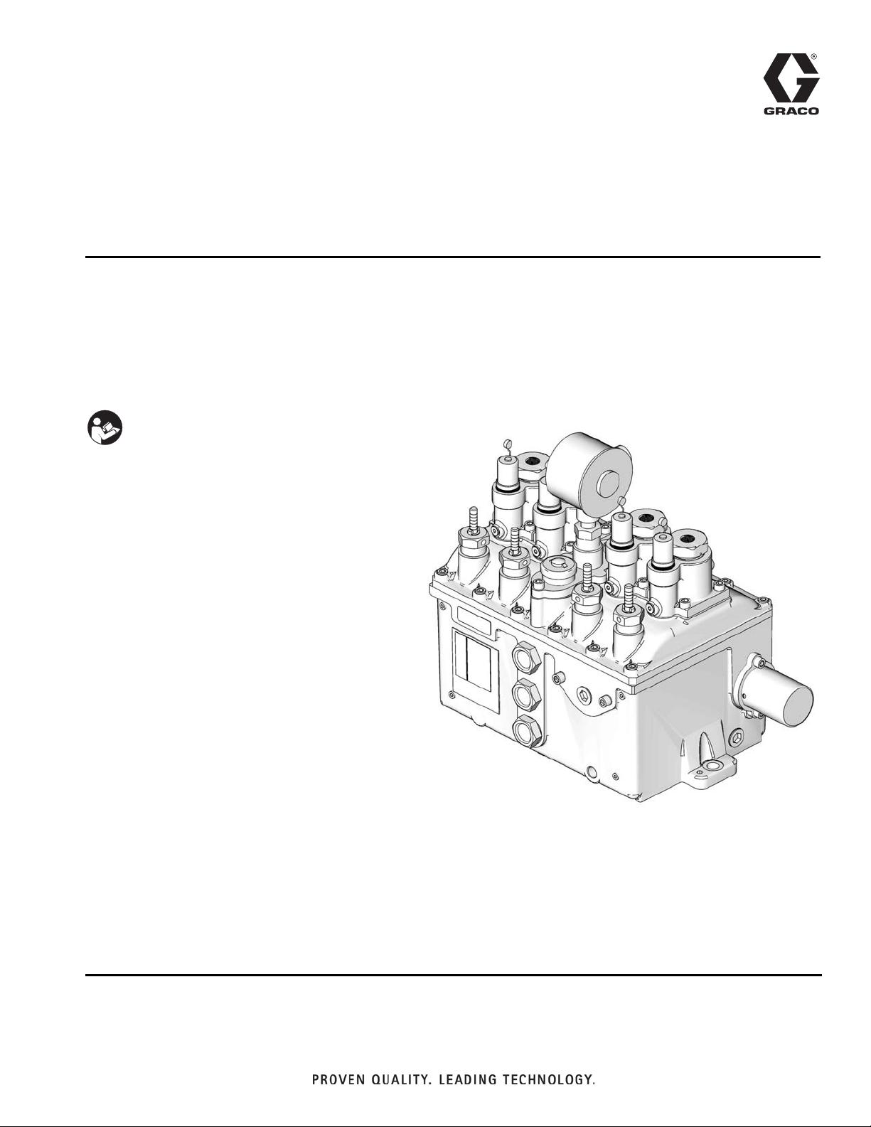
Operation/Service/Parts
HP50 High Pressure
311842C
Bulletin 40240/51030
Lubricators
For dispensing non-corrosive and non-abrasive oils and synthetic-based lubricants.
Models: 258262, 258263, 562925, 562926, 562927, 562928, 562929, 564276,
564277, 564278, 564279, 564280, 564281, 564282, 564284
HP50: 50,000 psi (344 MPa, 3,447 bar) Maximum Working Pressure
Important Safety Instructions
Read all warnings and instructions in this
manual. Save these instructions.
EN
ti13802
TI8512
Page 2
Warnings
Warnings
The following warnings are for the setup, use, grounding, maintenance, and repair of this equipment. The exclamation point symbol alerts you to a general warning and the hazard symbol refers to procedure-specific risk. Refer back
to these warnings. Additional, product-specific warnings may be found throughout the body of this manual where
applicable.
WARNING
FIRE AND EXPLOSION HAZARD
When flammable fluids are present in the work area, such as gasoline and windshield wiper fluid, be
aware that flammable fumes can ignite or explode. To help prevent fire and explosion:
• Use equipment only in well ventilated area.
• Eliminate all ignition sources, such as cigarettes and portable electric lamps.
• Keep work area free of debris, including rags and spilled or open containers of solvent and gasoline.
• Do not plug or unplug power cords or turn lights on or off when flammable fumes are present.
• Ground all equipment in the work area.
• Use only grounded hoses.
• If there is static sparking or you feel a shock, stop operation immediately. Do not use equipment
until you identify and correct the problem.
• Keep a working fire extinguisher in the work area.
EQUIPMENT MISUSE HAZARD
Misuse can cause death or serious injury.
• Do not operate the unit when fatigued or under the influence of drugs or alcohol.
• Do not exceed the maximum working pressure or temperature rating of the lowest rated system
component. See Technical Data in all equipment manuals.
• Use fluids and solvents that are compatible with equipment wetted parts. See Technical Data in all
equipment manuals. Read fluid and solvent manufacturer’s warnings. For complete information
about your material, request MSDS forms from distributor or retailer.
• Check equipment daily. Repair or replace worn or damaged parts immediately with genuine manufacturer’s replacement parts only.
• Do not alter or modify equipment.
• Use equipment only for its intended purpose. Call your distributor for information.
• Route hoses and cables away from traffic areas, sharp edges, moving parts, and hot surfaces.
• Do not kink or over bend hoses or use hoses to pull equipment.
• Keep children and animals away from work area.
• Comply with all applicable safety regulations.
ELECTRIC SHOCK HAZARD
Improper grounding, setup, or usage of the system can cause electric shock.
• Turn off and disconnect power at main switch before disconnecting any cables and before servicing
equipment.
• Connect only to grounded power source.
• All electrical wiring must be done by a qualified electrician and comply with all local codes and
regulations.
2 311842C
Page 3
Warnings
WARNING
SKIN INJECTION HAZARD
High-pressure fluid from dispense valve, hose leaks, or ruptured components will pierce skin. This may
look like just a cut, but it is a serious injury that can result in amputation. Get immediate surgical
treatment.
• Do not point dispense valve at anyone or at any part of the body.
• Do not put your hand over the end of the dispense nozzle.
• Do not stop or deflect leaks with your hand, body, glove, or rag.
• Follow Pressure Relief Procedure in this manual, when you stop dispensing and before cleaning,
checking, or servicing equipment.
MOVING PARTS HAZARD
Moving parts can pinch or amputate fingers and other body parts.
• Keep clear of moving parts.
• Do not operate equipment with protective guards or covers removed.
• Pressurized equipment can start without warning. Before checking, moving, or servicing equipment,
follow the Pressure Relief Procedure in this manual. Disconnect power or air supply.
SUCTION HAZARD
Never place hands near the pump fluid inlet when pump is operating or pressurized. Powerful suction
could cause serious injury.
BURN HAZARD
Equipment surfaces and fluid that’s heated can become very hot during operation. To avoid severe
burns, do not touch hot fluid or equipment. Wait until equipment/fluid has cooled completely.
PERSONAL PROTECTIVE EQUIPMENT
You must wear appropriate protective equipment when operating, servicing, or when in the operating
area of the equipment to help protect you from serious injury, including eye injury, inhalation of toxic
fumes, burns, and hearing loss. This equipment includes but is not limited to:
• Protective eyewear
• Clothing and respirator as recommended by the fluid and solvent manufacturer
•Gloves
• Hearing protection
311842C 3
Page 4
Installation
Installation
NOTICE
All installation, maintenance, and repair work must
be completed by qualified personnel.
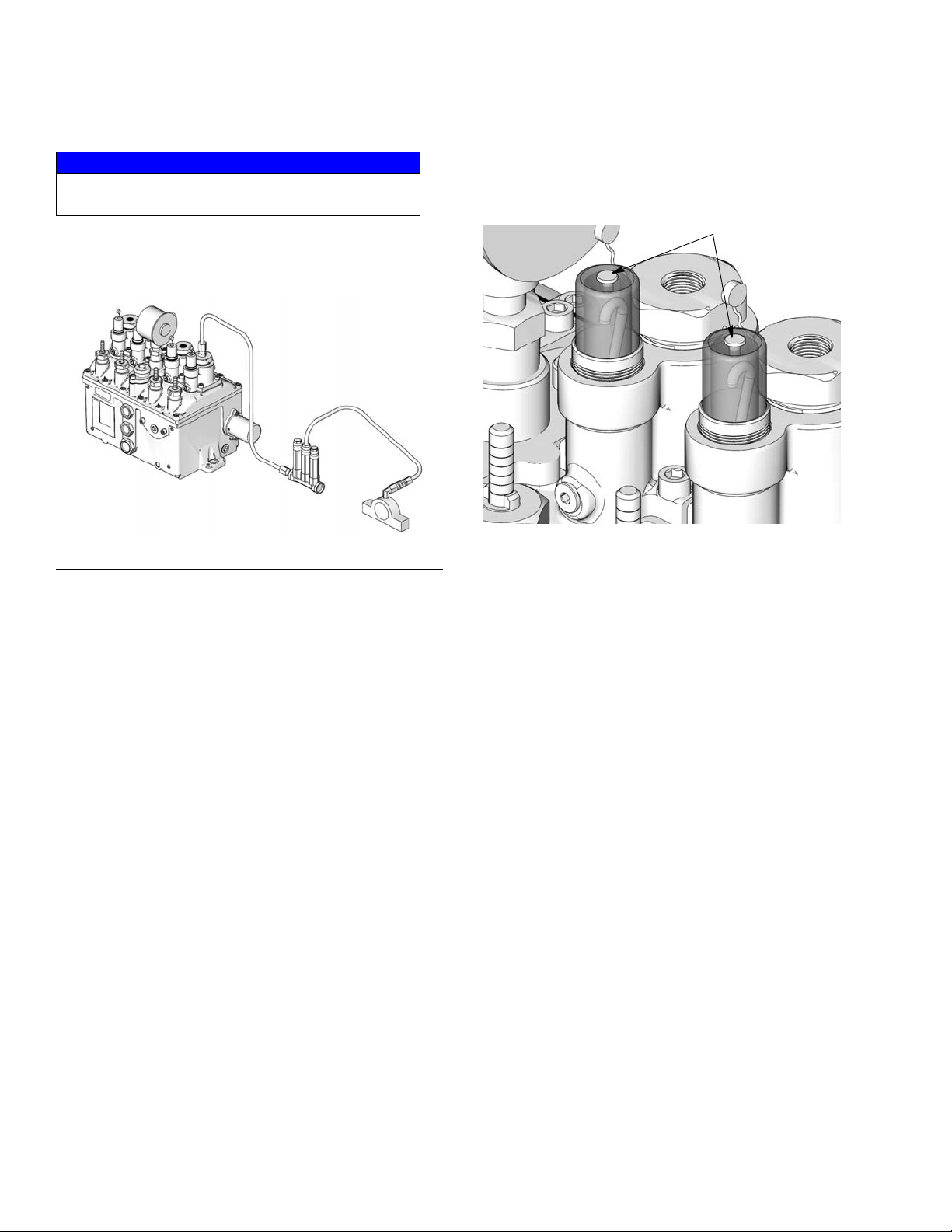
System Connections
ti13803
F
IG. 1
Operation
Oil Level
A
ti13804
FIG. 2
• Install each pumping unit with a high pressure check
valve in the discharge line adjacent to the pump discharge connection so that pump assembly may be
removed from reservoir without loss of lubricant in
lines (F
• Install a second of these valves at the point of lubrication to prevent line drainage and feedback of system pressure to pump (F
IG. 1).
IG. 1).
1. Remove vent plugs (A) located on the top of the
pump sight glasses to allow lubricant to rise in the
drip tube to the level of the oil in the reservoir and
reduce the priming required at start up (F
2. Completely fill the lubricator reservoir with clean filtered lubricant.
IG. 2).
4 311842C
Page 5
Operation
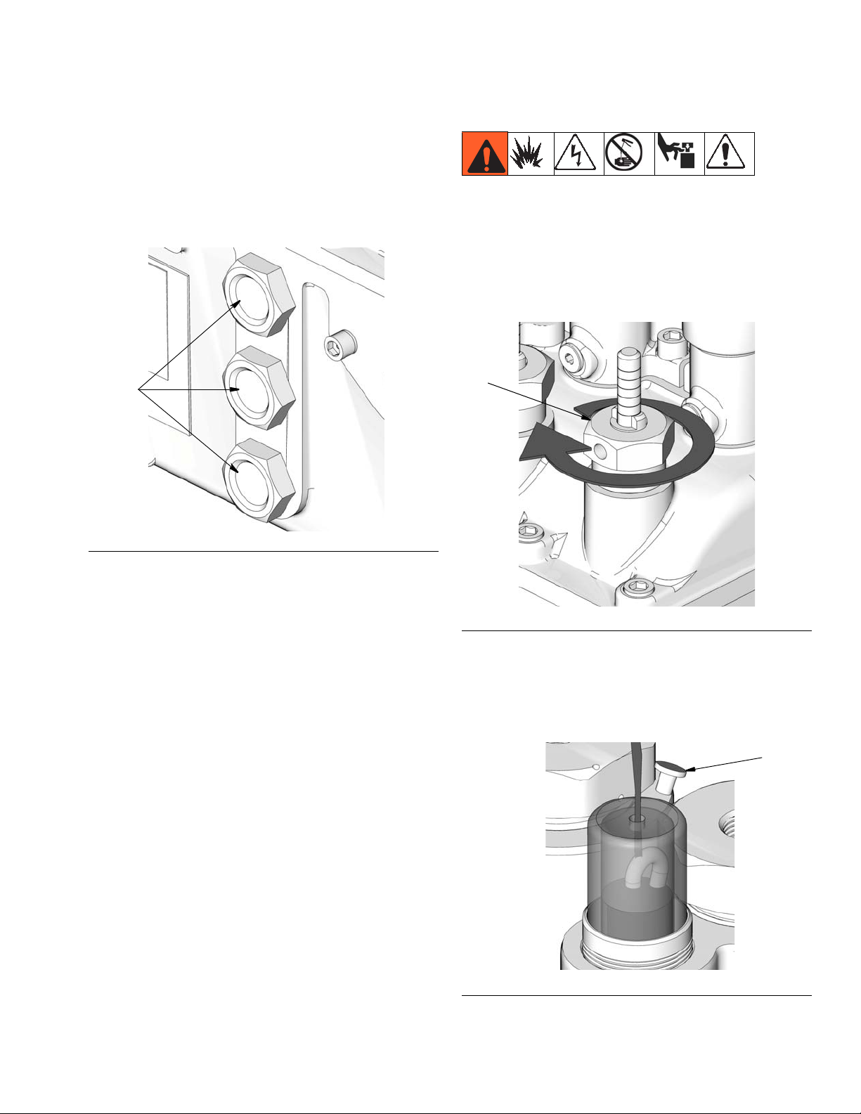
NOTE:
• Three sight glasses (B) are provided in the reservoir at various levels to permit observation of
fluid level (F
IG. 3).
• Oil level should not be allowed to drop below the
bottom sight glass.
B
ti13805
Pump Priming
To prime the pump:
1. Turn the feed adjustment nut (C) on the indicator
stem as far as possible in a clockwise direction (F
4).
C
IG.
F
IG. 3
ti13806
FIG. 4
2. Remove the vent plug (A) on top of the sight glass
and fill the housing sight well with oil to 3/8-inch
below the discharge of the drip tube (F
IG. 5).
A
ti13708
F
IG. 5
311842C 5
Page 6

Operation
3. Replace the vent plug (A). Check the sight glass to
insure that it is properly seated against the o-ring
(D) to prevent air leakage into the sight well (F
IG. 6).
A
D
ti13709
F
IG. 6
4. Adjust the pumping rate to the desired delivery.
Pumping Rate
During the pump suction stroke an amount of oil equal
to the pump displacement is drawn through the drip tube
into the sight well. The amount of fluid in the site tube
indicates the pumping rate.
NOTE: Allow sufficient time to insure an accurate rate
indication. The drip tube flow rate is only accurate after
the pump has operated long enough to stabilize the
pressure inside the sight well.
C
F
IG. 7
• Turn the feed adjustment nut (C) counter-clockwise
to reduce the pump stroke and delivery (F
IG. 8).
C
F
There is a time lag at start-up, during low pumping rates,
IG. 8
and during pump rate changes.
Regulating Pump Rate
The pumping rate is adjusted by hand during the pump
suction stroke.
• Turn feed adjustment nut (C) clockwise as far as it
can go to achieve maximum pumping rate (F
6 311842C
IG. 7.
Page 7

Service
Pressure Relief Procedure
The equipment stays pressurized until pressure is
relieved. To reduce the risk of serious injury from pressurized fluid, accidental spray from the dispenser, or
splashing fluid, follow this Pressure Relief Procedure
whenever you:
• Check, clean or service any system equipment.
• Install or clean fluid nozzles.
1. Disconnect power supply.
2. Open any bleed-type master air valves and fluid
drain valves in the system.
Service
A
3. Leave drain valves open until you have completed
repairs and are ready to pressurize system.
NOTICE
• All installation, maintenance, and repair work
must be completed by qualified personnel.
• If the correct pumping rate is maintained, no service is required other than periodic replenishment of the reservoir.
Service Instructions
1. Check lubricator operation by observing the drip
tube. If the sight glass well pumps dry or no flow is
observed, check the following points until the cause
is determined and corrected.
• Check the vent plug (A) for proper sealing. Any
knicks or cracks in the rubber plug will cause an
air leak into the sight glass (F
IG. 9).
FIG. 9
• Check shaft rotation. If the lubricator shaft is not
rotating, determine the cause and repair as necessary.
• Check oil level and viscosity. Be sure the reservoir is filled with oil, and if necessary heat the
reservoir to maintain viscosity at the correct
level for the desired flow.
• Check pump priming. If necessary, prime the
pump in accordance with the operating instructions, page 5.
• Check the feed adjustment (C, F
page 6) and adjust if the pumping rate is too
low.
IG. 7 and FIG. 8,
• Check the actuating linkage for proper operation. If defective, isolate the broken part and
repair or replace as required.
311842C 7
Page 8

Service
‘
2. If items listed in step 1 are not the cause, check the
pump assembly. The following items should be
checked before removing the pump assembly from
the cover.
• Check the sight glass for inward leakage due to
a crack in the sight glass, improper sight glass
seating, or a defective o-ring. Repair as
required (F
IG. 6, page 6).
• Check for an obstruction in the drip tube and
remove if found.
• If these steps do not isolate the malfunction:
a. Relieve system pressure, page 7.
b. Disconnect the discharge tubing (E) (F
c. Remove 4 screws (F) holding pump to cover
IG. 10).
(F
d. Remove the pump assembly (G) (F
NOTE:
• Keep a spare pump on hand for use during
emergencies and when the pump is being
repaired.
• If a spare pump is available, it will not be necessary to stop the equipment the lubricator is
installed on or to empty the reservoir.
IG. 10).
IG. 10).
A
MOVING PARTS HAZARD
Exercise extreme care if equipment is operating.
Rotating equipment can cause serious injury.
E
F
G
F
IG. 10
IG. 11
F
• If the sight glass fills with lubricant proceed as
follows:
a. Remove system pressure, page 7.
b. Remove vent plug (A) (F
IG. 11).
c. Allow the lubricant to pump down to the
proper level.
8 311842C
Page 9

Service
d. Replace vent plug (A).
The pump should operate normally.
• If the sight glass continues to fill with lubricant:
a. Check all terminal check valves for proper
operation.
b. Relieve system pressure, page 7.
c. If valves are operating properly, disconnect
the discharge tubing (E) (F
IG. 10)
d. Remove 4 screws holding pump to cover
(F
IG. 10, page 8).
e. Remove pump assembly.
f. Clean pump assembly.
g. Reinstall pump assembly to cover and check
operation.
• When the unit is operating the sight level will
vary depending on temperature variations.
a. If the level falls to less than 1/4 inch above
the sight glass flange, add lubricant to the
proper level (3/8 inch below the discharge of
the drip tube) through the vent hole.
b. If the level is too high, remove the vent plug
and allow the unit to pump down before
replacing the vent plug.
Other servicing that may be required is listed below:
• Clean lubricator periodically to eliminate contamination that may have occurred in the oil. To accomplish
this, remove all pumping units and clean the pumps
and reservoir by brushing loose all foreign matter,
dipping in solvent and blowing dry with compressed
air.
• If external leakage is observed, determine the
cause (loose bolts, defective gaskets, or seals) and
repair as required.
3. If the sight glass still fills with lubricant it may be
caused by temperature variation.
• When the unit is not operating:
a. Relieve system pressure, page 7.
b. Remove vent plug (F
IG. 11, page 8).
c. Allow lubricant to pump down to the proper
level.
d. Replace vent plug.
The pump will now function properly. The
sight glass may fill with fluid without affecting
the operation of the lubricator as long as the
drip tube remains above the lubricant level to
show the rate of pumping.
311842C 9
Page 10

High Pressure Lubricator Parts
High Pressure Lubricator Parts
44
45
43
12
1
17
16
25
46
42
4
40
41
13
14
27
15
30
24
23
20
18
9
Ref Part No. Description Qty
1 556340 BEARING, ecc shaft 2
2 556343 BEARING, slv, bronze 2
3 560148 BUSHING, reservoir 2
4 560157 NUT, fluid adjustment 4
5 560169 PIN, lever 4
7 560171 PIN, adjustment rod 4
8 555444 PLUG, 3/8” pipe square head 1
9 555450 PLUG, 3/4” pipe hex soc 3
10 556450 PLUG, hex-sckt 1 1/4 npt 1
11 555552 RING, retainer 8
12 555603 SCREW, 3/8-16 X .75 soc hd cap 4
13 555605 SCREW, 3/8-16 X 1.25 soc hd cap 26
14 555606 SCREW, 3/8-16 X 3.50 soc hd cap 4
15 556523 WASHER, copper 1.0 id 4
16 555664 O-RING ,-228 buna-n 70 duro 2
17 556579 SEAL,LIP 1.25 ID 2.00 OD .25 W 2
18 556683 SIGHTGLASS 3
20 556685 PLATE, oil level 3
21 560281 ROD, fluid adjusment 4
28
22
12
2
21
8
31
32
47
5
11
7
3
17
9
39
26
16
10
2
1
12
Ref Part No. Description Qty
22 560284 LEVER, pump 4
23 556836 LABEL, operating instructions 1
24 556872 LABEL, identification 1
25 557062 SHAFT, crank 1
26 15M340 RESERVOIR 1
27 560398 COVER, reservoir 1
28 560483 LEVER, shoe 4
29 562952 PUMP (page 11) 4
30 555379 KEY 2
31 110208 PLUG, pipe, headless 4
32 15W154 WASHER 2
36 555451 PLUG, steel 1
37 563024 SWITCH, low level exp proof (not
shown)
38 557122 COVER, shaft end 1
39 555483 SCREW, #4 X .187 pan head self
tap
40 556745 GASKET 1
41 563090 PLATE, filler 1
38
1
2
10 311842C
Page 11

Ref Part No. Description Qty
42 557149 STRAINER, filter 2
43 557171 COVER, oil hole 1
44 557391 PLUG, dryseal, 1/4 nptf 1
45 555451 PLUG, pipe 1
46 556517 SCREW, socket head 3/8 x 15 x
0.875
47 555424 PIN, 0.312 Diameter groove type
2A
Pump Parts
Ref Part No. Description Qty
101 560162 NUT 1
102 560172 PIN, collar 1
103 555564 RING, retainer 1
104 560195 RING, retaining spring 1
105 556522 DISK, thrust 1
106 555691 O-RING, -127 1
107 555694 O-RING, -217 1
108 560233 SPACER, .995 id x .500 long 1
109 560235 TUBE, drip 1
110 562989 TUBE, suction 1
111 555724 PLUG, #4 SAE 1
112 564151 KIT, sight glass 1
113 556746 GASKET, suction tube nut 1
114 556747 O-RING 2
115 555746 SEAL, wire lead .437 diameter 1
116 556936 SPRING, check valve 1
117 556937 SPRING, plunger 1
118 560340 SEAT, valve 1
119 560344 VALVE, 1
120 557155 STRAINER, suction 1
122 560425 PLUNGER, pusher 1
123 563111 VALVE, plunger 1
124 560443 HOUSING, pump 1
125 557191 COLLAR, piston 1
126 560492 COLLAR 1
High Pressure Lubricator Parts
1
2
115
112
109
111
119
126
106
113
101
124
116
118
114
123
107
103
125
108
117
110
120
311842C 11
105
104
102
122
Page 12

High Pressure Lubricator Parts
Check Valve Parts Drawing and Parts List
564335 - Discharge check valve
564336 - Terminal check valve
1
2
Tubing furnished
by customer
9*
1
2
8
1*
2*
*Supplied with Discharge Check Valve 564335 only.
Not supplied with Terminal Check Valves.
5
6
4
7
564335 Discharge Check Valve - 3/8” OD Tube 564336 Terminal Check Valve
Ref. Part No. Description Qty.
1 556783 NUT, Gland 3
2 556781 COLLAR 3
4 556936 SPRING, Valve 1
5 560343 VALVE 1
6 560339 SEAT, Valve 1
8 561354 BODY, Check Valve 1
9 558823 NIPPLE, Check Valve 1
10 560161 NUT 2
Ref. Part No. Description Qty.
1 556783 NUT, Gland 2
2 556781 COLLAR 2
4 556936 SPRING, Valve 1
5 560343 VALVE 1
6 560339 SEAT, Valve 1
8 561354 BODY, Check Valve 1
10 560161 NUT 2
11 556747 O-RING 2
11 556747 O-RING 2
TI8477
Steam Heater Parts Drawing and Parts List
3
4
2
Ref. Part No. Description Qty.
1 558792 ELBOW, 1/4 NPT Steam Pipe 2
2 561335 SEAL PLUG, Steam Pipe 2
3 558693 SEAL, Steam Pipe 2
4 560179 STEAM PIPE 1
12 311842C
1
TI8478
Page 13

Technical Data
Technical Data
Plunger Diameter 1/4 in. (0.64 cm)
HP-50 Maximum Operating Pressure 50,000 psi (344 MPa, 3,447 bar)
Reservoir Capacity 9 quarts (8.5 liters) from centerline of top gauge
glass to centerline of bottom gauge glass
Maximum Pumping Rate based on SAE 40 oil — (approx. 4 drops)
Minimum Pump Rate
Reservoir Heating (optional) Steam or Electric
Lubricant Viscosity 100 to 5000 SUS
Operating Temperature -200°F to 1200°F (-129°C to 649°C)
0.008 in
0.001 in
3
(0.133 cc) per stroke
3
(0.017 cc) at max. pressure
LUBRICATOR CHARACTERISTICS
Model Number of
Feeds
HP-50 1 to 4 50,000 9 1/4 4 1 0.008 0.002 0.133 0.033 36 3
† Usable reservoir capacity, as measured from centerline of top gauge glass to centerline of bottom gauge glass
(see page 10).
‡ All displacements are based on SAE 30 oil (500 S.U.S. at 100°F.) at room temperature. Volumetric equivalents of
drops are: 14,115 drops equal 1 pint, 490 drops equal 1 cu. in., 30 drops equal 1 cc.
Maximum
Operating
Pressure
Reservoir
Capacity
(Quarts)†
Plunger
Diameter
(Inches)
Drops /
Stroke
Max. Min. Max. Min. Max. Min. Max. Min.
Pumping Unit Displacements‡
cu. in. /
Stroke
cc / Stroke Strokes / min.
Construction Materials
Reservoir and Cover - Heavily ribbed cast iron.
Cylinder - Hardened alloy steel, precision-honed.
Plunger - Hardened alloy steel, precision-ground and
fitted.
Valves - Poppet type, flat face, hardened and ground
alloy steel.
Valve Seats - Hardened and ground alloy steel.
Driveshaft - Integral crankshaft type, hardened, ground
and polished alloy steel, machined from solid bar.
Bearings - Bronze bushed, high load capacity, long-life,
self-lubricating type.
Regulating Lever - Forged steel.
311842C 13
Page 14

Dimensions
Dimensions
7.68 in
(19. 5 cm)
4.125 in.
(10.4 cm)
3.125 in.
(
7.93 cm)
2.75 in.
(6.98 cm)
11.75 in.
(29.84 cm)
14.765 in.
(37.5 cm)
13.5 in.
(34.29 cm)
16.625 in. (42.22 cm)
22.68 in. (57.6 cm)
TI8514
11.56 in (29.36 cm)
14 311842C
Page 15

NOTES
NOTES
311842C 15
Page 16

Graco Standard Warranty
Graco warrants all equipment referenced in this document which is manufactured by Graco and bearing its name to be free from defects in
material and workmanship on the date of sale to the original purchaser for use. With the exception of any special, extended, or limited warranty
published by Graco, Graco will, for a period of twelve months from the date of sale, repair or replace any part of the equipment determined by
Graco to be defective. This warranty applies only when the equipment is installed, operated and maintained in accordance with Graco’s written
recommendations.
This warranty does not cover, and Graco shall not be liable for general wear and tear, or any malfunction, damage or wear caused by faulty
installation, misapplication, abrasion, corrosion, inadequate or improper maintenance, negligence, accident, tampering, or substitution of
non-Graco component parts. Nor shall Graco be liable for malfunction, damage or wear caused by the incompatibility of Graco equipment with
structures, accessories, equipment or materials not supplied by Graco, or the improper design, manufacture, installation, operation or
maintenance of structures, accessories, equipment or materials not supplied by Graco.
This warranty is conditioned upon the prepaid return of the equipment claimed to be defective to an authorized Graco distributor for verification of
the claimed defect. If the claimed defect is verified, Graco will repair or replace free of charge any defective parts. The equipment will be returned
to the original purchaser transportation prepaid. If inspection of the equipment does not disclose any defect in material or workmanship, repairs will
be made at a reasonable charge, which charges may include the costs of parts, labor, and transportation.
THIS WARRANTY IS EXCLUSIVE, AND IS IN LIEU OF ANY OTHER WARRANTIES, EXPRESS OR IMPLIED, INCLUDING BUT NOT LIMITED
TO WARRANTY OF MERCHANTABILITY OR WARRANTY OF FITNESS FOR A PARTICULAR PURPOSE.
Graco’s sole obligation and buyer’s sole remedy for any breach of warranty shall be as set forth above. The buyer agrees that no other remedy
(including, but not limited to, incidental or consequential damages for lost profits, lost sales, injury to person or property, or any other incidental or
consequential loss) shall be available. Any action for breach of warranty must be brought within two (2) years of the date of sale.
GRACO MAKES NO WARRANTY, AND DISCLAIMS ALL IMPLIED WARRANTIES OF MERCHANTABILITY AND FITNESS FOR A
PARTICULAR PURPOSE, IN CONNECTION WITH ACCESSORIES, EQUIPMENT, MATERIALS OR COMPONENTS SOLD BUT NOT
MANUFACTURED BY GRACO. These items sold, but not manufactured by Graco (such as electric motors, switches, hose, etc.), are subject to
the warranty, if any, of their manufacturer. Graco will provide purchaser with reasonable assistance in making any claim for breach of these
warranties.
In no event will Graco be liable for indirect, incidental, special or consequential damages resulting from Graco supplying equipment hereunder, or
the furnishing, performance, or use of any products or other goods sold hereto, whether due to a breach of contract, breach of warranty, the
negligence of Graco, or otherwise.
FOR GRACO CANADA CUSTOMERS
The Parties acknowledge that they have required that the present document, as well as all documents, notices and legal proceedings entered into,
given or instituted pursuant hereto or relating directly or indirectly hereto, be drawn up in English. Les parties reconnaissent avoir convenu que la
rédaction du présente document sera en Anglais, ainsi que tous documents, avis et procédures judiciaires exécutés, donnés ou intentés, à la suite
de ou en rapport, directement ou indirectement, avec les procédures concernées.
Graco Information
TO PLACE AN ORDER, contact your Graco distributor or call to identify the nearest distributor.
Phone: 612-623-6928 or Toll Free: 1-800-533-9655, Fax: 612-378-3590
All written and visual data contained in this document reflects the latest product information available at the time of publication.
GRACO INC. AND SUBSIDIARIES • P.O. BOX 1441 • MINNEAPOLIS MN 55440-1441 • USA
Copyright 2007, Graco Inc. All Graco manufacturing locations are registered to ISO 9001.
Graco reserves the right to make changes at any time without notice.
For patent information, see www.graco.com/patents.
Original instructions. This manual contains English. MM 311842
Graco Headquarters: Minneapolis
International Offices: Belgium, China, Japan, Korea
www.graco.com
Revised April 2012
 Loading...