

Page 1
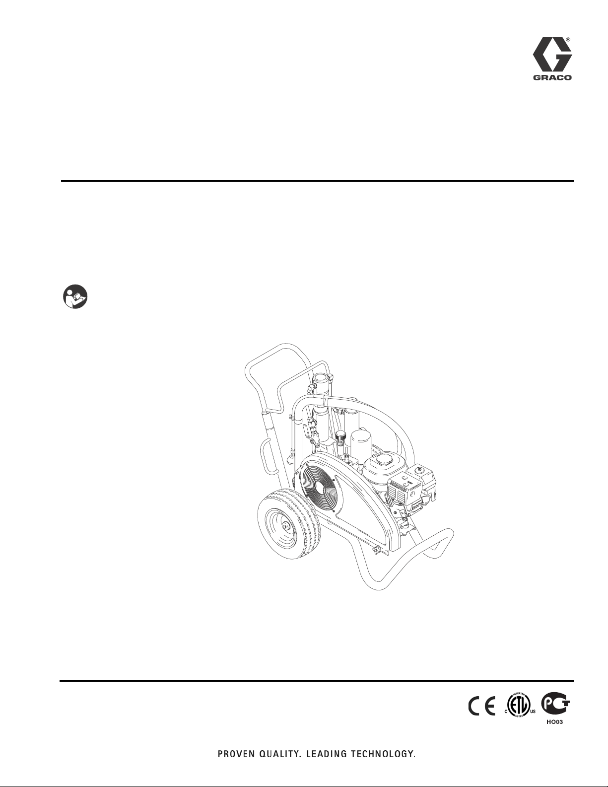
Repair
GH™ 130, GH 200,
GH 230, GH 300
Hydraulic Sprayers
- Use with Architectural Coatings and Paints -
3300 psi (2.8 MPa, 228 bar) Maximum Working Pressure
List of models provided on page 2.
IMPORTANT SAFETY INSTRUCTIONS.
Read all warnings and instructions in this manual. Save these instructions. Contact
Graco Customer Service, your local Graco distributor or our website:
www.graco.com, to obtain a manual in your language.
311797J
ENG
ti5380a
Page 2
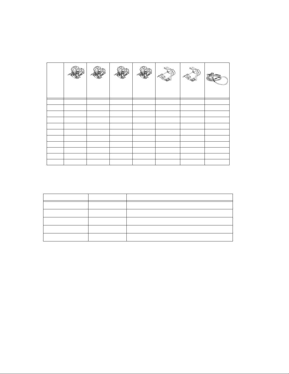
Models
Models
GH130 GH200 GH230 GH300
253957
253959
253980
253962
253963
253981
255095
253965
253966
253982
253968
✔✔
✔✔✔
✔✔✔
✔✔
✔✔✔
✔✔✔
✔✔
Electric Motor Kit Options
Kit Number Sprayer Model Description
288474
288473
248950
248949
248946
GH130 120VAC, 60Hz, 20A, CAS/UL approved
GH130 120VAC, 60Hz, 15A
GH200/GH230 120VAC, 60Hz, 20A, CSA/UL approved
GH200/GH230 120 VAC, 60Hz, 15A
EH200/HD1200 240VAC, 50Hz, 13.4A
120 Vac
60 Hz
ETL/CSA/UL
120 Vac
60 Hz
✔✔
✔✔ ✔
✔✔✔
✔✔
2 311797J
Page 3
Models
Warnings
The following Warnings are for the setup, use, grounding, maintenance and repair of this equipment. The exclamation point symbol alerts you to a general warning and the hazard symbols refer to procedure-specific risks. Refer
back to these Warnings. Additional, product-specific warnings may be found throughout the body of this manual
where applicable.
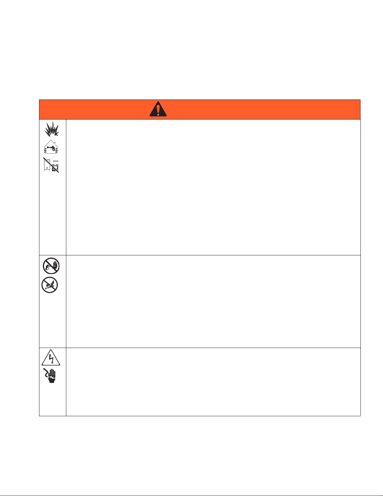
WARNING
WARNINGWARNINGWARNING
FIRE AND EXPLOSION HAZARD
Flammable fumes, such as solvent and paint fumes, in work area can ignite or explode. To help prevent
fire and explosion:
• Use equipment only in well ventilated area.
• Eliminate all ignition sources; such as pilot lights, cigarettes, portable electric lamps, and plastic drop
cloths (potential static arc).
• Keep work area free of debris, including solvent, rags and gasoline.
• Do not plug or unplug power cords, or turn power or light switches on or off when flammable fumes are
present.
• Ground all equipment in the work area. See Grounding instructions.
• Use only grounded hoses.
• Hold gun firmly to side of grounded pail when triggering into pail.
• If there is static sparking or you feel a shock, stop operation immediately. Do not use equipment until
you identify and correct the problem.
• Keep a working fire extinguisher in the work area.
SKIN INJECTION HAZARD
High-pressure fluid from gun, hose leaks, or ruptured components will pierce skin. This may look like just
a cut, but it is a serious injury that can result in amputation. Get immediate surgical treatment.
• Do not point gun at anyone or at any part of the body.
• Do not put your hand over the spray tip.
• Do not stop or deflect leaks with your hand, body, glove, or rag.
• Do not spray without tip guard and trigger guard installed.
• Engage trigger lock when not spraying.
• Follow Pressure Relief Procedure in this manual, when you stop spraying and before cleaning,
checking, or servicing equipment.
ELECTRIC SHOCK HAZARD
Improper grounding, setup, or usage of the system can cause electric shock.
• Turn off and disconnect power cord before servicing equipment.
• Use only grounded electrical outlets.
• Use only 3-wire extension cords.
• Ensure ground prongs are intact on sprayer and extension cords.
• Do not expose to rain. Store indoors.
311797J 3
Page 4
Models
WARNING
WARNINGWARNINGWARNING
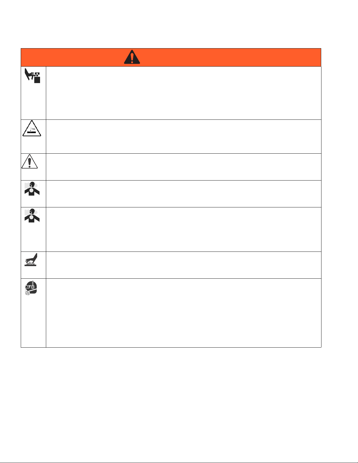
MOVING PARTS HAZARD
Moving parts can pinch or amputate fingers and other body parts.
• Keep clear of moving parts.
• Do not operate equipment with protective guards or covers removed.
• Pressurized equipment can start without warning. Before checking, moving, or servicing equipment,
follow the Pressure Relief Procedure in this manual. Disconnect power or air supply.
PRESSURIZED ALUMINUM PARTS HAZARD
Do not use 1,1,1-trichloroethane, methylene chloride, other halogenated hydrocarbon solvents or fluids
containing such solvents in pressurized aluminum equipment. Such use can cause serious chemical
reaction and equipment rupture, and result in death, serious injury, and property damage.
SUCTION HAZARD
Never place hands near the pump fluid inlet when pump is operating or pressurized. Powerful suction
could cause serious injury.
CARBON MONOXIDE HAZARD
Exhaust contains poisonous carbon monoxide, which is colorless and odorless. Breathing carbon
monoxide can cause death. Do not operate in an enclosed area.
TOXIC FLUID OR FUMES HAZARD
Toxic fluids or fumes can cause serious injury or death if splashed in the eyes or on skin, inhaled, or
swallowed.
• Read MSDS’s to know the specific hazards of the fluids you are using.
• Store hazardous fluid in approved containers, and dispose of it according to applicable guidelines.
BURN HAZARD
Equipment surfaces and fluid that’s heated can become very hot during operation. To avoid severe burns,
do not touch hot fluid or equipment. Wait until equipment/fluid has cooled completely.
PERSONAL PROTECTIVE EQUIPMENT
You must wear appropriate protective equipment when operating, servicing, or when in the operating area
of the equipment to help protect you from serious injury, including eye injury, inhalation of toxic fumes,
burns, and hearing loss. This equipment includes but is not limited to:
• Protective eyewear
• Clothing and respirator as recommended by the fluid and solvent manufacturer
•Gloves
• Hearing protection
4 311797J
Page 5
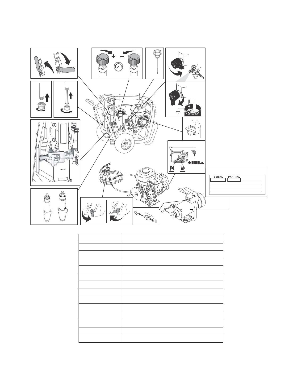
Component Identification
Component Identification
1.
10.
on
ti9126a
2.
3.
4.
off
bar/MPa
PSI
ti9167a
11.12.
ti8714a
5.
OFF
ON
ti9166a
6.
13.
ti8691a
9.
ti8844a
8.
7.
Item No. Component
1 Hydraulic pump valve
2 Pressure control
3 Hydraulic Oil Cap
4Drain valve
5 Engine ON/OFF switch
6 Engine controls
7 Electric motor On/Off Switch
8 Gun trigger Lock
9 Displacement pump
10
11 Inlet strainer (standard)
12 Inlet strainer (option)
13 Serial number tag
ProConnect
ti5381b
™
311797J 5
Page 6
General Repair Information
General Repair Information
To reduce risk of serious injury, do not touch moving
parts with fingers or tools while testing repair. Shut
off sprayer when repairing. Install all covers,
gaskets, screws and washers before operating
sprayer
1 Keep all screws, nuts, washers, gaskets, and electrical
fittings removed during repair procedures. These parts
are not normally provided with replacement assemblies.
2 Test repair after problem is corrected.
3 If sprayer does not operate properly, review repair
procedure to verify procedure was done correctly. If
necessary, see Troubleshooting Guide, page 7, for other
possible solutions.
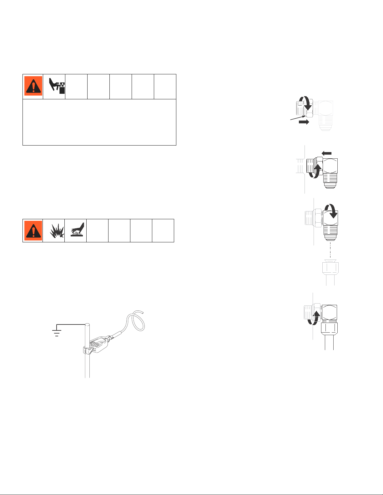
SAE O-Ring Installation
1 Unscrew lock nut to touch fitting.
2 Lubricate o-ring (A).
3 Screw in fitting hand tight.
4 Unscrew fitting until oriented
properly.
A
ti5415a
ti5414a
4 Install belt guard before operation of sprayer and replace
if damaged. Belt guard reduces risk of pinching and loss
of fingers; see preceding WARNING.
Grounding
Ground sprayer with grounding clamp to earth ground
for safe sprayer operation when using solvent-based
materials. Fig. 1.
6250
F
IG. 1
ti5416a
5 Tighten lock nut to indicated torque.
(Make sure washer is seated properly
without pinching o-ring).
ti5417a
6 311797J
Page 7

Maintenance
Pressure Relief Procedure
The system pressure must be manually relieved to
prevent the system from starting or spraying
accidentally. Fluid under high pressure can be injected
through the skin and cause serious injury. To reduce
the risk of an injury from injection, splashing fluid, or
moving parts, follow the Pressure Relief Procedure
whenever you:
• are instructed to relieve the pressure,
• stop spraying,
• check or service any of the system equipment,
• or install or clean the spray tip.
1 Lock gun trigger safety.
2 Turn engine ON/OFF switch to OFF.
3 Move pump valve to OFF (down) and turn pressure
control knob fully counter clockwise.
4 Unlock trigger safety. Hold metal part of gun firmly to side
of grounded metal pail, and trigger gun to relieve
pressure.
5 Lock gun trigger safety.
6 Open pressure drain valve. Leave valve open until ready
to spray again.
If you suspect that the spray tip or hose is completely
clogged, or that pressure has not been fully relieved
after following the steps above, VERY SLOWLY loosen
tip guard retaining nut or hose end coupling to relieve
pressure gradually, then loosen completely. Now clear
tip or hose.
NOTICE
For detailed engine maintenance and specifications,
refer to separate Honda Engines Owner's Manual,
supplied.
Maintenance
DAILY: Check and fill the gas tank.
DAILY: Check that displacement pump is tight.
DAILY: Check level of Throat Seal Liquid (TSL) in dis-
placement pump packing nut. Fill nut, if necessary. Keep
TSL in nut to help prevent fluid buildup on piston rod and
premature wear of packings and pump corrosion.
AFTER THE FIRST 20 HOURS OF OPERATION:
Drain engine oil and refill with clean oil. Reference
Honda Engines Owner's Manual for correct oil viscosity.
WEEKLY: Remove engine air filter cover and clean element. Replace element, if necessary. If operating in an
unusually dusty environment: check filter daily and
replace, if necessary.
Replacement elements can be purchased from your
local HONDA dealer.
W EE KLY / DA ILY: Remove any debris or media from
hydraulic rod.
AFTER EACH 100 HOURS OF OPERATION:
Change engine oil. Reference Honda Engines Owner's
Manual for correct oil viscosity.
SEMI-ANNUALLY:
Check belt wear, page 10; replace if necessary.
YEARLY OR 2000 HOURS:
Replace hydraulic oil and filter with Graco hydraulic oil
169236 (5 gallon/20 liter) or 207428 (1 gallon/3.8 liter)
and filter 116909.
Replace belt.
DAILY: Check engine oil level and fill as necessary.
DAILY: Check hydraulic oil level and fill as necessary.
DAILY: Check hose for wear and damage.
DAILY: Check gun safety for proper operation.
DAILY: Check pressure drain valve for proper operation.
311797J 7
SPARK PLUG: Use only BPR6ES (NGK) or W20EPR-U
(NIPPONDENSO) plug. Gap plug to 0.028 to 0.031 in.
(0.7 to 0.8 mm). Use spark plug wrench when installing
and removing plug.
Page 8

Troubleshooting
Troubleshooting
PROBLEM CAUSE SOLUTION
Gas engine pulls hard (won't start) Hydraulic pressure is too high Turn hydraulic pressure knob counter
clockwise to lowest setting.
Gas engine does not start Switch OFF, low oil, no gasoline Consult engine manual, supplied.
Gas engine doesn't work properly Faulty engine Consult engine manual, supplied.
Elevation Refer to Engine Repair Kit.
4.0 hp - 288678 / 5.5 hp - 248943 /
6/5 hp - 248944 / 9.0 hp - 248945
Gas engine operates, but displacement
pump doesn't operate
Displacement pump operates, but output
is low on upstroke
Displacement pump operates but output
is low on downstroke and/or on both
strokes
Paint leaks and runs over side of wetcup Loosen wet-cup Tighten wet-cup enough to stop leakage.
Excessive leakage around hydraulic
motor piston rod wiper
Fluid delivery is low Pressure setting too low Increase pressure.
The sprayer overheats Paint buildup on hydraulic components Clean.
Spitting from gun Air in fluid pump or hose Check for loose connections on siphon
Excessive hydraulic pump noise Low hydraulic fluid level Turn sprayer OFF. Add fluid*.
Electric motor does not operate Power switch is not ON Turn power switch to ON.
*Check hydraulic fluid level often. Do not allow it to become too low. Use only Graco approved hydraulic fluid.
Hydraulic pump valve is OFF Set hydraulic pump valve ON.
Pressure setting too low Increase pressure.
Displacement pump outlet filter (if used)
is dirty or clogged
Tip or tip filter (if used) is clogged Remove tip and/or filter and clean.
Hydraulic fluid too low Shut off sprayer. Add fluid*.
Belt worn or broken or off Replace, page 12.
Hydraulic pump worn or damaged Bring sprayer to Graco distributor for repair.
Dried paint seized paint pump rod Service pump. See manual 311845.
Hydraulic motor not shifting Set pump valve OFF. Turn pressure down.
Piston ball check not seating properly Service piston ball check. See manual
Piston packings worn or damaged Replace packings. See manual 311845.
Piston packings worn or damaged Tighten packing nut or replace packings.
Intake valve ball check not seating
properly
Suction tube air leak
Throat packings worn or damaged Replace packings. See manual 311845.
Piston rod seal worn or damaged Replace these parts.
Displacement pump outlet filter (if used)
is dirty or clogged
Intake line to pump inlet is not tight Tighten.
Hydraulic motor is worn or damaged Bring sprayer to Graco distributor for repair.
Large pressure drop in fluid hose Use larger diameter or shorter hose.
Loose intake suction Tighten.
Fluid supply is low or empty Refill supply container.
Tripped circuit breaker Check circuit breaker at power source.
Clean the filter.
Turn engine OFF. Pry rod up or down until
hydraulic motor shifts .
311845.
See manual 311845.
Service intake valve ball check. See man-
ual 311845.
Clean filter.
assembly, tighten, then reprime pump.
Reset motor switch.
8 311797J
Page 9

Notes
Notes
311797J 9
Page 10
Hydraulic Pump
Hydraulic Pump
(Figure 2)
Removal
Let hydraulic system cool before beginning service.
1 Relieve pressure, page 7.
2 Place drip pan or rags under sprayer to catch hydraulic oil
that leaks out during repair.
3 Remove drain plug (2) and oil filter (227) and allow
hydraulic oil to drain.
4 Fig. 2. Disconnect suction tube (114).
5 Disconnect pump (111), page 15.
6 Remove screw (172), nut (173) and belt guard (117).
7 Raise motor and remove belt (44).
8 Remove two set screws (176) and fan pulley (96).
9 Remove case drain tube (225).
10 Remove elbow (221).
11 Remove tube (276) from elbow (226). Remove elbow
(226) from hydraulic pump (220).
12 Remove eight screws (212) reservoir cover (209) filter
assembly (206) and gasket (203).
13 Remove four screws (277) and hydraulic pump (220) from
reservoir cover (209).
Installation
1 Install hydraulic pump (220) to reservoir cover (209) with
four screws (277); torque 90-110 in-lb (10.1-12.4 N·m).
2 Install gasket (203) and reservoir cover (209) with eight
screws (212); torque 110+/-5 in-lb (12.4 +/- 0.5 N·m).
3 Install elbow (226) in hydraulic pump (220). Install elbow
(226) in tube (276). Torque to 25 ft-lb (33.9 N·m).
4 Install elbow (221); torque to 15 ft-lb (20.3 N·m).
5 Install case drain tube (225); torque to 15 ft-lb (20.3 N·m).
6 Install fan pulley (96) with two set screws (176).
7 Raise motor and install belt (44).
8 Install belt guard (117) with screw (172) and nut (173).
9 Connect pump (111), page 15.
10 Fig. 2. Connect suction tube (114).
11 Install drain plug (2); torque to 110 in-lb (12.4 N·m). Install
oil filter (227); tighten 3/4 turn after gasket contacts base.
Fill hydraulic pump with Graco hydraulic oil, page 6,
through elbow (221) port until full. Fill reservoir with
remaining hydraulic oil.
12 Start up and allow pump to operate at low pressure for
approximately 5 minutes to purge all air.
13 Check oil hydraulic oil and top off, if required.
10 311797J
Page 11
Hydraulic Pump
172
117
173
96 44
176
266
276
277
227
222
221
225
226
220
211
209
212
207
206
111
FIG. 2
114
2
203
ti8821b
311797J 11
Page 12

Fan Belt
Fan Belt
(Figure 3)
Removal
1 Relieve pressure, page 7.
2 Loosen belt guard knob (55).
3 Rotate belt guard (117) up.
4 Lift engine (119) up to remove tension on belt (44).
5 Remove belt from pulley (43) and fan pulley (96).
117
Installation
1 Thread belt (44) around drive pulley (43) and fan pulley
(96).
2 Let engine (119) down to put tension on belt.
3 Rotate belt guard (117) down.
4 Tighten belt guard knob (55).
44
ti8815a
FIG. 3
119
43
96
ti8814a
ti8816a
55
12 311797J
Page 13

Engine
(Figure 4)
Engine
Removal
NOTE: All service to the engine must be performed by
an authorized HONDA dealer.
1 Relieve pressure, page 7.
2Remove Fan Belt, page 10.
3 Loosen motor nut (205). Swing motor retainer bracket
(204) out.
4 Remove engine (119) and rocker plate (99) from sprayer.
5 Remove four screws (23), washers (7) and nuts (24) and
remove rocker plate (99), dampeners (153) and washers
(154) from engine (119).
Installation
1 Install rocker plate (99), dampeners (153) and washers
(154) on engine (119) with four screws (23), washers (7)
and nuts (24); torque to 125 in-lb (14.1 N·m).
2 Install engine and rocker plate (99) on sprayer.
3 Swing motor retainer bracket (204) in. Tighten motor nut
(205).
4 Install Fan Belt, page 10.
TIA
FIG. 4
311797J 13
Page 14

Hydraulic Motor Rebuild
Hydraulic Motor Rebuild
(Figure 5)
Removal
1 Relieve pressure, page 7.
2 Place drip pan or rags under sprayer to catch hydraulic oil
that leaks out during repair.
3 GH130 Models:
- Follow Steps 2-5 of pump removal instructions, page 17.
GH200, GH230, GH300 Models:
- Follow Steps 4-8 of pump removal instructions, page 18.
4 Remove hydraulic lines (271, 288) from fittings (266) at
top left and right side of hydraulic motor.
5 Loosen jam nut (264).
6 Unscrew and remove hydraulic motor cap (265).
7 Slide piston rod/hydraulic motor cap assembly (A) from
hydraulic motor cylinder (263).
Installation
FLYING PARTS HAZARD
1 Slide piston rod assembly into hydraulic motor
cylinder (263).
2 Screw down hydraulic motor cap (265). Unscrew hydraulic
motor cap until inlet and outlet align with hydraulic line
fittings and test hole in hydraulic motor cap points toward
belt guard (117).
3 Torque jam nut (264) against hydraulic motor cap (265) to
150 ft-lb (17 N•m).
4 Fig. 5. Install hydraulic lines (271, 288) to fittings (266) to
top left and right side of hydraulic motor; torque to 40 ft-lb
(54.2 N•m).
5 GH130 Models:
- Follow Step 2 of pump installation instructions, page 17.
GH200, GH230, GH300 Models:
- Follow Steps 2-7 of pump installation instructions, page
19.
FLYING PARTS HAZARD
Detent spring has high energy potential. If detent
spring is released without due care detent spring
and balls could fly into the eyes of the disassembler.
Wear safety glasses when removing or installing
detent spring and balls. Failure to wear safety
glasses when removing detent spring could result in
eye injury or blindness.
6 Start engine and operate pump for 30 seconds. Turn
engine OFF. Check hydraulic oil level and fill with Graco
hydraulic oil, page 6.
14 311797J
Page 15

test hole
271
266
265
288
ti8817a
A
264
263
ti8818a
FIG. 5
311797J 15
Page 16

Hydraulic Oil/Filter Change
Hydraulic Oil/Filter Change
(Figure 6)
Removal
1 Relieve pressure, page 7.
2 Place drip pan or rags under sprayer to catch hydraulic oil
that drains out.
3 Remove drain plug (2). page 26. Allow hydraulic oil to
drain.
4 Unscrew filter (227) slowly - oil runs into groove and
drains out rear.
Installation
1 Install drain plug (2) and oil filter (227). Tighten oil filter 3/4
turn after gasket contacts base.
2 Fill with five quarts of Graco hydraulic oil 169236 (5
gallon/20 liter) or 207428 (1 gallon/3.8 liter).
3 Check oil level.
TIA
FIG. 6
16 311797J
Page 17

Displacement Pump
GH130 Only
(Figures 7-12)
Displacement Pump
See manual 311845 for pump repair instructions
Removal
1 Flush pump.
2 Relieve pressure, page 7.
3 (Fig. 7) Remove suction tube (114) and paint hose (63)
(remove at swivel end).
63
114
ti2272a
FIG. 7
Installation
If pin (92) works loose, parts could break off and project
through the air, resulting in serious injury or property
damage. Make sure pin is properly installed.
CAUTION
If the pump jam nut (86) loosens during operation, the
threads of the bearing housing and drive train will be damaged. Tighten jam nut (86) as specified.
1 (Fig 10) Screw jam nut (86) to bottom of pump (111)
threads. Screw pump (111) completely into manifold.
Unscrew pump (111) from manifold until pump outlet
aligns with hose. Hand tighten jam nut (86), then tap 1/8
to 1/4 turn with hammer or torque to 75 ft-lb (101 N·m).
86
4 (Fig. 8) Push retaining ring (120) up; push out pin (92).
120
TIB
92
FIG. 8
5 (Fig. 9). Loosen jam nut (86). Unscrew pump (111).
86
ti2272c
FIG. 9
111
ti2272d
FIG. 10
2 (Fig. 11) Slowly pull engine starter rope until pump rod pin
hole is aligned with hydraulic rod hole. Fig. 8. Push pin
(92) into hole. Push retaining ring (120) into groove.
120
92
TIE
FIG. 11
3 (Fig. 12) Fill packing nut with Graco TSL.
ti2272f
311797J 17
Page 18

Displacement Pump ProConnect
Displacement Pump ProConnect
GH200/230/300 Only
(Figures 13-27)
See pump manual 311845 for pump repair.
Removal
1 Flush pump.
2 Relieve pressure, page 7.
3 (Fig. 13) Remove suction hose (114).
ti8827a
FIG. 12
4 (Fig. 14) Remove paint hose fitting (190) and paint hose
(63) from pump fitting.
190
5 (Fig. 15) Slide coupler cover (193) up to fully expose rod
couplers (179).
193
179
ti8829a
FIG. 14
6 (Fig. 16) Remove rod couplers (179).
179
179
ti8830a
FIG. 15
7 (Fig 17) Remove pin.
63
ti8828a
FIG. 13
ti8831a
FIG. 16
18 311797J
Page 19

Displacement Pump ProConnect
7
CAUTION
Support pump with your hand before opening t-handle.
8 (Fig. 18) Open clamp (247).
ti8833a
FIG. 17
9 (Fig. 19) Remove pump (111) from unit.
Installation
1 (Fig. 20) If needed, place pump rod in adjustment casting
and pull pump to lengthen rod.
ti8834a
FIG. 19
2 (Fig. 21) Install pump (111) in sprayer.
FIG. 18
ti8832a
111
111
ti8959a
FIG. 20
3 (Fig. 22) Close clamp (247) around pump (111) and push
it closed.
24
Adjustment hole
ti8958a
FIG. 21
NOTE: Closing force on T-handle can be adjusted if needed by
inserting pin into adjustment hole and turning.
311797J 19
Page 20

Displacement Pump ProConnect
4 (Fig. 23) Install pin.
ti8957a
FIG. 22
5 (Fig. 24) Slide coupler cover (193) up to expose pump
rod. Install rod couplers (179) over rod.
193
179
190
63
ti8954a
FIG. 25
8 (Fig. 27) Install suction hose (114) to bottom of pump
(111).
111
179
ti8956a
FIG. 23
6 (Fig. 25) Slide couple cover (193) down over rod couplers
(179).
193
179
ti8955a
FIG. 24
7 (Fig. 26) Open clamp and align pump outlet with hose
fitting (190). Install paint hose fitting (190) and paint hose
(63) to pump connection, close clamp.
114
ti8953a
FIG. 26
20 311797J
Page 21

Notes
Notes
311797J 21
Page 22

Parts
All Sprayers
Parts
234
233
232
228
182
81
39
112
35
75
180
54
132
91
199
200
121
63
79
227
216
217
215
103
213
150e
150f
150c
150d
150g
150b
150a
58
57
116
59
231
228
229
62
60
61
GH130 Model
230b
230a
70
174
22 311797J
200
ti8822a
Page 23

Parts List - All Sprayers
Parts
Ref. Part Description Qty.
35 112827 BUTTON, snap
39 119420 WHEEL, pneumatic, GH130 & 200
119408 WHEEl, pneumatic, GH230 & 300
54 156306 WASHER, flat, GH130 & 200
111841 WASHER, plain, 5/8, GH230 & 300
57 15C780 HANDLE, GH130
58 15C972 PIN, grooved, GH130
59 224807 BASE, valve, GH130
60 235014 VALVE, replacement, kit, GH130
61◆ 15E022 SEAT, valve, GH130
62◆ 111699 GASKET, seat, valve, GH130
63 243814 HOSE
70 120211 CLIP, retaining, GH130 & 200
15B563 CLIP, retaining, GH230 & 300
75 15J645 WASHER, GH130 & 200
183350 WASHER, GH230, & 300
79
▲ 189246 LABEL
81 192027 SLEEVE, cart
91
▲ 194317 LABEL
103 288732 HOSE, drain
112 248818 HANDLE, cart
116 288169 FRAME, cart, GH130 & 200
248815 CART, frame, GH230 & 300
121 116756 ELBOW
132 109032 SCREW, mach, pnh
150 245103 VALVE, drain, GH200, 230, 300
150a★
193710 SEAL, valve
150b★
193709 SEAT, valve
150c★
114797 GASKET
150d★
150e★
114708 SPRING, compression
150f★
15G563 HANDLE, valve
150g★
116424 NUT, cap, hex hd
VALVE, assembly
174 110838 NUT, hex
180 116038 WASHER, wave spring, GH130 &
200
182 101354 PIN, spring, straight, GH130 & 200
108068 PIN, spring, straight, GH230 & 300
199 803298 SCREW, flat head
200 100527 WASHER
213 119426 SCREW
215 198841 RETAINER
216 100084 BALL, metallic
217 116967 SPRING, compression
227 246173 FILTER, oil, spin on
228 15E599 HOUSING
229 100040 PLUG, pipe
Ref. Part Description Qty.
230a 164672 ADAPTER (GH 130, 200) 1/4
2
2
230b 162485 ADAPTER (GH 230, 300) 3/8
2
2
231 244067 FILTER, fluid
2
232 15C766 TUBE, diffusion
1
233 117285 PACKING, o-ring
1
234 15C765 CAP, filter
1
1
▲ Danger and Warning labels, are available at no cost.
1
◆ Included in Drain Valve Replacement Kit 235014
1
★ Included in Drain Valve Replacement Kit 245103
1
npsm (m) hose connection
npsm (m) hose connection
2
2
2
2
1
2
1
1
1
1
1
1
4
1
1
1
1
1
1
1
2
2
2
2
2
4
3
1
1
1
1
1
1
1
1
1
1
1
1
311797J 23
Page 24

Parts Drawing - Engines
Parts Drawing - Engines
GH130, 200, 230
43
133
119
126
106
126
88
24
7
154
153
GH300
43
160
30
34
106
133
30
126
34
99
154
23
88
119
161
24
7
154
153
162
99
24 311797J
154
23
ti8813a
Page 25

Ref. Part Description Qty.
7 100023 WASHER, flat, GH130, 200 & 230
100132 WASHER, flat, GH300
23 113664 SCREW, cap, hex hd, GH130, 200
& 230
106212 SCHREW, cap, hex hd, GH300
24 110838 NUT, lock, GH130, 200 & 230
101566 NUT, lock, GH300
30 108842 SCREW, cap, hex hd, GH130, 200
& 230
116645 SCREW, cap, hex hd, GH300
34 112717 WASHER, GH130, 200 & 230
119438 WASHER, GH300
43 116908 PULLEY, 5.50 in, GH130, 200 &
230
119401 PULLEY, GH300
88
▲ 194126 LABEL
99 15F157 BRACKET, mounting, engine,
GH130, 200 & 230
15E583 BRACKET, mounting, engine,
GH300
106 15B314 SLEEVE, motor shaft, GH130, 200
& 230
15E586 SLEEVE, motor shaft, GH300
119* 120590 ENGINE, gasoline, 4.0hp, Honda,
GH130
802264 ENGINE, gasoline, 5.5hp GH200
116298 ENGINE, gasoline, 6.5hp, Honda,
GH230
803900 ENGINE, gasoline, 9.0hp Honda,
GH300
126 117632 KEY, square, 3/16 X 1.25, GH130,
200 & 230
119484 KEY, parallel, square, GH300
133 100002 SCREW, set, sch
153 15E888 DAMPENER, motor mount,
GH130, 200 & 230
195515 DAMPENER, motor mount, GH300
154 108851 WASHER, plain
160 15E764 SPACER, GH300
161 15E973 SHIELD, GH300
162 C20010 SCREW, GH300
Parts Drawing - Engines
4
4
4
4
4
4
1
1
1
1
1
1
1
1
1
1
1
1
1
1
1
1
1
1
4
4
8
1
1
5
*Engine Repair Kits:
288678 4.0 HP
248943 5.5 HP
248944 6.5 HP
248945 9.0 HP
Danger and Warning labels, are available at no
▲
cost.
311797J 25
Page 26

Parts Drawing - All Sprayers
Parts Drawing - All Sprayers
222
224
223
225
221
226
148
51
172
117
48
200
115
173
96
176
101
184
139
209
170
219
277
44
206
207
287
56
220
211
214
212
284
55
204
144
203
55
2
26 311797J
201
186
ti8823b
Page 27

Parts List - All Sprayers
Parts Drawing - All Sprayers
Ref. Part Description Qty.
2 101754 PLUG
44 119433 BELT, GH130, 200, 230
119432 BELT, GH300
48 803298 SCREW, hex head
51 117284 GRILL, fan guard
55 15D862 NUT, hand
56 154594 O-RING
96 15E410 PULLEY, fan
99 15F157 BRACKET, mounting, engine,
GH130, 200 & 230
15E583 BRACKET, mounting, engine,
GH300
101
▲ 15K431 LABEL, GH130
15K433 LABEL, GH200
15K435 LABEL, GH230
15K437 LABEL, GH300
115 288261 RAIL, belt guard, assembly, GH130
& 200
288393 RAIL, belt guard, assembly, GH230
& 300
117 288734 GUARD, belt assembly, painted,
GH130 & 200
248973 GUARD, belt, assembly, painted,
GH230 & 300
139
▲ 198492 LABEL
144
▲ 15K440 LABEL
148 115477 SCREW, mach, torx pan hd
170 102040 NUT, lock, hex
172 119434 SCREW, shoulder, socket head
173 116969 NUT, lock
176 120087 SCREW, set, 1/4 X 1/2
184 260212 SCREW, hex washer hd, thd form
186 120655 SCREW, mach, hex washer head
200 100527 WASHER
201 15J513 TANK, reservoir
202 101754 PLUG, pipe
203 120604 GASKET, reservoir
204 15E476 BRACKET, retainer, motor
206 116919 FILTER
207 15E587 TUBE, suction
208 154594 PACKING, o-ring
209 15J363 COVER, reservoir
211 156401 PACKING, o-ring
212 119426 SCREW
214 120726 CAP, breather, filler
219 237686 WIRE, ground with clamp
220 288733 PUMP, hydraulic, GH130
246178 PUMP, hydraulic, GH200
1
1
1
2
1
2
1
1
1
249003 PUMP, hydraulic, 230/300
221 110792 FITTING, elbow, male, 90°
222 15B438 KNOB, pressure
223 117560 SCREW, set, socket head
224
▲ 15A464 LABEL, control
225 246167 TUBE, hydraulic, case drain
226 120634 FITTING, elbow, with o-rings
277 117471 SCREW
284
▲ 198585 LABEL
287 120184 FITTING
1
▲ Danger and Warning labels, are available at no cost.
1
1
1
1
1
1
1
1
1
4
1
1
1
2
1
2
2
1
1
1
1
1
1
1
1
1
8
1
1
1
1
1
1
1
1
1
4
1
1
311797J 27
Page 28

Parts Drawing - All Sprayers
Parts Drawing - All Sprayers
GH200/230/300
179
193
194
188
122
GH130
120
86
92
111
103
124
114
190
188
189
63
186
187
198
114
195
111
89
63
110
199
196
114
197
ti8820a
28 311797J
Page 29

Parts List - All Sprayers
Ref. Part Description Qty.
63 243814 HOSE, coupled
86 193031 NUT, retaining, GH130
89 15D000 CLIP, drain line
92 15J141 PIN, pump, GH130
103 288732 KIT, drain hose
110 241920 DEFLECTOR, threaded
111 288466 PUMP, kit, displacement, GH130
288467 PUMP, kit, displacement, GH200
288468 PUMP, kit, displacement, GH230 &
300
114 288251 HOSE, suction, 5 gallon, GH130
288252 HOSE, suction, 5 gallon, GH200,
230 & 300
115 208259 Hose, suction, 30/55 gallon,
GH130 (not shown)
289669 HOSE, suction, 30/55 gallon,
GH200/230/300 (not shown)
120 116551 RING, retaining, GH130
122 162485 ADAPTER, nipple, GH130
124 114958 STRAP, tie
179 277377 COUPLER
186 107505 PACKING, o-ring
187 15J413 FITTING, pump, QD
188 120583 NUT, hand
189 15J410 FITTING, QD
190 155699 FITTING, elbow, street
193 15H957 COVER, coupler
194 156698 PACKING, o-ring
195 119566 WASHER, garden hose
196❄ 288472 INLET FILTER, 10 mesh, standard
289131 INLET FILTER, 16 mesh
197❄ 288480 NUT, strainer, inlet
198 117559 O-RING
199 189920 STRAINER
❄ Included in Accessory Kit 288481 (10 mesh) or
Accessory Kit 289132 (16 mesh)
Parts Drawing - All Sprayers
1
1
1
1
1
1
1
1
1
1
1
1
1
1
1
4
2
1
1
1
1
1
1
1
1
1
1
1
2
1
311797J 29
Page 30

Parts Drawing - All Sprayers
Parts Drawing - All Sprayers
274
266
265
264
271
272
269
273
256
267
268
263
129
254
253
266
282
270
288
143
283
289
246
245
244
243
239
275
276
265
292
291
242
290
247
279
280
ti8824b
30 311797J
Page 31

Parts List
Parts Drawing - All Sprayers
Ref. Part Description Qty.
129
▲◆
15B063 LABEL
✓
▲◆ 15K430 LABEL, GH130
143
15K432 LABEL, GH200
15K434 LABEL, GH230
15K436 LABEL, GH300
239◆ 15H953 MANIFOLD, GH130
15J278 MANIFOLD, GH200
15J279 MANIFOLD, GH230 & 300
242◆ 15B564 SCREW, cap socket
243‡◆ 117739 WIPER, rod
244‡◆ 112342 BEARING, rod
245‡◆ 112561 PACKING, block
246‡◆ 117283 PACKING, o-ring
247 288344 CLAMP, pump; GH 200, 230,
300
253‡◆✓ 108014 PACKING, o-ring
254‡◆✓ 178226 SEAL, piston
256‡◆✓ 178207 BEARING, piston
263◆ 246176 SLEEVE, hydraulic cylinder, kit,
GH130 & 200
248991 SLEEVE, hydraulic cylinder, kit,
GH230 & 300)
264◆ 15A726 NUT, jam
265◆ 288735 KIT, repair, trip rod, piston;
GH130 only
288736 KIT, repair, trip rod, piston; GH
200 only
288737 KIT, repair, trip rod, piston; GH
230/300 only
266◆ 117607 FITTING, elbow std thd
267✓◆ 106276 SCREW, cap, hex head
268✓◆ 155685 PACKING, o-ring
269✓◆ 178179 WASHER, sealing
270✓◆ 100139 PLUG, pipe
271◆ 198629 TUBE, hydraulic, supply, GH130
& 200
15E596 TUBE, hydraulic, supply, GH230
& 300
272◆ 117609 FITTING, tee, branch, str thd
273 117328 FITTING, nipple, straight
274 117441 VALVE, ball
275 116813 FITTING, nipple, hydraulic
276 15J819 TUBE, hydraulic, supply, GH130
15J846 TUBE, hydraulic, supply, GH200
15J864 TUBE, hydraulic, supply, GH230,
GH300
279 105510 WASHER, lock, spring (hi-col-
1
lar), GH200, GH230, GH300
280 101550 SCREW, cap, sch
282
▲◆
1
✓
1
283
1
288 15J824 TUBE, hydraulic, return, GH130
1
1
1
1
289 15J503 SHIELD, rod, model 255095 only
4
290 288741 KIT, repair, pin/spacer; GH 200,
1
1
291 15J417 BOLT, adjustment; GH 200, 230,
1
2
292
1
▲Danger and Warning labels, are available at no cost.
1
◆Included in Hydraulic Motor Repair Kit: 288758 -
1
1
✓ Included in Trip Rod/Piston Kit: 288735 - GH130;
1
288736 - GH200; 288737 - GH230 & 300
15B804 LABEL
▲◆ 192840 LABEL
15J845 TUBE, hydraulic, return, GH200
15J863 TUBE, hydraulic, return, GH230
& 300
230, 300
300
◆ 15F584 LABEL
GH130; 288759 - GH200; 288760 - GH230 & 300
‡ Included in Seal Kit 246174
1
1
1
1
1
2
1
1
1
1
1
1
1
1
1
1
1
1
1
2
2
1
1
1
1
1
1
1
1
311797J 31
Page 32

GH 130 & 200 Sprayers with Spray Gun and Hoses
GH 130 & 200 Sprayers with Spray Gun and Hoses
Ref. Part No. Description Qty.
202 287036 KIT, gun, Contractor
3300 psi (227 bar, 22.7 MPa)
Includes 202a - 202d
202a 243341 HOSE, grounded, nylon; 1/4 in. ID;
cpld 1/4-18 npsm; 50 foot (15 m);
spring guards both ends
3300 psi (227 bar, 22.7 MPa)
202b 277322
HOSE, grounded, nylon; 3/16 in. ID;
cpld 1/4 npt(m) x 1/4 npsm(f);
3 foot (0.9 m); spring guards both ends
3300 psi (227 bar, 22.7 MPa)
202c 288420 Contractor Spray Gun
®
™
Guard
X SwitchTip
Includes 517 RAC
and HandTite
See 311861 for parts
1
1
1
C
1
A
B
TIA
GH 230 & 300 Sprayers with Spray Gun and Hoses
Ref. Part No. Description Qty.
202 287042 KIT, gun, Silver
3300 psi (227 bar, 22.7 MPa)
Includes 202a - 202d
202a 240797 HOSE, grounded, nylon; 3/8 in. ID;
cpld 3/8-18 npsm; 50 foot (15 m);
spring guards both ends
3300 psi (227 bar, 22.7 MPa)
202b 277322
HOSE, grounded, nylon; 3/16 in. ID;
cpld 1/4 npt(m) x 1/4 npsm(f);
3 foot (0.9 m); spring guards both ends
3300 psi (227 bar, 22.7 MPa)
202c 246240 Silver Spray Gun
®
™
Guard
X SwitchTip
Includes 517 RAC
and HandTite
See 311254 for parts
202d 159841 ADAPTER, 3/8 X 1/4 in. npt
1
1
1
1
202
202
202a
202a
202c
202c
202d
1
202d
202b
202b
ti5413b
ti5413b
32 311797J
Page 33

Technical Data
Technical Data
Sprayer
GH 130
GH 200
GH 230
GH 300
Fluid
Pressure
psi (bar)
3300
(227)
3300
(227)
3300
(227)
3300
(227)
Hydraulic
Reservoir
Capacity
Gallons
(Liters)
1.25
(4.75)
1.25
(4.75)
1.25
(4.75)
1.25
(4.75)
Maximum
Hydraulic
Pressure
psi (bar)
1510
(104)
1855
(128)
1855
(128)
1855
(128)
Engine
HP (kW)
4.0
5.5
6.5
9.0
Maximum
Delivery
gpm (lpm)
1.30
(5.9)
2.15
(9.8)
2.35
(10.7)
3.0
(11.4)
Maximum
Tip size
0.037
0.047
0.053
0.057
Fluid
Inlet in.
3/4
npt (m)
1 5/16-12
UN-ZA
1 5/16-12
UN-ZA
1 5/16-12
UN-ZA
Hose
Connec-
tion
npsm(m) npt(f)
1/4 3/8
1/4 3/8
3/8 3/8
3/8 3/8
Basic Sprayer Wetted Parts:
Zinc and nickel-plated carbon steel, stainless steel, PTFE, acetal, chrome plating, leather, V-Maxt UHMWPE,
stainless steel, tungsten carbide, ceramic, nylon, aluminum
Sound Levels*
Engine Sound Pressure dB(A) Sound Power dB(A)
4.0 hp 88 103
5.5 hp 96 110
6.5 96 110
9.0 96 110
*Measured at maximum normal load conditions (gas only).
Fluid
Outlet
Dimensions
Sprayer Weight lb (kg) Width in. (cm) Length in. (cm)
GH 130 155 (70.3) 24 (61) 41 (104.1)
GH 200 160 (73.4) 24 (61) 41 (104.1)
GH 230 168 (75.6) 24 (61) 48 (121.92)
GH300 195 (87.8) 24 (61) 48 (121.92)
311797J 33
Page 34

Notes
Notes
34 311797J
Page 35

Notes
Notes
311797J 35
Page 36

Graco Standard Warranty
Graco Standard Warranty
Graco warrants all equipment referenced in this document which is manufactured by Graco and bearing its name to be free from defects in
material and workmanship on the date of sale to the original purchaser for use. With the exception of any special, extended, or limited warranty
published by Graco, Graco will, for a period of twelve months from the date of sale, repair or replace any part of the equipment determined by
Graco to be defective. This warranty applies only when the equipment is installed, operated and maintained in accordance with Graco’s written
recommendations.
This warranty does not cover, and Graco shall not be liable for general wear and tear, or any malfunction, damage or wear caused by faulty
installation, misapplication, abrasion, corrosion, inadequate or improper maintenance, negligence, accident, tampering, or substitution of
non-Graco component parts. Nor shall Graco be liable for malfunction, damage or wear caused by the incompatibility of Graco equipment with
structures, accessories, equipment or materials not supplied by Graco, or the improper design, manufacture, installation, operation or
maintenance of structures, accessories, equipment or materials not supplied by Graco.
This warranty is conditioned upon the prepaid return of the equipment claimed to be defective to an authorized Graco distributor for verification of
the claimed defect. If the claimed defect is verified, Graco will repair or replace free of charge any defective parts. The equipment will be returned
to the original purchaser transportation prepaid. If inspection of the equipment does not disclose any defect in material or workmanship, repairs will
be made at a reasonable charge, which charges may include the costs of parts, labor, and transportation.
Graco’s sole obligation and buyer’s sole remedy for any breach of warranty shall be as set forth above. The buyer agrees that no other remedy
(including, but not limited to, incidental or consequential damages for lost profits, lost sales, injury to person or property, or any other incidental or
consequential loss) shall be available. Any action for breach of warranty must be brought within two (2) years of the date of sale.
GRACO MAKES NO WARRANTY, AND DISCLAIMS ALL IMPLIED WARRANTIES OF MERCHANTABILITY AND FITNESS FOR A
PARTICULAR PURPOSE, IN CONNECTION WITH ACCESSORIES, EQUIPMENT, MATERIALS OR COMPONENTS SOLD BUT NOT
MANUFACTURED BY GRACO. These items sold, but not manufactured by Graco (such as electric motors, switches, hose, etc.), are subject to
the warranty, if any, of their manufacturer. Graco will provide purchaser with reasonable assistance in making any claim for breach of these
warranties.
In no event will Graco be liable for indirect, incidental, special or consequential damages resulting from Graco supplying equipment hereunder, or
the furnishing, performance, or use of any products or other goods sold hereto, whether due to a breach of contract, breach of warranty, the
negligence of Graco, or otherwise.
FOR GRACO CANADA CUSTOMERS
The Parties acknowledge that they have required that the present document, as well as all documents, notices and legal proceedings entered into,
given or instituted pursuant hereto or relating directly or indirectly hereto, be drawn up in English. Les parties reconnaissent avoir convenu que la
rédaction du présente document sera en Anglais, ainsi que tous documents, avis et procédures judiciaires exécutés, donnés ou intentés, à la suite
de ou en rapport, directement ou indirectement, avec les procédures concernées.
ADDITIONAL WARRANTY COVERAGE
Graco does provide extended warranty and wear warranty for products described in the Graco Contractor Equipment Warranty Program.
TO PLACE AN ORDER, contact your Graco distributor, or call 1-800-690-2894 to identify the nearest distributor.
All written and visual data contained in this document reflects the latest product information available at the time of publication.
Graco reserves the right to make changes at any time without notice.
Original Instructions. This manual contains English. MM 311797
Graco Headquarters: Minneapolis
International Offices: Belgium, China, Japan, Korea
GRACO INC. P.O. BOX 1441 MINNEAPOLIS, MN 55440-1441
www.graco.com
10/2008
36 311797J
 Loading...