

Page 1
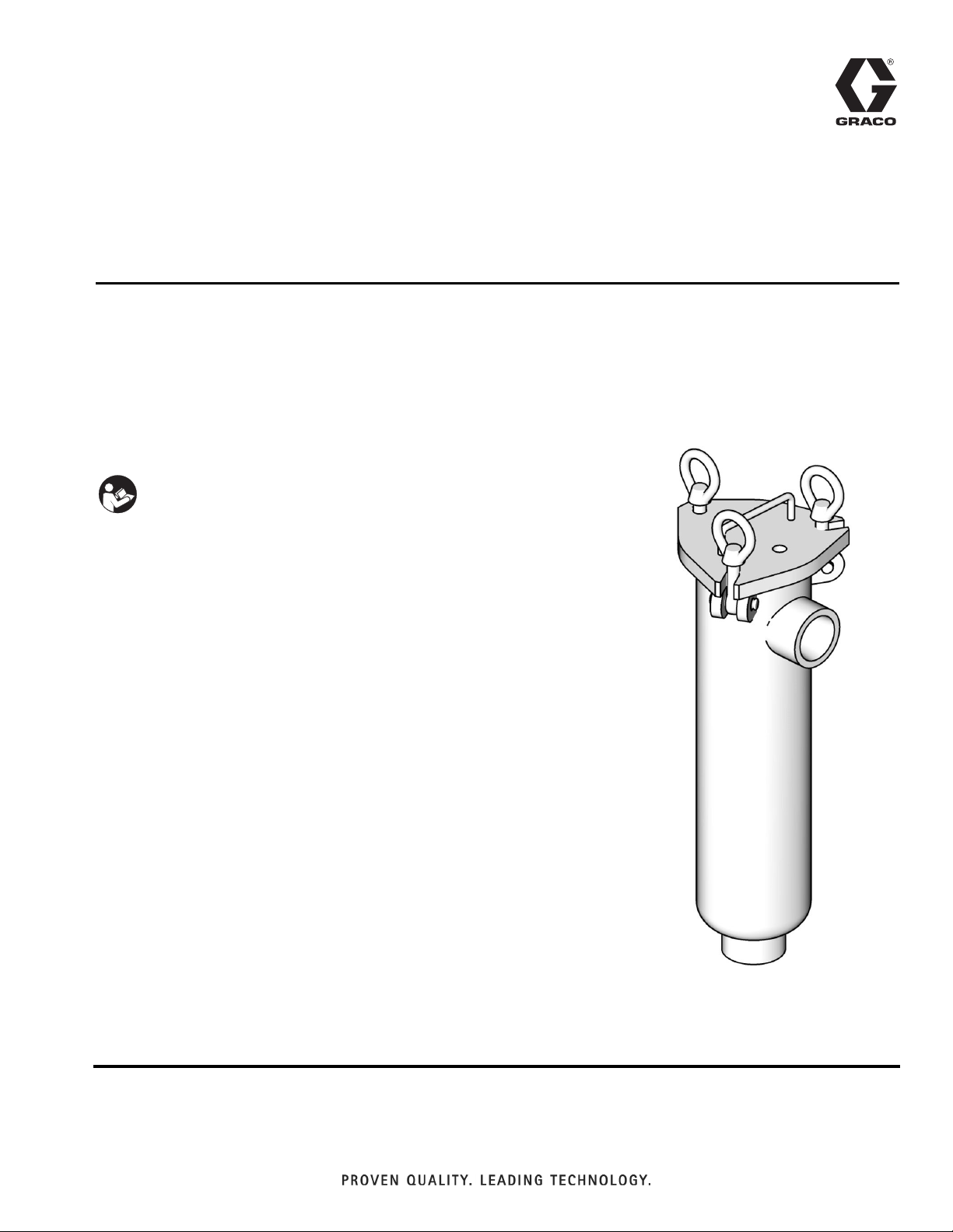
Instructions - Parts List
Low Pressure
311775E
Fluid Filters
For filtering large volumes of industrial paints and other industrial fluids. For professional
use only.
See page 3 for model numbers.
500 psi (3.5 MPa, 35 bar) Maximum Working Pressure.
Important Safety Instructions
Read all warnings and instructions in this manual.
Save these instructions.
EN
ti10097a
Page 2
Warnings
Warnings
The following warnings are for the setup, use, grounding, maintenance, and repair of this equipment. The exclamation point symbol alerts you to a general warning and the hazard symbols refer to procedure-specific risks. When
these symbols appear in the body of this manual, refer back to these Warnings. Product-specific hazard symbols and
warnings not covered in this section may appear throughout the body of this manual where applicable.
WARNING
EQUIPMENT MISUSE HAZARD
Misuse can cause death or serious injury.
• Do not operate the unit when fatigued or under the influence of drugs or alcohol.
• Do not exceed the maximum working pressure or temperature rating of the lowest rated system
component. See Technical Data in all equipment manuals.
• Use fluids and solvents that are compatible with equipment wetted parts. See Technical Data in all
equipment manuals. Read fluid and solvent manufacturer’s warnings. For complete information
about your material, request MSDS forms from distributor or retailer.
• Check equipment daily. Repair or replace worn or damaged parts immediately with genuine
manufacturer’s replacement parts only.
• Do not alter or modify equipment.
• Use equipment only for its intended purpose. Call your distributor for information.
• Route hoses and cables away from traffic areas, sharp edges, moving parts, and hot surfaces.
• Do not kink or over bend hoses or use hoses to pull equipment.
• Keep children and animals away from work area.
• Comply with all applicable safety regulations.
PRESSURIZED EQUIPMENT HAZARD
Fluid from the gun/dispense valve, leaks, or ruptured components can splash in the eyes or on skin
and cause serious injury.
•Follow Pressure Relief Procedure in this manual, when you stop spraying and before cleaning,
checking, or servicing equipment.
• Tighten all fluid connections before operating the equipment.
• Check hoses, tubes, and couplings daily. Replace worn or damaged parts immediately.
2 311775E
Page 3
Models
Part Model
Filter
Area
Inlet/Outlet
Fittings
Models
Maximum
Delivery
gpm (lpm) Material
915515
915516*
915517
915518*
* Waterborne compatible
6 0.5 sq ft 1-1/4 npt (f) 15 (57) Carbon steel
6 0.5 sq ft 1-1/4 npt (f) 15 (57) Stainless steel
12 1.0 sq ft 1-1/2 npt (f) 30 (114) Carbon steel
12 1.0 sq ft 1-1/2 npt (f) 30 (114) Stainless steel
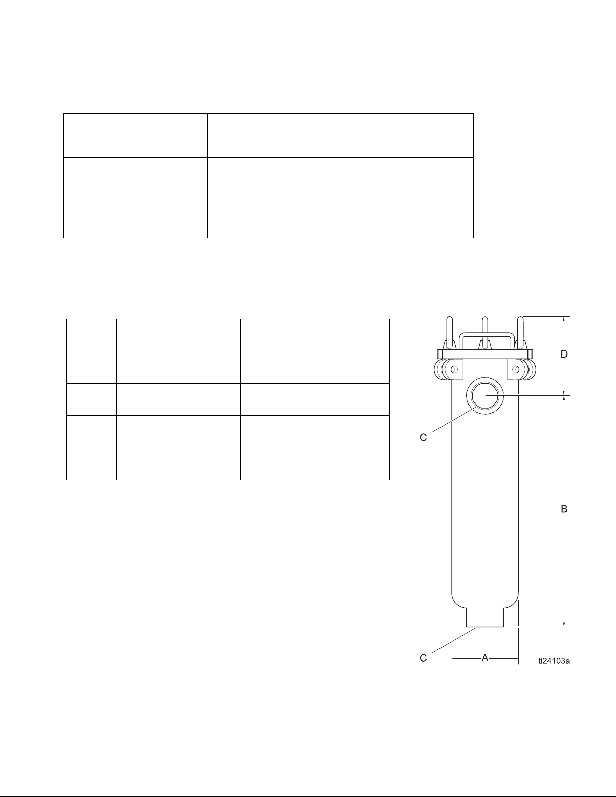
Dimensions
Width
Part No.
915515
915516
915517
915518
(A)
4.5 in. 9.5 in.
114.3 mm 241.3 mm (152.4 mm)
4.5 in. 9.5 in.
114.3 mm 241.3 mm (152.4 mm)
4.5 in. 15.5 in.
114.3 mm 393.7 mm (152.4 mm)
4.5 in. 15.5 in.
114.3 mm 393.7 mm (152.4 mm)
Length
(B)
Threads
(C)
1-1/4 NPT
1-1/4 NPT
1-1/2 NPT
1-1/2 NPT
Length
(D)
(6.0 in.)
(6.0 in.)
(6.0 in.)
(6.0 in.)
311775E 3
Page 4

Installation
Installation
NOTE: Reference numbers and letters in parentheses
in the text refer to the callouts in the parts drawing. (See
page 5.)
1. Connect the inlet line to the inlet (A) on the side of
the filter.
2. Connect the outlet line to the outlet (B) on the bottom of the filter.
NOTE: The 1/4 npt port in the cover of the filter can
remain plugged or be used for pressure gauges or special fittings.
3. Some installations require electrical grounding of all
equipment. Follow your local electrical code.
4. Remove cover by loosening the cover eye-nuts (3).
Loosen the eye-nuts in the slotted corners so the
bolts swing down. Loosen the third eye-nut so the
top cover can swing open.
5. Put basket (2) into filter housing. Make sure the basket flange is seated firmly on top of the basket collar.
6. Put bag into the bag basket. Be sure the filter bag
ring is seated firmly on top of the basket flange. For
best results, be sure the filter bag extends to the
bottom of the basket.
Operation
Prior to turning on the flow to the inlet, check the
following:
1. Be sure a basket and filter bag (if applicable) are in
place. Clean or replace as necessary.
2. Be sure the filter cover is securely fastened to housing.
Slowly open the inlet line to approximately 25% of normal operational flow. When the filter is pressurized and
vented, slowly open outlet line valve until completely
open. Open inlet line to reach desired flow rate.
NOTICE
Inlet pressure must not exceed outlet pressure by
more than 15 psi (0.1 MPa, 1 bar). Operating the filter
with a high differential may cause filter bags to rupture,
causing damage to filter system and downstream
equipment.
To prevent excessive drop through the filter, regularly
inspect the basket and filter bag. Monitor the differential
pressure through the filter to determine whether the basket or filter bag needs to be cleaned or replaced.
7. Make sure that the cover gasket groove is clean and
free of debris. Put in cover seal gasket (1).
NOTE: If the cover has ever been tightened down, the
cover seal gasket must be replaced.
8. Close cover and alternately tighten the three clamp
assemblies (by small increments) to a recommended torque of 30-45 ft-lb (40-60 N•m).
4 311775E
Page 5

Service
PRESSURIZED EQUIPMENT HAZARD
Before removing, cleaning, or servicing the filter,
close the inlet and outlet ball valves and open the
fluid drain valve to relieve pressure.
1. Relieve all fluid pressure from the system. See the
Warning above and your pump/sprayer manual.
NOTE: In some applications, closing outlet valve is not
required.
2. Drain housing sufficiently to access filter basket (2).
Service
1
2
3. Remove cover by loosening the cover eye-nuts (3).
Loosen the eye-nuts in the slotted corners so the
bolts swing down. Loosen the third eye-nut so the
top cover can swing open.
4. Remove filter basket (2) and clean thoroughly.
5. Remove the filter bag (if applicable, not shown) and
throw away. (Cleaning and reusing the filter bag is
not recommended.)
6. Thoroughly clean the inlet (A) to avoid interference
with cover seal or fluid flow.
7. Remove basket seal (if applicable) and inspect.
Replace if necessary.
8. Install clean filter basket and filter bag (if applicable). Put basket (2) into filter housing. Make sure the
basket flange is seated firmly on top of the basket
collar. Put bag into the bag basket. Be sure the filter
bag ring is seated firmly on top of the basket flange.
For best results, be sure the filter bag extends to the
bottom of the basket.
9. Make sure that the cover gasket groove is clean and
free of debris. Replace cover seal gasket (1).
3
A
B
ti10098a
NOTE: If the cover has ever been tightened down, the
cover seal gasket must be replaced.
10. Close cover and alternately tighten the three clamp
assemblies (by small increments) to a recommended torque of 30-45 ft-lb (40-60 N•m).
311775E 5
Page 6

Replacement Parts
Replacement Parts Replacement Filter Bags
Part Number
Ref.
1 521691 521691 Gasket, PTFE encapsu-
2 521268 521276 Bag filter basket, perfo-
521273 521280 Strainer basket, perfo-
3 521306 521306 Eye-bolt and nut
DescriptionModel 6 Model 12
lated fluoroelastomer
rated stainless steel,
standard with complete
assemblies
rated stainless steel with
100 mesh liner
Part Number
Model 6
(15 gpm)
521312 --
521316 --
521317 --
521183 --
521184 --
521186 521177
521187 521178
-- 521179
-- 521180
-- 521342
-- 521344
521335 --
521336 --
521337 --
521212 521240
521213 --
521215 --
521216 521244
521217 521245
521218 521246
521226 521254
521227 521255
521228 521256
521229 521257
521230 521258
521231 521259
521232 521260
521233 521261
521234 521262
521235 521263
521236 521264
Model 12
(30 gpm)
Material
Glazed polyester felt
without cover
Glazed polyester felt,
spun bonded nylon
cover
Glazed polyester felt,
nylon multi-filament
mesh cover
Glazed polyester felt,
nylon mono-filament
mesh cover
Nylon monofilament
mesh
Micron
size.
10
75
100
5
10
25
50
75
100
10
25
50
75
100
5
10
25
50
75
100
5
10
25
50
75
100
125
150
200
250
300
6 311775E
Page 7

Accessories
Pressure Gauge
2-1/2 in dial bourdon tube pressure gauge; range 0-200
psi (0-1.4 MPa, 1-14 bar); with pulsation dampener and
diaphragm seal.
Part Number
(Models 6 and 12) Description
Accessories
206171 carbon steel, 1/4 npt(f), bottom
208855 stainless steel, 1/4 npt(m), bot-
inlet
tom inlet
Ball Valve
For drain or air blowdown; 500 psi (3.5 MPa, 35 bar)
Part Number
(Models 6 and 12) Description
208390 carbon steel, 1/4 x 1/4 npt
208393 carbon steel, 3/8 x 3/8 npt
237534 stainless steel, 3/8 x 3/8 npt
NOTE: To order complete fluid filter assembly, see
Models on page 3.
(mbe)
(mbe)
(m x f)
311775E 7
Page 8

Graco Standard Warranty
Graco warrants all equipment referenced in this document which is manufactured by Graco and bearing its name to be free from defects in
material and workmanship on the date of sale to the original purchaser for use. With the exception of any special, extended, or limited warranty
published by Graco, Graco will, for a period of twelve months from the date of sale, repair or replace any part of the equipment determined by
Graco to be defective. This warranty applies only when the equipment is installed, operated and maintained in accordance with Graco’s written
recommendations.
This warranty does not cover, and Graco shall not be liable for general wear and tear, or any malfunction, damage or wear caused by faulty
installation, misapplication, abrasion, corrosion, inadequate or improper maintenance, negligence, accident, tampering, or substitution of
non-Graco component parts. Nor shall Graco be liable for malfunction, damage or wear caused by the incompatibility of Graco equipment with
structures, accessories, equipment or materials not supplied by Graco, or the improper design, manufacture, installation, operation or
maintenance of structures, accessories, equipment or materials not supplied by Graco.
This warranty is conditioned upon the prepaid return of the equipment claimed to be defective to an authorized Graco distributor for verification of
the claimed defect. If the claimed defect is verified, Graco will repair or replace free of charge any defective parts. The equipment will be returned
to the original purchaser transportation prepaid. If inspection of the equipment does not disclose any defect in material or workmanship, repairs
will be made at a reasonable charge, which charges may include the costs of parts, labor, and transportation.
THIS WARRANTY IS EXCLUSIVE, AND IS IN LIEU OF ANY OTHER WARRANTIES, EXPRESS OR IMPLIED, INCLUDING BUT NOT
LIMITED TO WARRANTY OF MERCHANTABILITY OR WARRANTY OF FITNESS FOR A PARTICULAR PURPOSE.
Graco’s sole obligation and buyer’s sole remedy for any breach of warranty shall be as set forth above. The buyer agrees that no other remedy
(including, but not limited to, incidental or consequential damages for lost profits, lost sales, injury to person or property, or any other incidental or
consequential loss) shall be available. Any action for breach of warranty must be brought within two (2) years of the date of sale.
GRACO MAKES NO WARRANTY, AND DISCLAIMS ALL IMPLIED WARRANTIES OF MERCHANTABILITY AND FITNESS FOR A
PARTICULAR PURPOSE, IN CONNECTION WITH ACCESSORIES, EQUIPMENT, MATERIALS OR COMPONENTS SOLD BUT NOT
MANUFACTURED BY GRACO. These items sold, but not manufactured by Graco (such as electric motors, switches, hose, etc.), are subject to
the warranty, if any, of their manufacturer. Graco will provide purchaser with reasonable assistance in making any claim for breach of these
warranties.
In no event will Graco be liable for indirect, incidental, special or consequential damages resulting from Graco supplying equipment hereunder, or
the furnishing, performance, or use of any products or other goods sold hereto, whether due to a breach of contract, breach of warranty, the
negligence of Graco, or otherwise.
FOR GRACO CANADA CUSTOMERS
The Parties acknowledge that they have required that the present document, as well as all documents, notices and legal proceedings entered into,
given or instituted pursuant hereto or relating directly or indirectly hereto, be drawn up in English. Les parties reconnaissent avoir convenu que la
rédaction du présente document sera en Anglais, ainsi que tous documents, avis et procédures judiciaires exécutés, donnés ou intentés, à la suite
de ou en rapport, directement ou indirectement, avec les procédures concernées.
Graco Information
For the latest information about Graco products, visit www.graco.com.
For patent information, see www.graco.com/patents.
TO PLACE AN ORDER,
Phone: 612-623-6921 or Toll Free: 1-800-328-0211 Fax: 612-378-3505
All written and visual data contained in this document reflects the latest product information available at the time of publication.
GRACO INC. AND SUBSIDIARIES • P.O. BOX 1441 • MINNEAPOLIS MN 55440-1441 • USA
Copyright 2007, Graco Inc. All Graco manufacturing locations are registered to ISO 9001.
contact your Graco distributor or call to identify the nearest distributor.
Graco reserves the right to make changes at any time without notice.
Original instructions.
International Offices: Belgium, China, Japan, Korea
This manual contains English. MM 311775
Graco Headquarters: Minneapolis
www.graco.com
Revision E, June 2014
 Loading...