

Page 1
Operation, Parts, Service, Repair
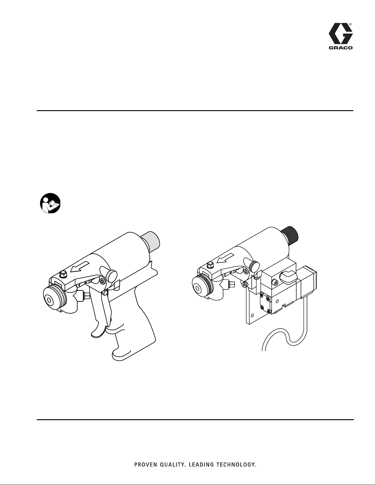
GX-8P Spray Gun
For use with non-flammable polyurethane foams, two-component coating systems
(polyureas), and some two-component epoxy systems. For professional use only.
Not for use in explosive atmospheres.
3500 psi (24 MPa, 240 bar) Maximum Working Pressure
125 psi (90 KPa, 9 bar) Maximum Air Working Pressure
Important Safety Instructions
Read all warnings and instructions
in this manual. Save these instructions.
311338J
EN
GX-8 Model 297898
GX-8P Auto Model 297860
Page 2
Models
Contents
Models . . . . . . . . . . . . . . . . . . . . . . . . . . . . . . . . . . . 2
Warnings . . . . . . . . . . . . . . . . . . . . . . . . . . . . . . . . . 3
Important Two-Component Material Information . 5
Isocyanate Conditions . . . . . . . . . . . . . . . . . . . . 5
Material Self-ignition . . . . . . . . . . . . . . . . . . . . . . 5
Keep Components A and B(R) Separate . . . . . . 5
Moisture Sensitivity of Isocyanates . . . . . . . . . . . 5
Foam Resins with 245 fa Blowing Agents . . . . . . 6
Overall View . . . . . . . . . . . . . . . . . . . . . . . . . . . . . . . 8
Centerline Components . . . . . . . . . . . . . . . . . . . 8
Mixing Module . . . . . . . . . . . . . . . . . . . . . . . . . . . 9
Operation Basics . . . . . . . . . . . . . . . . . . . . . . . . . . 10
Grounding . . . . . . . . . . . . . . . . . . . . . . . . . . . . . 10
Safety Position . . . . . . . . . . . . . . . . . . . . . . . . . 10
Air Hose Connection . . . . . . . . . . . . . . . . . . . . . 10
Coupling Block . . . . . . . . . . . . . . . . . . . . . . . . . 11
Air Inlet Configuration . . . . . . . . . . . . . . . . . . . . 12
Mixing Module and PCD Installation . . . . . . . . . 13
Valving Rod Adjustment . . . . . . . . . . . . . . . . . . 14
Initial Set Up . . . . . . . . . . . . . . . . . . . . . . . . . . . 15
Daily Start-up . . . . . . . . . . . . . . . . . . . . . . . . . . 16
Daily Shutdown . . . . . . . . . . . . . . . . . . . . . . . . . 16
Pressure Relief Procedure . . . . . . . . . . . . . . . . . . 17
Maintenance . . . . . . . . . . . . . . . . . . . . . . . . . . . . . . 18
Gun Service Kits . . . . . . . . . . . . . . . . . . . . . . . . 18
Clean Spray Gun Procedure . . . . . . . . . . . . . . . 18
Flush Gun . . . . . . . . . . . . . . . . . . . . . . . . . . . . . 19
Repair . . . . . . . . . . . . . . . . . . . . . . . . . . . . . . . . . . . 20
Service Screen Screw . . . . . . . . . . . . . . . . . . . . 20
Remove Check Valve . . . . . . . . . . . . . . . . . . . . 20
Remove Centerline Components . . . . . . . . . . . 21
Install Centerline Components . . . . . . . . . . . . . 21
Replace End Cap and Air Piston Assembly . . . 22
Replace Trigger Valve O-Rings . . . . . . . . . . . . . 25
Clean Mixing Module . . . . . . . . . . . . . . . . . . . . . 26
Troubleshooting . . . . . . . . . . . . . . . . . . . . . . . . . . . 27
Parts . . . . . . . . . . . . . . . . . . . . . . . . . . . . . . . . . . . . 28
GX-8 Gun Final Assembly (297898) . . . . . . . . . 28
GX-8 Handle Assembly (297702) . . . . . . . . . . . 30
GX-8P Spray Gun Final Assembly (297860) . . . 32
GX-8P Auto Cylinder Assembly (297861) . . . . . 34
Auto GX-8P Optional Parts . . . . . . . . . . . . . . . . 36
Coupling Block Assembly (295383) . . . . . . . . . 37
Coupling Block (297902) . . . . . . . . . . . . . . . . . . 38
Coupling Block Assembly (24N996) . . . . . . . . . 39
Set-up Chart for GX-8P Modules . . . . . . . . . . . . . 40
GX-8P Model Specifications . . . . . . . . . . . . . . . 40
Tool Kits . . . . . . . . . . . . . . . . . . . . . . . . . . . . . . . 40
Technical Data . . . . . . . . . . . . . . . . . . . . . . . . . . . . 41
Graco Standard Warranty . . . . . . . . . . . . . . . . . . . 42
Graco Information . . . . . . . . . . . . . . . . . . . . . . . . . 42
Models
Includes:
Part No. Description
Mix Module Tip Manifold
297898 ★ Gun, GX-8
297860 Gun, GX-8, Auto
24P633 ★ Gun, GX-8, with manifold 24N996 297911 296980
295338 (013) 297192 (201)
★
2 311338J
Starter
Kit
Not Included
Flushing
Kit
Page 3
Warnings
Warnings
The following warnings are for the setup, use, grounding, maintenance, and repair of this equipment. The exclamation point symbol alerts you to a general warning and the hazard symbols refer
to procedure-specific risks. When these symbols appear in the body of this manual, refer back to
these Warnings. Product-specific hazard symbols and warnings not covered in this section may
appear throughout the body of this manual where applicable.
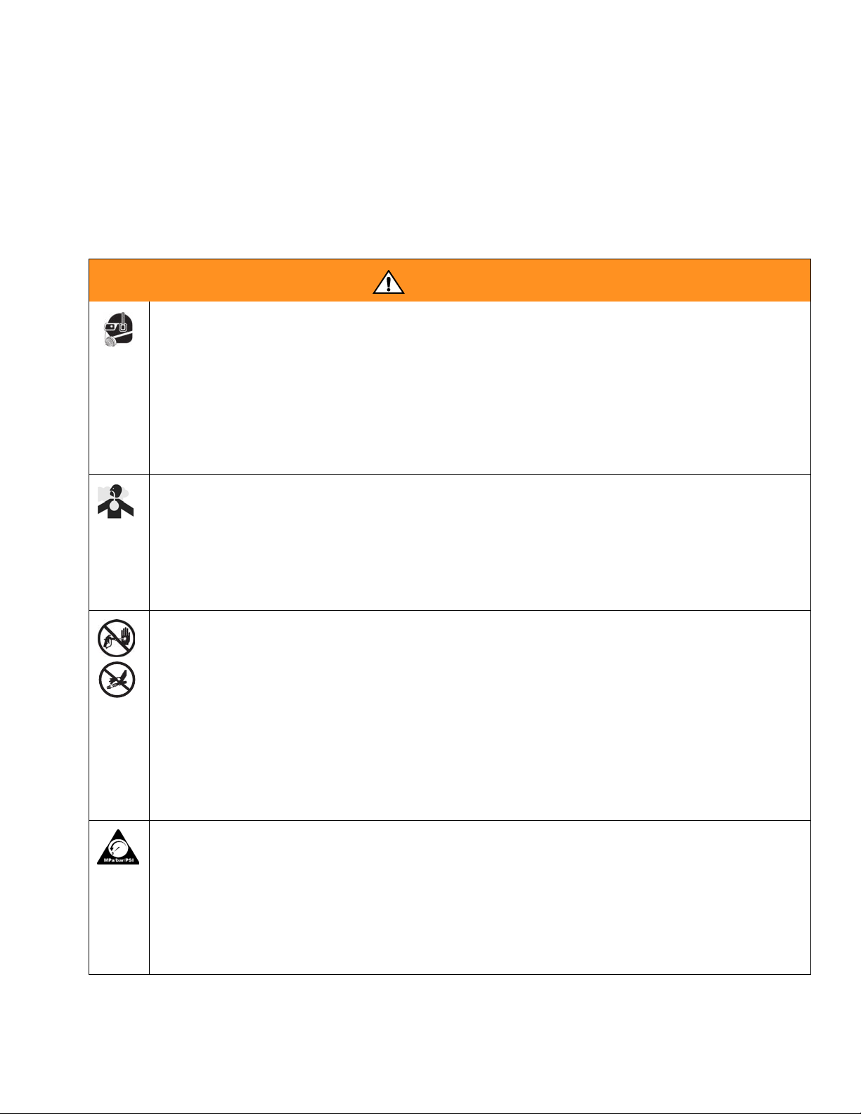
WARNING
PERSONAL PROTECTIVE EQUIPMENT
You must wear appropriate protective equipment when operating, servicing, or when in the
operating area of the equipment to help protect you from serious injury, including eye injury,
inhalation of toxic fumes, burns, and hearing loss. This equipment includes but is not limited to:
• Protective eyewear
• Clothing and respirator as recommended by the fluid and solvent manufacturer
•Gloves
• Hearing protection
TOXIC FLUID OR FUMES HAZARD
Toxic fluids or fumes can cause serious injury or death if splashed in the eyes or on skin,
inhaled, or swallowed.
• Read MSDS’s to know the specific hazards of the fluids you are using.
• Store hazardous fluid in approved containers, and dispose of it according to applicable
guidelines.
SKIN INJECTION HAZARD
High-pressure fluid from gun, hose leaks, or ruptured components will pierce skin. This may
look like just a cut, but it is a serious injury that can result in amputation. Get immediate
surgical treatment.
• Do not point gun at anyone or at any part of the body.
• Do not put your hand over the spray tip.
• Do not stop or deflect leaks with your hand, body, glove, or rag.
• Engage trigger lock when not spraying.
•Follow Pressure Relief Procedure in this manual, when you stop spraying and before
cleaning, checking, or servicing equipment.
PRESSURIZED EQUIPMENT HAZARD
Fluid from the gun/dispense valve, leaks, or ruptured components can splash in the eyes or on
skin and cause serious injury.
•Follow Pressure Relief Procedure in this manual, when you stop spraying and before
cleaning, checking, or servicing equipment.
• Tighten all fluid connections before operating the equipment.
• Check hoses, tubes, and couplings daily. Replace worn or damaged parts immediately.
311338J 3
Page 4
Warnings
WARNING
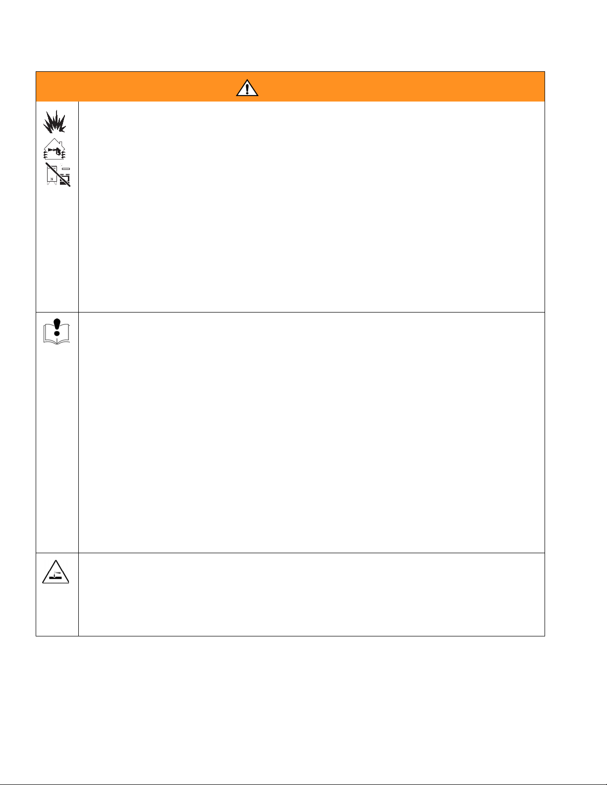
FIRE AND EXPLOSION HAZARD
Flammable fumes, such as solvent and paint fumes, in work area can ignite or explode. To
help prevent fire and explosion:
• Use equipment only in well ventilated area.
• Eliminate all ignition sources; such as pilot lights, cigarettes, portable electric lamps, and
plastic drop cloths (potential static arc).
• Keep work area free of debris, including solvent, rags and gasoline.
• Do not plug or unplug power cords, or turn power or light switches on or off when flammable
fumes are present.
• Ground all equipment in the work area. See Grounding instructions.
• Use only grounded hoses.
• Hold gun firmly to side of grounded pail when triggering into pail.
• If there is static sparking or you feel a shock, stop operation immediately. Do not use
equipment until you identify and correct the problem.
• Keep a working fire extinguisher in the work area.
EQUIPMENT MISUSE HAZARD
Misuse can cause death or serious injury.
• Do not operate the unit when fatigued or under the influence of drugs or alcohol.
• Do not exceed the maximum working pressure or temperature rating of the lowest rated
system component. See Technical Data in all equipment manuals.
• Use fluids and solvents that are compatible with equipment wetted parts. See Technical
Data in all equipment manuals. Read fluid and solvent manufacturer’s warnings. For complete information about your material, request MSDS forms from distributor or retailer.
• Check equipment daily. Repair or replace worn or damaged parts immediately with genuine
Graco/Gusmer replacement parts only.
• Do not alter or modify equipment.
• Use equipment only for its intended purpose. Call your Graco/Gusmer distributor for information.
• Route hoses and cables away from traffic areas, sharp edges, moving parts, and hot surfaces.
• Do not kink or over bend hoses or use hoses to pull equipment.
• Keep children and animals away from work area.
• Comply with all applicable safety regulations.
PRESSURIZED ALUMINUM PARTS HAZARD
Do not use 1,1,1-trichloroethane, methylene chloride, other halogenated hydrocarbon solvents
or fluids containing such solvents in pressurized aluminum equipment. Such use can cause
serious chemical reaction and equipment rupture, and result in death, serious injury, and property damage.
4 311338J
Page 5
Important Two-Component Material Information
Important Two-Component Material Information
Isocyanates (ISO) are catalysts used in two
component materials.
Isocyanate Conditions
Spraying or dispensing materials containing isocyanates creates potentially harmful mists,
vapors, and atomized particulates.
Read material manufacturer’s warnings and
material MSDS to know specific hazards and
precautions related to isocyanates.
Prevent inhalation of isocyanate mists, vapors,
and atomized particulates by providing sufficient
ventilation in the work area. If sufficient ventilation is not available, a supplied-air respirator is
required for everyone in the work area.
To prevent contact with isocyanates, appropriate
personal protective equipment, including chemically impermeable gloves, boots, aprons, and
goggles, is also required for everyone in the work
area.
Moisture Sensitivity of Isocyanates
Exposure to moisture (such as humidity) will
cause ISO to partially cure; forming small,
hard, abrasive crystals, which become suspended in the fluid. Eventually a film will form
on the surface and the ISO will begin to gel,
increasing in viscosity.
NOTICE
Partially cured ISO will reduce performance
and the life of all wetted parts.
• Always use a sealed container with a
desiccant dryer in the vent, or a nitrogen
atmosphere. Never store ISO in an open
container.
• Keep the ISO pump wet cup or reservoir
(if installed) filled with appropriate lubricant. The lubricant creates a barrier
between the ISO and the atmosphere.
Material Self-ignition
Some materials may become self-igniting if
applied too thick. Read material manufacturer’s
warnings and material MSDS.
Keep Components A and B(R) Separate
Cross-contamination can result in cured material
in fluid lines which could cause serious injury or
damage equipment. To prevent cross-contamination:
• Never interchange component A and component B(R) wetted parts.
• Never use solvent on one side if it has been
contaminated from the other side.
• Use only moisture-proof hoses compatible with ISO.
• Never use reclaimed solvents, which
may contain moisture. Always keep solvent containers closed when not in use.
• Always lubricate threaded parts with an
appropriate lubricant when reassembling.
NOTE: The amount of film formation and rate
of crystallization varies depending on the blend
of ISO, the humidity, and the temperature.
311338J 5
Page 6

Important Two-Component Material Information
Foam Resins with 245 fa Blowing Agents
Some foam blowing agents will froth at temperatures above 90°F (33°C) when not under
pressure, especially if agitated. To reduce
frothing, minimize preheating in a circulation
system.
6 311338J
Page 7

Important Two-Component Material Information
311338J 7
Page 8
Overall View
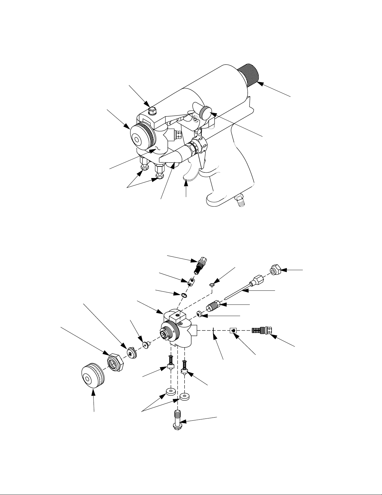
Overall View
Gun Block
Mounting Screw
Air Cap
Gun Block
FIG. 1: GX-8P Overall View
Manual
Valves
Coupling
Block
Safety Stop
125 PSI MAX
Air Cap Air
Adjustment
Valve
Trigger
Centerline Components
B-Screen Screw
Screen
Screen
Pattern Control
Disc (PCD)
PCD
Retainer
Gun Block
Air Cap
Retainer
Mixing
Module
B-Check
Valve
Coupling
Block Gasket
O-Ring
Screen
Retainer
A-Check
Valve
Coupling Block
Mounting Screw
Packing Nut
Rear Seal
Screen
Jam Nut
Valving Rod
Assembly
A-Screen
Screw
FIG. 2: GX-8P Centerline Components
8 311338J
Page 9
Mixing Module
Graco offers a variety of spray tip configurations to meet most applications that spray
fast-reaction chemical systems at low outputs.
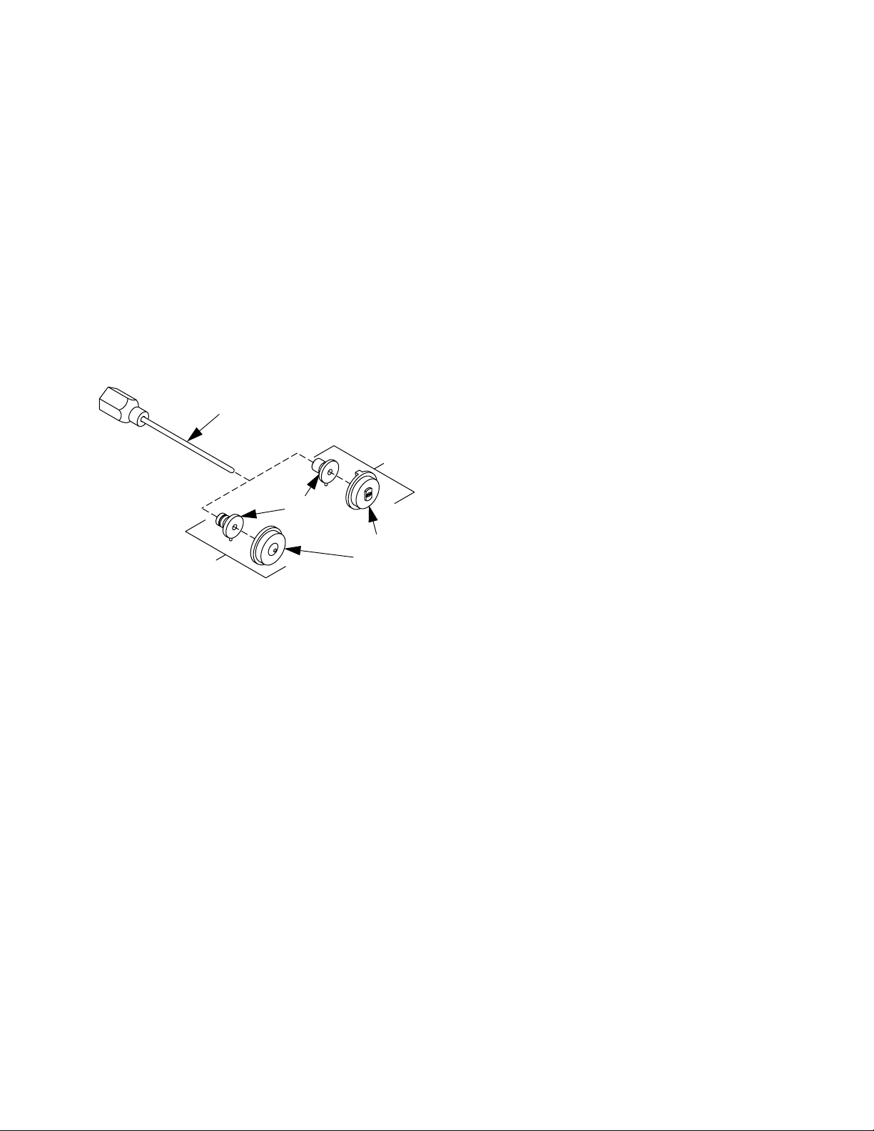
GX-8P spray tip components consist of a Pattern Control Disc (PCD) and a Mixing Module
(Figure 3). Tip components are available in a
range of sizes in both round and fan spray patterns. Please contact your authorized Graco
distributor to help you determine the best configurations for your specific application.
Valving Rod
Assembly
Fan Spray
Pattern
Overall View
Mixing
Module
Round
Spray Pattern
FIG. 3: Mixing Module & PCD
Pattern
Control
Disc (PCD)
311338J 9
Page 10
Operation Basics
1
Operation Basics
To prevent accidental gun operation, always
disconnect air supply before servicing gun or
anytime gun is not in use.
Grounding
Check your local electrical code and proportioner manual for detailed grounding instructions.
Ground spray gun through connection to
Graco-approved grounded fluid supply hose.
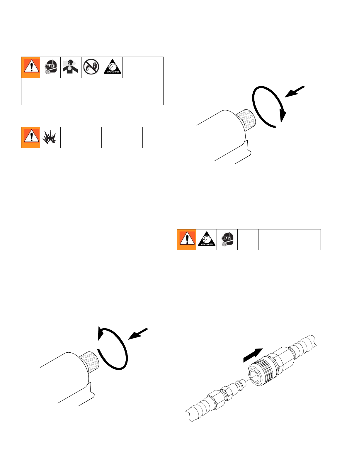
Disengage Safety Stop
To disengage safety stop, push in and turn
safety stop counterclockwise to place gun in
OPEN position.
Disengage the
Safety Stop
125 PSI MAX
FIG. 5: Safety Stop - Disengaged
Air Hose Connection
Safety Position
GX-8P guns have a two-position safety stop.
When engaged, it prevents accidental triggering of gun during servicing or down time. When
disengaged, it allows gun to dispense.
Engage Safety Stop
To engage safety stop, push in and turn safety
stop clockwise to place gun in CLOSED safety
position.
Engage the
Safety Stop
Connect Air Hoses
Pull back sleeve of female fitting, insert male
fitting and slide sleeve forward to secure connection.
Disconnect Air Hoses
Pull back sleeve of female fitting and pull out
male fitting.
Pull Sleeve
125 PSI MAX
FIG. 4: Safety Stop - Engaged
10 311338J
Page 11
Operation Basics
FIG. 6: Disconnect Air Hose
Coupling Block
Chemical hoses are joined to gun block by a
coupling block to ease installation and removal
of gun.
Manual Valves
Two manual valves located on coupling block
control flow of each chemical component to
gun.
Never open manual valve unless coupling
block is secured to gun or unless you point
gun into waste container.
Close Manual Valves
Use 5/16 in. nut driver to turn manual valve
fully clockwise.
To prevent accidental gun operation, always
set safety stop to CLOSED, close both manual valves, and disconnect air supply.
Installation and Removal
To prevent release of pressurized chemicals,
close both manual valves before coupling
block is removed.
NOTE: Triggering gun with manual valves
closed may cause crossover if any residual
chemical remains in gun ports.
Open Manual Valves
Use 5/16 in. nut driver to turn manual valve
counterclockwise approximately three full
turns.
Coupling
Block
Manual
Valves
Install Coupling Block
1. Replace nicked, damaged, or worn coupling block gaskets.
2. Ensure A-(isocyanate) and B-(resin) check
valves are inserted into their proper
recesses in gun block. Isocyanate valve is
notched for easy identification.
FIG. 7: Open Manual Valves
311338J 11
Page 12
Operation Basics
3. Fit coupling block into gun block and insert
coupling block mounting screw. Use 5/16
in. nut driver to tighten to gun block.
B-Check
Valve
A-Check
Valve
Coupling Block
Gaskets
Coupling Screw
Mounting Screw
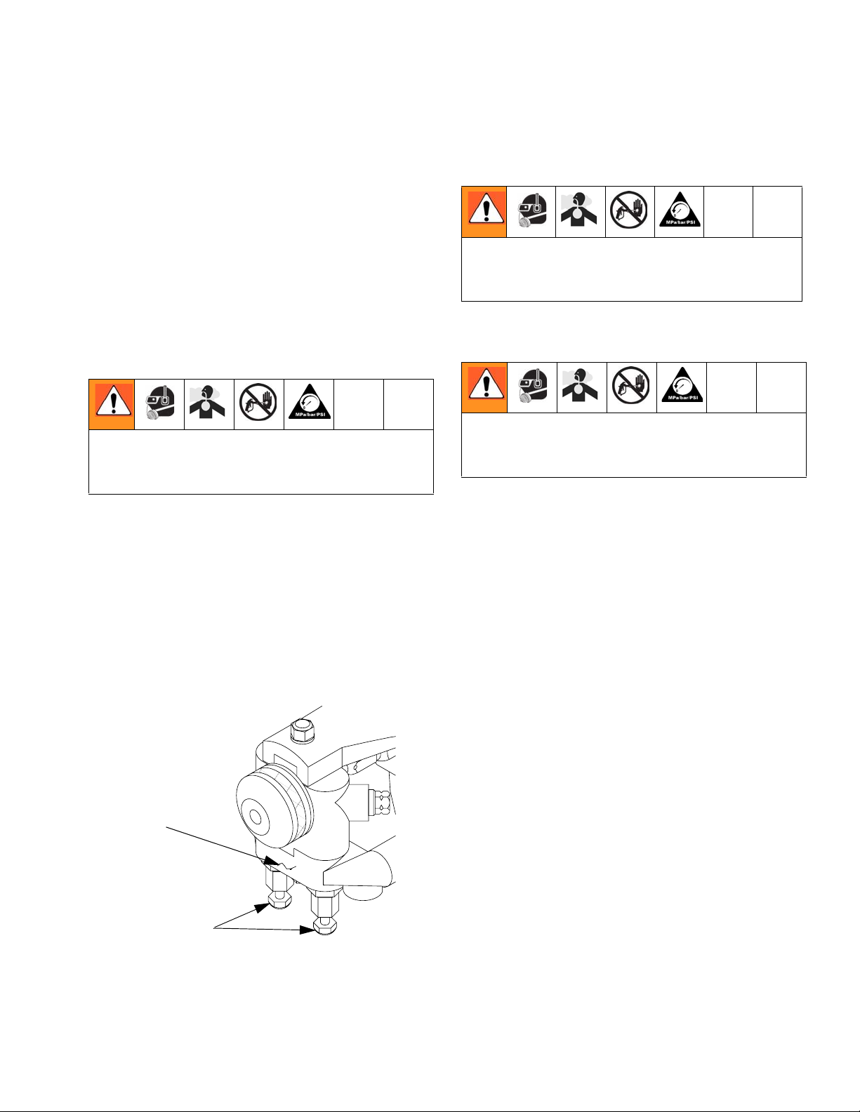
125 PSI MAX
Air Inlet Configuration
There are two configurations for the air inlet. In
the standard configuration, the air inlet is at
base of handle. In the alternate configuration,
the air inlet is at rear of gun.
Pipe Plug
125 PSI MAX
Pipe
Nipple
Optional
Pipe Plug
FIG. 8: Install Coupling Block
Remove Coupling Block
1. CLOSE safety stop.
2. Disconnect air hose.
3. Close both manual valves.
4. Remove coupling block mounting screw.
5. Separate coupling block from gun.
6. Wipe mating surfaces of gun block and
coupling block to remove residual chemicals.
7. Cover exposed openings with grease.
NOTE: To avoid accidental gun operation,
ensure coupling block manual valves are
closed before attempting to service gun, or any
time gun is not in use.
FIG. 9: Air Inlet Configuration
To change to alternate configuration:
1. Use 6 in. adjustable wrench to remove 4 in.
pipe nipple from base of gun.
2. Use 3/16 in. hex key to remove 1/8 in. pipe
plug from rear of gun.
3. Use 3/16 in. hex key to install 1/8 in. pipe
plug in location previously occupied by 4 in.
pipe nipple.
4. Use 6 in. adjustable wrench to install pipe
nipple in location previously occupied by
1/8 in. pipe plug.
12 311338J
Page 13

Mixing Module and PCD Installation
1. Loosen air cap by hand and remove.
2. Install mixing module:
a. Disconnect gun from coupling block.
b. Connect air supply to gun.
c. Set safety stop to OPEN.
d. Hold down trigger and place module
over tip of valving rod.
e. Align keying pin with slot in gun block
and keep gun trigger held down.
Operation Basics
3. Install PCD:
a. Hold down gun trigger and thread PCD
retainer in place by hand.
b. Use 10 in. adjustable wrench to care-
fully tighten PCD retainer until snug
enough to ensure no leak will occur.
c. Release gun trigger.
4. Install air cap and tighten by hand.
5. Adjust valving rod (see Valving Rod
Adjustment, page 14).
311338J 13
Page 14

Operation Basics
Valving Rod Adjustment
Valving rod should not require adjustment if it
was shipped from factory with mixing module
and PCD installed. Valving rod should only require adjustment when:
• Piston/rod assembly/ring is changed
• Valving rod is changed
• PCD is installed or changed
• Mixing module is installed or changed
To adjust valving rod:
1. Perform Clean Spray Gun Procedure,(see
page 18.
2. Connect air supply to gun.
3. Use 5/16 in. open-end wrench to loosen
packing nut 3 or 4 turns. This relieves pressure between seals and makes adjustment
easier.
Valving Rod
Assembly
4. Use 3/8 in. wrench on hex-shaped valving
rod shank and 1/2 in. wrench on jam nut to
loosen and back it away from valving rod by
3 or 4 full turns. Then move valving rod
toward gun cylinder. Turn valving rod shank
2 or 3 full turns clockwise.
5. Slowly turn valving rod counterclockwise to
move it toward PCD until resistance is felt.
Valving rod tip should touch inside spherical surface of PCD.
6. Carefully maintain 3/8 in. wrench in position
and tighten jam nut up against valving rod
shank to lock adjustment into place.
7. Retighten packing nut.
8. Check rear safety stop by attempting to disengage it. If knob will not turn, valving rod
is adjusted too far forward. Repeat steps 3 -
7. Make sure not to adjust valving rod past
the point resistance is felt. If safety stop disengages, proceed to step 9.
9. Trigger gun with safety stop disengaged to
confirm rear seal adjustment. Make sure
rod moves freely. If not, loosen packing nut
slightly until it does. Start to spray and
check for chemical seepage from packing
nut and retighten if necessary.
NOTE: If valving rod required adjustment as
part of initial mixing module and PCD installation on a new spray gun, proceed to Initial Set
Up, page 15.
Packing
Nut
FIG. 10: Valving Rod Adjustments
14 311338J
Jam Nut
Page 15

Operation Basics
Initial Set Up
1. Remove coupling block from gun.
2. Use two 6 in. adjustable wrenches to install
female quick disconnect fitting onto air supply hose bundled with chemical supply
hoses.
3. Use two 6 in. adjustable wrenches to connect A-isocyanate hose (red-taped) to
notched fitting on coupling block. Connect
B-resin hose (blue-taped) to fitting without
notches on coupling block.
4. Close both manual valves.
5. Pressurize A and B chemical hoses and
check for leaks (see Proportioner manual
as needed).
6. Bleed air from chemical hoses:
a. Hold coupling block with exit ports
pointed into waste container.
b. Use 5/16 in. nut driver to open each
manual valve; this allows any trapped
air to escape. Bleed each side for a
short time until chemicals leaving hoses
are free of air.
c. Close both manual valves.
7. Use cloth soaked in gun cleaner to clean
coupling block and mating surfaces.
NOTICE
Do not apply grease to mating surfaces of
coupling block to avoid accumulation of dirt
and other contaminants.
8. CLOSE safety stop.
9. Install coupling block to gun.
10.Proceed with daily start-up and shutdown
procedures as required.
311338J 15
Page 16

Operation Basics
Daily Start-up
Ensure gun is attached to coupling block and
air hose. Ensure proportioning unit is at
desired temperature and pressure. Properly
ground equipment to avoid static sparking
that may result in fire or explosion.
1. Connect air supply to gun.
2. Adjust air cap adjustment valve. Turn knob
counterclockwise to open valve and clockwise to close valve.
3. Open both manual valves.
4. OPEN safety stop.
5. Test spray on a disposable surface and
evaluate.
Daily Shutdown
NOTE: Follow daily shutdown procedure when
gun is out of service for any length of time, or
for mid- or end-of-day service. See Clean
Spray Gun Procedure, page 18.
1. CLOSE safety stop.
2. Close both manual valves.
3. Disconnect air supply from gun.
4. Shut down proportioning unit as required.
5. Clean as required (see Clean Spray Gun
Procedure, page 18).
NOTE: Disassembling gun for daily cleaning is
not recommended if gun has been operating
properly. However, if gun is removed from coupling block, it must be flushed and cleaned
thoroughly.
16 311338J
Page 17

Pressure Relief Procedure
Pressure Relief
Procedure
Relieve pressure before cleaning or repairing
gun.
1. Close both manual valves.
4. Release gun trigger, CLOSE safety stop,
and close manual valves.
If fluid in hose and proportioner is still under
pressure, follow Pressure Relief Procedure in
proportioner manual
To relieve pressure in hose after gun is
removed, place fluid manifold over containers,
facing away from you. Very carefully open
fluid valves (FIG. 13). Under high pressure,
fluid will spray sideways from fluid ports.
Manual Valves
FIG. 11: Close Manual Valves
2. OPEN safety stop.
3. Trigger gun onto cardboard or into waste
container to relieve pressure.
2
!
FIG. 13: Open Manual Valves
FIG. 12: Trigger Gun
311338J 17
Page 18

Maintenance
Maintenance
Gun Service Kits
Use either 1-Quart Gun Service Kit (296980)
or 3-Gallon Gun Service Kit (296981) to perform daily flushing of spray gun without disassembly.
FIG. 14: 1-Quart Gun Service Kit
For more information about 1-Quart Gun Service Kit, see Manual 311340.
FIG. 15: 3-Gallon Gun Service Kit
For more information about 3-Gallon Gun Service Kit, see Manual 311341.
Clean Spray Gun Procedure
To avoid static sparking that may result in fire
or explosion, ensure all equipment in cleaning
procedure is grounded. Do not clean on or
near foamed or coated surfaces or any other
flammable surfaces or objects.
Thoroughly flush gun block with gun cleaner
before removing valving rod or mixing components from gun block. Also allow chemicals in
spray gun to cool before cleaning.
This procedure makes use of the 1-Quart or
3-Gallon Gun Service Kit.
1. CLOSE safety stop.
2. Close both manual valves.
3. Remove gun from coupling block.
18 311338J
Page 19

Maintenance
4. Attach service block of gun service kit to
spray gun, and then tighten using 5/16 in.
nut driver.
5. Pressurize service kit container up to 100
psi. DO NOT EXCEED 100 psi (0.7 MPa, 7
bar).
6. Clean gun:
a. Set safety stop to OPEN.
b. Open either manual valve on service
block.
c. Trigger gun and gun service kit simulta-
neously with gun aimed into waste container.
d. Release both triggers and close manual
valves on service block.
Flush Gun
To avoid static sparking that may result in fire
or explosion, ensure all equipment in flushing
procedure is grounded. Do not flush on or
near foamed or coated surfaces.
1. CLOSE safety stop.
2. Close both manual valves.
3. Loosen B-Screen screw and then remove
by hand.
4. Use flush can to thoroughly flush screen
screw and screen screw cavity.
5. Loosen A-Screen screw and then remove
by hand.
e. Repeat procedure for other side of gun.
f. After initial cleaning, remove air cap,
PCD retainer, and PCD. Flush a second
time to ensure thorough cleaning.
7. CLOSE safety stop.
8. Disconnect air supply from gun.
9. Remove service block of gun service kit
from gun.
10.Clean screens, check valves and screen
screw (see Service Screen Screw, page
20.
NOTE: Inspect air cap, PCD, mixing module,
and gun block for build up of material and
clean as required.
6. Use flush can to thoroughly flush screen
screw and screen screw cavity.
7. Service gun, see Maintenance procedures, page 18.
Do not use metal cleaning devices to clean
plastic components.
311338J 19
Page 20

Repair
Repair
Shutdown proportioner and allow chemicals
to cool before servicing gun.
Service Screen Screw
To avoid static sparking that may result in fire
or explosion, ensure all equipment in flushing
procedure is grounded. Do not flush on or
near foamed or coated surfaces.
1. Flush gun see Clean Spray Gun Proce-
dure, page 18.
2. Unthread screen screw from gun block.
3. Remove screen screw retainer before
removing screen.
4. Remove screen from screen screw. Soak in
gun cleaner or replace if clogged or dirty.
5. Clean screen screw cavity. If any particles
are visible, clean with clean out drills and
flush with gun cleaner.
NOTE: Any material left in cavity on downstream side of screen will clog mixing module.
6. Inspect screen screw seal for damage.
Replace if necessary.
7. Reinstall screen screw in gun block. Ensure
it is tight.
8. Flush gun with mixing module removed.
Remove Check Valve
To avoid static sparking that may result in fire
or explosion, ensure all equipment in flushing
procedure is grounded. Do not flush on or
near foamed or coated surfaces.
Check valves are located in cavities of gun
block under each coupling block gasket. Check
valves are triangular pieces with a spring inserted in one end. The isocyanate valve is notched
for easy identification.
To remove check valve:
1. Clean gun (see Clean Spray Gun Proce-
dure, page 18).
2. Use check valve seal removal/cleaning tool
to remove gaskets from recesses in coupling block. Inspect gaskets for damage
and replace if necessary.
3. Remove check valves. If valve does not
come out easily, insert machined end of
removal/cleaning tool over valve and rotate
it while extracting valve.
4. Clean valves and springs with gun cleaner.
Inspect for damage and replace if necessary.
5. Inspect each check valve cavity. Use cleaning tool to remove any visible particles. Use
gun cleaner to flush thoroughly.
6. Insert each check valve into its cavity
spring end first. Ensure check valve is oriented correctly. Isocyanate valve is notched
for easy identification.
7. Install coupling block gaskets.
20 311338J
Page 21

Repair
Remove Centerline Components
Refer to page 8 for diagrams of centerline
components for all gun models.
1. Flush gun (see Clean Spray Gun Proce-
dure, page 18).
2. Remove air cap (loosen by hand).
3. Use 10 in. adjustable wrench to remove
PCD.
4. Connect air supply to gun.
5. Lift PCD off nose of gun block and remove.
NOTE: To remove PCD that is stuck, set safety
stop to OPEN, depress and release gun trigger
to unseat it. CLOSE safety stop.
11.Remove and clean check valves (see
Remove Check Valve, page 20).
12.Remove valving rod:
a. Use 3/8 in. wrench on hex-shaped valv-
ing rod shank and a 1/2 in. wrench on
jam nut to loosen it and back it away
from valving rod shank by 3 or 4 full
turns.
b. Unthread valving rod from piston shaft
and remove.
13.Clean all components thoroughly before
reassembly.
14.Inspect gun block to ensure proper operation of spray gun.
6. Remove mixing module retainer.
7. OPEN safety stop. Depress and release
gun trigger to unseat it. Remove mixing
module off end of valving rod. CLOSE
safety stop.
NOTICE
Do not use sharp objects or metal tools to
remove mixing module.
8. Disconnect air supply from gun.
9. Use 5/16 in. wrench to loosen packing nut
3 or 4 turns.
10.Remove gun block:
a. Use 5/16 in. nut driver to remove gun
block retaining screw.
Install Centerline Components
Before installation, ensure all gun components
are clean and dry. Lubricate all moving parts
and threads.
1. To install valving rod, thread jam nut as far
back on piston shaft as possible. Screw
shank end of valving rod onto threaded end
of piston rod.
2. Install rear seal and packing nut if removed.
Thread packing nut into gun block by hand,
but do not tighten.
3. To install gun block, carefully slide gun
block onto valving rod towards air cylinder.
Use 5/16 in. nut driver to install gun block
onto gun block mounting bracket.
4. Connect air supply to gun.
b. Slide gun block away from valving rod
and air cylinder. If dried chemical is built
up on gun block, remove dried chemicals to make removal easier.
311338J 21
5. OPEN safety stop.
Page 22

Repair
6. To install mixing module, hold down gun
trigger and slide module over end of valving
rod. Make sure to align keypin with slot in
gun block. Keep gun trigger depressed and
proceed to step 7.
7. To install PCD, hold gun trigger in and
place PCD over mixing module. If installing
a fan tip, position PCD according to which
spray direction is needed (vertical or horizontal). Keep gun trigger depressed and
proceed to step 8.
NOTE: Parts must align properly or chemical
flow from gun block ports will not enter mixing
module when gun is triggered.
8. Install PCD retainer:
a. With gun trigger depressed, thread
PCD retainer in place by hand.
Replace End Cap and Air Piston Assembly
End Cap/Safety
Stop Assembly
Retaining
Ring
Piston
Spring
FIG. 16: End Cap and Air Piston Assembly
Piston
End Cap
O-Ring
Cylinder
Cup Seal
Piston
O-Ring
#8 Socket Head
Cap Screw
b. Use 10 in. adjustable wrench to care-
fully tighten PCD retainer until it is snug
enough to ensure no leak will occur.
c. Release gun trigger.
NOTICE
To avoid damage to module and gun block,
do not overtighten mixing module retainer.
9. Install air cap and tighten by hand.
10.Adjust valving rod (see Valving Rod
Adjustment, page 14).
1. Clean gun (see Clean Spray Gun Proce-
dure on page 18).
2. Disconnect air supply from gun.
3. Use 5/16 in. wrench to loosen packing nut
3 or 4 turns (remove nut completely if rear
seal needs to be replaced).
4. Remove gun block:
a. Use 5/16 in. nut driver to remove gun
block mounting screw.
b. Carefully slide gun block away from
valving rod and air cylinder. If dried
chemical has built up on gun block,
remove dried chemical to make removal
easier.
c. Remove valving rod and jam nut (see
Remove Check Valve, page 20):
22 311338J
Page 23

Repair
d. Use 3/8 in. wrench on hex-shaped valv-
ing rod shank and 1/2 in. wrench on jam
nut.
e. Loosen jam nut and back it away from
valving rod shank by 3 or 4 full turns.
f. Unthread valving rod and jam nut from
piston shaft.
5. OPEN safety stop.
6. Use 9/64 in. ball point hex key to remove
socket head cap screw that holds air cylinder to handle (FIG. 16).
7. Use retaining ring 45° pliers to remove
retaining ring that holds end cap in place
inside air cylinder.
8. Remove end cap/safety stop assembly and
piston spring:
a. Pull safety stop and attached end cap
out of air cylinder.
b. Remove piston spring located inside
cylinder. Be sure to retain spring for
reinstallation.
a. Remove piston/rod assembly:
Use gun block mounting screw (screw
that holds gun block to bracket) to aid in
removal of piston.
b. Look into rear of air cylinder and thread
mounting screw into center hole of piston at least 4 full turns.
c. Use 6 in. pliers to grab mounting screw
and pull piston rod assembly out of air
cylinder.
d. Inspect ring and replace if damaged.
Apply light coat of Lubriplate grease
and install new ring.
10.Inspect air cylinder cup seal. If air escapes
around piston rod during operation, remove
and replace cup seal located in front of air
cylinder. Lubricate new cup seal with Lubriplate grease and install it. Make sure cup
faces toward rear of cylinder.
11.Insert piston and rod assembly into air cylinder. Be careful not to damage cup seal in
front face of air cylinder as rod passed
though. Remove gun block mounting screw
from piston.
NOTE: Force will be required to remove end
cap because ring is tightly compressed.
9. Inspect end cap ring. Replace if damaged.
Apply light coating of Lubriplate grease and
install new end cap ring.
NOTE: Skip steps 11-13 and go to step 14 if
only end cap ring and cup seal need to be
replaced.
311338J 23
Page 24

Repair
12.Disassemble safety stop mechanism:
a. Use 5/64 in. hex key to remove two set
screws from knob.
b. Slide knob off stop pin and retain stop
pin spring.
c. Pull shaft out of end cap (FIG. 17).
13.Remove cup seal from end cap and inspect
for damage. Remove if damaged. Apply
light coat of Lubriplate grease and install
new end cap ring.
Knob
Set Screws
End Cap
Cup Seal
O-ring
Spring
Stop Pin
d. Maintain pressure on end cap. Ensure
groove remains visible.
16.Use retaining ring 45° pliers to reinstall
retaining ring into groove.
Retaining ring must seat completely into
groove to secure end cap in place when air
cylinder is pressurized. Keep clear of cap
when air pressure is applied or gun is triggered after reassembly.
17.Use 9/64 in. ball-point hex key to install and
tighten socket head cap screw, which holds
air cylinder to handle.
18.Reinstall valving rod and jam nut:
a. Thread jam nut as far as it will go onto
threaded end of piston shaft.
b. Ensure hex end of nut faces rear.
FIG. 17: End Cap/Safety Stop Assembly
14.Reassemble safety stop mechanism:
a. Insert stop pin into end cap hole.
b. Slide spring and knob onto stop pin.
c. Use 5/64 in. hex key to reinstall two set
screws into knob. Ensure knob is
secure.
15.Reinstall end cap/safety assembly and piston spring:
a. Insert piston spring and align over
raised center of piston.
b. Line up raised center of end cap with
spring and insert end cap into air cylinder.
c. Thread valving rod as far onto threaded
portion of piston rod as possible.
19.Thread packing nut into gun block by hand
but do not tighten.
20.Install gun block:
a. Ensure ring is in place in top of gun
block.
b. Carefully slide gun block onto valving
rod toward air cylinder.
c. Use 5/16 in. nut driver to install gun
block onto gun block mounting bracket.
21.Adjust valving rod (see Valving Rod
Adjustment on page 14).
c. Press end cap until it moves past retain-
ing ring groove in cylinder.
24 311338J
Page 25

Repair
Replace Trigger Valve O-Rings
1. Clean gun (see Clean Spray Gun Procedure, page 18).
2. Perform Pressure Relief Procedure, page
17.
3. Disconnect air supply from gun.
Refer to Parts, page 28.
1/16 in. Pipe
Plug
Spring
Seat
Valve
Liner
O-rings
03)-!8
1/8 in.
Pipe Plug
c. Apply thin coat of Lubriplate grease to
new rings and reinstall.
NOTE: Follow steps 7-14 to replace rings on
valve liner. If rings do not need to be replaced,
proceed to step 15.
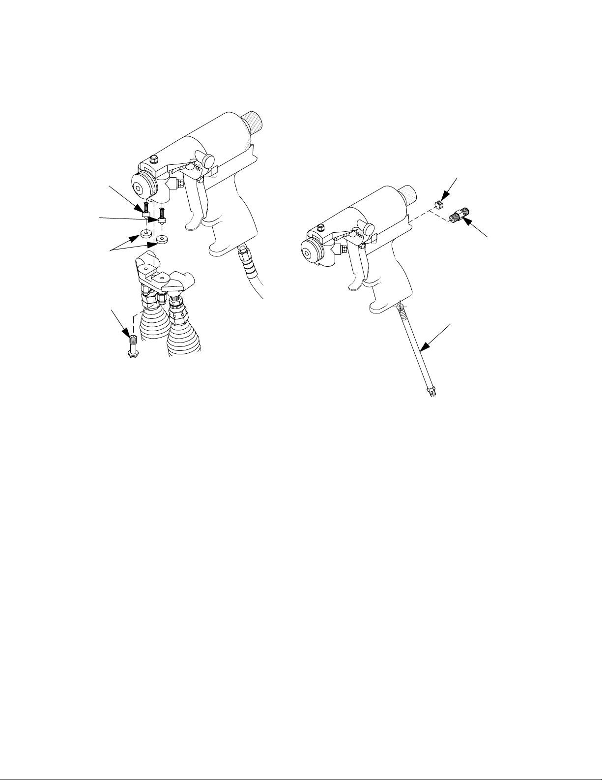
7. Use 3/16 in. hex key to remove 1/8 in. rear
internal plug. This plug seals another airflow path in gun handle.
NOTE: For guns configured with air inlet at
rear of gun handle, pipe nipple replaces pipe
plug. Remove pipe nipple.
8. Use 5/32 in. hex key to remove rear internal
pipe plug (under pipe plug).
9. Use pin punch and hammer to gently tap
spring seat until it and valve liner push out
opposite end of hole.
Valve
Spring
Valve
Spool
Valve Retainer Nut
FIG. 18: Replace Trigger Valve O-Ring
Trigger Lever
Optional 1/8 in.
Pipe Nipple
Trigger Mounting
Screw
4. Use 6 in. adjustable wrench and 6 in. pliers
to remove screw and locknut that hold trigger lever in place. Remove trigger lever.
5. Use 3/8 in. wrench to loosen and remove
valve retainer nut.
6. Remove valve spool and spring:
a. Grab end of spool and pull out. Spring
will come out with spool. Do not lose
spring--it belongs in hole at end of
spool.
10.Remove rings on liner. Apply thin coat of
Lubriplate grease to new rings and install.
11.Clean valve hole. Remove any dirt and
debris. Apply thin coat of Lubriplate grease
to inside of valve hole.
12.Slide spring seat into gun handle air valve
hole, tapered end first, until it bottoms out.
13.Push valve liner in as far as it will go. Install
valve retainer nut, it will align valve liner
and spool to their proper depth.
14.Use 5/32 in. hex key to screw 1/16 in. pipe
plug back into place. Apply think coat of
pipe thread sealant to threads prior to
insertion to help prevent air leaks.
15.Apply small amount of pipe thread sealant
to 1/8 in. plug threads. Screw pipe plug in
place.
b. Remove old rings.
16.Insert valve spool into valve liner with valve
spool spring still in place. Screw in valve
retainer nut; tighten until snug.
311338J 25
Page 26

Repair
17.Use screw and locknut to reinstall trigger
lever.
Clean Mixing Module
1. Flush gun (see Clean Spray Gun Procedure, page 18).
2. Connect air supply to gun. OPEN safety
stop.
3. Remove air cap by hand.
9. Inspect valving rod for damage and replace
as required. Use cloth soaked in gun
cleaner or steel wool to clean and remove
buildup of mixed material from rod.
NOTE: If valving rod is replaced, reset forward
stop.
10.Cleanmixing module.
NOTE: Ensure cleanout tool size matches
module size used.Insert cleanout tool into pin
vise.
d. Use cleanout tool to clean module
ports. Make sure not to insert tool too
far, it will damage inside bore of module.
Use cotton swab soaked in gun cleaner
to clean bore of module.
FIG. 19: Unthread Cap from PCD Body
4. Trigger gun and hold it to relieve pressure
on PCD retainer.
5. Turn PCD retainer counterclockwise and
remove.
6. Remove PCD from mixing module retainer.
NOTE: To remove PCD that is stuck, set safety
stop to OPEN, depress and release gun trigger
to unseat it. CLOSE safety stop.
7. Remove mixing module retainer.
8. OPEN safety stop. Depress and release
gun trigger to unseat it. Remove mixing
module from end of valving rod. CLOSE
safety stop.
FIG. 20: Clean Module Ports
26 311338J
Page 27

Troubleshooting
Follow Pressure Relief Procedure, page 17,
before checking or repairing gun.
Troubleshooting
NOTICE
To prevent cross-contamination of the equipment’s wetted parts, never interchange component A (isocyanate) and component B
Use the following table to check all possible
problems and causes before disassembling
gun. See Maintenance on page 18 for referenced procedures.
(resin) parts. The gun is shipped with the A
side on the left. The gun block and the screen
screw are marked.
Problem Cause Solution
Gun does not fully actuate Safety lock engaged Disengage piston safety lock
Air not vented on open/close ports Vent open air port when closing,
vent close air port when opening
Loss of air Check air source
Fluid does not pour when gun is
fully actuated
Gun actuates slowly Loss of air pressure Check air source
Gun delays, then actuates abruptly Cured material around the purge
Gun does not actuate Air supply to gun is shut off Open air supply
Pressure imbalance Plugged orifice ports Clean orifice ports
Fluid does not shut off when fluid
valves are closed
Leak between air cylinder and fluid
housing
Material leaking out weep ports in
fluid housing near air cylinder
Closed manual valves Open valves
Plugged orifice ports Clean orifice ports
Plugged check valves Clean check valves
Safety lock engaged Disengage piston safety lock
Damaged piston o-rings Replace air piston o-rings
Inspect purge rod, mix module,
rod
Foam build-up around front tip Clean off front tip.
Plugged check valves Clean check valves
Plugged fluid screens Clean screens
Damaged fluid valves Replace
Damaged o-ring Replace
Mix module and rear seal worn Inspect and replace mix module
and orifices. Replace if necessary
and rear seal, clean fluid housing
311338J 27
Page 28

Parts
Parts
GX-8 Gun Final Assembly (297898)
12
19
23
15
22
21
17
8
11
24
10
20
11
4
3
2
9
17
16
18
13
14
03)-!8
1, 25
6
5
28 311338J
Page 29

GX-8 Gun Final Assembly (297898)
Ref. Part Description Qty.
1 15B772 HOSE, air, 1/4 in. x 23 in.
(F x F)
2 296128 GASKET, block, gasket 2
3 295623 VALVE, check, A 1
4 295624 VALVE, check, B 1
5 295596 PLUG, coupler 1
6 208536 Coupler, line, air 1
8 106560 PACKING, O-ring 1
9 295433 SCREW, mounting, block,
coupling
10 297680 NUT, seal, rear 1
11 297681 RETAINER, screen 2
12 297682 SCREW, mounting, block,
gun
13 297683 NUT, jam 1
14 297702 HANDLE, assembly 1
15 297684 RETAINER, PCD 1
16 295341 ROD, valving 1
17 297193 SCREEN, gun block, 100
mesh
18 297686 SCREW, screen, iso 1
19 297687 SCREW, screen, res 1
20 295437 PACKING, seal, rear 1
21 295338 MODULE, fan 1
22 297192 TIP, fan 1
23 297705 CAP, air 1
24 297901 BLOCK, gun 1
25 100030 Fitting 1
Parts
1
1
1
2
311338J 29
Page 30

Parts
GX-8 Handle Assembly (297702)
80
97
104
102
103
101
72
98
106
85
91
96
100
89
82
75
106
81
79
94
105
92
88
93
77
86
99
84
95
76
76
74
03)-!8
83
90
87
73
30 311338J
Page 31

GX-8 Handle Assembly (297702) GX-8 Gun Kit (297832)
Ref. Part Description Qty.
72 295435 SEAL, u-cup 1
73 295709 SCREW, cap, socket head 2
74 295662 PLUG, pipe 1
75 295732 SCREW, cap, sh, 8-32 x 1/4
LG
76 103337 PACKING, ring 3
77 106555 PACKING, ring 4
79 C02032 NUT 1
80 296627 SEAL, u-cup 1
81 295692 TRIGGER, gun, spray 1
82 116624 SCREW, set, socket head 2
83 295693 PLUG, pipe 1
84 296971 SPRING 1
85 108103 PACKING, ring 1
86 168518 PACKING, ring 1
87 295665 FITTING, nipple, pipe 1
88 295671 SCREW, mounting, trigger 1
89 296538 RING, retaining 1
90 297689 HANDLE, gun 1
91 16T691 CYLINDER, air 1
92 295686 LINER, valve 1
93 295687 SPOOL, valve 1
94 295688 NUT, retainer, valve 1
95 295689 SEAT, spring 1
96 295436 SPRING 1
97 297691 PISTON, assembly 1
98 296529 CAP, end 1
99 297693 NEEDLE, adjust, air 1
100 296530 KNOB, gap 1
101 296526 PIN, stop 1
102 295416 SPRING, piston 1
103 297694 BRACKET, assembly 1
104 114054 PACKING, ring 1
105 C20004 SCREW, cap 2
106 295685 RING 4
1
202
Ref. Part Description Qty.
201 297898 GUN 1
202 295383 BLOCK, coupling 1
203★296980 KIT, service; includes
203a-203k
203a SPRAYER, solvent, flush 1
203b VALVE, service, air 1
203c SCREW, mounting, block,
coupling
203d VALVE, manual 2
203e NIPPLE, JIC 1
203f SCREW, block, coupling 1
203g BLOCK, service 1
203h FITTING; 3/8 in. x 7/16 in. 1
203k HOSE; 3/16 ID x 3 ft 1
204★297911 KIT, starter; includes
204a-204g
204a PIN, vise 1
204b MODULE, fan, 013 1
204c TIP, round, 020 1
204d MODULE, round, 020 1
204e TIP, round, 024 1
204f TIP, fan, 201 1
204g TIP, fan, 202 1
125 PSI MAX
Parts
201
1
1
1
★ Not shown.
311338J 31
Page 32

Parts
GX-8P Spray Gun Final Assembly (297860)
120
127
130
129
131
125
114
126
116
121
119
122
118
113
107
128
109
123
124
117
110
108
115
FIG. 21: GX-8P Spray Gun Final Assembly
111
112
32 311338J
Page 33

GX-8P Spray Gun Final Assembly (297860)
Ref. Part Description Qty.
107 15B772 HOSE, air, 1/4 X 23 in. (F X F) 1
108 296128 GASKET, block, gasket 2
109 295623 VALVE, check, A 1
110 295624 VALVE, check, B 1
111 295596 PLUG, coupler 1
112 208536 COUPLER, line, air 1
113 191872 FITTING, pipe, hex 1
114 106560 PACKING, o-ring 1
115 295433 SCREW, mounting, block,
coupling
116 297680 NUT, seal, rear 1
117 297681 RETAINER, screen 2
118 297682 SCREW, mounting, block, gun 1
119 297683 NUT, jam 1
120 297684 RETAINER, pod 1
121 295341 ROD, valving 1
122 297861 CYLINDER, GX-8P, auto 1
123 297193 SCREEN, gun block,
100 mesh
124 297686 SCREW, screen, iso 1
125 297687 SCREW, screen, res 1
126 295437 PACKING, seal, rear 1
127 297705 AIR, cap 1
128 112307 ELBOW, street 1
129 297901 BLOCK, gun 1
130 297192 TIP, fan 1
131 295338 MODULE, fan 1
1
2
Parts
311338J 33
Page 34

Parts
GX-8P Auto Cylinder Assembly (297861)
51
47
49
26
52
58
59
48
45
36
38
35
60
30
39
53
50
61
27
37
46
28
31
61
32
54
32
57
33
34
44
43
29
60
33
56
40
42
41
FIG. 22: GX-8P Auto Cylinder Assembly
34 311338J
Page 35

GX-8P Auto Cylinder (297861)
Ref. Part Description Qty.
26 295435 SEAL, u-cup 1
27 295709 SCREW, cap, socket head 4
28 295732 SCREW, cap, sh,
8-32 X 1/4 LG
29 104376 SCREW, cap, sch 2
30 297743 TIE, cable, #6 1
31 C20988 PACKING, o-ring 2
32 103337 PACKING, o-ring 4
33 297253 WASHER, helical, .188 in.
diameter
34 104705 SCREW, cap, sch 2
35 296627 SEAL, u-cup 1
36 116624 SCREW, set, socket head 2
37 297862 SCREW, cap, flat head 1
38 108103 PACKING, o-ring 1
39 168518 PACKING, o-ring 1
40 297863 SCREW, cap, socket head 3
41 297975 WASHER, lock 3
42 297881 VALVE, control 1
43 297882 MANIFOLD, air valve 1
44 297883 GASKET 1
45 296538 RING, retaining 1
46 297690 CYLINDER, air 1
47 295436 SPRING 1
48 297691 PISTON, assembly 1
49 296529 CAP, end 1
50 297884 NEEDLE, air adjust 1
51 296530 KNOB, gap 1
52 296526 PIN, stop 1
53 297885 BRACKET 1
54 297886 BLOCK, valve mount 1
56 297888 PLATE, mounting, gun 1
57 297889 PLATE, cover, manifold 1
58 295416 SPRING, piston 1
59 114054 PACKING, o-ring 1
60 C20004 SCREW, cap 4
61 295685 O-RING 4
Parts
1
4
311338J 35
Page 36

Parts
Auto GX-8P Optional Parts
8
7
1
2,3,4
2,3,4
5
Ref. Part Description
1 297899 KIT, auto, GX-8 Gun
2 298752 WIRE, 10 ft, extension har-
ness
3 298753 WIRE, 25 ft, extension har-
ness
4 298754 WIRE, 50 ft, extension har-
ness
5 298611 ENCODER, assembly
6 299083 CABLE, VMU, extension 25 ft
7 297730 CABLE, encoder, assembly
8 297741 CONTROL BOX, TX50 pro-
cessor
6
Qty.
1
1
1
1
1
1
1
1
36 311338J
Page 37

Coupling Block Assembly (295383)
62
63
Parts
66
62
65
Ref. Part Description Qty.
62 295662 Pipe plug, flush seal, 1/8 in. 2
63 295888 B-swivel fitting 1
64 295889 A-swivel fitting 1
65 295693 Pipe plug, flush seal, 1/16 in. 2
66 296970 Manual valve assembly 2
67 296215 Coupling block 1
67
64
311338J 37
Page 38

Parts
Coupling Block (297902)
70
67
71
Ref. Part Description
67 295662 PLUG, pipe
70 296626 VALVE, assembly, manual
71 260810 Block, coupling
Qty.
2
2
1
38 311338J
Page 39

Coupling Block Assembly (24N996)
Parts
308
306
302
305
305
301
307
305
Apply pipe sealant to all male threads
prior to assembly. Torque fittings to
120-130 in-lb (14-15 N•m)
Ref. Part Description
301 296215 BLOCK, coupling, ss 1
302 295430 VALVE, manual 2
303 104071 PLUG, pipe 2
304 112307 FITTING, street elbow 2
305 C20895 FITTING, bushing, 1/4 x 1/8 4
306 117506 FITTING, swivel, 1/4 npt x #6 jic 1
307 122722 ADAPTER, jic06x1/4npt, mm, ms, 6k 1
308 122963 ADAPTER, swvl, jic05x1/4npt, fm, ms, 6 1
309 117455 FITTING, nipple, 1/4 npt x #5 jic 1
ti19795a
Qty.
309
305
304
303
304
311338J 39
Page 40

Set-up Chart for GX-8P Modules
Set-up Chart for GX-8P Modules
Pres-
sure
(psi)
2500 1.0 4.0 295377 .013 1 .013 1 295339 (020)
2500 1.4 5.0 295377 .013 1 .013 1 295428 (024)
2500 1.0 6 295338 .013 1 .013 1 297192 (201)
2500 1.4 7 295338 .013 1 .013 1 297841 (202)
Output
(lbs/min)
Pattern
✖Dia.
(inches)
Module Part
No.
Round Spray Pattern
Resin
Port
Size
Fan Spray Pattern
No.
Orifices
Iso Port
Size
No.
Orifices Tip
✖ At 18-24 in. above substrate
GX-8P Model Specifications
Module/Tip Data for Chemical Sprayed at 2500 PSI
❄Output
✖Module Kit Cleanout Drill Tip ❄Pattern
(lbs/min)
Fan Spray Pattern
295338
(.098 diameter)
295377
(.098 diameter)
297914
(.013 diameter)
297914
(.018 diameter)
297192 (201) 6 in. wide 1.0
297841 (202) 7 in. wide 1.4
Round Spray Pattern
295339 (020) 4 in. diameter 1.0
295428 (024) 5 in. diameter 1.4
❄ Actual results may vary due to chemical system characteristics, temperature, pressure,
and ratio.
Tool Kits
297966 GX-8P Tool Kit
✖ Includes appropriate cleanout drills.
40 311338J
Page 41

Technical Data
Category Data
Air Supply 100-125 psi (7-9 bars)
Maximum Operating Pressure 3500 psi (24 MPa, 240 bar)
Maximum Output ❄ 0.4 gallons/min. (1.52 liters/min.)
Minimum Output ❄ 0.1 gallons/min. (0.38 liters/min.)
Maximum sound pressure*† 78.7 db(A) 100 psi (0.7 MPa, 7 bar)
Maximum sound power**† 85.7 db(A) 100 psi (0.7 MPa, 7 bar)
Height 7 in. (17.8 cm)
Length 7.5 in. (19 cm)
Width 2.5 in. (6.25 cm)
Technical Data
Weight
Mixing Internal impingement, airless atomization, sol-
Wetted Parts Stainless Steel, Carbon Steel, HDPE, Acetal
❄ Theoretical: actual results will vary with operating conditions.
† Measured at typical operating conditions (clean-off valve on gun is a half turn open).
* Sound pressure measured 3 feet (1 meter) from equipment.
** Sound power measured per ISO-9416-2.
3.5 lbs. (1.59 kg)
vent-free, mechanically self cleaning
311338J 41
Page 42

Graco Standard Warranty
Graco warrants all equipment referenced in this document which is manufactured by Graco and bearing its name to be free from
defects in material and workmanship on the date of sale to the original purchaser for use. With the exception of any special,
extended, or limited warranty published by Graco, Graco will, for a period of twelve months from the date of sale, repair or replace
any part of the equipment determined by Graco to be defective. This warranty applies only when the equipment is installed,
operated and maintained in accordance with Graco’s written recommendations.
This warranty does not cover, and Graco shall not be liable for general wear and tear, or any malfunction, damage or wear caused
by faulty installation, misapplication, abrasion, corrosion, inadequate or improper maintenance, negligence, accident, tampering,
or substitution of non-Graco component parts. Nor shall Graco be liable for malfunction, damage or wear caused by the
incompatibility of Graco equipment with structures, accessories, equipment or materials not supplied by Graco, or the improper
design, manufacture, installation, operation or maintenance of structures, accessories, equipment or materials not supplied by
Graco.
This warranty is conditioned upon the prepaid return of the equipment claimed to be defective to an authorized Graco distributor
for verification of the claimed defect. If the claimed defect is verified, Graco will repair or replace free of charge any defective parts.
The equipment will be returned to the original purchaser transportation prepaid. If inspection of the equipment does not disclose
any defect in material or workmanship, repairs will be made at a reasonable charge, which charges may include the costs of parts,
labor, and transportation.
THIS WARRANTY IS EXCLUSIVE, AND IS IN LIEU OF ANY OTHER WARRANTIES, EXPRESS OR IMPLIED, INCLUDING
BUT NOT LIMITED TO WARRANTY OF MERCHANTABILITY OR WARRANTY OF FITNESS FOR A PARTICULAR PURPOSE.
Graco’s sole obligation and buyer’s sole remedy for any breach of warranty shall be as set forth above. The buyer agrees that no
other remedy (including, but not limited to, incidental or consequential damages for lost profits, lost sales, injury to person or
property, or any other incidental or consequential loss) shall be available. Any action for breach of warranty must be brought within
two (2) years of the date of sale.
GRACO MAKES NO WARRANTY, AND DISCLAIMS ALL IMPLIED WARRANTIES OF MERCHANTABILITY AND FITNESS
FOR A PARTICULAR PURPOSE, IN CONNECTION WITH ACCESSORIES, EQUIPMENT, MATERIALS OR COMPONENTS
SOLD BUT NOT MANUFACTURED BY GRACO. These items sold, but not manufactured by Graco (such as electric motors,
switches, hose, etc.), are subject to the warranty, if any, of their manufacturer. Graco will provide purchaser with reasonable
assistance in making any claim for breach of these warranties.
In no event will Graco be liable for indirect, incidental, special or consequential damages resulting from Graco supplying
equipment hereunder, or the furnishing, performance, or use of any products or other goods sold hereto, whether due to a breach
of contract, breach of warranty, the negligence of Graco, or otherwise.
FOR GRACO CANADA CUSTOMERS
The Parties acknowledge that they have required that the present document, as well as all documents, notices and legal
proceedings entered into, given or instituted pursuant hereto or relating directly or indirectly hereto, be drawn up in English. Les
parties reconnaissent avoir convenu que la rédaction du présente document sera en Anglais, ainsi que tous documents, avis et
procédures judiciaires exécutés, donnés ou intentés, à la suite de ou en rapport, directement ou indirectement, avec les
procédures concernées.
Graco Information
For the latest information about Graco products, visit www.graco.com.
TO PLACE AN ORDER, contact your Graco distributor or call to identify the nearest distributor.
Phone: 612-623-6921 or Toll Free: 1-800-328-0211, Fax: 612-378-3505
All written and visual data contained in this document reflects the latest product information available at the time of publication.
GRACO INC. AND SUBSIDIARIES • P.O. BOX 1441 • MINNEAPOLIS MN 55440-1441 • USA
Copyright 2006, Graco Inc. All Graco manufacturing locations are registered to ISO 9001.
Graco reserves the right to make changes at any time without notice.
For patent information, see www.graco.com/patents.
Original instructions. This manual contains English. MM 311338
Graco Headquarters: Minneapolis
International Offices: Belgium, China, Japan, Korea
www.graco.com
Revised October 2012
 Loading...