

Page 1
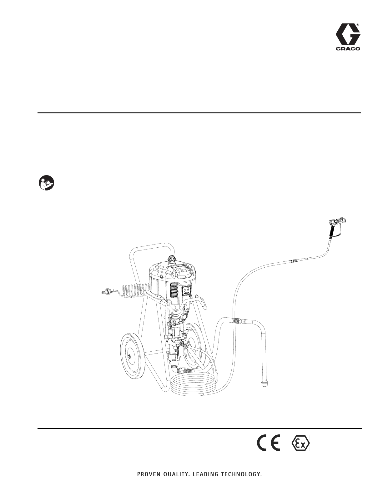
Instructions - Parts
Xtreme Packages
High performance, high pressure spray packages for protective coatings. For professional
use only.
Important Safety Instructions
Read all warnings and instructions in this manual.
Save these instructions.
See page 4 for model information and maximum working pressures.
311164M
EN
r_x25dh1_x45dl1_311164_1f
II 2 G
Page 2

Contents
Related Manuals . . . . . . . . . . . . . . . . . . . . . . . . . . . 3
Models . . . . . . . . . . . . . . . . . . . . . . . . . . . . . . . . . . . 4
Sprayer Packages . . . . . . . . . . . . . . . . . . . . . . . . 4
Specialty Sprayer Packages . . . . . . . . . . . . . . . . 5
Configurable Cart Packages . . . . . . . . . . . . . . . . 5
Pump Packages . . . . . . . . . . . . . . . . . . . . . . . . . 6
Warnings . . . . . . . . . . . . . . . . . . . . . . . . . . . . . . . . . 7
Component Identification - Cart Mount . . . . . . . . . 9
Component Identification - Wall Mount . . . . . . . . 10
System Components . . . . . . . . . . . . . . . . . . . . . 11
Grounding . . . . . . . . . . . . . . . . . . . . . . . . . . . . . . . 12
Setup . . . . . . . . . . . . . . . . . . . . . . . . . . . . . . . . . . . . 12
Pressure Relief Procedure . . . . . . . . . . . . . . . . . . 13
Trigger Lock . . . . . . . . . . . . . . . . . . . . . . . . . . . 13
Prime/Flush . . . . . . . . . . . . . . . . . . . . . . . . . . . . . . 14
Spray . . . . . . . . . . . . . . . . . . . . . . . . . . . . . . . . . . . . 16
Circulating Zinc Fluids . . . . . . . . . . . . . . . . . . . . 16
Shutdown . . . . . . . . . . . . . . . . . . . . . . . . . . . . . . . . 17
Maintenance . . . . . . . . . . . . . . . . . . . . . . . . . . . . . . 18
Preventive Maintenance Schedule . . . . . . . . . . 18
Daily Maintenance . . . . . . . . . . . . . . . . . . . . . . 18
Corrosion Protection . . . . . . . . . . . . . . . . . . . . . 18
Cart Maintenance . . . . . . . . . . . . . . . . . . . . . . . 18
DataTrak Controls and Indicators . . . . . . . . . . . . 19
DataTrak Operation . . . . . . . . . . . . . . . . . . . . . . . . 20
Setup Mode . . . . . . . . . . . . . . . . . . . . . . . . . . . . 20
Run Mode . . . . . . . . . . . . . . . . . . . . . . . . . . . . . 20
Troubleshooting . . . . . . . . . . . . . . . . . . . . . . . . . . 23
Xtreme Lower Removal . . . . . . . . . . . . . . . . . . . . . 24
Disconnect and Reconnect Lower . . . . . . . . . . 24
Wall Mount Assembly . . . . . . . . . . . . . . . . . . . . . . 26
Hopper Assembly . . . . . . . . . . . . . . . . . . . . . . . . . 26
Airless Xtreme Sprayer Parts . . . . . . . . . . . . . . . . 28
Wall Mount Xtreme Package Parts . . . . . . . . . . . . 29
Parts - Airless Xtreme Sprayer Packages . . . . . . 30
Component Parts - All Airless Sprayer Packages 30
Common Parts . . . . . . . . . . . . . . . . . . . . . . . . . 35
Air-Assisted Xtreme Sprayer Parts . . . . . . . . . . . 37
Zinc Xtreme Sprayer Parts . . . . . . . . . . . . . . . . . . 38
Parts - Air-Assisted and Zinc Sprayer Packages 39
Dura-Flo Sprayer Parts . . . . . . . . . . . . . . . . . . . . . 40
Parts - Dura-Flo Sprayer Packages . . . . . . . . . . . 41
Cart Parts . . . . . . . . . . . . . . . . . . . . . . . . . . . . . . . . 42
Heavy Duty Cart, Model 287884 . . . . . . . . . . . . 42
Light Weight Cart, Model 287919 . . . . . . . . . . . 42
Pump Package Parts . . . . . . . . . . . . . . . . . . . . . . . 43
Pump Packages with L085C# Lowers (80:1 ratio) 44
Pump Packages with L115C# Lowers (35:1, 55:1
ratio) . . . . . . . . . . . . . . . . . . . . . . . . . . . . . . . . . 45
Pump Packages with L145C# and L14AC1 Lowers
(31:1, 46:1, 90:1 ratio) . . . . . . . . . . . . . . . . . . . 46
Pump Packages with L180C# and L18AC1 Lowers
(24:1, 40:1, 70:1 ratio) . . . . . . . . . . . . . . . . . . . 47
Pump Packages with L220C# Lowers
(21:1, 30:1, 60:1 ratio) . . . . . . . . . . . . . . . . . . . 48
Pump Packages with L250C# Lowers (50:1 ratio) 49
Pump Packages with L290C# Lowers (16:1, 25:1,
45:1 ratio) . . . . . . . . . . . . . . . . . . . . . . . . . . . . . 50
Dimensions . . . . . . . . . . . . . . . . . . . . . . . . . . . . . . . 51
Weights . . . . . . . . . . . . . . . . . . . . . . . . . . . . . . . 53
Mounting Hole Diagram . . . . . . . . . . . . . . . . . . . . . 54
Wall Mount Bracket . . . . . . . . . . . . . . . . . . . . . . 54
Accessories . . . . . . . . . . . . . . . . . . . . . . . . . . . . . . 55
Technical Data . . . . . . . . . . . . . . . . . . . . . . . . . . . . 56
Pump Package Performance Charts . . . . . . . . . . 57
Graco Standard Warranty . . . . . . . . . . . . . . . . . . . 60
Graco Information . . . . . . . . . . . . . . . . . . . . . . . . . 60
2 311164M
Page 3
Related Manuals
Component Manuals in U.S. English:
Manual Description
Related Manuals
311762
311238
311239
311486
3A0293
The Xtreme Packages manual is available in the following languages. See the following chart for specific languages
and corresponding part numbers.
Manual Language
311164
312437
312438
312439
312440
312441
Xtreme Lower Instructions - Parts
NXT Air Motor Instructions - Parts
Integrated Air Control Modules for NXT Air Motors Instructions - Parts
DataTrak
Air Controls for Heavy and Light Duty Carts Instructions-Parts
™
Conversion Kit
English
Chinese
Dutch
Finnish
French
German
312442
312443
312444
312445
312446
312447
312448
312449
312450
Greek
Italian
Japanese
Korean
Portuguese
Russian
Spanish
Swedish
Turkish
311164M 3
Page 4
Models
Models
Sprayer Packages
Airless Sprayers, Wall Mount Packages, and Hopper Packages
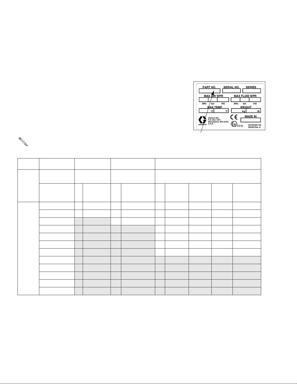
Check your sprayer, wall mount, or hopper package’s identification plate (ID) for
the 6-digit part number of your package. Use the following matrix to define the
construction of your package, based on the six digits. For example, Sprayer
Part Number X60D H 1 represents the Xtreme brand (X), pressure ratio
(60 :1), de-icing motor (D), heavy duty cart (H), and complete package (gun and
hose included) with DataTrak
Xtreme Sprayer Parts section starting on page 28. The digits in the matrix do
not correspond to the reference numbers in the Parts drawings and lists.
™
(1). To order replacement parts, see Airless
NOTE: All models have a maximum air input pressure of 100 psi (.7
MPa, 7 bar). Models with a 90:1 pressure ratio have a maximum air
input
pressure of 80 psi (0.55 MPa, 5.5 bar).
ID
X60 D H 1
Second and
Third Digit Fourth Digit Fifth Digit Sixth Digit
First
Digit
X
(Xtreme
brand)
Pressure Ratio
(xx:1)
25
30
35
40
45
46
50
55
60
70
80
90
Motor /
Exhaust Mount Option
D De-Icing H Heavy Duty 1
L Low Noise L Light Weight 2
W Wall Mount 3
Complete
Package DataTrak Hopper
✔✔
✔
✔
4
5
6
7
✔ ✔ ✔
✔ ✔
✔ ✔
Without
Integrated
Fluid Filter
4 311164M
Page 5
Specialty Sprayer Packages
Models
Wall Mount Package 287978
Model 287978 is a 40:1 ratio unit that includes a low
noise motor, DataTrak, external filter, and no gun or
hose.
Air-Assisted Sprayers
All air-assisted sprayers include a de-icing motor, a
heavy duty cart, G40 spray gun, and hose.
30:1 Pressure Ratio - 287975
40:1 Pressure Ratio - 287976
Zinc Sprayers
All zinc sprayers include a de-icing motor and a heavy
duty cart. Models 287973 and 287974 also include Silver spray gun and hose.
25:1 Pressure Ratio - 287971
40:1 Pressure Ratio - 287972
25:1 Pressure Ratio - 287973
40:1 Pressure Ratio - 287974
Dura-Flo™ Sprayers
All Dura-Flo sprayers include a de-icing motor, a heavy
duty cart, and Dura-Flo pump package. Only model
287980 includes a gun and hose.
23:1 Pressure Ratio - 287979
23:1 Pressure Ratio - 287980
32:1 Pressure Ratio - 287981
Configurable Cart Packages
NOTE: Configurable cart packages do not
include lowers. Pair these packages with any
Xtreme lower (145cc - 290cc) for a sprayer package.
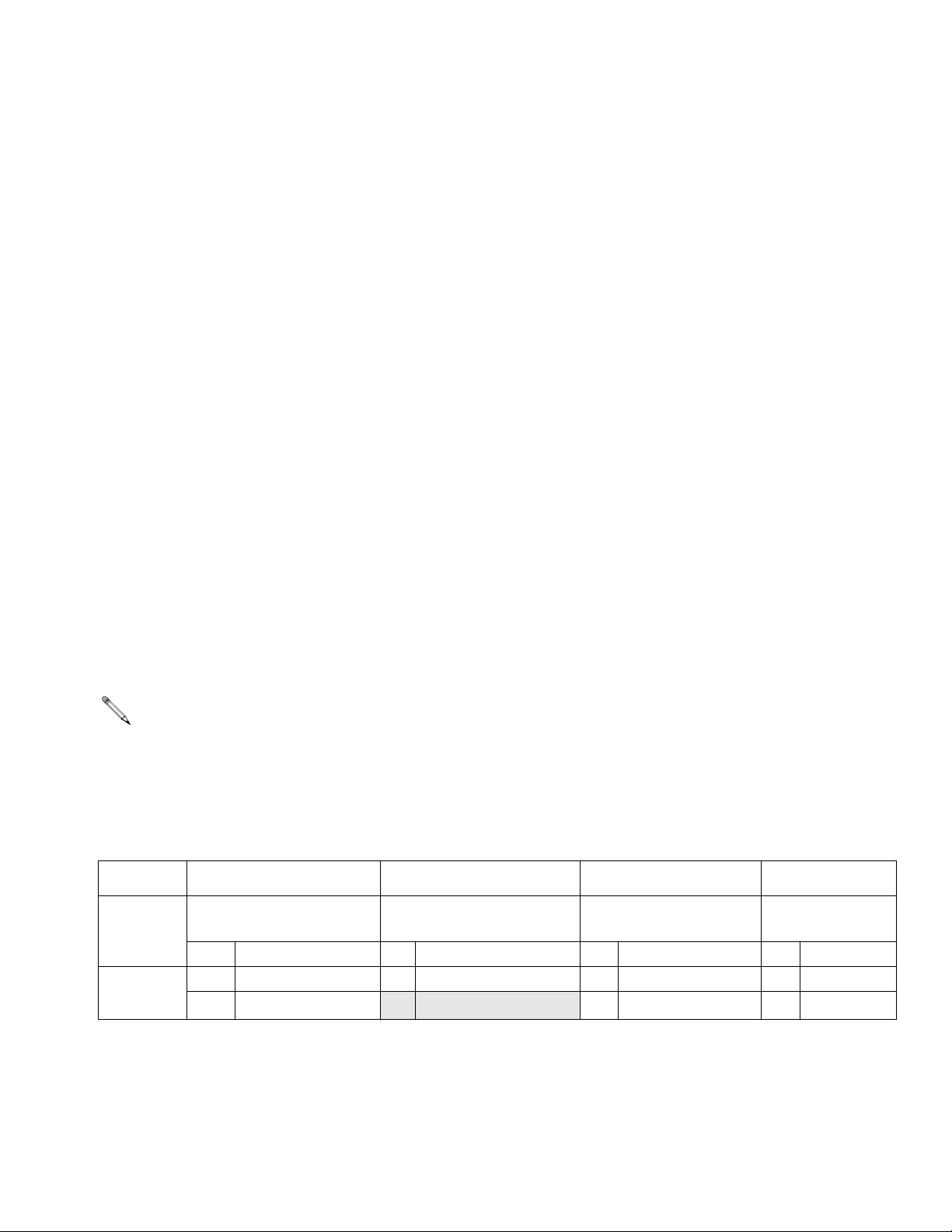
All models include air controls, tie rods, coupling kit, and suction hose. Use the following matrix to define the construction of your cart package, based on the six digits. For example, cart package number XN3D H 2 represents the
™
Xtreme brand (X), motor (NXT3400), de-icing motor (D), heavy duty cart (H), and bare package with DataTrak
(2).
XN3 D H 2
Second and
First Digit
X
(Xtreme
brand)
N3
N6
Third Digit Fourth Digit Fifth Digit Sixth Digit
Motor Exhaust Mount Option DataTrak
NXT3400
NXT6500
D De-Icing H Heavy Duty
L Light Weight
2
4
✔
311164M 5
Page 6
Models
Pump Packages
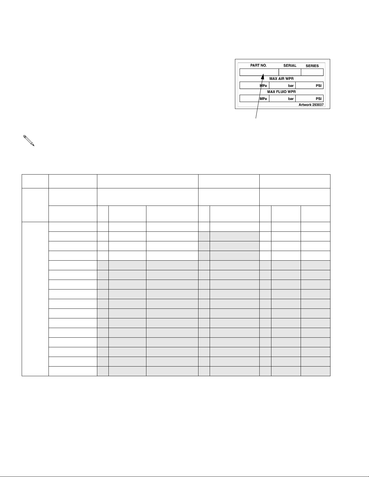
Check your pump package’s identification plate (ID) for the 6-digit part number
of your pump package. For example, Pump Part Number P30M C 1 rep-
resents the pump (P), pressure ratio (30 :1), low noise exhaust motor with
DataTrak
™
(M), carbon steel construction (C), and no built-in filter or air con-
trols (1). For
To order replacement parts, see Pump Package Parts section starting on
page 43. The digits in the matrix do not correspond to the reference numbers
in the Parts drawings and lists.
ID
NOTE: Models with 16:1 - 70:1 pressure ratios have a maximum air
input pressure of 100 psi (.7 MPa, 7 bar). Models with a 90:1 pressure ratio have a maximum air input pressure of 80 psi (0.55 MPa,
5.5 bar).
P30 M C 1
Second and
First
Digit
P
(pumps)
Third Digit Fourth Digit Fifth Digit Sixth Digit
Pressure Ratio
(xx:1) Exhaust Communication
16
21
24
25
D De-Icing none C Carbon Steel 1
E De-Icing DataTrak 2
L Low Noise none 3
M Low Noise DataTrak 4
Lower
Construction
Built-in
Filter
✔
✔✔
30
31
35
40
45
46
50
55
60
70
80
90
Air
Controls
✔
6 311164M
Page 7
Warnings
Warnings
The following warnings are for the setup, use, grounding, maintenance, and repair of this equipment. The exclamation point symbol alerts you to a general warning and the hazard symbols refer to procedure-specific risks. Refer
back to these Warnings. Additional, product-specific warnings may be found throughout the body of this manual
where applicable.
WARNING
FIRE AND EXPLOSION HAZARD
Flammable fumes, such as solvent and paint fumes, in work area can ignite or explode. To help prevent
fire and explosion:
• Use equipment only in well ventilated area.
• Eliminate all ignition sources; such as pilot lights, cigarettes, portable electric lamps, and plastic drop
cloths (potential static arc).
• Keep work area free of debris, including solvent, rags and gasoline.
• Do not plug or unplug power cords, or turn power or light switches on or off when flammable fumes
are present.
• Ground all equipment in the work area. See Grounding instructions.
• Use only grounded hoses.
• Hold gun firmly to side of grounded pail when triggering into pail.
• If there is static sparking or you feel a shock, stop operation immediately. Do not use equipment
until you identify and correct the problem.
• Keep a working fire extinguisher in the work area.
BATTERY HAZARD
Sparking can occur when changing batteries. The battery may cause an explosion if mishandled:
• You must use the battery type specified for use with the equipment.
• Only replace the battery in a non-hazardous location, away from flammable fluids or fumes.
SKIN INJECTION HAZARD
High-pressure fluid from gun, hose leaks, or ruptured components will pierce skin. This may look like just
a cut, but it is a serious injury that can result in amputation. Get immediate surgical treatment.
• Do not point gun at anyone or at any part of the body.
• Do not put your hand over the spray tip.
• Do not stop or deflect leaks with your hand, body, glove, or rag.
• Do not spray without tip guard and trigger guard installed.
• Engage trigger lock when not spraying.
•Follow Pressure Relief Procedure in this manual, when you stop spraying and before cleaning,
checking, or servicing equipment.
311164M 7
Page 8
Warnings
WARNING
EQUIPMENT MISUSE HAZARD
Misuse can cause death or serious injury.
• Do not operate the unit when fatigued or under the influence of drugs or alcohol.
• Do not exceed the maximum working pressure or temperature rating of the lowest rated system
component. See Technical Data in all equipment manuals.
• Use fluids and solvents that are compatible with equipment wetted parts. See Technical Data in all
equipment manuals. Read fluid and solvent manufacturer’s warnings. For complete information
about your material, request MSDS forms from distributor or retailer.
• Check equipment daily. Repair or replace worn or damaged parts immediately with genuine Graco
replacement parts only.
• Do not alter or modify equipment.
• Use equipment only for its intended purpose. Call your Graco distributor for information.
• Route hoses and cables away from traffic areas, sharp edges, moving parts, and hot surfaces.
• Do not kink or over bend hoses or use hoses to pull equipment.
• Keep children and animals away from work area.
• Comply with all applicable safety regulations.
MOVING PARTS HAZARD
Moving parts can pinch or amputate fingers and other body parts.
• Keep clear of moving parts.
• Do not operate equipment with protective guards or covers removed.
• Pressurized equipment can start without warning. Before checking, moving, or servicing equipment,
follow the Pressure Relief Procedure in this manual. Disconnect power or air supply.
TOXIC FLUID OR FUMES HAZARD
Toxic fluids or fumes can cause serious injury or death if splashed in the eyes or on skin, inhaled, or
swallowed.
• Read MSDS’s to know the specific hazards of the fluids you are using.
• Store hazardous fluid in approved containers, and dispose of it according to applicable guidelines.
PERSONAL PROTECTIVE EQUIPMENT
You must wear appropriate protective equipment when operating, servicing, or when in the operating
area of the equipment to help protect you from serious injury, including eye injury, inhalation of toxic
fumes, burns, and hearing loss. This equipment includes but is not limited to:
• Protective eyewear
• Clothing and respirator as recommended by the fluid and solvent manufacturer
•Gloves
• Hearing protection
8 311164M
Page 9
Component Identification - Cart Mount
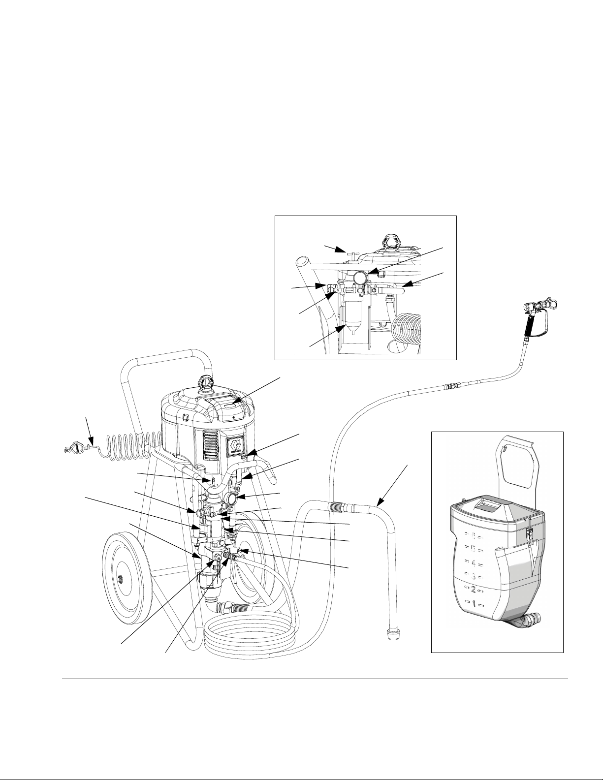
Component Identification - Cart Mount
A Air Inlet, 3/4 npt(f)
B Bleed Type Master Air Valve (required)
C Air Pressure Relief Valve
D Air Filter (hidden)
E Air Pressure Gauge
F Air Regulator Adjustment Knob
GDataTrak
models)
J Fluid Drain/Purge Valve (required)
™
location (see page 19; not present on all
Light Duty Cart
K Fluid Filter
L Grounding Wire (required)
M Lower
N Suction Hose and Tube
P Fluid Outlet
R Optional Fluid Outlet, for second gun
S Packing Nut
T De-Ice Control
Heavy Duty Cart
F
A
C
D
G
E
B
L
F
S
A
M
R
P
FIG. 1: Airless Sprayer
T
B
E
C
D
K
J
N
TI8408a
Hopper (288347) Option
r_x25dh1_x45dl1_311164_1f
311164M 9
Page 10
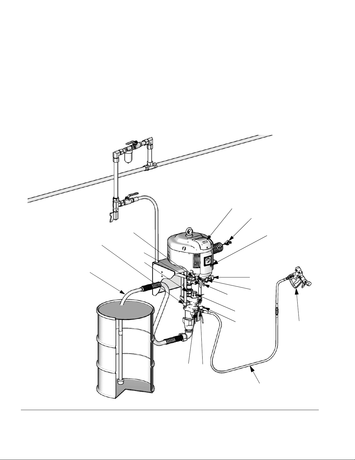
Component Identification - Wall Mount
Component Identification - Wall Mount
A Air Inlet, 3/4 npt(f)
B Bleed Type Master Air Valve (required)
C Air Pressure Relief Valve
D Air Filter (hidden)
E Air Pressure Gauge
F Air Regulator Adjustment Knob
GDataTrak
models)
J Fluid Drain/Purge Valve (required)
K Fluid Filter
™
location (see page 19; not present on all
M
L Grounding Wire (required)
M Lower
N Suction Hose and Tube
P Fluid Outlet
R Optional Fluid Outlet, for second gun
S Packing Nut
T De-Ice Control
U Spray Gun
VHose
G
L
A
T
B
S
N
FIG. 2: Wall Mount System
F
E
C,D
K
J
R
P
U
V
TI8413a
10 311164M
Page 11
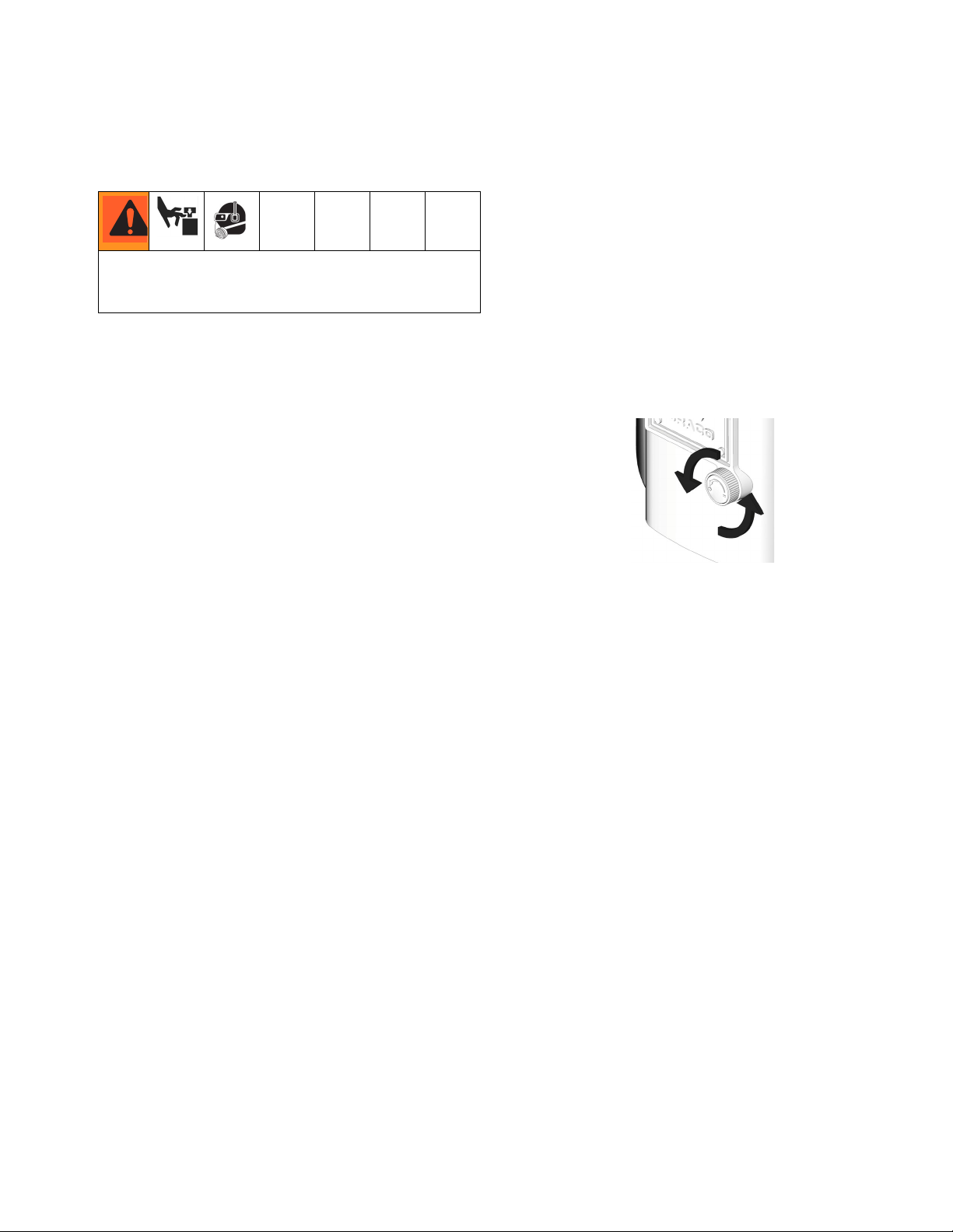
System Components
Component Identification - Wall Mount
* Bleed Type Master Air Valve (B)
Trapped air can cause the pump to cycle unexpectedly,
which could result in serious injury from splashing or
moving parts.
• Be sure the valve is easily accessible from the pump
and located downstream from the air regulator.
• Required in your system to relieve air trapped
between it and the air motor when the valve is
closed.
• Open to supply air to the motor.
• Close to shut off air to the motor, and bleed any
trapped air from the motor.
* Air Pressure Relief Valve (C)
Automatically opens to relieve air pressure if supplied
pressure exceeds preset limit.
Air Regulator Adjustment (F)
Adjusts air pressure to the motor and fluid outlet pressure of pump. Locate it close to the pump. Read air
pressure on gauge (E).
* Fluid Drain/Purge Valve (J)
Open valve to relieve pressure and when flushing or
priming pump. Close valve when spraying.
De-Ice Control (T)
Turn knob (open) to reduce icing.
TI8160b
* Required system components.
Air Filter (D)
Removes harmful dirt from compressed air supply.
311164M 11
Page 12
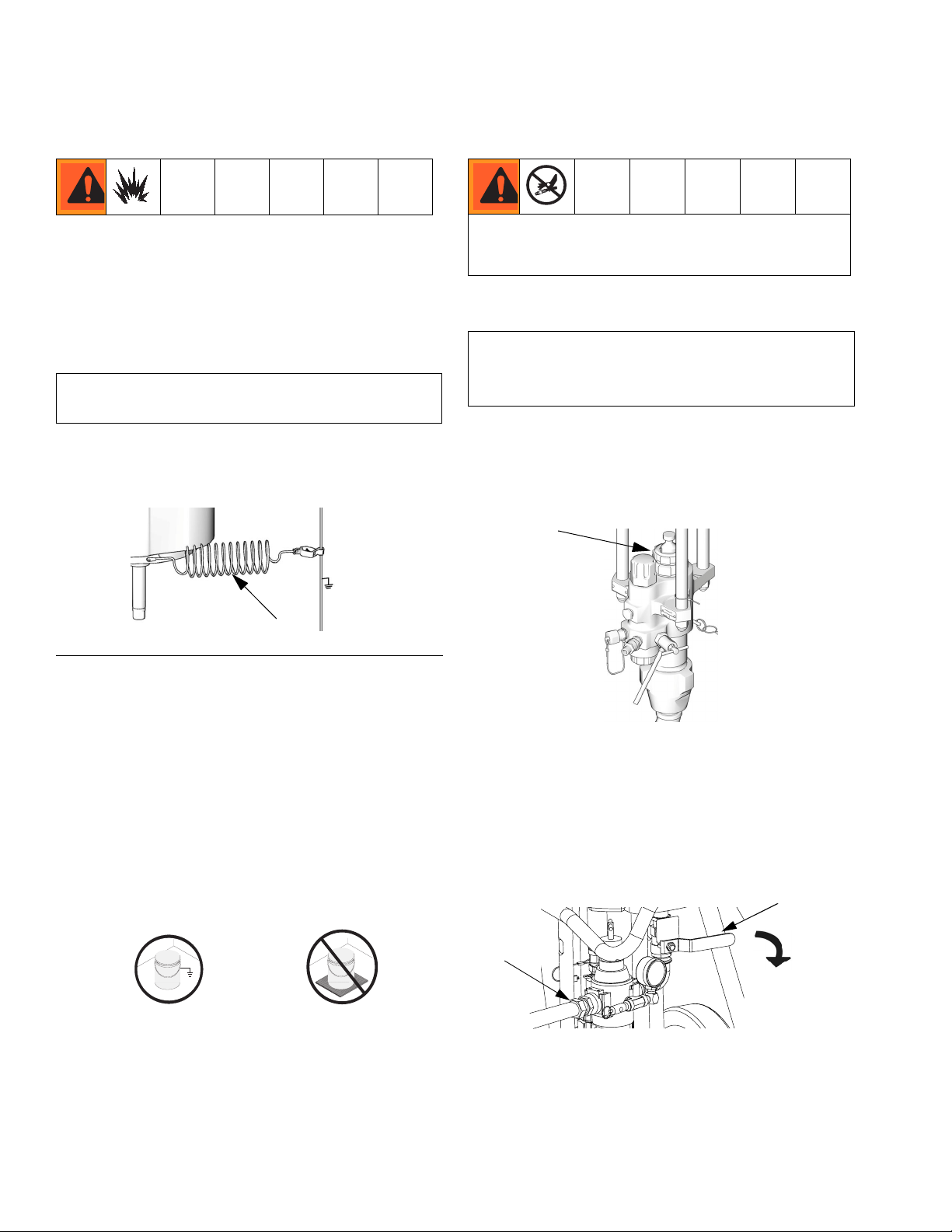
Grounding
Grounding
The equipment must be grounded. Grounding reduces
the risk of static and electric shock by providing an
escape wire for the electrical current due to static build
up or in the event of a short circuit.
Table 1: Tools Required
• Grounding wires and clamps for pails
• Two 5 gal. (19 liter) metal pails
1. Connect the ground wire (244524) (L) to the ground
stud on the air motor.
Setup
To avoid tip over, ensure cart is on a flat and level surface. Failure to do so could result in injury or equipment damage.
Table 2: Tools Required
• Two adjustable wrenches
• Non-sparking hammer or plastic mallet
• Torque wrench
1. Ground sprayer.
2. Check packing nut (S). Fill with Throat Seal Liquid
(TSL). Torque to 25-30 ft-lb (34-41 N•m).
S
L
F
IG
. 3
2. Connect the other end of the ground wire to a true
earth ground.
3. Ground the object being sprayed, fluid supply container, and all other equipment in the work area. Follow your local code. Use only electrically conductive
air and fluid hoses.
4. Ground all solvent pails. Use only metal pails, which
are conductive, placed on a grounded surface. Do
not place pail on a nonconductive surface, such as
paper or cardboard, which interrupts grounding continuity.
TI1102-1
TI8250a
TI1102-2
TI8316a
3. Attach electrically conductive fluid hose to pump
outlet and tighten.
4. Attach electrically conductive fluid hose (and air
hose if using an AA gun) to gun and tighten.
5. Close bleed type master air valve (B). Connect air
supply hose to 3/4 npt(f) air inlet (A).
B
A
6. Flush before using. See page 14.
7. Prime before using. See page 14.
12 311164M
Page 13
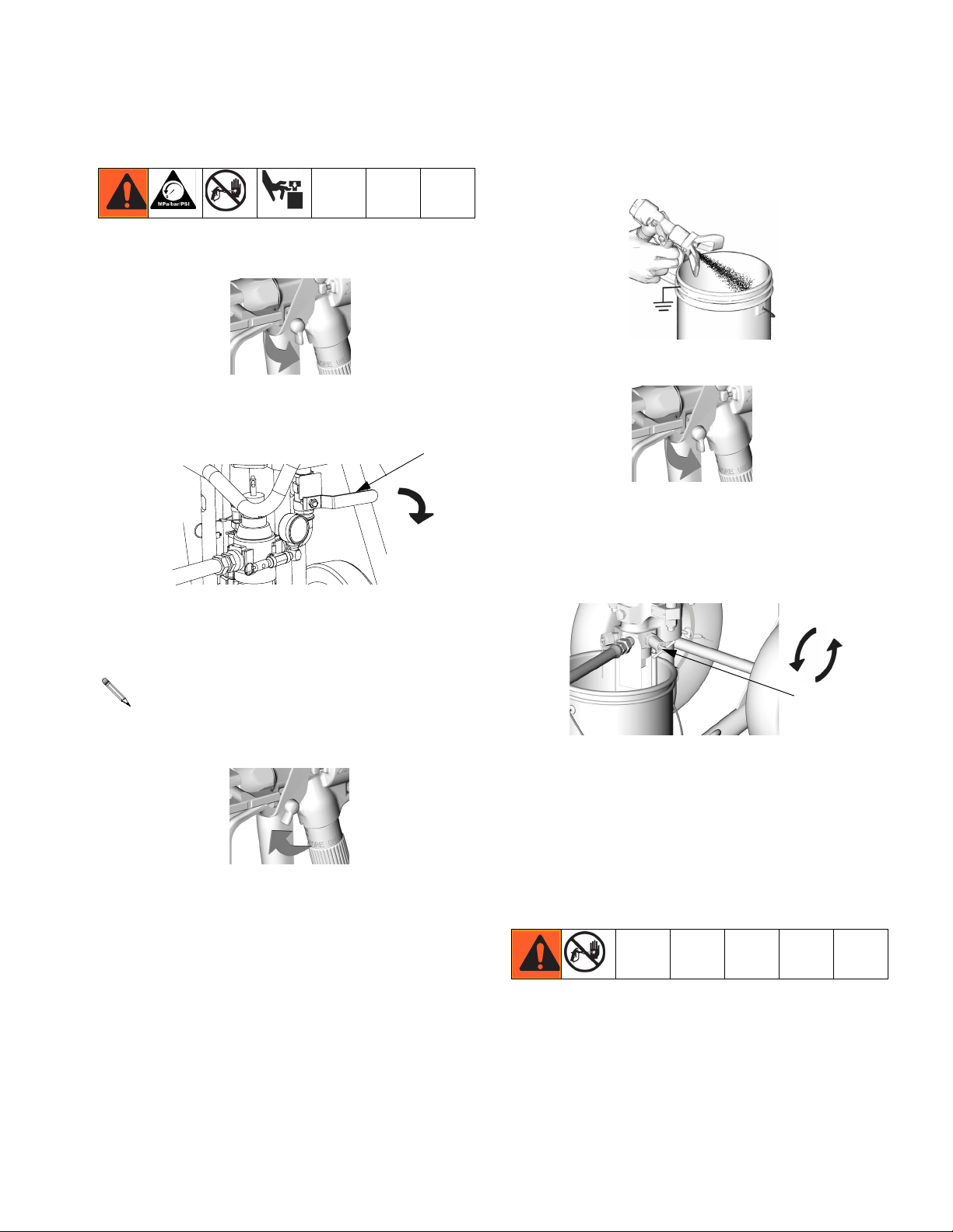
Pressure Relief Procedure
1. Engage gun trigger lock.
Pressure Relief Procedure
4. Hold gun firmly against a grounded metal pail. Trigger the gun.
TI8252a
TI5049a
2. Close bleed type master air valve (B).
3. Disengage gun trigger lock.
NOTE: If using an AA gun, turn gun air regulator
counter-clockwise to relieve pressure.
TI5048a
5. Engage gun trigger lock.
B
TI5049a
6. Drain fluid. To drain fluid, slowly open all fluid drain
valves, including drain/purge valve (J), in system
into a waste pail. If there is a return tube, open
return line ball valve.
+
J
TI8417a
7. If you suspect the spray tip or hose is completely
clogged, or that pressure has not been fully relieved
after following the previous steps, very slowly loosen
the tip guard retaining nut or hose end coupling and
relieve pressure gradually; then loosen completely.
With tip removed, trigger gun into bucket.
Trigger Lock
Always engage gun trigger lock when you stop spraying
to prevent gun from being triggered accidentally by hand
or if dropped or bumped.
311164M 13
Page 14
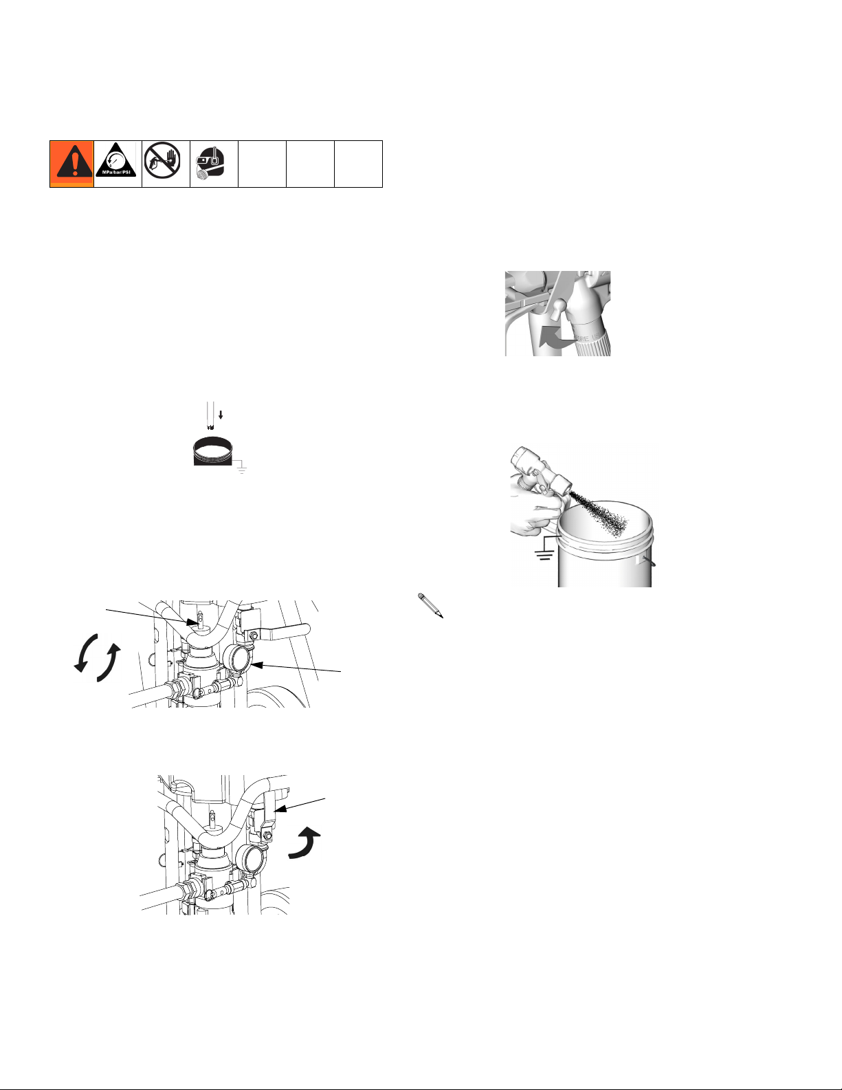
Prime/Flush
Prime/Flush
1. Follow Pressure Relief Procedure, page 13.
2. Remove tip and tip guard from gun.
3. Flushing only: If desired, remove built-in fluid filter
(present on some models). Reinstall filter cap after
removing fluid filter.
4. Place suction tube in a compatible fluid (if priming)
or solvent (if flushing).
Zinc sprayers only: Place return tube in a compatible fluid (if priming) or solvent (if flushing). Open
return line valve.
5. Turn regulator adjustment knob (G) counterclockwise until it stops, and gauge (E) reads zero.
G
7. Prime or flush hose and gun:
a. Disengage gun trigger lock.
TI5048a
b. Trigger gun into grounded pail until a steady
stream comes from gun. If flushing, trigger gun
for 10-15 seconds.
TI8727a
NOTE: If using an AA gun, increase air pressure
by turning gun regulator clockwise.
-
E
6. Open bleed type master air valve (B).
B
Zinc sprayers only: When clean solvent or fluid flows
from return tube, close return line valve. Pump will
stall.
14 311164M
c. Engage trigger lock.
8. If priming, equipment is now ready to spray; go to
Spray, page 16.
If flushing, proceed with step 9.
Page 15
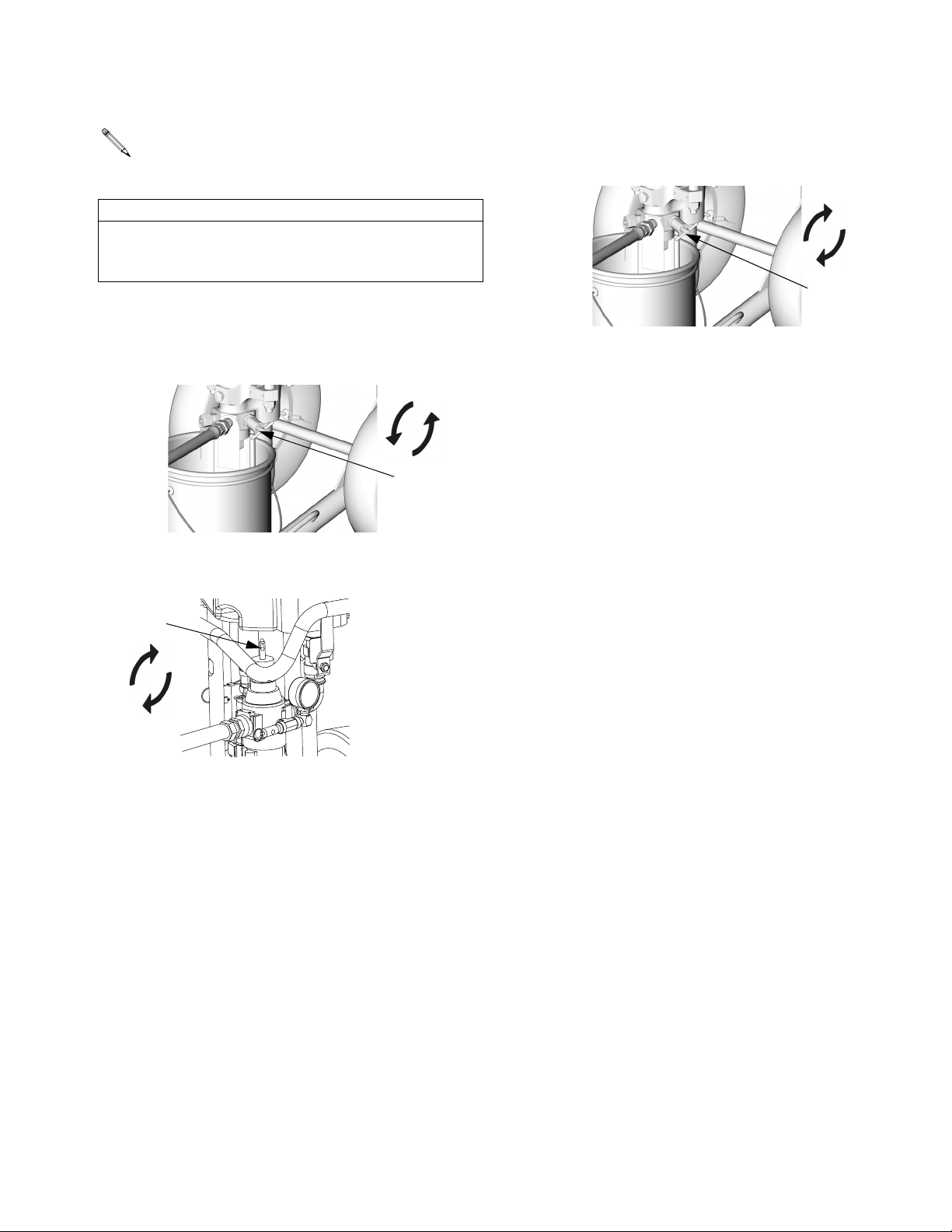
Prime/Flush
NOTE: The remaining steps are for flushing
only.
CAUTION
Do not prime pump through drain/purge valve using
two component materials. Mixed two-component
materials will harden in valve and result in clogging.
9. Place drain tube in a grounded waste pail.
Open drain/purge valve (J) slightly by rotating counterclockwise.
+
J
TI8417a
10. Start the pump by rotating the air regulator adjustment knob (G) clockwise until pump begins to move.
11. When clean solvent flows from drain tube close
drain/purge valve (J) by rotating clockwise. Pump
will stall.
-
J
TI8417a
12. Follow Pressure Relief Procedure, page 13. Leave
solvent in and store sprayer.
+
G
311164M 15
Page 16
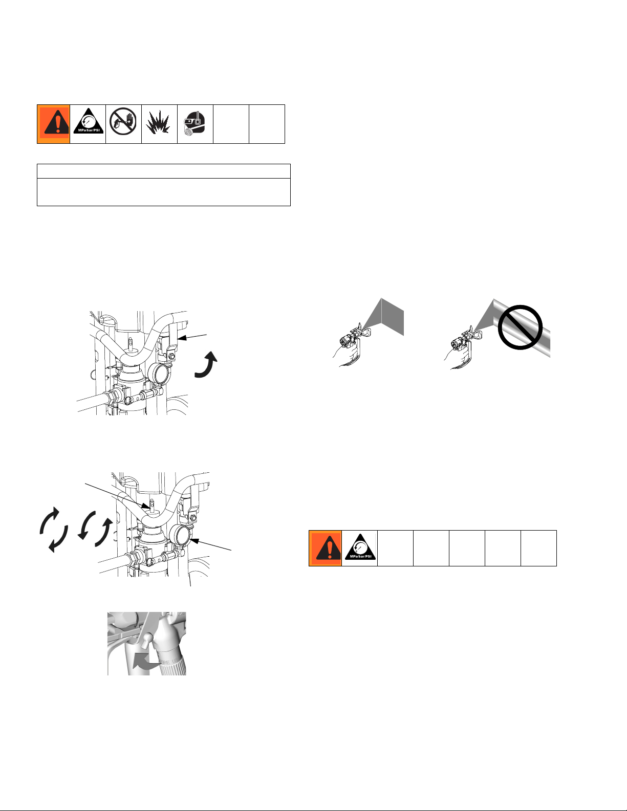
Spray
Spray
CAUTION
Do not allow pump to run dry. It will quickly accelerate
to a high speed causing damage.
1. Prime. See Prime/Flush, page 14.
2. Follow Pressure Relief Procedure, page 13.
3. Install tip and tip guard on gun.
4. Open bleed type master air valve (B).
B
5. Turn regulator adjustment knob (G) until gauge (E)
reads desired pressure. Turn clockwise to increase
pressure, counterclockwise to decrease pressure.
G
+
-
7. Spray a test pattern. Read fluid manufacturer’s recommendations. Adjust as necessary. If using an AA
gun, increase gun air pressure while testing spray
pattern.
8. Zinc sprayers only: When not spraying, reduce air
pressure to 30 psi (2.1 MPa, 21 bar). Open return
line and close gun valve.
9. Flush when done spraying. See Prime/Flush, page
14.
10. Follow Pressure Relief Procedure, page 13.
Circulating Zinc Fluids
E
6. Disengage gun trigger lock.
TI5048a
16 311164M
1. When spraying zinc fluids, close return line valve.
Circulation is not required when spraying.
2. To circulate fluid back to supply container while you
are not spraying, open return line valve and lock gun
trigger safety. Pump will continue to run.
3. Always relieve pressure before overnight shut-
down, when changing spray tips, or when checking
or servicing any part of system. During circulation,
some fluid will be present in gun line and must be
relieved.
Page 17
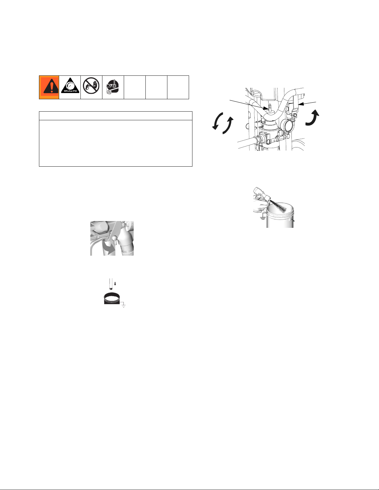
Shutdown
Shutdown
5. Open bleed type master air valve (B). Turn regulator
adjustment knob (G) counterclockwise to lowest
possible fluid pressure.
CAUTION
Never leave water or water-base fluid in pump overnight. If you are pumping water-base fluid, flush with
water first, then with a rust inhibitor, such as mineral
spirits solvent (also called white spirit). Relieve pressure, but leave rust inhibitor in pump to protect parts
from corrosion.
1. Follow Pressure Relief Procedure, page 13.
2. Remove tip and tip guard from gun.
3. Engage gun trigger lock.
TI5049a
4. Place siphon tube in grounded metal pail containing
cleaning fluid.
G
B
-
6. Hold a metal part of the gun firmly to a grounded
metal pail. Trigger the gun until clean solvent dispenses.
TI8727a
7. Follow Pressure Relief Procedure, page 13.
311164M 17
Page 18
Maintenance
Maintenance
Preventive Maintenance Schedule
The operating conditions of your particular system
determine how often maintenance is required. Establish
a preventive maintenance schedule by recording when
and what kind of maintenance is needed, and then
determine a regular schedule for checking your system.
Daily Maintenance
NOTE: For overnight shutdown, stop pump at
bottom of its stroke to prevent fluid from drying
on exposed displacement rod and damaging
throat packings. Follow Pressure Relief Procedure, page 13.
1. Flush. See Prime/Flush, page 14.
Corrosion Protection
Always flush the pump before the fluid dries on the displacement rod. Never leave water or water-based fluid in
the pump overnight. First, flush with water or a compatible solvent, then with mineral spirits solvent (also called
white spirit). Relieve the pressure, but leave the mineral
spirits solvent (also called white spirit) in the pump to
protect the parts from corrosion.
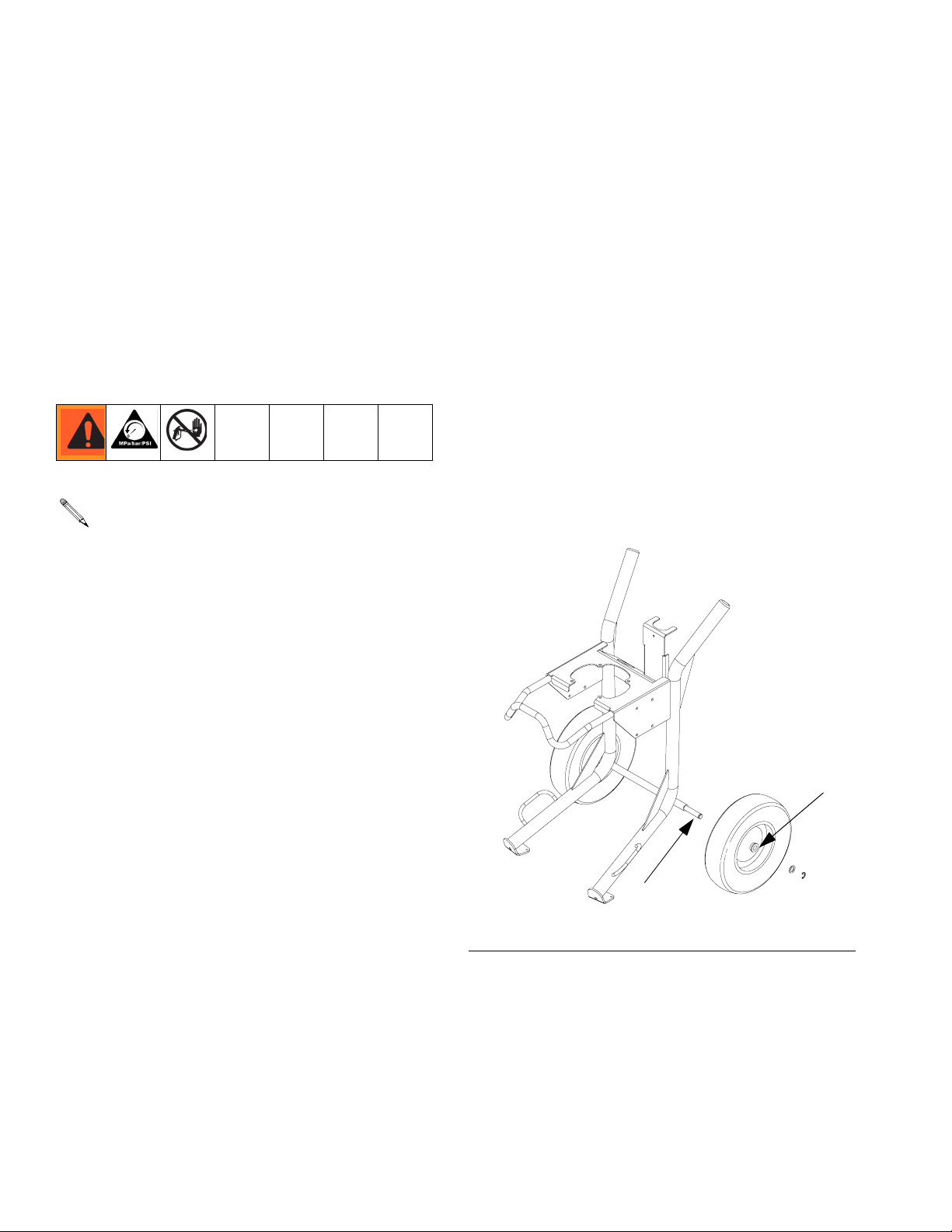
Cart Maintenance
Periodically lubricate the axle between points A and B
with lightweight oil. See F
Keep the cart clean by wiping up spills daily, using a
compatible solvent.
IG
. 4.
2. Relieve pressure. See Pressure Relief Procedure,
page 13.
3. Check packing nut (S, F
replace TSL as necessary. Torque to 25-30 ft-lb
(34-41 N•m).
4. Drain water from air filter.
5. Clean suction tube using a compatible solvent. It is
recommended that you clean the outside of the
sprayer using a cloth and compatible solvent.
6. Check hoses, tubes, and couplings. Tighten all fluid
connections before each use.
7. Clean fluid line filter.
IG
. 1). Adjust packings and
B
A
r_x25dh1_x45dh1_311164_38f
FIG. 4: Cart Assembly - Heavy Duty Model Shown
18 311164M
Page 19
DataTrak Controls and Indicators
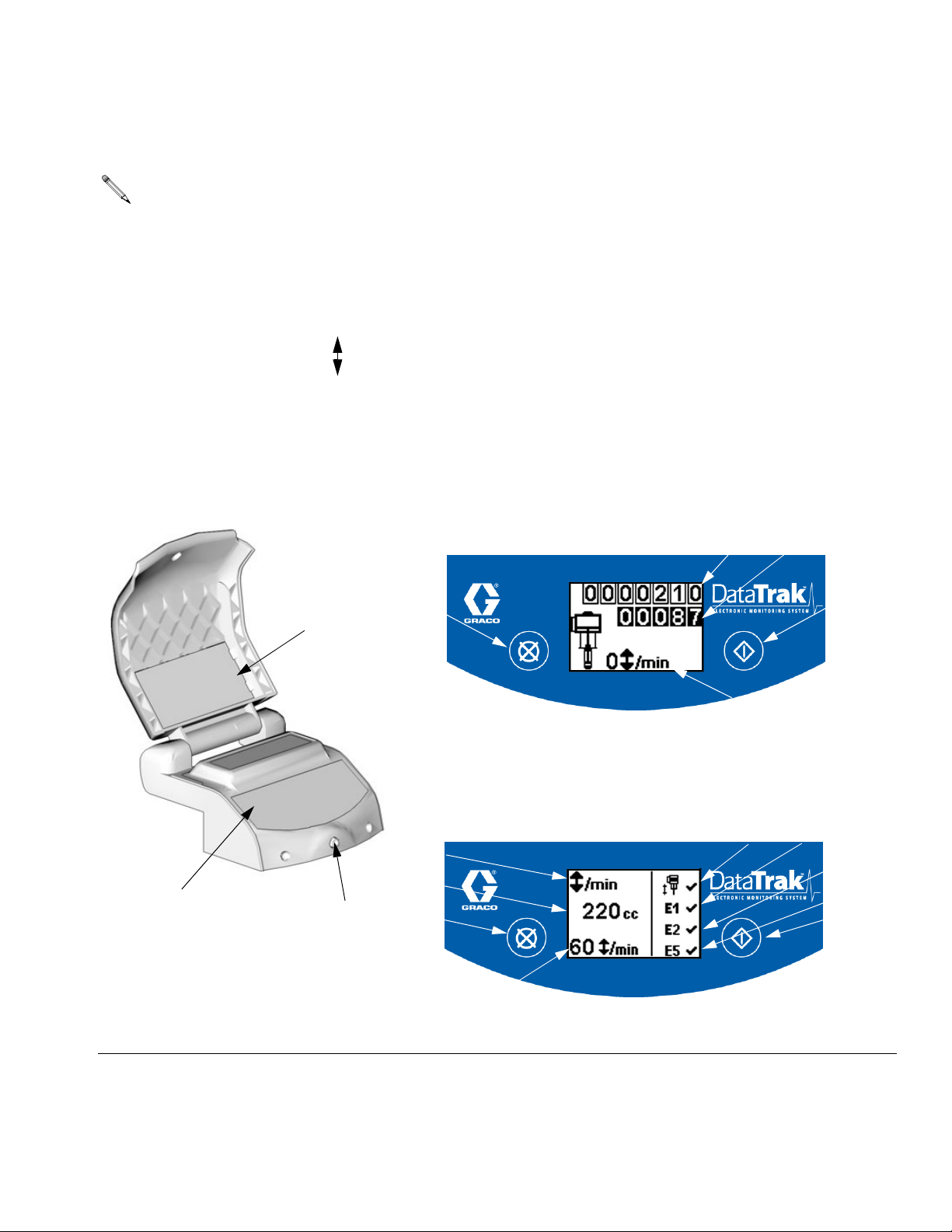
NOTE: DataTrak is included with certain models. See Models, page 4, for a list of models featuring DataTrak.
Key for FIG. 5
DataTrak Controls and Indicators
T Runaway Limit, in cycles per minute (user settable;
00=OFF)
U Lower Displacement (user settable)
V Flow Rate Units (user settable to gpm [US], gpm
[Imperial], oz/min [US], oz/min [Imperial], l/min, or cc/min)
W LED (fault indicator when lit)
X Diagnostic Reference Card (see T
Y Display
PF Prime/Flush Key (Enables Prime/Flush mode. While in
Prime/Flush mode, runaway protection is disabled and the
batch totalizer (BT) will not count.)
/min,
ABLE
3, page 22)
RK
X
RK Reset Key (Resets faults. Press and hold for 3 seconds to
clear the batch totalizer.)
CF Cycle/Flow Rate
BT Batch Totalizer
GT Grand Totalizer
RT Runaway Toggle (enable/disable)
UT E1 Error Option (enable/disable)
DT E2 Error Option (enable/disable)
ST E5 Error Option (enable/disable)
Run Mode
GT
BT
PF
CF
TI8622b
Setup Mode
RT
UT
V
DT
U
Y; See Details at right.
TI8215a
W
RK
T
ST
PF
TI8623b
FIG. 5. DataTrak Controls and Indicators
311164M 19
Page 20
DataTrak Operation
DataTrak Operation
NOTE: To prevent damage to the DataTrak soft
key buttons, do not press the buttons with
sharp objects such as pens, plastic cards, or
fingernails.
NOTE: DataTrak is included with certain models. See Models, page 4, for a list of models featuring DataTrak.
NOTE: The DataTrak display (Y) will turn off
after 1 minute to save battery life. Press any key
to wake up the display.
Setup Mode
1. See FIG. 5. Press and hold for 5 seconds until
Setup menu appears.
2. To enter settings for runaway, lower size, and flow
rate units, and to enable runaway, E1, E2, and E5
error options, press to change the value, then
Run Mode
Runaway
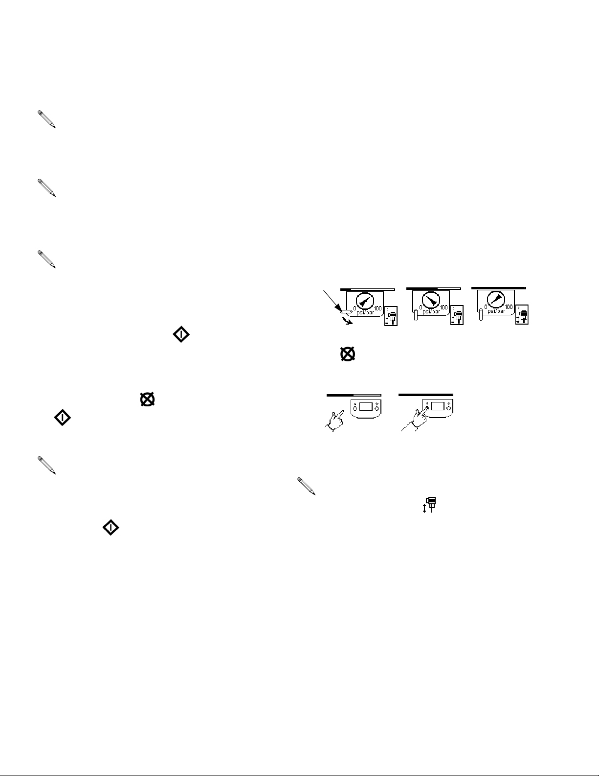
1. See FIG. 5. If pump runaway occurs, the runaway
solenoid will actuate, stopping the pump. The LED
(W) will flash and the display (Y) will indicate a runaway condition (see Table 3).
2. To reset runaway monitor, close master air valve (B).
Wait for air to completely bleed off the air motor
before going to step 3. The screen will change to
indicate this, as shown below.
B
3. Press to clear the diagnostic code and reset the
runaway solenoid.
to save the value and move the cursor to the
next data field.
NOTE: When runaway, E1, E2, and E5 error
options are enabled, a ✓ will appear on the
setup screen. See F
3. Move the cursor to the E5 error enable option field,
then press once more to exit Setup mode.
IG
. 5.
4. Open master air valve (B) to restart pump.
NOTE: To disable runaway monitoring, go to
setup mode and set runaway value (T) to 0
(zero) or disable (RT) (see F
IG
. 5).
20 311164M
Page 21
DataTrak Operation
Prime/Flush
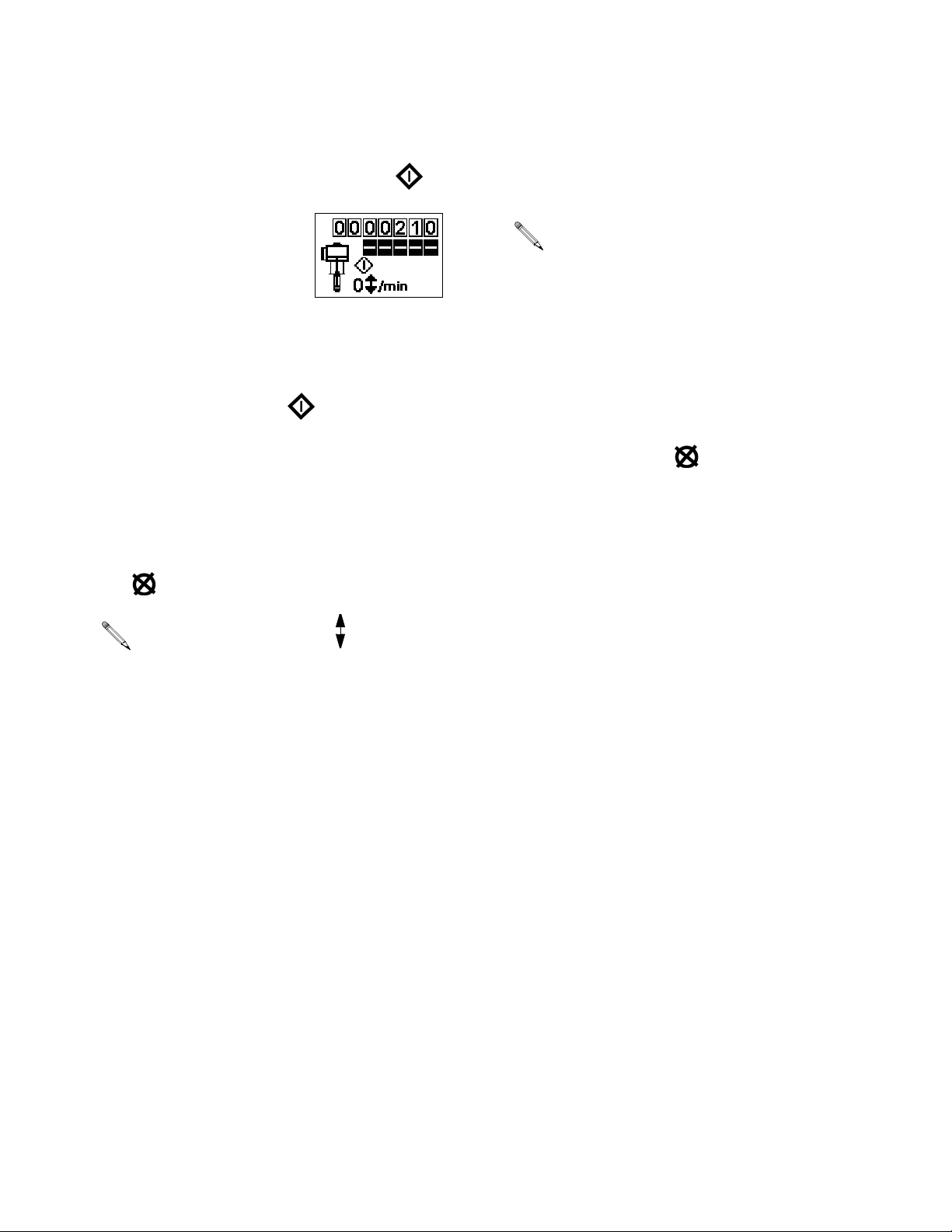
1. See FIG. 5. To enter Prime/Flush mode, press any
key to wake up the display, then press . The
Prime/Flush symbol will appear flashing in the dis-
play and the LED will flash .
2. While in Prime/Flush mode, runaway protection is
disabled and the batch totalizer (BT) will not count.
3. To exit Prime/Flush mode, press any key to wake up
the display, then press . The Prime/Flush symbol will disappear from the display and the LED will
stop flashing.
Counter/Totalizer
See FIG. 5. The last digit of the batch totalizer (BT) represents tenths of gallons or liters. To reset the totalizer,
press any key to wake up the display, then press and
hold for 3 seconds.
Display
See FIG. 5. The display (Y) will turn off after 1 minute of
inactivity in Run mode or 3 minutes in Setup mode.
Press any key to wake up the display.
NOTE: DataTrak will continue to count cycles
when display is off.
Diagnostics
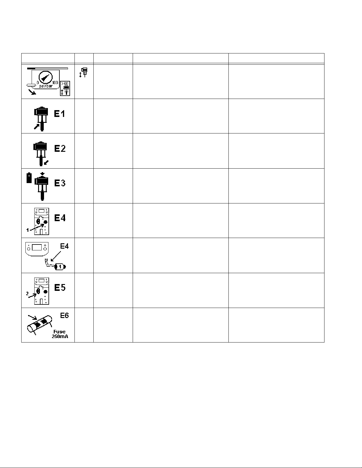
DataTrak can diagnose several problems with the pump.
When the monitor detects a problem, the LED (W, F
5) will flash and a diagnostic code will appear on the display. See Table 3.
To acknowledge the diagnosis and return to the normal
operating screen, press once to wake up the display,
and once more to clear the diagnostic code screen.
IG
.
NOTE: If flow rate is set to both totaliz-
ers will display the number of pump cycles.
/min,
311164M 21
Page 22
DataTrak Operation
Table 3: Diagnostic Codes
Symbol Code Code Name Diagnosis Cause
Runaway Pump running faster than set runaway
limit.
E-1 Diving Up Leak during upstroke. Worn piston valve or packings.
E-2 Diving Down Leak during downstroke. Worn intake valve.
• Increased air pressure.
• Increased fluid output.
• Exhausted fluid supply.
E-3 Low Battery Battery voltage too low to stop
runaway.
E-4 Service
Component 1
E-4 Disconnected
Solenoid
E-5 Service
Component 2
E-6 Blown Fuse Fuse is blown. • Faulty solenoid or solenoid wiring.
Problem with stopping runaway. • Damaged solenoid.
Solenoid is disconnected. • Solenoid unplugged.
Problem with sensing valve movement. • Sensors unplugged.
Low battery. To replace battery, see
manual 311238.
• Damaged valve carriage.
• Damaged solenoid wires.
• Sensors mounted incorrectly.
• Damaged sensors.
• Damaged valve carriage.
• Extreme temperatures (above 140°F
[60°C]).
22 311164M
Page 23
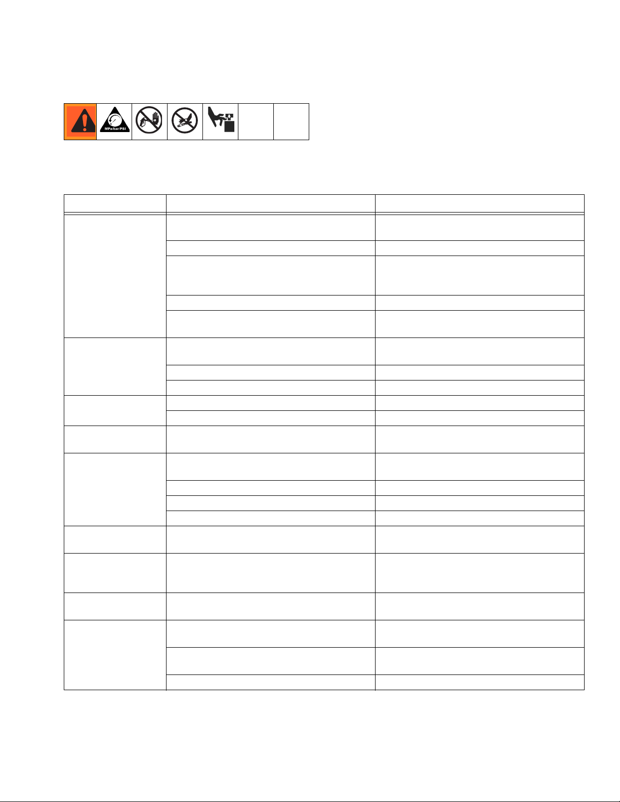
Troubleshooting
Troubleshooting
1. Follow Pressure Relief Procedure, page 13. 2. Check all possible causes and problems before dis-
assembling pump.
Problem Cause Solution
Does not operate. Valve closed or clogged. Clear air line; increase air supply. Check that
valves are open.
Fluid hose or gun obstructed. Clean hose or gun.*
Dried fluid on displacement rod. Clean rod; always stop pump at bottom of
stroke; keep wet-cup filled with compatible
solvent.
Air motor parts dirty, worn, or damaged. Clean or repair air motor. See motor manual.
Runaway error on DataTrak tripped. See DataTrak Operation-Runaway, page
20.
Output low on both
strokes.
Output low on down
stroke.
Output low on
upstroke.
Erratic accelerated
speed.
Runs sluggishly. Possible icing. Stop pump. Open De-Ice control; see page
Cycles or fails to hold
pressure at stall.
Air bubbles in fluid. Loose suction line. Tighten. Use compatible liquid thread sealant
Poor finish or irregular spray pattern.
Air line restricted or air supply inadequate.
Valves closed or clogged.
Fluid hose/gun obstructed; hose ID too small. Clear hose or gun*; use hose with larger ID.
Air motor icing. Open De-Ice control; see page 11.
Open or worn intake valve. Clear or service intake valve.
High viscosity fluid. Adjust intake spacers.
Open or worn piston valve or packings. Clear piston valve; replace packings.
Fluid supply exhausted, clogged suction. Refill supply and prime pump. Clean suction
High viscosity fluid. Reduce viscosity; adjust intake spacers.
Open or worn piston valve or packings. Clear piston valve; replace packings.
Open or worn intake valve. Clear or service intake valve.
Worn check valves or seals. Service lower. See Xtreme Lower Removal,
Incorrect fluid pressure at gun. See gun manual; read fluid manufacturer’s
Fluid is too thin or too thick. Adjust fluid viscosity; read fluid manufac-
Dirty, worn, or damaged spray gun. Service spray gun. See spray gun manual.
Clear air line; increase air supply. Check that
valves are open.
tube.
11.
page 24, and Xtreme Lowers manual
(311762).
or PTFE tape on connections.
recommendations.
turer’s recommendations.
* To determine if fluid hose or gun is obstructed, follow Pressure Relief Procedure, page 13. Disconnect fluid
hose and place a container at pump fluid outlet to catch any fluid. Turn on air power just enough to start pump. If
pump starts, the obstruction is in fluid hose or gun.
311164M 23
Page 24
Xtreme Lower Removal
Xtreme Lower Removal
Required Tools
• Set of adjustable wrenches
• Torque wrench
• Rubber mallet
• Thread lubricant
• Anti-seize lubricant 222955
• Loctite
®
2760™ or equivalent
Disconnect and Reconnect Lower
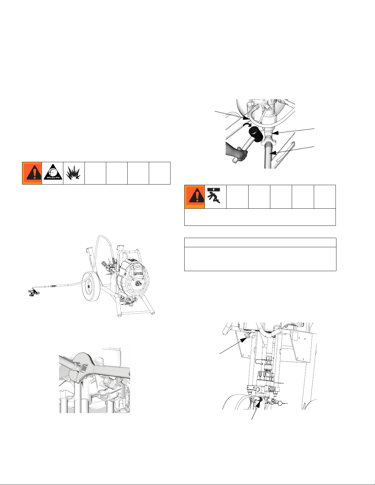
1. Flush pump; see Prime/Flush, page 14. Stop pump
at bottom of its stroke. Follow Pressure Relief Pro-
cedure, page 13.
2. Tip cart back.
4. Disconnect fluid hose (103). Disconnect suction
hose (4). Hold fluid outlet fitting (6) with a wrench to
keep it from loosening while you disconnect suction
hose.
103
6
4
TI8262a
Do not lift the pump by the lift ring when the total weight
exceeds 250 kg (550 lb).
CAUTION
Use caution when disconnecting lower; they can
weigh up to 25 kg (55 lbs). Take appropriate precautions.
3. Disconnect air hose.
r_x25dh1_x45hd1_311164_24f
TI8415a
5. Note the relative position of lower’s fluid outlet (P) to
inlet (W) of motor for easier reassembly alignment. If
motor does not require service, leave it attached to
its mounting.
W
P
TI8414a
24 311164M
Page 25
Xtreme Lower Removal
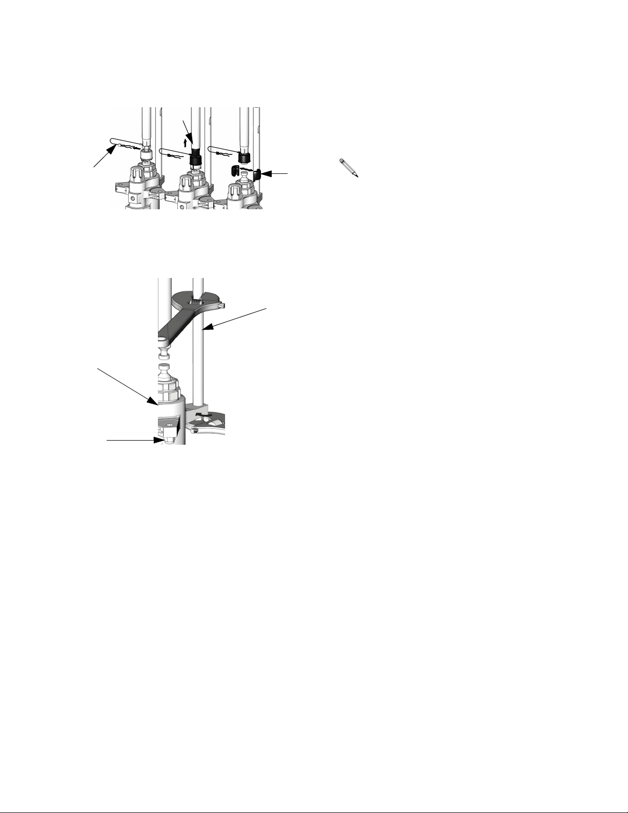
6. Remove clip (309), and slide coupling cover (307)
up to remove coupling (305).
307
309
305
TI8264a
7. Use a wrench to hold tie rod flats to keep rods (306)
from turning. Unscrew nuts (308), and remove lower
(302).
306
302
8. Refer to the Xtreme Lower manual (311762) to service lower. To service motor, refer to separate motor
manual.
9. Reconnect lower by following disconnect steps in
reverse order.
NOTE: Torque nuts (308) to 50-60 ft-lb (68-81
N•m).
308
TI8301a
311164M 25
Page 26
Wall Mount Assembly
Wall Mount Assembly
NOTE: Before mounting any pump assembly to
the wall always follow the Pressure Relief Procedure, page 13.
1. Ensure the wall is strong enough to support the
weight of the pump assembly and accessories, fluid,
hoses, and stress caused during pump operation.
2. Drill four 7/16 in. (11 mm) holes using bracket as a
template. Use any of the three mounting hole groupings in the bracket. See Pump Packages with
L290C# Lowers (16:1, 25:1, 45:1 ratio), page 50.
3. Bolt bracket securely to wall using bolts and washers designed to hold in the wall’s construction.
4. Attach pump assembly to mounting bracket (213).
5. Connect air and fluid hoses. Refer to Setup, page
12.
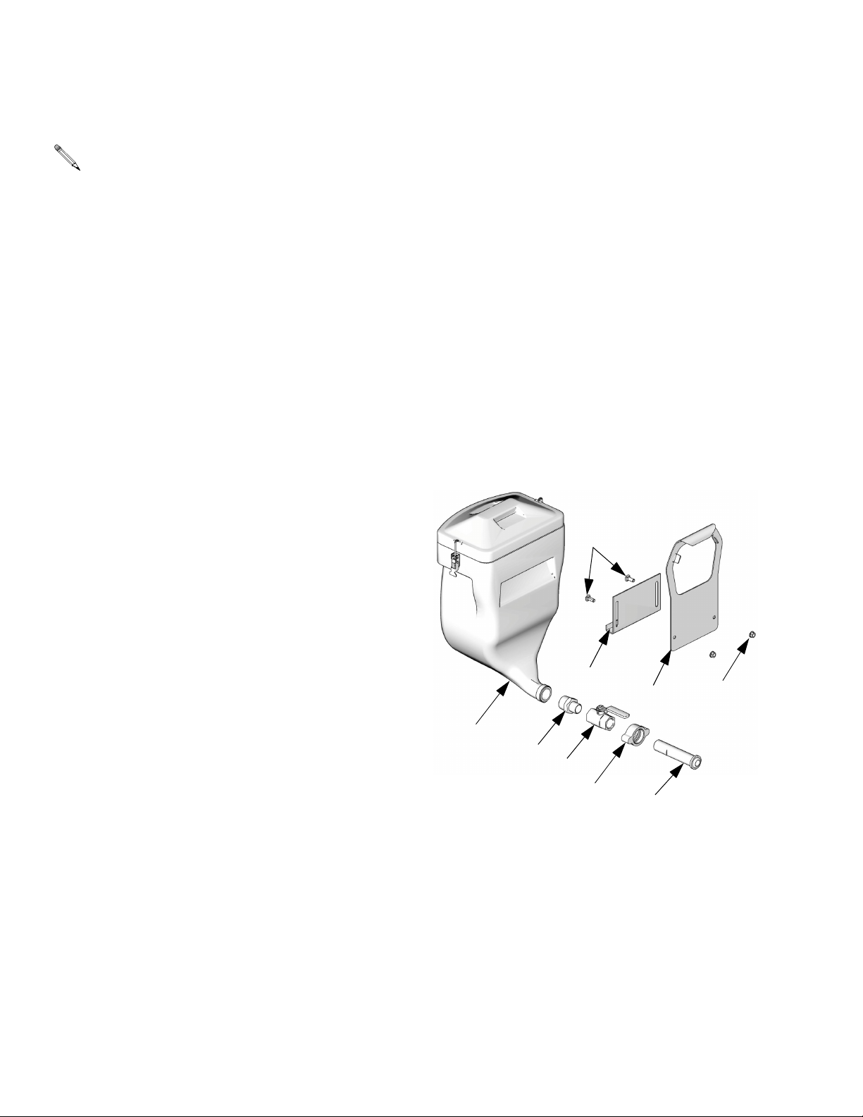
Hopper Assembly
1. Hang hopper bracket (109b) on hose rack of sprayer
cart.
2. Attach hanger bracket (109c) to hopper bracket
(109b) using supplied bolts (109f) and nuts (109g).
3. Remove fitting supplied with hopper (109a) and
replace with reducer (109n).
4. Hang hopper (109a) on bracket assembly. Adjust
bracket assembly height as necessary.
5. Assemble fittings (109d, 109m, and 109e) to hopper.
6. Attach quick disconnect fitting (109m) to fluid inlet
on pump lower.
7. Adjust bracket assembly height as necessary.
109a
109n
109d
109f
109c
109m
109b
109e
109g
TI8631a
26 311164M
Page 27

Hopper Assembly
311164M 27
Page 28
Airless Xtreme Sprayer Parts
Airless Xtreme Sprayer Parts
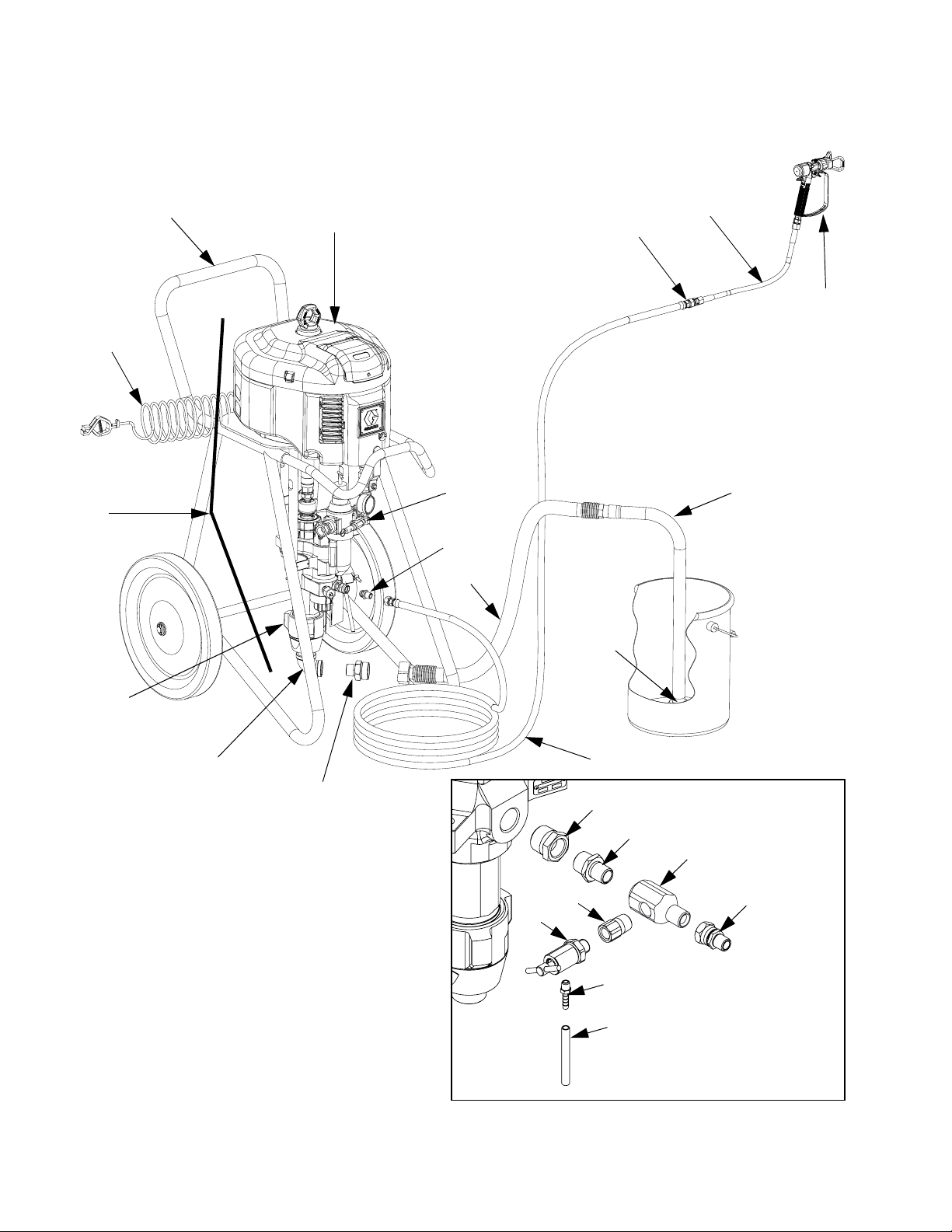
Complete Sprayer Shown (includes hose and gun)
301
2
7
303
104
14
108
4
10
102
101
3
302
5
FIG. 6: X45DL1 Model Shown
103
6
20
r_x25dh1_x45dh7
15
19
21
22
r_x25dh1_x45dl1_311164_27f
16
17
18
For pumps P45DC1,
P60DC1, and P70DC1
28 311164M
Page 29
Wall Mount Xtreme Package Parts
Wall Mount Xtreme Package Parts
203
211a
211b
301
204
303
207
213
209
302
208
205
206
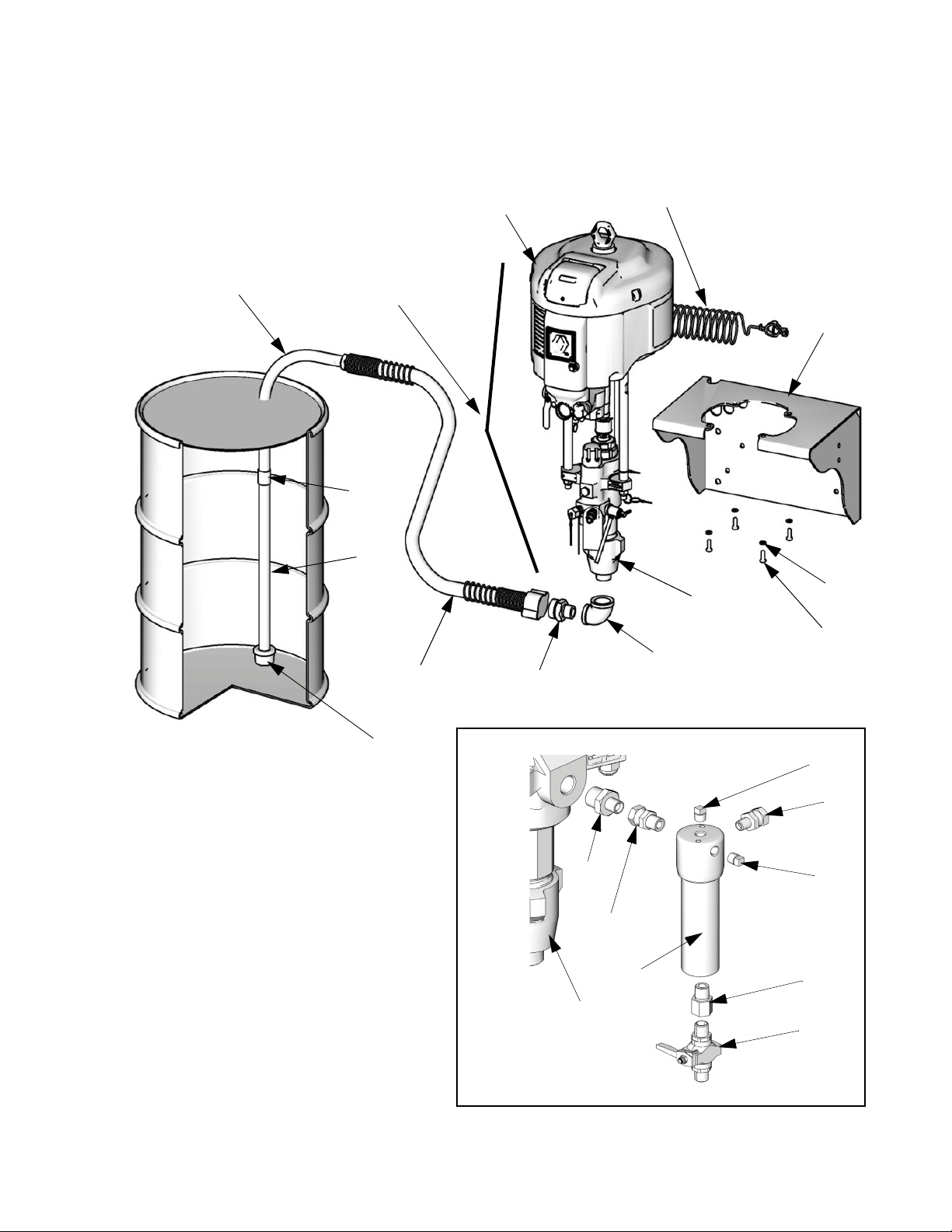
FIG. 7: Wall Mount Package
210
220
219
214
302
For pump 287978
TI8423a
215
218
215
216
217
TI8810a
311164M 29
Page 30
Parts - Airless Xtreme Sprayer Packages
Parts - Airless Xtreme Sprayer Packages
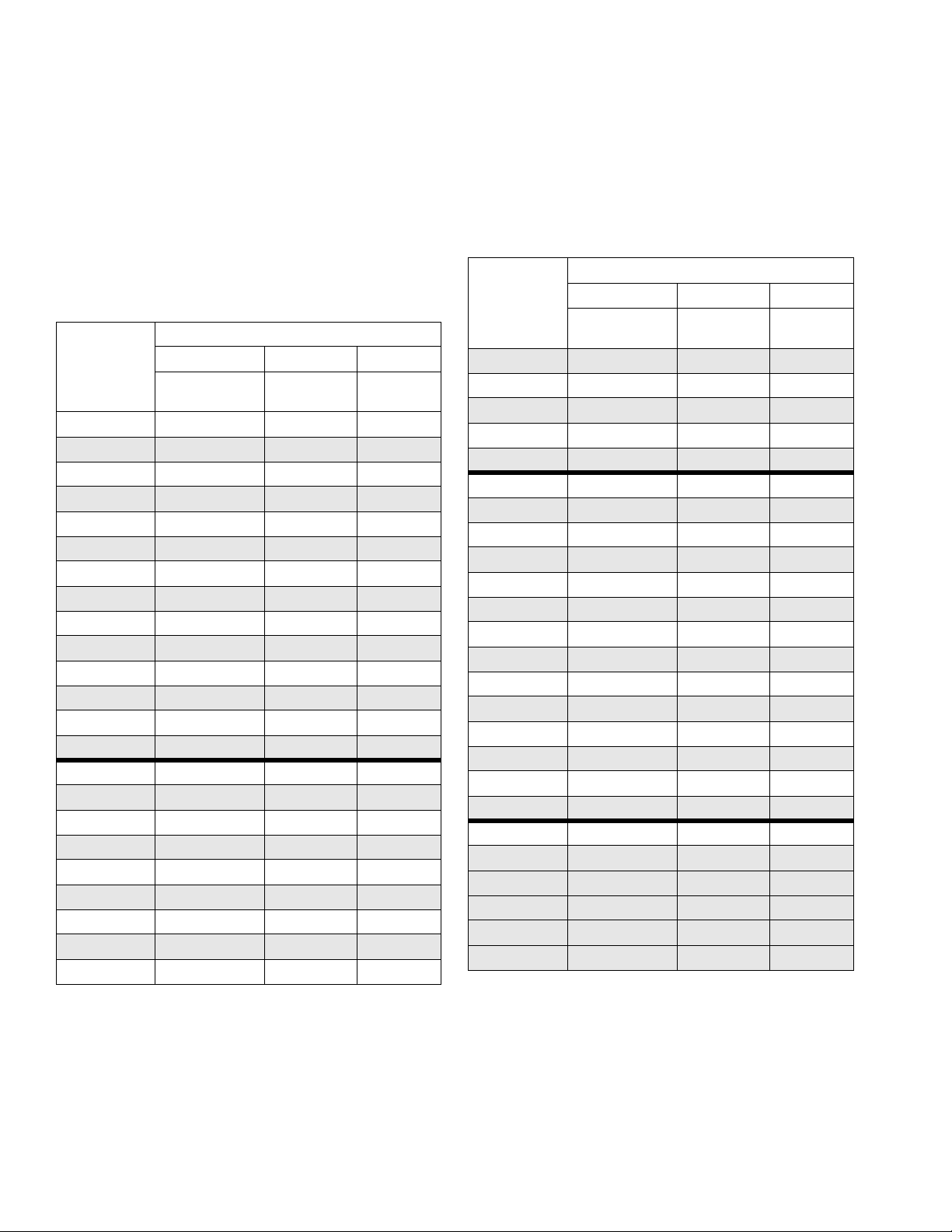
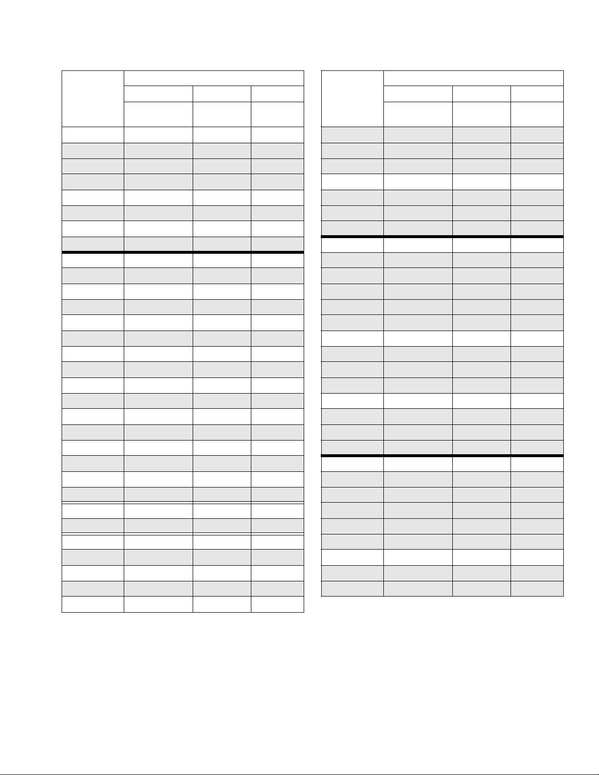
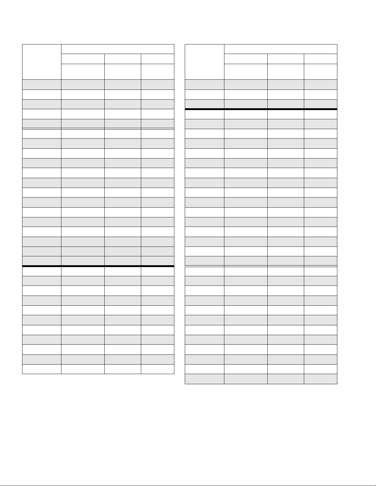
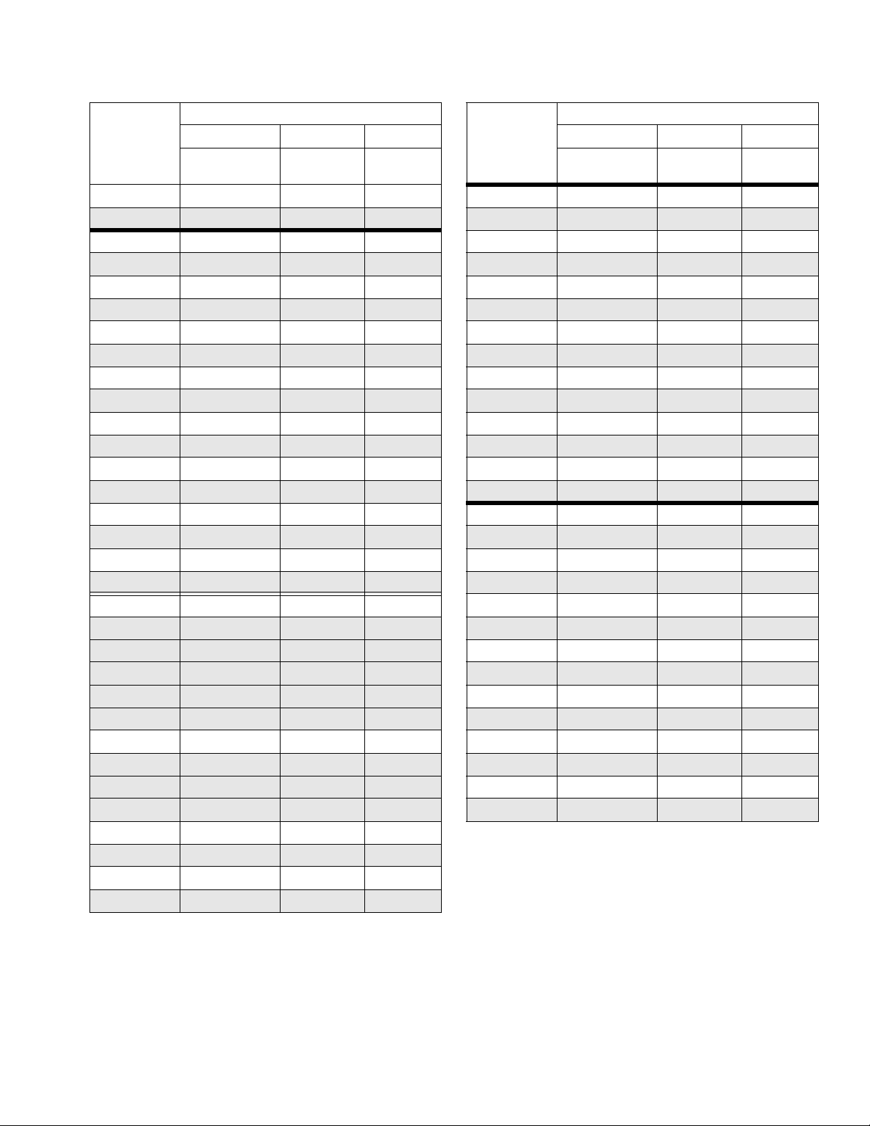
The following table lists the major components and part numbers for each airless sprayer package. Refer to Common Parts, starting on page 35, for parts included with each airless sprayer package.
To determine your specific hopper option and package part number, see the key in Hopper Options, page 34.
Component Parts - All Airless Sprayer Packages
Sprayer
Package
X25DH1 P25EC2 L290C2 N34DT0
X25DL1 P25EC2 L290C2 N34DT0
X25DH2 P25EC2 L290C2 N34DT0
X25DL2 P25EC2 L290C2 N34DT0
X25DW2 P25EC4 L290C2 N34DT0
X25DH3 P25DC2 L290C2 N34DN0
X25DL3 P25DC2 L290C2 N34DN0
X25DH4 P25DC2 L290C2 N34DN0
X25DL4 P25DC2 L290C2 N34DN0
X25DW4 P25DC4 L290C2 N34DN0
X25DH5 P25EC2 L290C2 N34DT0
X25DL5 P25EC2 L290C2 N34DT0
X25DH6 P25DC2 L290C2 N34DN0
X25DL6 P25DC2 L290C2 N34DN0
X30DH1 P30EC2 L220C2 N34DT0
X30DL1 P30EC2 L220C2 N34DT0
X30DH2 P30EC2 L220C2 N34DT0
X30DL2 P30EC2 L220C2 N34DT0
X30DW2 P30EC4 L220C2 N34DT0
X30DH3 P30DC2 L220C2 N34DN0
X30DL3 P30DC2 L220C2 N34DN0
X30DH4 P30DC2 L220C2 N34DN0
X30DL4 P30DC2 L220C2 N34DN0
Reference Number and Description
301 302 303
Pump
(see pg 43)
Lower
(see 311762)
Motor
(see 311238)
Sprayer
Package
X30DW4 P30DC4 L220C2 N34DN0
X30DH5 P30EC2 L220C2 N34DT0
X30DL5 P30EC2 L220C2 N34DT0
X30DH6 P30DC2 L220C2 N34DN0
X30DL6 P30DC2 L220C2 N34DN0
X35DH1 P35EC2 L115C2 N22DT0
X35DL1 P35EC2 L115C2 N22DT0
X35DH2 P35EC2 L115C2 N22DT0
X35DL2 P35EC2 L115C2 N22DT0
X35DW2 P35EC4 L115C2 N22DT0
X35DH3 P35DC2 L115C2 N22DN0
X35DL3 P35DC2 L115C2 N22DN0
X35DH4 P35DC2 L115C2 N22DN0
X35DL4 P35DC2 L115C2 N22DN0
X35DW4 P35DC4 L115C2 N22DN0
X35DH5 P35EC2 L115C2 N22DT0
X35DL5 P35EC2 L115C2 N22DT0
X35DH6 P35DC2 L115C2 N22DN0
X35DL6 P35DC2 L115C2 N22DN0
X40DH1 P40EC2 L180C2 N34DT0
X40DL1 P40EC2 L180C2 N34DT0
X40DH2 P40EC2 L180C2 N34DT0
X40DL2 P40EC2 L180C2 N34DT0
X40DW2 P40EC4 L180C2 N34DT0
X40DH3 P40DC2 L180C2 N34DN0
Reference Number and Description
301 302 303
Pump
(see pg 43)
Lower
(see 311762)
Motor
(see 311238)
30 311164M
Page 31
Parts - Airless Xtreme Sprayer Packages
Sprayer
Package
Reference Number and Description
301 302 303
Pump
(see pg 43)
Lower
(see 311762)
Motor
(see 311238)
X40DL3 P40DC2 L180C2 N34DN0
X40DH4 P40DC2 L180C2 N34DN0
X40DL4 P40DC2 L180C2 N34DN0
X40DW4 P40DC4 L180C2 N34DN0
X40DH5 P40EC2 L180C2 N34DT0
X40DL5 P40EC2 L180C2 N34DT0
X40DH6 P40DC2 L180C2 N34DN0
X40DL6 P40DC2 L180C2 N34DN0
X45DH1 P45EC2 L290C2 N65DT0
X45DL1 P45EC2 L290C2 N65DT0
X45DH2 P45EC2 L290C2 N65DT0
X45DL2 P45EC2 L290C2 N65DT0
X45DW2 P45EC4 L290C2 N65DT0
X45DH3 P45DC2 L290C2 N65DN0
X45DL3 P45DC2 L290C2 N65DN0
X45DH4 P45DC2 L290C2 N65DN0
X45DL4 P45DC2 L290C2 N65DN0
X45DW4 P45DC4 L290C2 N65DN0
X45DH5 P45EC2 L290C2 N65DT0
X45DL5 P45EC2 L290C2 N65DT0
X45DH6 P45DC2 L290C2 N65DN0
X45DH7 P45DC1 B290C1 N65DN0
X45DL6 P45DC2 L290C2 N65DN0
X45DL7 P45DC1 B290C1 N65DN0
X45LH1 P45MC2 L290C2 N65LT0
X45LL1 P45MC2 L290C2 N65LT0
X45LH2 P45MC2 L290C2 N65LT0
X45LL2 P45MC2 L290C2 N65LT0
X45LW2 P45MC4 L290C2 N65LT0
X45LH3 P45LC2 L290C2 N65LN0
X45LL3 P45LC2 L290C2 N65LN0
Sprayer
Package
Reference Number and Description
301 302 303
Pump
(see pg 43)
Lower
(see 311762)
Motor
(see 311238)
X45LH4 P45LC2 L290C2 N65LN0
X45LL4 P45LC2 L290C2 N65LN0
X45LW4 P45LC4 L290C2 N65LN0
X45LH5 P45MC2 L290C2 N65LT0
X45LL5 P45MC2 L290C2 N65LT0
X45LH6 P45LC2 L290C2 N65LN0
X45LL6 P45LC2 L290C2 N65LN0
X46DH1 P46EC2 L145C2 N34DT0
X46DL1 P46EC2 L145C2 N34DT0
X46DH2 P46EC2 L145C2 N34DT0
X46DL2 P46EC2 L145C2 N34DT0
X46DW2 P46EC4 L145C2 N34DT0
X46DH3 P46DC2 L145C2 N34DN0
X46DL3 P46DC2 L145C2 N34DN0
X46DH4 P46DC2 L145C2 N34DN0
X46DL4 P46DC2 L145C2 N34DN0
X46DW4 P46DC4 L145C2 N34DN0
X46DH5 P46EC2 L145C2 N34DT0
X46DL5 P46EC2 L145C2 N34DT0
X46DH6 P46DC2 L145C2 N34DN0
X46DL6 P46DC2 L145C2 N34DN0
X50DH1 P50EC2 L250C2 N65DT0
X50DL1 P50EC2 L250C2 N65DT0
X50DH2 P50EC2 L250C2 N65DT0
X50DL2 P50EC2 L250C2 N65DT0
X50DW2 P50EC4 L250C2 N65DT0
X50DH3 P50DC2 L250C2 N65DN0
X50DL3 P50DC2 L250C2 N65DN0
X50DH4 P50DC2 L250C2 N65DN0
X50DL4 P50DC2 L250C2 N65DN0
311164M 31
Page 32
Parts - Airless Xtreme Sprayer Packages
Sprayer
Package
Reference Number and Description
301 302 303
Pump
(see pg 43)
Lower
(see 311762)
Motor
(see 311238)
X50DW4 P50DC4 L250C2 N65DN0
X50DH5 P50EC2 L250C2 N65DT0
X50DL5 P50EC2 L250C2 N65DT0
X50DH6 P50DC2 L250C2 N65DN0
X50DL6 P50DC2 L250C2 N65DN0
X50LH1 P50MC2 L250C2 N65LT0
X50LL1 P50MC2 L250C2 N65LT0
X50LH2 P50MC2 L250C2 N65LT0
X50LL2 P50MC2 L250C2 N65LT0
X50LW2 P50MC4 L250C2 N65LT0
X50LH3 P50LC2 L250C2 N65LN0
X50LL3 P50LC2 L250C2 N65LN0
X50LH4 P50LC2 L250C2 N65LN0
X50LL4 P50LC2 L250C2 N65LN0
X50LW4 P50LC4 L250C2 N65LN0
X50LH5 P50MC2 L250C2 N65LT0
X50LL5 P50MC2 L250C2 N65LT0
X50LH6 P50LC2 L250C2 N65LN0
X50LL6 P50LC2 L250C2 N65LN0
X55DH1 P55EC2 L115C2 N34DT0
X55DL1 P55EC2 L115C2 N34DT0
X55DH2 P55EC2 L115C2 N34DT0
X55DL2 P55EC2 L115C2 N34DT0
X55DW2 P55EC4 L115C2 N34DT0
X55DH3 P55DC2 L115C2 N34DN0
X55DL3 P55DC2 L115C2 N34DN0
X55DH4 P55DC2 L115C2 N34DN0
X55DL4 P55DC2 L115C2 N34DN0
X55DW4 P55DC4 L115C2 N34DN0
X55DH5 P55EC2 L115C2 N34DT0
Sprayer
Package
Reference Number and Description
301 302 303
Pump
(see pg 43)
Lower
(see 311762)
Motor
(see 311238)
X55DL5 P55EC2 L115C2 N34DT0
X55DH6 P55DC2 L115C2 N34DN0
X55DL6 P55DC2 L115C2 N34DN0
X60DH1 P60EC2 L220C2 N65DT0
X60DL1 P60EC2 L220C2 N65DT0
X60DH2 P60EC2 L220C2 N65DT0
X60DL2 P60EC2 L220C2 N65DT0
X60DW2 P60EC4 L220C2 N65DT0
X60DH3 P60DC2 L220C2 N65DN0
X60DL3 P60DC2 L220C2 N65DN0
X60DH4 P60DC2 L220C2 N65DN0
X60DL4 P60DC2 L220C2 N65DN0
X60DW4 P60DC4 L220C2 N65DN0
X60DH5 P60EC2 L220C2 N65DT0
X60DL5 P60EC2 L220C2 N65DT0
X60DH6 P60DC2 L220C2 N65DN0
X60DH7 P60DC1 B220C1 N65DN0
X60DL6 P60DC2 L220C2 N65DN0
X60DL7 P60DC1 B220C1 N65DN0
X60LH1 P60MC2 L220C2 N65LT0
X60LL1 P60MC2 L220C2 N65LT0
X60LH2 P60MC2 L220C2 N65LT0
X60LL2 P60MC2 L220C2 N65LT0
X60LW2 P60MC4 L220C2 N65LT0
X60LH3 P60LC2 L220C2 N65LN0
X60LL3 P60LC2 L220C2 N65LN0
X60LH4 P60LC2 L220C2 N65LN0
X60LL4 P60LC2 L220C2 N65LN0
X60LW4 P60LC4 L220C2 N65LN0
X60LH5 P60MC2 L220C2 N65LT0
X60LL5 P60MC2 L220C2 N65LT0
32 311164M
Page 33
Parts - Airless Xtreme Sprayer Packages
Sprayer
Package
Reference Number and Description
301 302 303
Pump
(see pg 43)
Lower
(see 311762)
Motor
(see 311238)
X60LH6 P60LC2 L220C2 N65LN0
X60LL6 P60LC2 L220C2 N65LN0
X70DH1 P70EC2 L180C2 N65DT0
X70DL1 P70EC2 L180C2 N65DT0
X70DH2 P70EC2 L180C2 N65DT0
X70DL2 P70EC2 L180C2 N65DT0
X70DW2 P70EC4 L180C2 N65DT0
X70DH3 P70DC2 L180C2 N65DN0
X70DL3 P70DC2 L180C2 N65DN0
X70DH4 P70DC2 L180C2 N65DN0
X70DL4 P70DC2 L180C2 N65DN0
X70DW4 P70DC4 L180C2 N65DN0
X70DH5 P70EC2 L180C2 N65DT0
X70DL5 P70EC2 L180C2 N65DT0
X70DH6 P70DC2 L180C2 N65DN0
X70DH7 P70DC1 B180C1 N65DN0
X70DL6 P70DC2 L180C2 N65DN0
X70DL7 P70DC1 B180C1 N65DN0
X70LH1 P70MC2 L180C2 N65LT0
X70LL1 P70MC2 L180C2 N65LT0
X70LH2 P70MC2 L180C2 N65LT0
X70LL2 P70MC2 L180C2 N65LT0
X70LW2 P70MC4 L180C2 N65LT0
X70LH3 P70LC2 L180C2 N65LN0
X70LL3 P70LC2 L180C2 N65LN0
X70LH4 P70LC2 L180C2 N65LN0
X70LL4 P70LC2 L180C2 N65LN0
X70LW4 P70LC4 L180C2 N65LN0
X70LH5 P70MC2 L180C2 N65LT0
X70LL5 P70MC2 L180C2 N65LT0
X70LH6 P70LC2 L180C2 N65LN0
X70LL6 P70LC2 L180C2 N65LN0
Sprayer
Package
Reference Number and Description
301 302 303
Pump
(see pg 43)
Lower
(see 311762)
Motor
(see 311238)
X80DH1 P80EC2 L085C2 N34DT0
X80DL1 P80EC2 L085C2 N34DT0
X80DH2 P80EC2 L085C2 N34DT0
X80DL2 P80EC2 L085C2 N34DT0
X80DW2 P80EC4 L085C2 N34DT0
X80DH3 P80DC2 L085C2 N34DN0
X80DL3 P80DC2 L085C2 N34DN0
X80DH4 P80DC2 L085C2 N34DN0
X80DL4 P80DC2 L085C2 N34DN0
X80DW4 P80DC4 L085C2 N34DN0
X80DH5 P80EC2 L085C2 N34DT0
X80DL5 P80EC2 L085C2 N34DT0
X80DH6 P80DC2 L085C2 N34DN0
X80DL6 P80DC2 L085C2 N34DN0
X90DH1 P90EC2 L145C2 N65DT0
X90DL1 P90EC2 L145C2 N65DT0
X90DH2 P90EC2 L145C2 N65DT0
X90DL2 P90EC2 L145C2 N65DT0
X90DW2 P90EC4 L145C2 N65DT0
X90DH3 P90DC2 L145C2 N65DN0
X90DL3 P90DC2 L145C2 N65DN0
X90DH4 P90DC2 L145C2 N65DN0
X90DL4 P90DC2 L145C2 N65DN0
X90DW4 P90DC4 L145C2 N65DN0
X90DH5 P90EC2 L145C2 N65DT0
X90DL5 P90EC2 L145C2 N65DT0
X90DH6 P90DC2 L145C2 N65DN0
X90DL6 P90DC2 L145C2 N65DN0
311164M 33
Page 34

Parts - Airless Xtreme Sprayer Packages
Sprayer
Package
Reference Number and Description
301 302 303
Pump
(see pg 43)
Lower
(see 311762)
Motor
(see 311238)
X90LH1 P90MC2 L145C2 N65LT0
X90LL1 P90MC2 L145C2 N65LT0
X90LH2 P90MC2 L145C2 N65LT0
X90LL2 P90MC2 L145C2 N65LT0
X90LW2 P90MC4 L145C2 N65LT0
X90LH3 P90LC2 L145C2 N65LN0
X90LL3 P90LC2 L145C2 N65LN0
X90LH4 P90LC2 L145C2 N65LN0
X90LL4 P90LC2 L145C2 N65LN0
X90LW4 P90LC4 L145C2 N65LN0
X90LH5 P90MC2 L145C2 N65LT0
X90LL5 P90MC2 L145C2 N65LT0
X90LH6 P90LC2 L145C2 N65LN0
X90LL6 P90LC2 L145C2 N65LN0
Hopper Options
If your sprayer package includes a hopper, use the following table to determine the specific hopper option. For
example, X60DH5 indicates the airless sprayer package
includes a hopper, gun, hose, and DataTrak.
Digit 6 Option
5 Hopper Package; complete package
with DataTrak
6 Hopper Package; complete package
without DataTrak
7 Lower without integrated fluid filter
Motor Key
First Digit
Second and
Third Digits
Fourth Digit
Fifth Digit
Sixth Digit
Motor N (NXT Air Motor)
cc per stroke 65 = 6500
34 = 3400
22 = 2200
Exhaust Type D = De-icing
L = Low noise
R = Remote
Data
Monitoring
Unassigned 0 = Non assigned
N = None
T = DataTrak
H = High level linear sensor
34 311164M
Page 35

Common Parts
Parts - Airless Xtreme Sprayer Packages
Airless Sprayer Packages
The following parts are included with each airless
sprayer package:
Ref. Part Description Qty.
2CART 1
287884 Heavy duty (H); see pg. 39
287919 Light weight (L); see pg. 39
3 197682 TUBE, suction 1
4 247301 HOSE, suction, 1 in., NPT x quick
connect, 6 ft.
5 116401 ADAPTER, elbow 1
6 116402 ADAPTER, quick connect 1
7 244524 WIRE, ground assy. w/ clamp 1
10 181072 INLET, strainer 1
11❄ 100101 SCREW, mounting, cap, hex head 4
12❄ 100133 WASHER, lock 4
13◆ 247312 PLATE, adapter kit (includes
13a-13b) for NXT 2200 Air Motors
13a❄ NUT, lock 4
13b❄ PLATE, adapter 1
14 AIR CONTROLS 1
24E013 CONTROL, air, heavy duty cart;
see manual 3A0293
24E025 CONTROL, air, light duty cart;
see manual 3A0293
15† 158586 FITTING, bushing 1
16 157191 FITTING, adapter 1
17 15R873 FITTING, tee, 1/2 1
18 162505 FITTING, union, swivel 1
19 121433 FITTING, bushing, 1/2x3/8 1
20 245143 VALVE, pressure, bleed 1
21 116746 FITTING, barbed 1
22 116750 TUBE, nylon 1
The following parts are included with only complete airless sprayer packages:
Ref. Part Description Qty.
101 GUN, spray 1
XTR504 XTR5 spray gun for models with
XTR704 XTR7 spray gun for models with
1
102 HOSE, fluid; nylon; 1/4 in. ID, 1/4
H42506 Models with 25:1 - 45:1 ratio
H52506 Models with 46:1 - 55:1 ratio
H72506 Models with 60:1 - 90:1 ratio
103 HOSE, fluid; nylon, 3/8 in. ID; 3/8
1
H43850 Models with 25:1 - 45:1 ratio
H53850 Models with 46:1 - 55:1 ratio
H73850 Models with 60:1 - 90:1 ratio
104 164856 FITTING, nipple, reducing;
108 162505 FITTING, union, swivel;
25:1 - 50:1 ratio only
55:1 - 90:1 ratio only
1
npsm(fbe); 6 ft.
1
npsm(fbe); 50 ft.
1
3/8 x 1/4 npt(m)
1
1/2 in. F x 3/8 in. M
◆ X35*** models only.
† X45D*7 and X60D*7 models only.
❄ Not shown.
311164M 35
Page 36

Parts - Airless Xtreme Sprayer Packages
Airless Sprayers with Hopper Packages
Hopper kit is shown on page 26.
Ref. Part Description Qty.
2CART 1
287884 Heavy duty (H); see pg. 39
287919 Light weight (L); see pg. 39
5 116401 ADAPTER, elbow 1
6 116402 ADAPTER, quick connect 1
7 244524 WIRE, ground assy. w/ clamp 1
11❄ 100101 SCREW, mounting, cap, hex head 4
12❄ 100133 WASHER, lock 4
14 AIR CONTROLS 1
24E013 CONTROL, air, heavy duty cart;
see manual 3A0293
24E025 CONTROL, air, light duty cart;
see manual 3A0293
101 GUN, spray 1
XTR504 XTR5 spray gun for models with
25:1 - 50:1 ratio only
XTR704 XTR7 spray gun for models with
55:1 - 90:1 ratio only
102 HOSE, fluid; nylon; 1/4 in. ID, 1/4
npsm(fbe); 6 ft.
H42506 Models with 25:1 - 45:1 ratio
H52506 Models with 46:1 - 55:1 ratio
H72506 Models with 60:1 - 90:1 ratio
103 HOSE, fluid; nylon, 3/8 in. ID; 3/8
npsm(fbe); 50 ft.
H43850 Models with 25:1 - 45:1 ratio
H53850 Models with 46:1 - 55:1 ratio
H73850 Models with 60:1 - 90:1 ratio
104 164856 FITTING, NIPPLE, reducing;
3/8 x 1/4 npt(m)
108 162505 FITTING, union, swivel;
1/2 in. F x 3/8 in. M
109 288347 HOPPER, kit (includes a - n) 1
109a HOPPER, fluid 1
109b BRACKET, hopper 1
109c BRACKET, hanger, hopper 1
109d VALVE, ball 1
109e FITTING, connection, hopper 1
109f SCREW, cap, hex head 2
109g NUT, hex, flanged 2
109m NUT, wing 1
109n FITTING, NIPPLE, reducing 1
110◆ 247312 PLATE, adapter kit (includes a-b)
for NXT 2200 Air Motors
110a❄ NUT, lock 4
110b❄ PLATE, adapter 1
◆ X35*** models only.
❄ Not shown.
Wall Mount Packages
Ref. Part Description Qty.
203 197682 TUBE, suction 1
204 247302 HOSE, suction,1 in.,
205 116401 ADAPTER, elbow 1
206 116402 ADAPTER, quick connect 1
207 244524 WIRE, ground assy. w/clamp 1
208 100101 SCREW, mounting, cap, hex head 4
209 100133 WASHER, lock 4
210 181072 INLET, strainer 1
211 245136 TUBE, intake extension
211a COUPLING, pipe, 1 in. 1
211b TUBE, intake 1
213 255143 BRACKET (W), mounting
214◆ 247312 PLATE, adapter kit (includes
214a❄ NUT, lock 4
214b❄ PLATE, adapter 1
1
◆ X35*** models only.
❄ Not shown.
1
Wall Mount Package 287978
Ref. Part Description Qty.
203 197682 TUBE, suction 1
204 247302 HOSE, suction,1 in.,
1
205 116401 ADAPTER, elbow 1
206 116402 ADAPTER, quick connect 1
1
207 244524 WIRE, ground assy. w/clamp 1
208 100101 SCREW, mounting, cap, hex head 4
209 100133 WASHER, lock 4
210 181072 INLET, strainer 1
211 245136 TUBE, intake extension
211a COUPLING, pipe, 1 in. 1
211b TUBE, intake 1
213 255143 BRACKET (W), mounting
214 218029 FILTER, fluid 1
1
215 100509 PLUG, pipe 2
216 150286 ADAPTER, 2 x 3/8-18 NPT 1
217 210658 VALVE, ball 1
218 157705 UNION, swivel, 3/8-18 npsm x
219 155665 UNION, adapter, 3/8-18 npsm x
220 161800 ADAPTER, 3/4 x 3/8 mbe 1
301 P40MC3 PUMP 1
1
NPT x quick connect; 10 ft.
1
(includes 211a-211b)
1
(includes 208-209)
1
214a-214b) for NXT 2200 Air
Motors
1
NPT x quick connect; 10 ft.
1
(includes 211a-211b)
1
(includes 208-209)
1
1/4-18 NPT
1
3/8-18 NPT
NOTE: Wall Mount Package parts are shown on
page 29.
36 311164M
Page 37
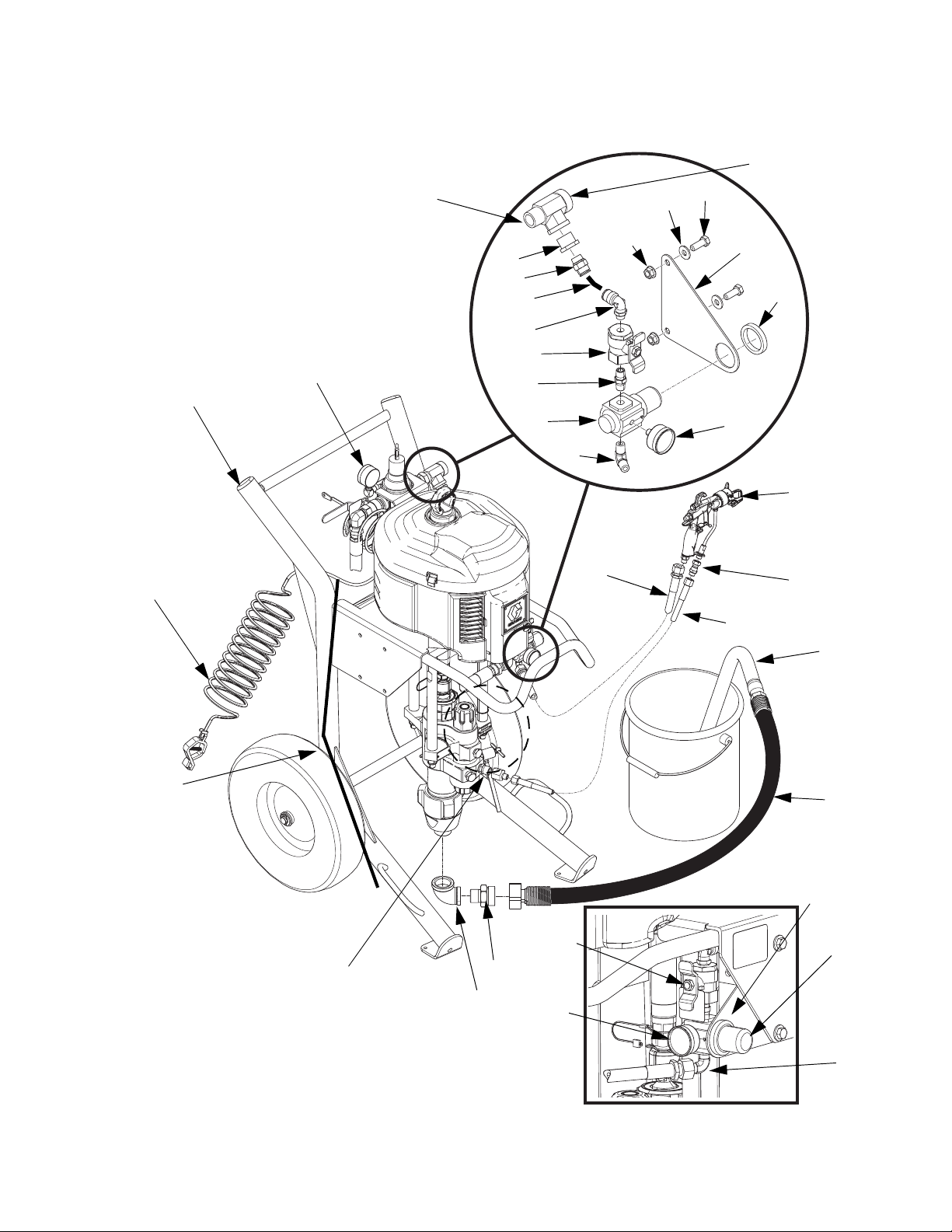
Air-Assisted Xtreme Sprayer Parts
To air control
Air-Assisted Xtreme Sprayer Parts
438*
(To air inlet)
436*
416*
407
402
444
440*
439*
441*
431*
428*
430*
415*
435*
429
437*
410*
417*
427*
419
434
433
403
401
404
WLD
428*
443
Side View - Air Regulator Mounting Kit 288527
FIG. 8: Model 287976
311164M 37
406
405
427*
410*
415*
435*
Page 38
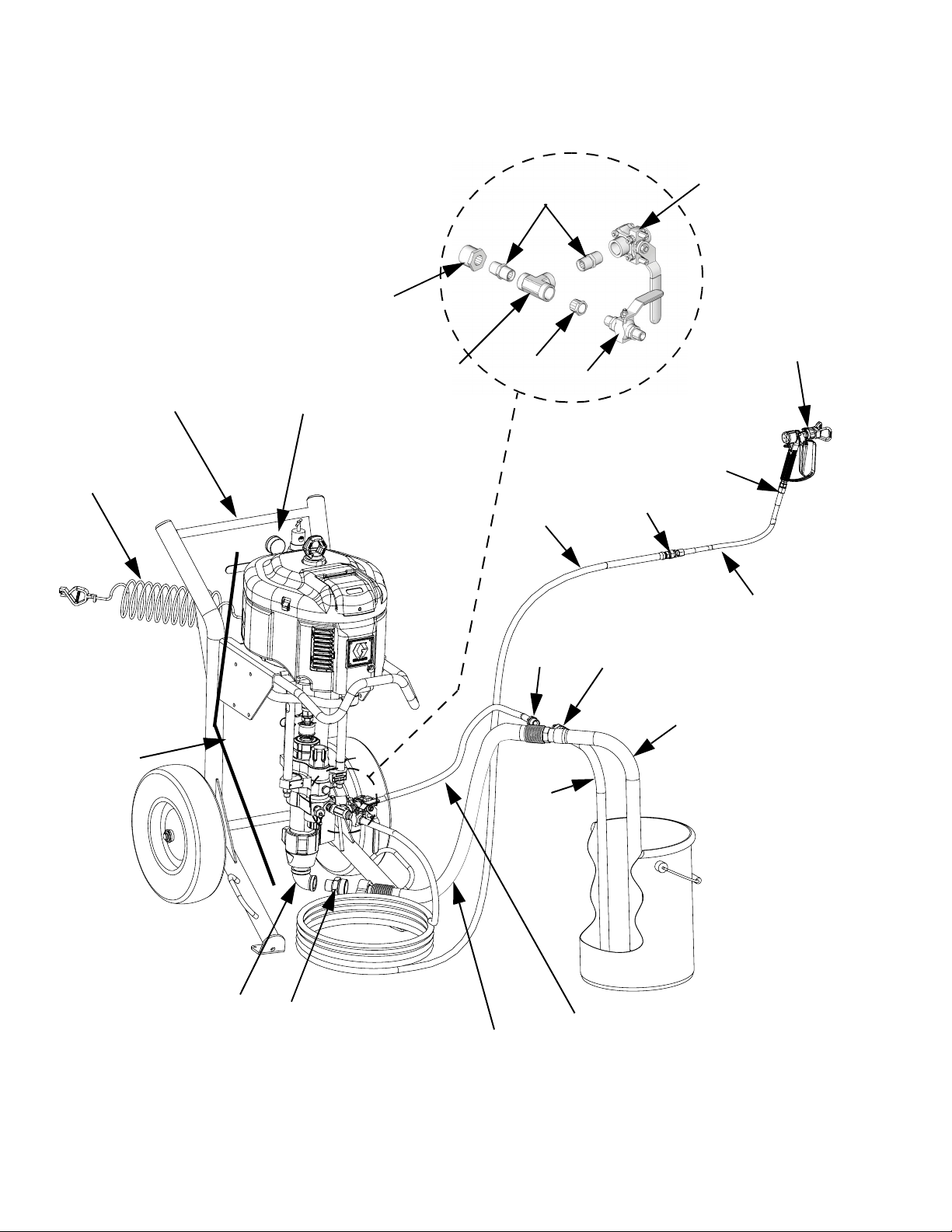
Zinc Xtreme Sprayer Parts
Zinc Xtreme Sprayer Parts
532
542
533†
507
501
502
544
531
530
538
537
535
529
519
TI8754a
541
543
540
536
503
505
FIG. 9: Model 287973 Shown
38 311164M
506
(Fluid Return Line)
534
504
r_x25dh1_x45dh1_311164_34
Page 39

Parts - Air-Assisted and Zinc Sprayer Packages
Parts - Air-Assisted and Zinc Sprayer Packages
Air-Assisted Sprayer Packages
Models 287975 and 287976
Ref. Part Description Qty.
401 P30DC2 PUMP, assy. 287975 1
P40DC2 PUMP, assy. 287976 1
402 287884 CART, heavy duty; see pg. 39 1
403 197682 TUBE, suction 1
404 247301 HOSE, suction, 1 in.,
NPT x quick connect, 6 ft.
405 116401 ADAPTER, elbow 1
406 116402 ADAPTER, quick connect 1
407 244524 WIRE, ground assembly w/ clamp 1
410* 288523 BRACKET, air controls 1
415* 116513 REGULATOR, air, gun 1
416* 100101 SCREW, mounting, cap, hex hd 6
417* 116514 NUT, regulator mount 1
418❄ 100133 WASHER, lock 4
419 24C857 GUN, spray 1
427* 108190 GAUGE, pressure, gun 1
428* 116473 VALVE, ball, vented, 2 way 1
429 210868 HOSE, air, coupled, 50 ft. 1
430* 156971 NIPPLE, short 1
431* 114128 ELBOW, male, swivel 1
433 H52550 HOSE, fluid; nylon, 1/4 in. ID; 1/4
npsm(fbe); 50 ft.
434 189018 SWIVEL 1
435* 111763 ELBOW, 1/4 npt 1
436* 100023 WASHER, flat 2
437* 112958 NUT, hex, flanged 2
438* 111337 FITTING, tee, street 1
439* 114129 CONNECTOR, male 1
440* 100505 BUSHING, pipe 1
441* TUBE 1
443 159842 ADAPTER, bushing, 1/4 npt(m) x
1/2 npt(f)
444 24E013 CONTROLS, air, heavy duty cart 1
Zinc Sprayer Packages
Models 287971, 287972, 287973, 287974
Ref. Part Description Qty.
501 P25DC1 PUMP, assy. 287971 and 287973 1
P40DC1 PUMP, assy. 287972 and 287974 1
502 287884 CART, heavy duty; see pg. 39 1
503 197682 TUBE, suction 1
504 247301 HOSE, suction, 1 in.,
1
NPT x quick connect, 6 ft.
505 116401 ADAPTER, elbow 1
506 116402 ADAPTER, quick connect 1
507 244524 WIRE, ground assembly w/ clamp 1
516❄ 100101 SCREW, mounting, cap, hex hd 4
518❄ 100133 WASHER, lock 4
519✓ 238591 GUN, spray 1
529 238612 VALVE, ball 1
530 100081 BUSHING, pipe 1
531 103475 FITTING, tee, pipe 1
532 BUSHING, pipe
100380 Model 287973 1
157191 Model 287974 1
533† 158491 FITTING, nipple
534 235148 HOSE, coupled, 6 ft 1
535 100896 FITTING, bushing, pipe 1
1
536 157785 FITTING, swivel 1
537 165767 TUBE, suction 1
538✓ H43850 HOSE, fluid; nylon, 3/8 in. ID; 3/8
npsm(fbe); 50 ft.
540✓ H42506 HOSE, fluid; nylon; 1/4 in. ID, 1/4
npsm(fbe); 6 ft.
541✓ 189018 FITTING, swivel, 1/4-18 npsm(f) x
1/4-18 npsm(m)
542 102646 VALVE, ball 1
1
543✓ 164856 FITTING, nipple, reducing;
3/8 x 1/4 npt(m)
544 24E013 CONTROLS, air, heavy duty cart 1
1
1
1
1
1
❄ Not shown.
* Included in Air Regulator Mounting Kit 288527.
311164M 39
❄ Not shown.
† Quantity of two for Models 287971 and 287973;
quantity of one for Models 287972 and 287974.
✓ Models 287973 and 287974 only.
Page 40
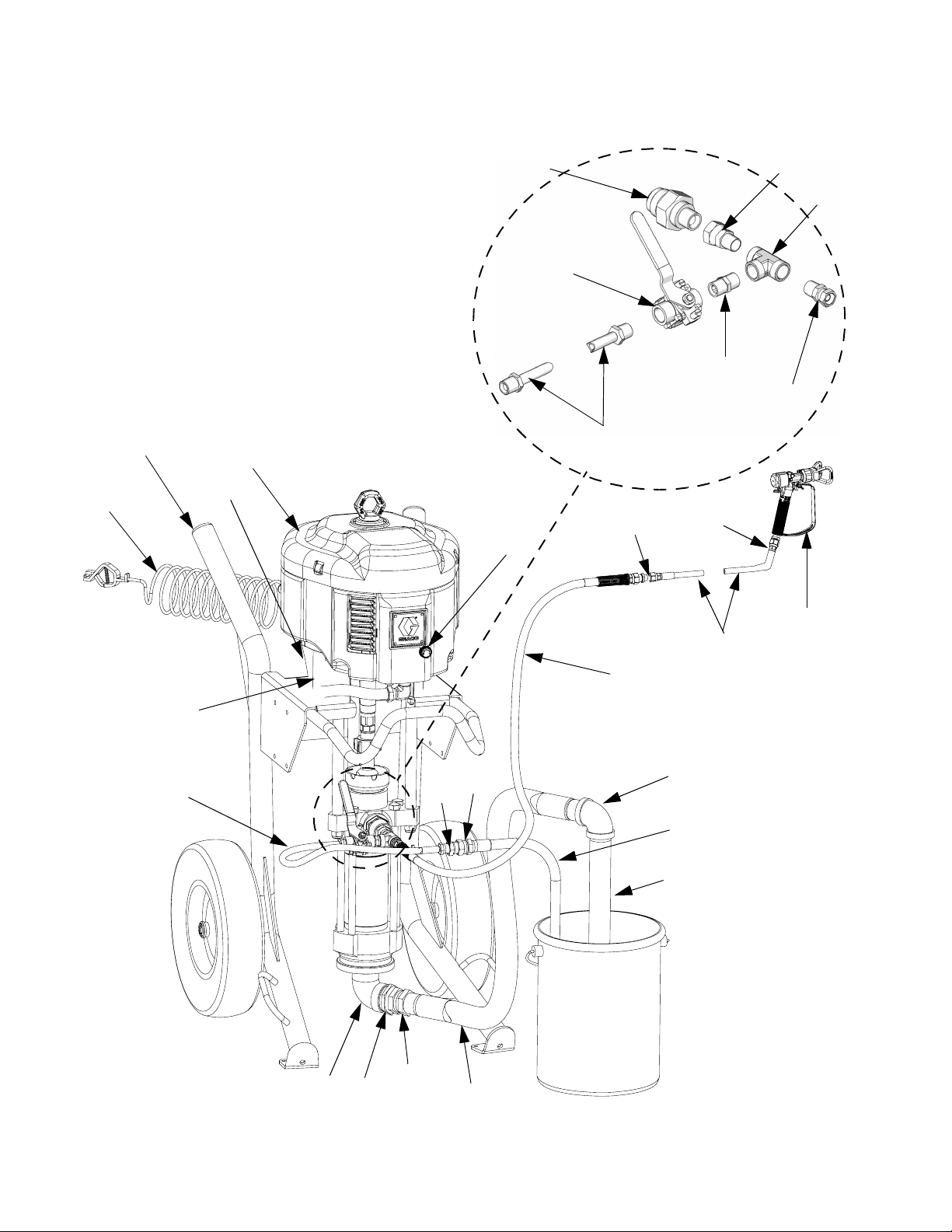
Dura-Flo Sprayer Parts
Dura-Flo Sprayer Parts
616
602
603
601
617, 618
645
630†
631†
634†
641
629†
642†
632†
TI9162a
636†
604, 605
631†
638†
639†
637†
635†
633†
614
640†
615
611610
FIG. 10: Model 287980
40 311164M
612
613
r_287979_311164_36f
Page 41

Parts - Dura-Flo Sprayer Packages
Parts - Dura-Flo Sprayer Packages
Model 287979, 287980, and 287981
NOTE: Model 287980 is the only model that
includes a gun and hose.
Ref. Part Description Qty.
601 P23DCD PUMP, Dura-Flo,6500/580 1
★P32DCD PUMP, Dura-Flo, 6500/430 1
602 287884 CART, heavy duty, see pg. 42 1
603 24E013 CONTROL, air, heavy duty cart;
see manual 3A0293
604 15K296 SPACER 1
605❄ 120465 SPACER, mounting, threaded 4
606❄ 100133 WASHER, lock 4
610 100088 ELBOW, street, pipe, 90 degrees 1
611 109505 BUSHING 1
612 113864 UNION, swivel,1 1/2 npt 1
613 222914 HOSE, coupled 1
614 109475 ELBOW, pipe, female, 90 degrees 1
615 184475 TUBE, suction 1
616 244524 WIRE, ground assembly w/ clamp 1
617 109213 PACKING, o-ring 1
618 184470 FITTING, outlet 1
Ref. Part Description Qty.
629† 103475 FITTING, tee, pipe 1
630† 102646 VALVE, ball 1
631† 235148 HOSE, coupled, 6 ft 1
632† 158256 UNION, swivel 1
633† 240797 HOSE, coupled, 3/8 x 50 1
634† 164856 FITTING, nipple, reducing 1
635† 239984 HOSE, coupled, 1/4 in. x 25 1
636† 189018 SWIVEL, 5800 psi 1
637† 238591 GUN, spray 1
638† 100896 FITTING, bushing, pipe 1
1
639† 157785 FITTING, swivel 1
640† 165767 TUBE, suction 1
641† 113344 SWIVEL, union assy 1
642† 158491 FITTING, nipple 1
644❄ 100131 NUT, full hex 4
645 15J277 CONTROL, de-ice, assembly 1
† Model 287980 only.
★ Model 287981 only.
❄ Not shown.
311164M 41
Page 42
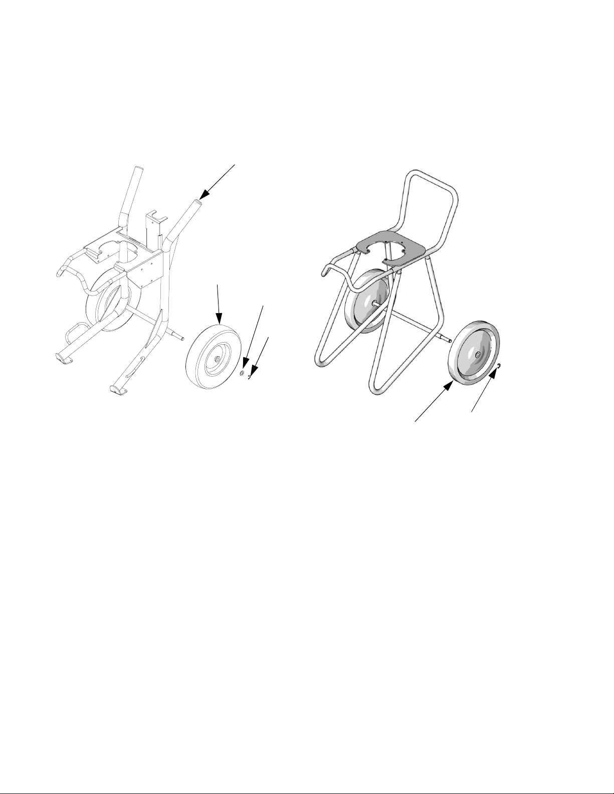
Cart Parts
Cart Parts
Heavy Duty Cart, Model 287884 Light Weight Cart, Model 287919
2
3
4
5
r_x25dh1_x45dh1_311164_38f
Ref. Part Description Qty.
2 113361 CAP, tube, round 2
3 113362 WHEEL, semi-pneumatic 2
4WASHER 2
5 113436 RING, retaining 2
Ref. Part Description Qty.
2 116406 WHEEL, semi-pneumatic 2
3 113436 RING, retaining 2
2
3
TI8409a
42 311164M
Page 43
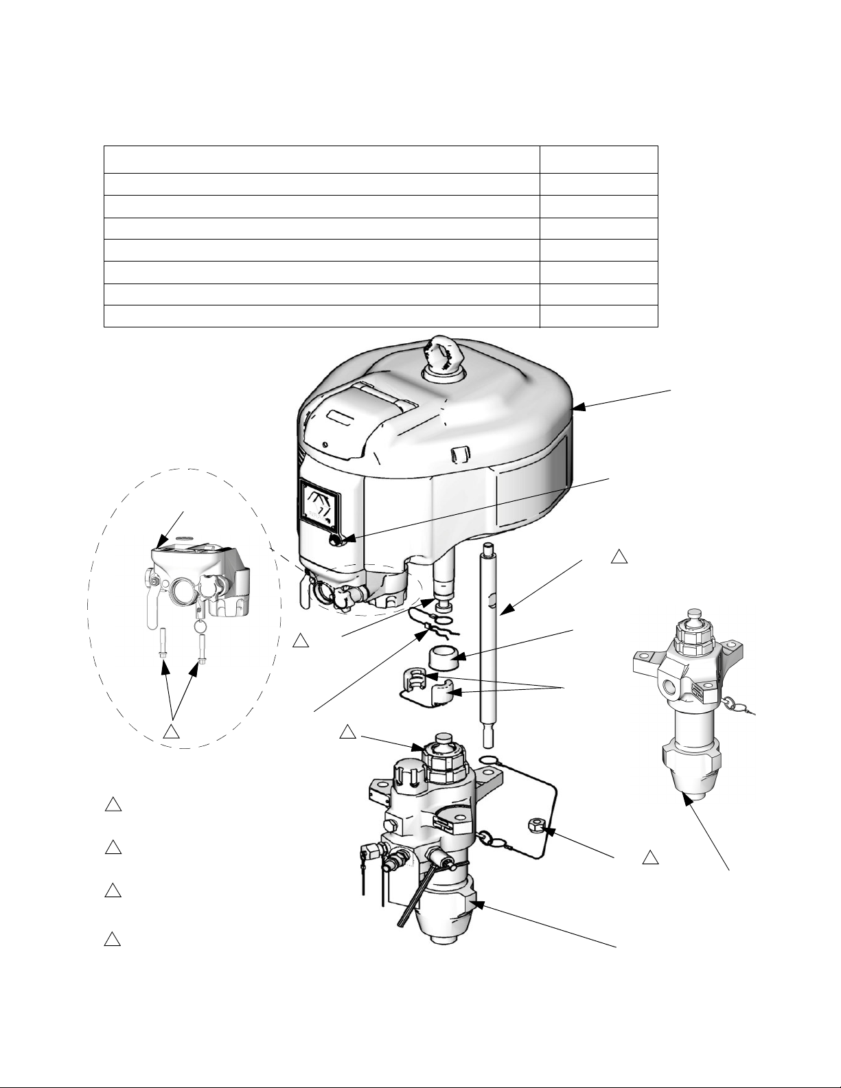
Pump Package Parts
Pump Package Parts List Page
Pump Package Parts
Pump Packages with L085C# Lowers (80:1 ratio)
Pump Packages with L115C# Lowers (35:1, 55:1 ratio)
Pump Packages with L145C# and L14AC1 Lowers (31:1, 46:1, 90:1 ratio)
Pump Packages with L180C# and L18AC1 Lowers (24:1, 40:1, 70:1 ratio)
Pump Packages with L220C# Lowers (21:1, 30:1, 60:1 ratio)
Pump Packages with L250C# Lowers (50:1 ratio)
Pump Packages with L290C# Lowers (16:1, 25:1, 45:1 ratio)
304 (NXT021)
pg 44
pg 45
pg 46
pg 47
pg 48
pg 49
pg 50
306
303
311
2
4
Torque to 25-30 ft-lb
1
(34-41 N•m)
Torque to 50-60 ft-lb
2
(68-81 N•m)
Torque to 145-155 ft-lb
3
(196-210 N•m)
Torque to 27-29 ft-lb
4
(36-39 N•m)
TI8416a
3
309
310
307
305
1
TI8405a
308
2
302
(lower without
built-in filter)
302
(lower with built-in filter)
TI8308a
311164M 43
Page 44
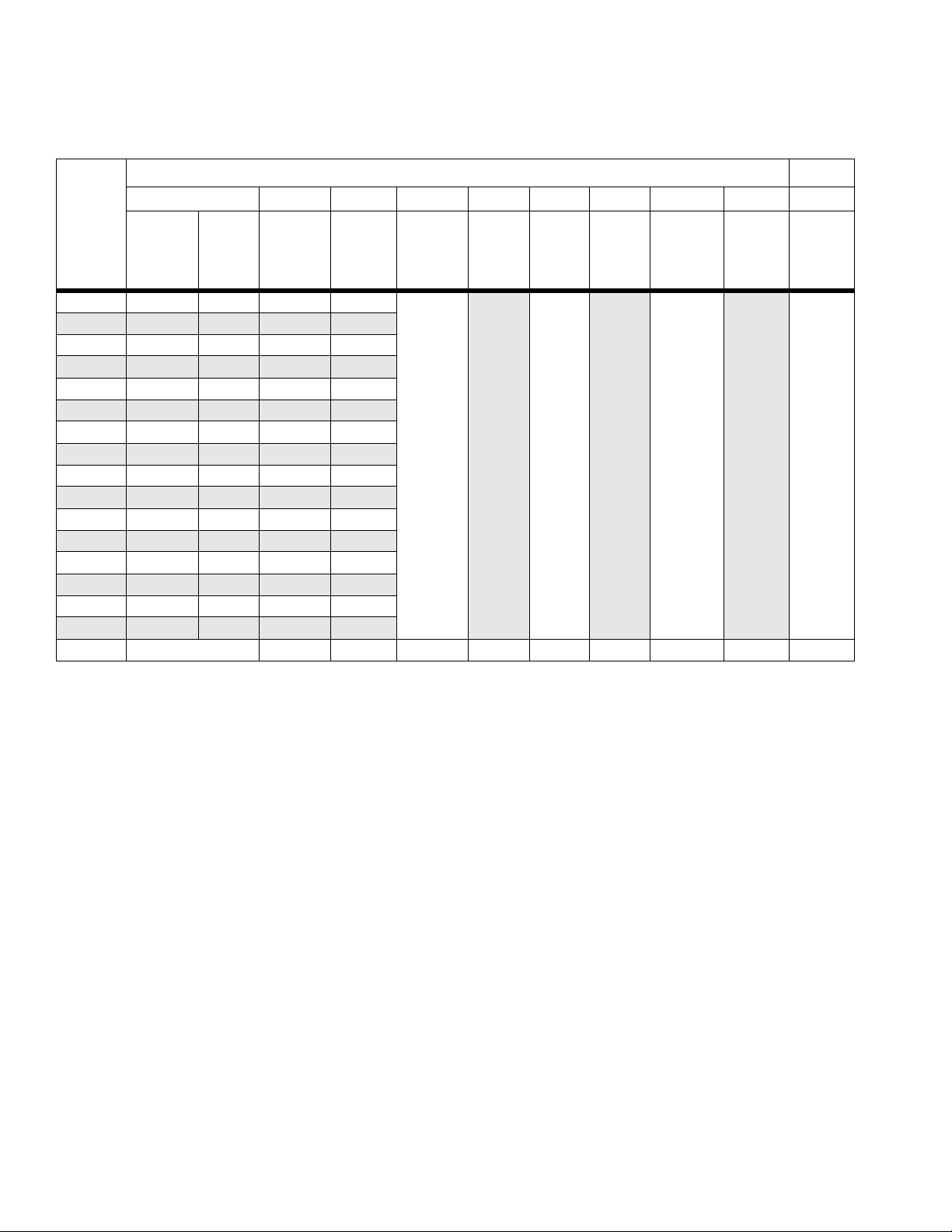
Pump Packages with L085C# Lowers (80:1 ratio)
Pump Packages with L085C# Lowers (80:1 ratio)
Reference Number and Description
302 303 304 305 306 307 308 309 310 311
Pump
Package
Lower
(see 311762)
P80DC1 L085C1 N34DN0
P80DC2 L085C2
P80DC3 L085C1 N34DN0
P80DC4 L085C2
P80EC1 L085C1 N34DT0
P80EC2 L085C2
P80EC3 L085C1 N34DT0
P80EC4 L085C2
P80LC1 L085C1 N34LN0
P80LC2 L085C2
P80LC3 L085C1 N34LN0
P80LC4 L085C2
P80MC1 L085C1 N34LT0
P80MC2 L085C2
P80MC3 L085C1 N34LT0
P80MC4 L085C2
Qty. 1 111313111
Built-in
Filter
✔
✔
✔
✔
✔
✔
✔
✔
Motor
(see 311238)
N34DN0
N34DN0
N34DT0
N34DT0
N34LN0
N34LN0
N34LT0
N34LT0
Air
Control
(NXT021)
(see
311239)
✔
✔
✔
✔
✔
✔
✔
✔
Coupling,
assy.
247167
(different
from all
other pack-
ages)
Rod,
tie
257150 197340 101712 244820 15H392 NXT112
Cover,
coupler
Nut,
lock
Clip,
hairpin w/
lanyard
Adapter,
rod
De-ice
Control
Knob
(5-pack)
44 311164M
Page 45
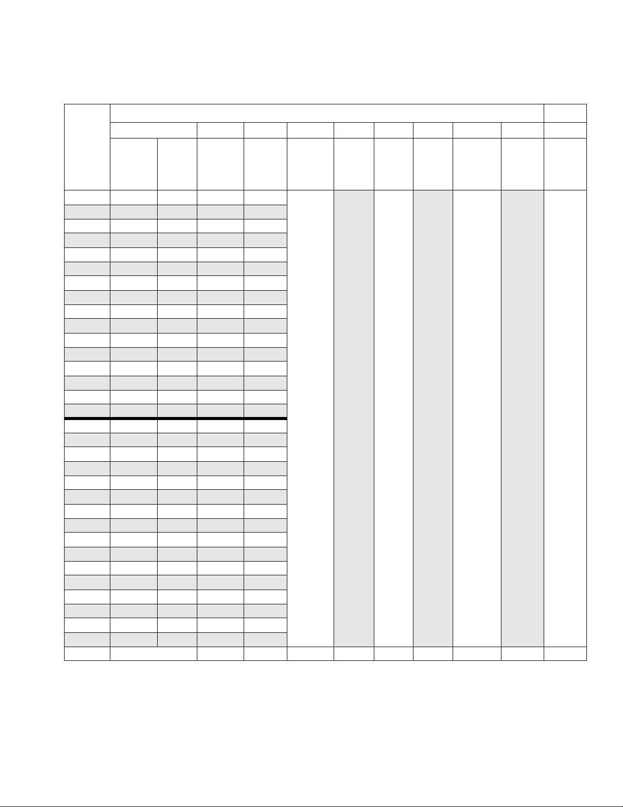
Pump Packages with L115C# Lowers (35:1, 55:1 ratio)
Pump Packages with L115C# Lowers (35:1, 55:1 ratio)
Reference Number and Description
302 303 304 305 306 307 308 309 310 311
Pump
Package
Lower
(see 311762)
P35DC1 L115C1 N22DN0
P35DC2 L115C2
P35DC3 L115C1 N22DN0
P35DC4 L115C2
P35EC1 L115C1 N22DT0
P35EC2 L115C2
P35EC3 L115C1 N22DT0
P35EC4 L115C2
P35LC1 L115C1 N22LN0
P35LC2 L115C2
P35LC3 L115C1 N22LN0
P35LC4 L115C2
P35MC1 L115C1 N22LT0
P35MC2 L115C2
P35MC3 L115C1 N22LT0
P35MC4 L115C2
P55DC1 L115C1 N34DN0
P55DC2 L115C2
P55DC3 L115C1 N34DN0
P55DC4 L115C2
P55EC1 L115C1 N34DT0
P55EC2 L115C2
P55EC3 L115C1 N34DT0
P55EC4 L115C2
P55LC1 L115C1 N34LN0
P55LC2 L115C2
P55LC3 L115C1 N34LN0
P55LC4 L115C2
P55MC1 L115C1 N34LT0
P55MC2 L115C2
P55MC3 L115C1 N34LT0
P55MC4 L115C2
Qty. 1 111313111
Built-in
Filter
✔
✔
✔
✔
✔
✔
✔
✔
✔
✔
✔
✔
✔
✔
✔
✔
Motor
(see 311238)
N22DN0
N22DN0
N22DT0
N22DT0
N22LN0
N22LN0
N22LT0
N22LT0
N34DN0
N34DN0
N34DT0
N34DT0
N34LN0
N34LN0
N34LT0
N34LT0
Air
Control
(NXT021)
(see
311239)
✔
✔
✔
✔
✔
✔
✔
✔
✔
✔
✔
✔
✔
✔
✔
✔
Coupling,
assy.
247167
(different
from all
other pack-
ages)
Rod,
tie
257150 197340 101712 244820 15H392 NXT112
Cover,
coupler
Nut,
lock
Clip,
hairpin w/
lanyard
Adapter,
rod
De-ice
Control
Knob
(5-pack)
311164M 45
Page 46
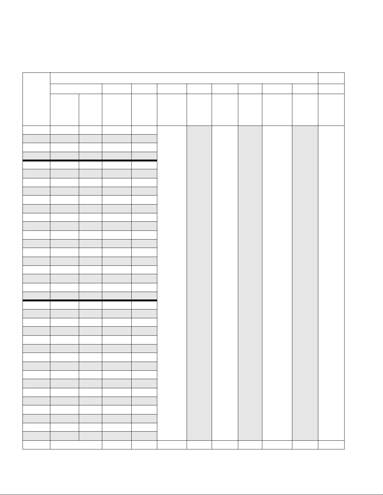
Pump Packages with L145C# and L14AC1 Lowers (31:1, 46:1, 90:1 ratio)
Pump Packages with L145C# and L14AC1 Lowers
(31:1, 46:1, 90:1 ratio)
Reference Number and Description
302 303 *304 305 306 307 308 309 310 311
Pump
Package
Lower
(see 311762)
P31LC1 L14AC1 N22LN0
P31MC1 L14AC1 N22LT0
P31DC1 L14AC1 N22DN0
P31EC1 L14AC1 N22DT0
P46DC1 L145C1 N34DN0
P46DC2 L145C2
P46DC3 L145C1 N34DN0
P46DC4 L145C2
P46EC1 L145C1 N34DT0
P46EC2 L145C2
P46EC3 L145C1 N34DT0
P46EC4 L145C2
P46LC1 L145C1 N34LN0
P46LC2 L145C2
P46LC3 L145C1 N34LN0
P46LC4 L145C2
P46MC1 L145C1 N34LT0
P46MC2 L145C2
P46MC3 L145C1 N34LT0
P46MC4 L145C2
P90DC1 L145C1 N65DN0
P90DC2 L145C2
P90DC3 L145C1 N65DN0
P90DC4 L145C2
P90EC1 L145C1 N65DT0
P90EC2 L145C2
P90EC3 L145C1 N65DT0
P90EC4 L145C2
P90LC1 L145C1 N65LN0
P90LC2 L145C2
P90LC3 L145C1 N65LN0
P90LC4 L145C2
P90MC1 L145C1 N65LT0
P90MC2 L145C2
P90MC3 L145C1 N65LT0
P90MC4 L145C2
Qty. 1 111313111
Built-in
Filter
✔
✔
✔
✔
✔
✔
✔
✔
✔
✔
✔
✔
✔
✔
✔
✔
Motor
(see 311238)
N34DN0
N34DN0
N34DT0
N34DT0
N34LN0
N34LN0
N34LT0
N34LT0
N65DN0
N65DN0
N65DT0
N65DT0
N65LN0
N65LN0
N65LT0
N65LT0
* NXT021 Air Control assemblies for P90xxx model pumps are equipped with safety relief valve 116643. Reorder this part number.
Air
Control
(NXT021)
(see
311239)
✔
✔
✔
✔
✔
✔
✔
✔
✔
✔
✔
✔
✔
✔
✔
✔
Coupling,
assy.
244819
Rod,
tie
257150 197340 101712 244820 15H392 NXT112
Cover,
coupler
Nut,
lock
Clip,
hairpin w/
lanyard
Adapter,
rod
De-ice
Control
Knob
(5-pack)
46 311164M
Page 47
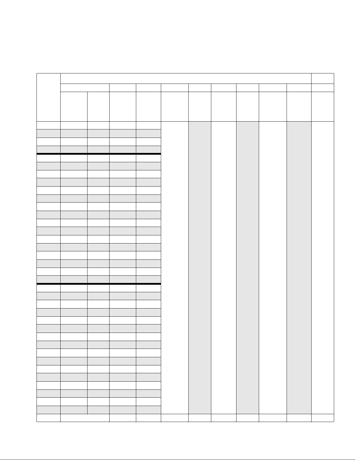
Pump Packages with L180C# and L18AC1 Lowers (24:1, 40:1, 70:1 ratio)
Pump Packages with L180C# and L18AC1 Lowers
(24:1, 40:1, 70:1 ratio)
Reference Number and Description
302 303 304 305 306 307 308 309 310 311
Pump
Package
Lower
(see 311762)
P24LC1 L18AC1 N22LN0
P24MC1 L18AC1 N22LT0
P24DC1 L18AC1 N22DN0
P24EC1 L18AC1 N22DT0
P40DC1 L180C1 N34DN0
P40DC2 L180C2
P40DC3 L180C1 N34DN0
P40DC4 L180C2
P40EC1 L180C1 N34DT0
P40EC2 L180C2
P40EC3 L180C1 N34DT0
P40EC4 L180C2
P40LC1 L180C1 N34LN0
P40LC2 L180C2
P40LC3 L180C1 N34LN0
P40LC4 L180C2
P40MC1 L180C1 N34LT0
P40MC2 L180C2
P40MC3 L180C1 N34LT0
P40MC4 L180C2
P70DC1 L180C1 N65DN0
P70DC2 L180C2
P70DC3 L180C1 N65DN0
P70DC4 L180C2
P70EC1 L180C1 N65DT0
P70EC2 L180C2
P70EC3 L180C1 N65DT0
P70EC4 L180C2
P70LC1 L180C1 N65LN0
P70LC2 L180C2
P70LC3 L180C1 N65LN0
P70LC4 L180C2
P70MC1 L180C1 N65LT0
P70MC2 L180C2
P70MC3 L180C1 N65LT0
P70MC4 L180C2
Qty. 1111313111
Built-in
Filter
✔
✔
✔
✔
✔
✔
✔
✔
✔
✔
✔
✔
✔
✔
✔
✔
Motor
(see 311238)
N34DN0
N34DN0
N34DT0
N34DT0
N34LN0
N34LN0
N34LT0
N34LT0
N65DN0
N65DN0
N65DT0
N65DT0
N65LN0
N65LN0
N65LT0
N65LT0
Air
Control
(NXT021)
(see
311239)
✔
✔
✔
✔
✔
✔
✔
✔
✔
✔
✔
✔
✔
✔
✔
✔
Coupling,
assy.
244819
Rod,
tie
257150 197340 101712 244820 15H392 NXT112
Cover,
coupler
Nut,
lock
Clip,
hairpin w/
lanyard
Adapter,
rod
De-ice
Control
Knob
(5-pack)
311164M 47
Page 48
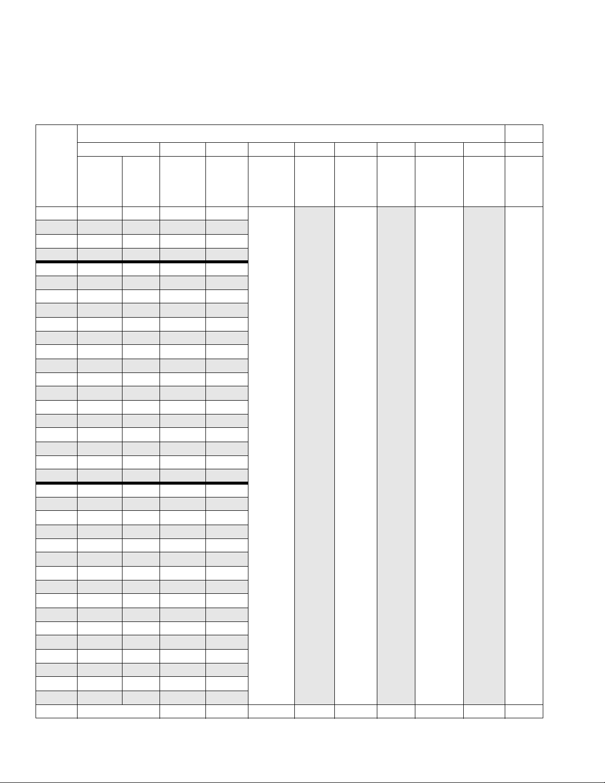
Pump Packages with L220C# Lowers (21:1, 30:1, 60:1 ratio)
Pump Packages with L220C# Lowers
(21:1, 30:1, 60:1 ratio)
Reference Number and Description
302 303 304 305 306 307 308 309 310 311
Pump
Package
Lower
(see 311762)
P21DC1 L22AC1 N22DN0
P21EC1 L22AC1 N22DT0
P21LC1 L22AC1 N22LN0
P21MC1 L22AC1 N22LT0
P30DC1 L220C1 N34DN0
P30DC2 L220C2
P30DC3 L220C1 N34DN0
P30DC4 L220C2
P30EC1 L220C1 N34DT0
P30EC2 L220C2
P30EC3 L220C1 N34DT0
P30EC4 L220C2
P30LC1 L220C1 N34LN0
P30LC2 L220C2
P30LC3 L220C1 N34LN0
P30LC4 L220C2
P30MC1 L220C1 N34LT0
P30MC2 L220C2
P30MC3 L220C1 N34LT0
P30MC4 L220C2
P60DC1 L220C1 N65DN0
P60DC2 L220C2
P60DC3 L220C1 N65DN0
P60DC4 L220C2
P60EC1 L220C1 N65DT0
P60EC2 L220C2
P60EC3 L220C1 N65DT0
P60EC4 L220C2
P60LC1 L220C1 N65LN0
P60LC2 L220C2
P60LC3 L220C1 N65LN0
P60LC4 L220C2
P60MC1 L220C1 N65LT0
P60MC2 L220C2
P60MC3 L220C1 N65LT0
P60MC4 L220C2
Qty. 1111313111
Built-in
Filter
✔
✔
✔
✔
✔
✔
✔
✔
✔
✔
✔
✔
✔
✔
✔
✔
Motor
(see 311238)
N34DN0
N34DN0
N34DT0
N34DT0
N34LN0
N34LN0
N34LT0
N34LT0
N65DN0
N65DN0
N65DT0
N65DT0
N65LN0
N65LN0
N65LT0
N65LT0
Air
Control
(NXT021)
(see
311239)
✔
✔
✔
✔
✔
✔
✔
✔
✔
✔
✔
✔
✔
✔
✔
✔
Coupling,
assy.
244819
Rod,
tie
257150 197340 101712 244820 15H392 NXT112
Cover,
coupler
Nut,
lock
Clip,
hairpin w/
lanyard
Adapter,
rod
De-ice
Control
Knob
(5-pack)
48 311164M
Page 49
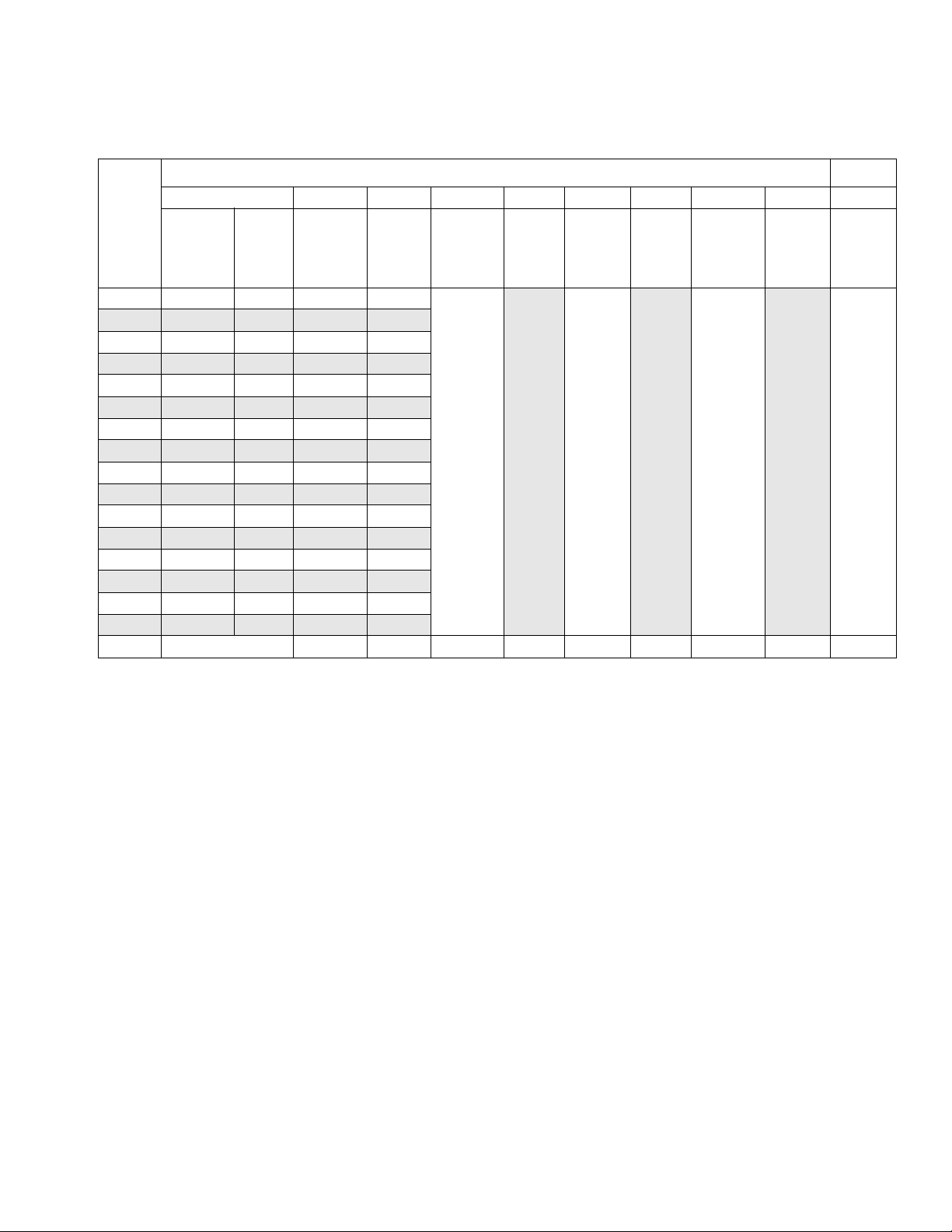
Pump Packages with L250C# Lowers (50:1 ratio)
Pump Packages with L250C# Lowers (50:1 ratio)
Reference Number and Description
302 303 304 305 306 307 308 309 310 311
Pump
Package
Lower
(see 311762)
P50DC1 L250C1 N65DN0
P50DC2 L250C2
P50DC3 L250C1 N65DN0
P50DC4 L250C2
P50EC1 L250C1 N65DT0
P50EC2 L250C2
P50EC3 L250C1 N65DT0
P50EC4 L250C2
P50LC1 L250C1 N65LN0
P50LC2 L250C2
P50LC3 L250C1 N65LN0
P50LC4 L250C2
P50MC1 L250C1 N65LT0
P50MC2 L250C2
P50MC3 L250C1 N65LT0
P50MC4 L250C2
Qty. 1 1 1 1 313 1 1 1
Built-in
Filter
✔
✔
✔
✔
✔
✔
✔
✔
Motor
(see 311238)
N65DN0
N65DN0
N65DT0
N65DT0
N65LN0
N65LN0
N65LT0
N65LT0
Air
Control
(NXT021)
(see
311239)
✔
✔
✔
✔
✔
✔
✔
✔
Coupling,
assy.
244819
Rod,
tie
257150 197340 101712 244820 15H392 NXT112
Cover,
coupler
Nut,
lock
Clip,
hairpin w/
lanyard
Adapter,
rod
De-ice
Control
Knob
(5-pack)
311164M 49
Page 50
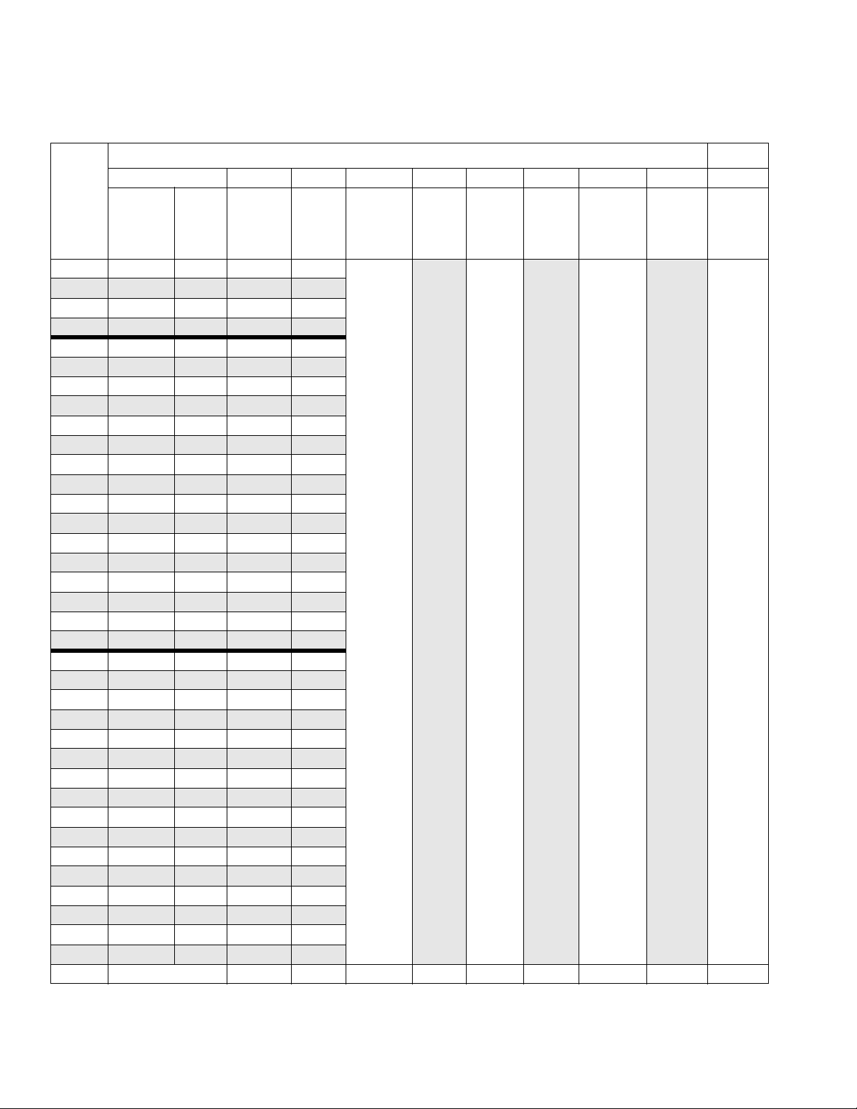
Pump Packages with L290C# Lowers (16:1, 25:1, 45:1 ratio)
Pump Packages with L290C# Lowers (16:1, 25:1, 45:1
Reference Number and Description
302 303 304 305 306 307 308 309 310 311
Pump
Package
Lower
(see 311762)
P16DC1 L29AC1 N22DN0
P16EC1 L29AC1 N22DT0
P16LC1 L29AC1 N22LN0
P16MC1 L29AC1 N22LT0
P25DC1 L290C1 N34DN0
P25DC2 L290C2
P25DC3 L290C1 N34DN0
P25DC4 L290C2
P25EC1 L290C1 N34DT0
P25EC2 L290C2
P25EC3 L290C1 N34DT0
P25EC4 L290C2
P25LC1 L290C1 N34LN0
P25LC2 L290C2
P25LC3 L290C1 N34LN0
P25LC4 L290C2
P25MC1 L290C1 N34LT0
P25MC2 L290C2
P25MC3 L290C1 N34LT0
P25MC4 L290C2
P45DC1 L290C1 N65DN0
P45DC2 L290C2
P45DC3 L290C1 N65DN0
P45DC4 L290C2
P45EC1 L290C1 N65DT0
P45EC2 L290C2
P45EC3 L290C1 N65DT0
P45EC4 L290C2
P45LC1 L290C1 N65LN0
P45LC2 L290C2
P45LC3 L290C1 N65LN0
P45LC4 L290C2
P45MC1 L290C1 N65LT0
P45MC2 L290C2
P45MC3 L290C1 N65LT0
P45MC4 L290C2
Qty. 1 111313 1 11
Built-in
Filter
✔
✔
✔
✔
✔
✔
✔
✔
✔
✔
✔
✔
✔
✔
✔
✔
Motor
(see 311238)
N34DN0
N34DN0
N34DT0
N34DT0
N34LN0
N34LN0
N34LT0
N34LT0
N65DN0
N65DN0
N65DT0
N65DT0
N65LN0
N65LN0
N65LT0
N65LT0
Air
Control
(NXT021)
(see
311239)
✔
✔
✔
✔
✔
✔
✔
✔
✔
✔
✔
✔
✔
✔
✔
✔
Coupling,
assy.
244819
Rod,
tie
257150 197340 101712 244820 15H392 NXT112
Cover,
coupler
Nut,
lock
Clip,
hairpin w/
lanyard
Adapter,
rod
ratio)
De-ice
Control
Knob
(5-pack)
50 311164M
Page 51
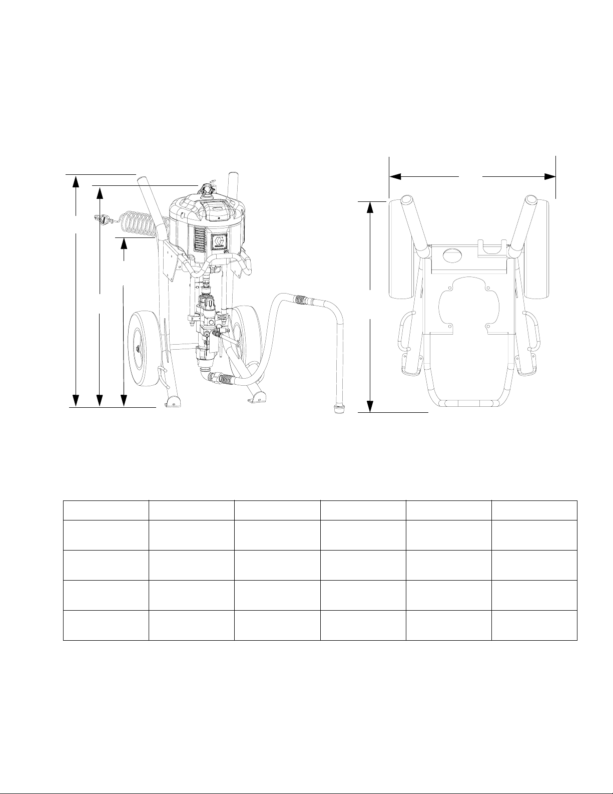
Dimensions
Sprayer (Cart Mounted) Packages
Dimensions
Model X60DH3 Shown
A
C
B
KEY:
HD = Heavy Duty Cart
LW = Light Weight Cart
r_x25dh1_x45dh1_311164_47f2
Top View - Heavy Duty Cart Shown
E
D
r_x25dh1_x45dh1_311164_47f
All Xtreme Sprayer (Cart Mounted) Packages
Mount A B C D E
43.69 in.
HD
LW
HD with Hopper
LW with Hopper
311164M 51
(1109.73 mm)
44.86 in.
(1139.44 mm)
43.69 in.
(1109.73 mm)
44.86 in.
(1139.44 mm)
46.0 in.
(1168.4 mm)
45.5 in.
(1115.7 mm)
46.0 in.
(1168.4 mm)
45.5 in.
(1115.7 mm)
32.0 in.
(812.8 mm)
31.3 in.
(795 mm)
32.0 in.
(812.8 mm)
31.3 in.
(795 mm)
35.0 in.
(889 mm)
34.0 in.
(863.6 mm)
45.0 in.
(1143 mm)
44.0 in.
(1117.6 mm)
25.72 in.
(653.3 mm)
27.09 in.
(688.1 mm)
25.72 in.
(653.3 mm)
27.09 in.
(688.1 mm)
Page 52
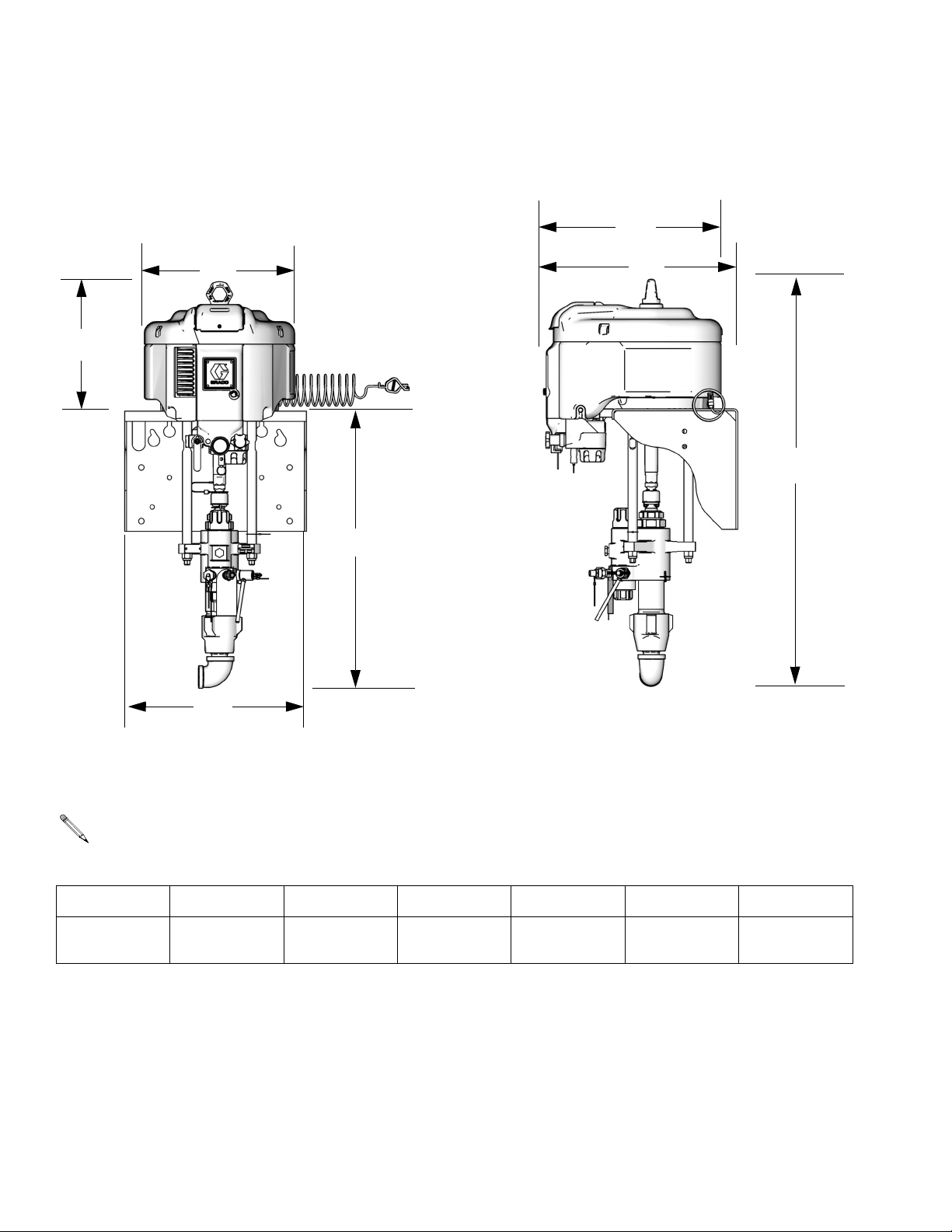
Dimensions
Wall Mount Packages and Pump Packages
A
Front View
G
Side View
F
D
EE
C
B
Wall Mount Dimensions
NOTE: Dimensions based on largest air motor
and lower combination.
ABCDE FG
14.0 in.
(355.6 mm)
17.75 in.
(450.6 mm)
29.0 in.
(736.6 mm)
TI8424a
19.25 in.
(489 mm)
43.0 in.
(1092.2 mm)
18.9 in.
(480 mm)
TI8425a
16.2 in.
(410 mm)
52 311164M
Page 53
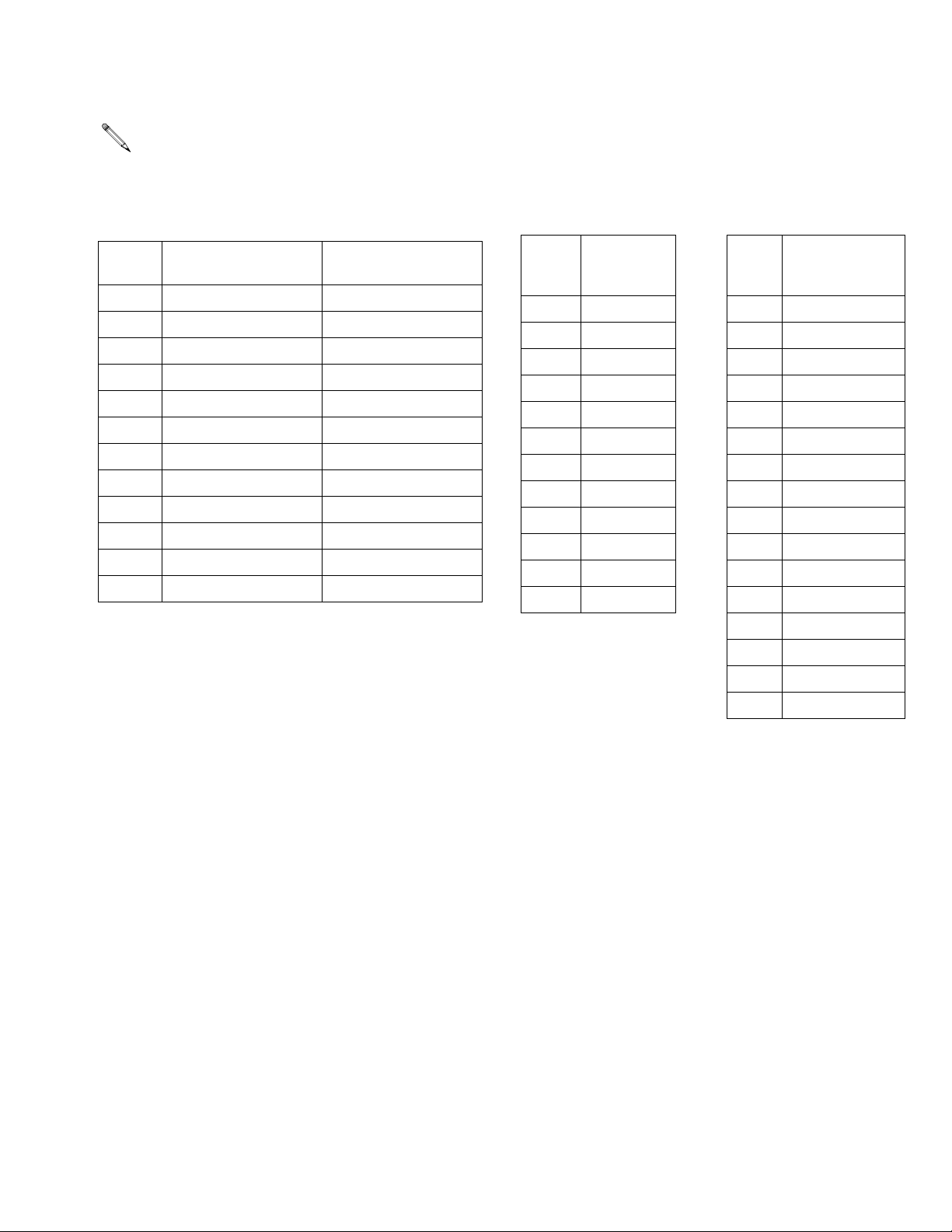
Weights
NOTE: Weights are approximate and do not
include hoses or guns.
Dimensions
Sprayer (Cart Mounted)
Packages
Heavy Duty Cart
Ratio
25:1 228.4 (103.6) 196.1 (89.0)
30:1 227.4 (103.1) 195.1 (88.5)
35:1 209.9 (95.2) 177.6 (80.6)
40:1 223.4 (101.3) 191.1 (86.7)
45:1 247.4 (112.2) 215.1 (97.6)
46:1 223.4 (101.3) 191.1 (86.7)
50:1 246.4 (111.8) 214.1 (97.1)
55:1 211.4 (95.9) 179.1 (81.2)
60:1 246.4 (111.8) 214.1 (97.1)
70:1 242.4 (109.9) 210.1 (95.3)
80:1 211.4 (95.9) 179.1 (81.2)
90:1 242.4 (109.9) 210.1 (95.3)
lbs (kg)
Light Weight Cart
lbs (kg)
Wall Mount
Packages
Ratio lbs (kg) Ratio
25:1 159.0 (72.1) 16:1 99.4 (45.1)
30:1 158.0 (71.7) 21:1 98.4 (44.6)
35:1 140.5 (63.7) 24:1 94.4 (42.8)
40:1 154.0 (69.9) 25:1 103.4 (46.9)
45:1 178.0 (80.8) 30:1 102.4 (46.4)
46:1 154.0 (69.9) 31:1 94.4 (42.8)
50:1 177.0 (80.3) 35:1 84.4 (38.3)
55:1 142.0 (64.4) 40:1 98.4 (44.6)
60:1 177.0 (80.3) 45:1 122.4 (55.5)
70:1 173.0 (78.5) 46:1 98.4 (44.6)
80:1 142.0 (64.4) 50:1 121.4 (55.1)
90:1 173.0 (78.5) 55:1 88.4 (40.1)
Pump Assembly
Packages
No Filter, No Air
Controls❄
lbs (kg)
60:1 121.4 (55.1)
70:1 117.4 (53.3)
80:1 88.4 (40.1)
90:1 117.4 (53.3)
❄ Add 10 lbs (4.54 kg) for built-in filter. Add 5 lbs (2.27 kg)
for air controls.
311164M 53
Page 54
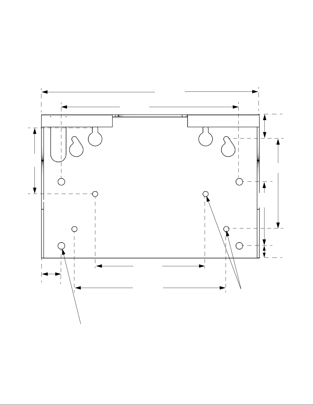
Mounting Hole Diagram
Mounting Hole Diagram
Wall Mount Bracket
14.5 in.
(368.3 mm)
5.4 in.
(136.5 mm)
17.8 in.
(450.9 mm)
2.0 in.
(50.8 mm)
7.4 in.
(187.3 mm)
1.6 in.
(41.4 mm)
1/2 in. (12.7 mm) diameter
holes for mounting to stand
9.0 in.
(228.6 mm)
12.4 in.
(314.3 mm)
5.3 in.
(133.4 mm)
1.0 in.
(25.4 mm)
7/16 in. (11 mm)
diameter holes for
mounting to wall
TI8614a
54 311164M
Page 55

Accessories
Adapter Plate 247312
Adapter plate is required to mount pump assemblies
with an NXT2200 air motor to cart or wall mount bracket.
NXT021 Air Control Module
Includes Safety Relief Valve 113498 (pressure relief at
110 psi (7.7 MPa, 77 bar)). If you have a 90:1 pump
package, also order Safety Relief Valve 116643 (pressure relief at 90 psi (6.3 MPa, 63 bar)).
DataTrak Upgrade Kits
NXT206 kit for NXT2200 air motors
Accessories
NXT306 kit for NXT3400 air motors
NXT606 kit for NXT6500 air motors
Hopper Kit 288347
Hopper kit attaches to cart mounted sprayers. See Hopper Assembly, page 26, for illustration of kit and kit
parts.
311164M 55
Page 56
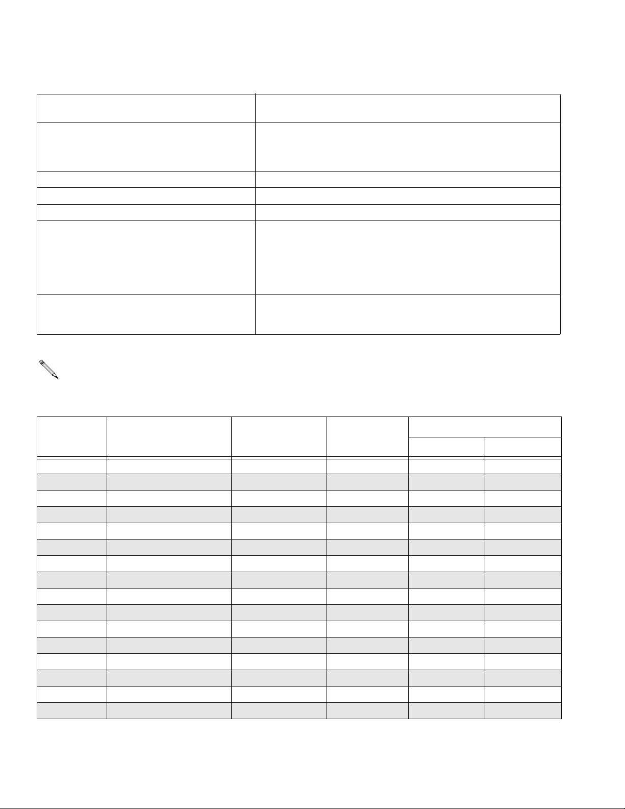
Technical Data
Technical Data
Maximum air inlet pressure Models with 16:1 - 80:1 pressure ratios: 100 psi (0.7 MPa, 7 bar).
Models with a 90:1 pressure ratio: 80 psi (0.55 MPa, 5.5 bar).
Air motor piston diameter NXT Model 6500: 10.375 in. (264 mm)
NXT Model 3400: 7.5 in. (191 mm)
NXT Model 2200: 6.0 in. (152 mm)
Stroke length 4.75 in. (120 mm)
Air Inlet Size 3/4 npt(f)
Fluid Inlet Size 1-1/4 npt(m)
Fluid Outlet Size All pumps with built-in filters (2 outlet ports): 1/2 npt(m)
Pumps without built-in filters (1 outlet port):
85cc and 115cc pumps: 1/2 npt(f)
145cc and 180cc pumps: 3/4 npt(f)
220cc, 250cc, and 290cc pumps: 1 npt(f)
Maximum pump speed
(Do not exceed maximum recommended speed
of fluid pump, to prevent premature pump wear)
60 cycles per minute
NOTE: See NXT Motor manual (311238) for
sound data.
Maximum Working Pressure and Flow Rate at Full Air Pressure (100 psi)
Maximum Working
Ratio
16:1 1520 (10.5, 105) 2200 290 2.3 (8.7) 4.6 (17.0)
21:1 2025 (14.0, 140) 2200 220 1.74 (6.6) 3.4 (12.9)
24:1 2400 (16.5, 165) 2200 180 1.43 (5.4) 2.9 (11.0)
25:1 2375 (16.4, 164) 3400 290 2.3 (8.7) 4.6 (17.0)
30:1 3150 (21.7, 217) 3400 220 1.74 (6.6) 3.4 (12.9)
31:1 3000 (20.7, 207) 2200 145 1.15 (4.4) 2.3 (8.7)
35:1 3800 (26.2, 262) 2200 115 0.95 (3.6) 2.0 (7.6)
40:1 3800 (26.2, 262) 3400 180 1.43 (5.4) 2.9 (11.0)
45:1 4500 (31.0, 310) 6500 290 2.3 (8.7) 4.6 (17.0)
46:1 4750 (32.7, 327) 3400 145 1.15 (4.4) 2.3 (8.7)
50:1 5000 (34.5, 345) 6500 250 2.0 (7.6) 4.0 (15.2)
55:1 5600 (38.6, 386) 3400 115 0.95 (3.6) 2.0 (7.6)
60:1 6000 (41.7, 417) 6500 220 1.74 (6.6) 3.4 (12.9)
70:1 7250 (50.0, 500) 6500 180 1.43 (5.4) 2.9 (11.0)
80:1 7250 (50.0, 500) 3400 85 0.8 (3.0) 1.5 (5.7)
90:1 7250 (50.0, 500) 6500 145 1.15 (4.4)* 2.3 (8.7)*
Pressure psi (MPa, bar) NXT Air Motor
Lower
(cc per cycle)
Flow Rate gpm (lpm)
30 cpm 60 cpm
* At 80 psi (0.55 MPa, 5.5 bar)
56 311164M
Page 57
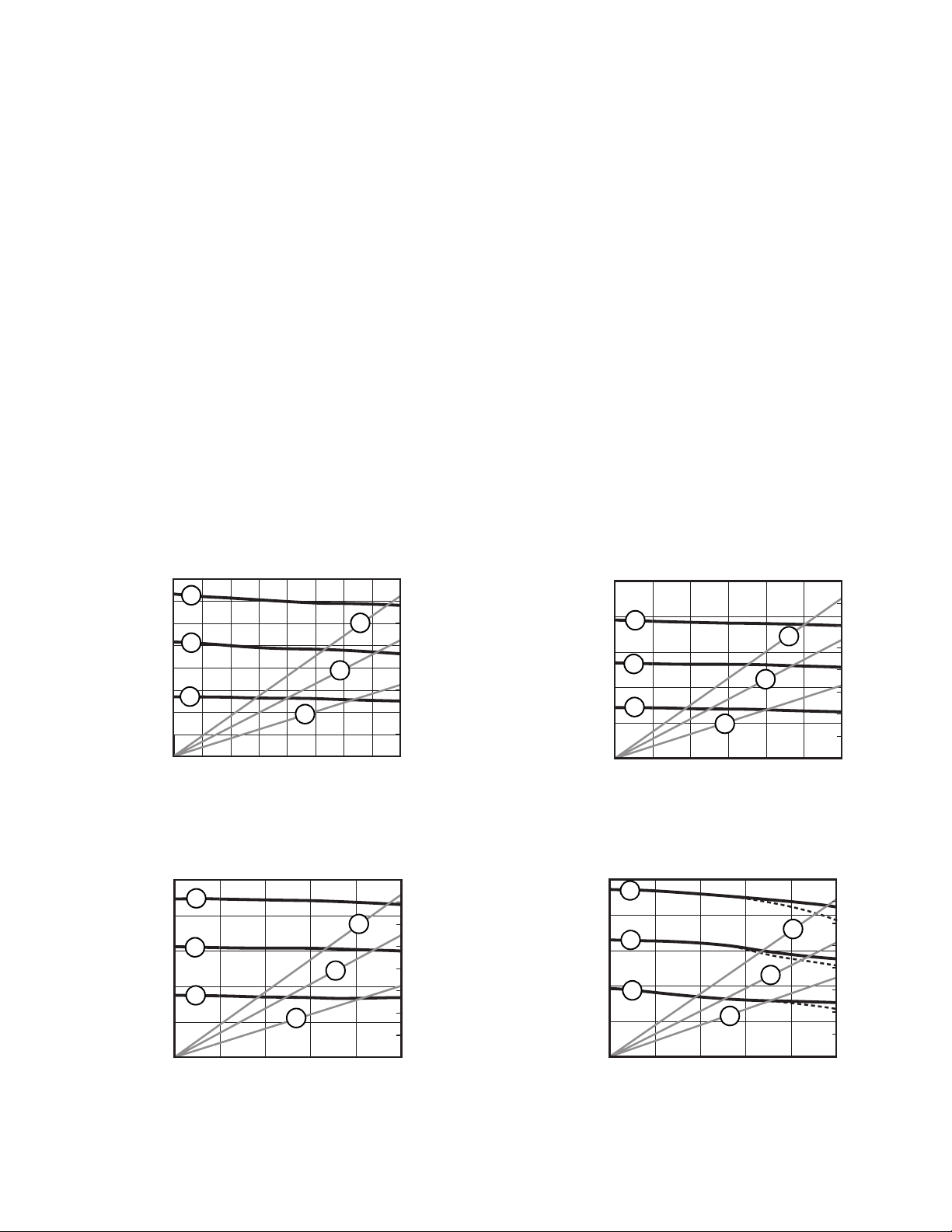
Pump Package Performance Charts
Pump Package Performance Charts
Calculate Fluid Outlet Pressure
To calculate fluid outlet pressure (psi/MPa/bar) at a specific fluid flow (gpm/lpm) and operating air pressure
(psi/MPa/bar), use the following instructions and pump
data charts.
1. Locate desired flow along bottom of chart.
2. Follow vertical line up to intersection with selected
fluid outlet pressure curve. Follow left to scale to
read fluid outlet pressure.
Key: Air Pressure
A 100 psi (0.7 MPa, 7 bar)
B 70 psi (0.5 MPa, 7.8 bar)
C 40 psi (0.3 MPa, 2.8 bar)
Dashed lines indicate low noise motors.
16:1 Xtreme Pumps
1600
(11.2, 112)
(8.4, 84)
(5.6, 56)
(2.8, 28)
Fluid Pressure in psig (MPa, bar)
A
1200
B
800
B
C
400
02.0
(3.8)
Fluid Flow in gpm (lpm)
(7.6)
C
3.01.0
(11.4)
A
80
(2.2)
60
(1.7)
4.0
(15.2)
40
(1.1)
20
(0.6)
Air Flow in SCFM (m
3
/min)
Calculate Pump Air Flow/Consumption
To calculate pump air flow/consumption (scfm or
3
/min) at a specific fluid flow (gpm/lpm) and air pres-
m
sure (psi/MPa/bar), use the following instructions and
pump data charts.
1. Locate desired flow along bottom of chart.
2. Follow vertical line up to intersection with selected
air flow/consumption curve. Follow right to scale to
read air flow/consumption.
21:1 Xtreme Pumps
80
(2.2)
60
(1.7)
40
(1.1)
20
(0.6)
3.0
(11.4)
(17.5, 175)
(10.5, 105)
(3.5, 35)
Fluid Pressure in psig (MPa, bar)
2500
1500
500
A
A
B
B
C
C
0
1.0
(3.8)
Fluid Flow in gpm (lpm)
2.0
(7.6)
Air Flow in SCFM (m
3
/min)
25:1 Xtreme Pumps
A
B
C
1.0
(3.8)
Fluid Flow in gpm (lpm)
C
(11.4)
160
Air Flow in SCFM (m
(4.5)
5.03.0
(19.0)
120
(3.4)
80
(2.2)
40
(1.1)
3
/min)
A
B
(17.5, 175)
(10.5, 105)
(3.5, 35)
Fluid Pressure in psig (MPa, bar)
2500
1500
500
24:1 Xtreme Pumps
80
Air Flow in SCFM (m
A
A
(2.2)
60
(1.7)
B
3.0
(11.4)
40
(1.1)
20
(0.6)
3
/min)
B
C
C
1.0
0
(3.8)
Fluid Flow in gpm (lpm)
2.0
(7.6)
(17.5, 175)
(10.5, 105)
(3.5, 35)
Fluid Pressure in psig (MPa, bar)
2500
1500
500
0
311164M 57
Page 58
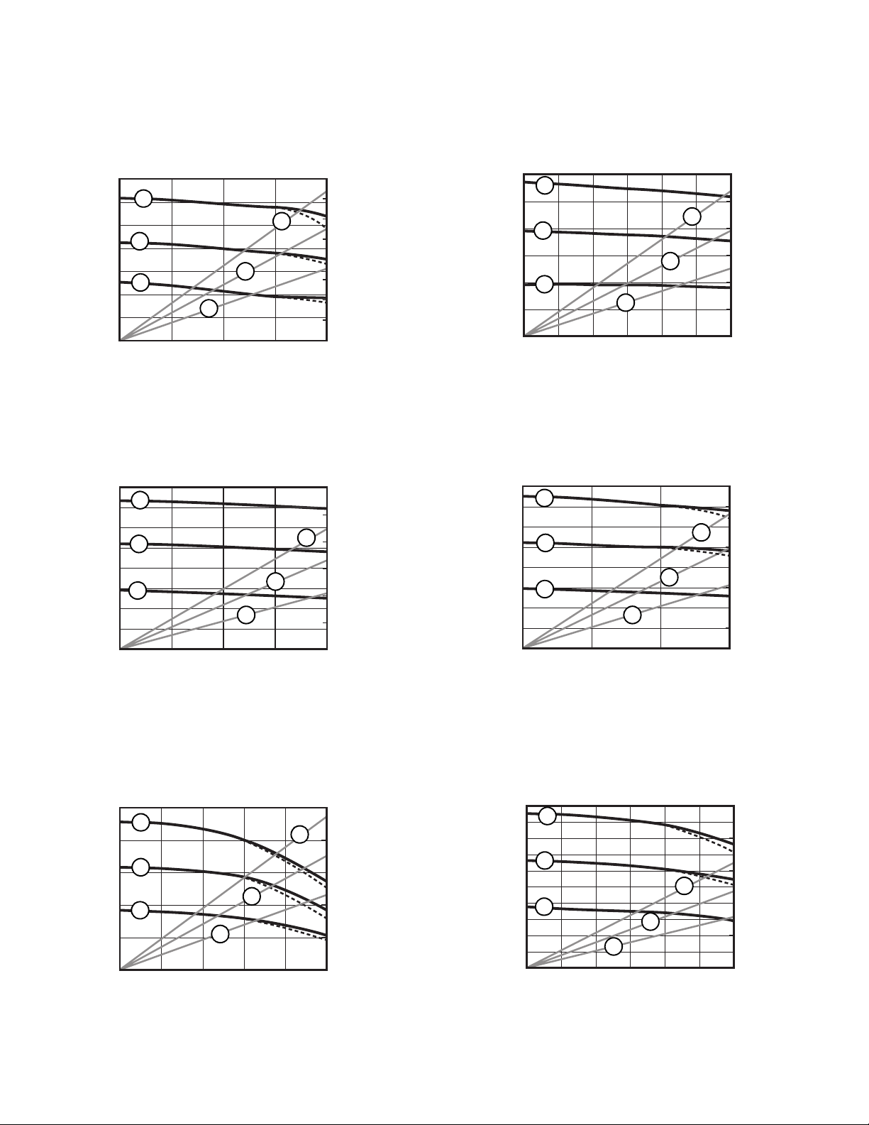
Pump Package Performance Charts
Pump Package Performance Charts (cont.)
(24.5, 245)
(17.5, 175)
(10.5, 105)
(3.5, 35)
Fluid Pressure in psig (MPa, bar)
(28.0, 280)
(21.0, 210)
(14.0, 140)
(7.0, 70)
3500
2500
1500
500
4000
3000
2000
1000
30:1 Xtreme Pumps
160
Air Flow in SCFM (m
A
A
(4.5)
120
(3.4)
B
C
B
C
0
1.0
(3.8) (7.6)
2.0
3.0
(11.4)
80
(2.2)
4.0
(15.2)
40
(1.1)
3
/min)
3000
(21.0, 210)
2000
(14.0, 140)
1000
(7.0, 70)
Fluid Pressure in psig (MPa, bar)
0
Fluid Flow in gpm (lpm)
35:1 Xtreme Pumps
120
Air Flow in SCFM (m
A
B
C
B
C
(3.4)
A
80
(2.2)
40
3
(1.1)
/min)
4000
(28.0, 280)
3000
(21.0, 210)
2000
(14.0, 140)
1000
(7.0, 70)
31:1 Xtreme Pumps
A
B
C
C
1.0
(3.8) (7.6)
Fluid Flow in gpm (lpm)
40:1 Xtreme Pumps
A
B
C
Air Flow in SCFM (m
120
(3.4)
A
80
(2.2)
B
40
3
/min)
(1.1)
2.0
B
C
3.0
(11.4)
160
Air Flow in SCFM (m
(4.5)
120
A
(3.4)
80
(2.2)
3
/min)
40
(1.1)
Fluid Pressure in psig (MPa, bar)
(35.0, 350)
(28.0, 280)
(21.0, 210)
(14.0, 140)
(7.0, 70)
Fluid Pressure in psig (MPa, bar)
5000
4000
3000
2000
1000
0
0.5
(1.9)
Fluid Flow in gpm (lpm)
45:1 Xtreme Pumps
A
B
C
1.0
0
(3.8)
Fluid Flow in gpm (lpm)
1.0
(3.8)
C
(11.4)
1.5
(5.7)
2.0
(7.6)
Fluid Pressure in psig (MPa, bar)
0
(3.8)
2.0
(7.6)
3.01.0
(11.4)
Fluid Flow in gpm (lpm)
46:1 Xtreme Pumps
Air Flow in SCFM (m
250
(7.0)
A
150
(4.2)
B
3
/min)
50
(1.4)
5.03.0
(19.0)
(35.0, 350)
(28.0, 280)
(21.0, 210)
(14.0, 140)
(7.0, 70)
Fluid Pressure in psig (MPa, bar)
5000
4000
3000
2000
1000
A
B
A
C
B
C
0
1.0
(3.8) (7.6)
2.0
Fluid Flow in gpm (lpm)
250
(7.0)
150
(4.2)
50
(1.4)
3.0
(11.4)
Air Flow in SCFM (m
3
/min)
58 311164M
Page 59
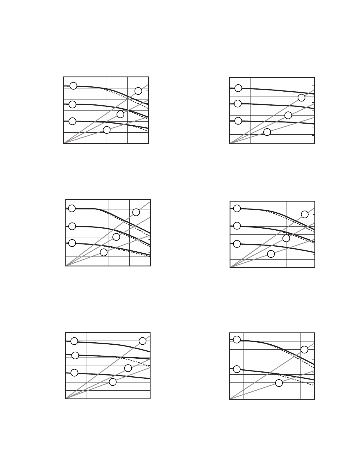
Pump Package Performance Charts (cont.)
Pump Package Performance Charts
6000
(42.0, 420)
4000
(28.0, 280)
2000
(14.0, 140)
Fluid Pressure in psig (MPa, bar)
(49.0, 490)
(35.0, 350)
(21.0, 210)
(7.0, 70)
Fluid Pressure in psig (MPa, bar)
50:1 Xtreme Pumps
A
B
C
C
01.0 4.02.0 3.0
7000
(3.8)
(7.6)
Fluid Flow in gpm (lpm)
60:1 Xtreme Pumps
A
5000
B
3000
C
1000
0
1.0 2.0 3.0 4.0
(3.8)
C
(7.6)
Fluid Flow in gpm (lpm)
B
(11.4)
B
(11.4) (15.2)
250
Air Flow in SCFM (m
(7.0)
200
A
(5.6)
150
(4.2)
100
(2.8)
3
/min)
50
(1.4)
(15.2)
250
Air Flow in SCFM (m
(7.0)
A
200
(5.6)
150
(4.2)
100
(2.8)
50
(1.4)
3
/min)
(49.0, 490)
(35.0, 350)
(21.0, 210)
(7.0, 70)
Fluid Pressure in psig (MPa, bar)
(56.0, 560)
(42.0, 420)
(28.0, 280)
(14.0, 140)
Fluid Pressure in psig (MPa, bar)
7000
A
5000
B
3000
C
1000
0
8000
A
6000
B
4000
C
2000
02.03.01.0
A
B
C
0.5 1.0 1.5 2.0
(1.9)
(3.8)
(5.7)
(7.6)
Fluid Flow in gpm (lpm)
70:1 Xtreme Pumps
A
B
C
(3.8) (7.6) (11.4)
Fluid Flow in gpm (lpm)
160
(4.5)
120
(3.4)
80
(2.2)
40
(1.1)
250
(7.0)
200
(5.6)
150
(4.2)
100
(2.8)
50
(1.4)
Air Flow in SCFM (m
3
/min)
Air Flow in SCFM (m
3
/min)
55:1 Xtreme Pumps
Key: 90:1 Pumps Air Pressure
B 80 psi (0.56 MPa, 5.6 bar)
C 40 psi (0.28 MPa, 2.8 bar)
(56.0, 560)
(42.0, 420)
(28.0, 280)
(14.0, 140)
Fluid Pressure in psig (MPa, bar)
8000
6000
4000
2000
80:1 Xtreme Pumps
160
Air Flow in SCFM (m
(4.5)
B
(5.7)
A
120
(3.4)
80
(2.2)
3
/min)
40
(1.1)
(7.6)
A
B
C
C
0
0.5 1.0 1.5 2.0
(1.9)
(3.8)
Fluid Flow in gpm (lpm)
(56.0, 560)
(42.0, 420)
(28.0, 280)
(14.0, 140)
Fluid Pressure in psig (MPa, bar)
8000
6000
4000
2000
0
90:1 Xtreme Pumps
B
C
1.0 2.0 3.0
(3.8)
Fluid Flow in gpm (lpm)
250
Air Flow in SCFM (m
(7.0)
200
B
(5.6)
150
(4.2)
100
(2.8)
3
C
(7.6)
/min)
50
(1.4)
(11.4)
311164M 59
Page 60

Graco Standard Warranty
Graco warrants all equipment referenced in this document which is manufactured by Graco and bearing its name to be free from defects in
material and workmanship on the date of sale to the original purchaser for use. With the exception of any special, extended, or limited warranty
published by Graco, Graco will, for a period of twelve months from the date of sale, repair or replace any part of the equipment determined by
Graco to be defective. This warranty applies only when the equipment is installed, operated and maintained in accordance with Graco40
s written recommendations.
This warranty does not cover, and Graco shall not be liable for general wear and tear, or any malfunction, damage or wear caused by faulty
installation, misapplication, abrasion, corrosion, inadequate or improper maintenance, negligence, accident, tampering, or substitution of
non-Graco component parts. Nor shall Graco be liable for malfunction, damage or wear caused by the incompatibility of Graco equipment with
structures, accessories, equipment or materials not supplied by Graco, or the improper design, manufacture, installation, operation or
maintenance of structures, accessories, equipment or materials not supplied by Graco.
This warranty is conditioned upon the prepaid return of the equipment claimed to be defective to an authorized Graco distributor for verification of
the claimed defect. If the claimed defect is verified, Graco will repair or replace free of charge any defective parts. The equipment will be returned
to the original purchaser transportation prepaid. If inspection of the equipment does not disclose any defect in material or workmanship, repairs will
be made at a reasonable charge, which charges may include the costs of parts, labor, and transportation.
THIS WARRANTY IS EXCLUSIVE, AND IS IN LIEU OF ANY OTHER WARRANTIES, EXPRESS OR IMPLIED, INCLUDING BUT NOT LIMITED
TO WARRANTY OF MERCHANTABILITY OR WARRANTY OF FITNESS FOR A PARTICULAR PURPOSE.
Graco’s sole obligation and buyer’s sole remedy for any breach of warranty shall be as set forth above. The buyer agrees that no other remedy
(including, but not limited to, incidental or consequential damages for lost profits, lost sales, injury to person or property, or any other incidental or
consequential loss) shall be available. Any action for breach of warranty must be brought within two (2) years of the date of sale.
GRACO MAKES NO WARRANTY, AND DISCLAIMS ALL IMPLIED WARRANTIES OF MERCHANTABILITY AND FITNESS FOR A
PARTICULAR PURPOSE, IN CONNECTION WITH ACCESSORIES, EQUIPMENT, MATERIALS OR COMPONENTS SOLD BUT NOT
MANUFACTURED BY GRACO. These items sold, but not manufactured by Graco (such as electric motors, switches, hose, etc.), are subject to
the warranty, if any, of their manufacturer. Graco will provide purchaser with reasonable assistance in making any claim for breach of these
warranties.
In no event will Graco be liable for indirect, incidental, special or consequential damages resulting from Graco supplying equipment hereunder, or
the furnishing, performance, or use of any products or other goods sold hereto, whether due to a breach of contract, breach of warranty, the
negligence of Graco, or otherwise.
FOR GRACO CANADA CUSTOMERS
The Parties acknowledge that they have required that the present document, as well as all documents, notices and legal proceedings entered into,
given or instituted pursuant hereto or relating directly or indirectly hereto, be drawn up in English. Les parties reconnaissent avoir convenu que la
rédaction du présente document sera en Anglais, ainsi que tous documents, avis et procédures judiciaires exécutés, donnés ou intentés, à la suite
de ou en rapport, directement ou indirectement, avec les procédures concernées.
Graco Information
For the latest information about Graco products, visit www.graco.com.
TO PLACE AN ORDER, contact your Graco distributor or call to identify the nearest distributor.
Phone: 612-623-6921 or Toll Free: 1-800-328-0211 Fax: 612-378-3505
All written and visual data contained in this document reflects the latest product information available at the time of publication.
GRACO INC. AND SUBSIDIARIES • P.O. BOX 1441 • MINNEAPOLIS MN 55440-1441 • USA
Copyright 2006, Graco Inc. All Graco manufacturing locations are registered to ISO 9001.
Graco reserves the right to make changes at any time without notice.
For patent information, see www.graco.com/patents.
Original instructions.
This manual contains English. MM 311164
Graco Headquarters: Minneapolis
International Offices: Belgium, China, Japan, Korea
www.graco.com
Revision M, July 2014
 Loading...