

Page 1
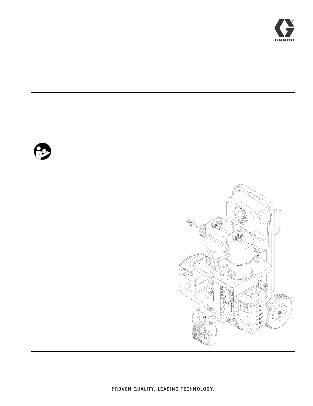
Operation
™
Xtreme Mix
Plural Component Mixer with stand. For professional use only.
Not approved for use in explosive atmospheres.
Important Safety Instructions
Read all warnings and instructions in this manual.
Save these instructions.
See page 3 for model information, including maximum working pressure and approvals.
United States Patent Number: 6,896,152
Chinese Patent Number: ZL02823545.2
Korean Patent Number: 10-0967987
European Patent Numbers: 126418, 145567, 1762138
309535L
ENG
Page 2

Related Documentation
Contents
Related Documentation . . . . . . . . . . . . . . . . . . . . . 2
Xtreme Mix Models . . . . . . . . . . . . . . . . . . . . . . . . . 3
Manual Conventions . . . . . . . . . . . . . . . . . . . . . . . . 4
Warnings . . . . . . . . . . . . . . . . . . . . . . . . . . . . . . . . . 5
Overview . . . . . . . . . . . . . . . . . . . . . . . . . . . . . . . . . . 8
Pressure Relief Procedure . . . . . . . . . . . . . . . . . . 10
Proper Lifting of Unit . . . . . . . . . . . . . . . . . . . . . . . 11
Setup . . . . . . . . . . . . . . . . . . . . . . . . . . . . . . . . . . . . 11
Flushing . . . . . . . . . . . . . . . . . . . . . . . . . . . . . . . . . 14
Priming . . . . . . . . . . . . . . . . . . . . . . . . . . . . . . . . . . 18
Pump Test . . . . . . . . . . . . . . . . . . . . . . . . . . . . . . . 20
Spraying . . . . . . . . . . . . . . . . . . . . . . . . . . . . . . . . . 22
Mix and Integration Tests . . . . . . . . . . . . . . . . . . . 23
Batch Dispense or Ratio Check . . . . . . . . . . . . . . 24
Pump Cycle Counter . . . . . . . . . . . . . . . . . . . . . . . 25
Circulation Setting . . . . . . . . . . . . . . . . . . . . . . . . . 25
Shutdown . . . . . . . . . . . . . . . . . . . . . . . . . . . . . . . . 25
Alarms . . . . . . . . . . . . . . . . . . . . . . . . . . . . . . . . . . . 26
Performance Charts . . . . . . . . . . . . . . . . . . . . . . . . 27
Technical Data . . . . . . . . . . . . . . . . . . . . . . . . . . . . 31
Graco Standard Warranty . . . . . . . . . . . . . . . . . . . 32
Graco Information . . . . . . . . . . . . . . . . . . . . . . . . . 32
Related Documentation
Component Manuals This manual available in following languages:
Manual Description
309518 Xtreme Mix Repair
311762 Xtreme Displacement Pump
309347 King Air Motor
or 309348 King Quiet Air Motor
312145 XTR Spray Gun
309524 VISCON HP Heater
309525 Heated Hose Kit
308981 Husky 716 Diaphragm Pump
309615 Heater Bracket Kit
309568 Remote Manifold Kit
310797 Remote Mix Manifold
310794 Remote Mix Proportioning Systems
310863 Feed and Flush Kits
309827 Air Supply Kits
Manual Language Manual Language
309535 English 309600 Swedish
309536 French 309601 Chinese
309537 Brazilian
Portuguese
309545 Spanish 309603 Japanese
309596 German 310754 Dutch
309597 Greek 310755 Norwegian
309598 Italian 310756 Danish
309599 Finnish
309602 Korean
Alarm Code Labels:
Part No. Languages
15B843 Chinese, Finnish, Portuguese, Greek, Swedish,
Italian
15B844 English, Spanish, French, German, Korean,
Japanese
2 309535L
Page 3
Xtreme Mix Models
Xtreme Mix Models
WARNING
Do not install equipment approved only for non-hazardous location in a hazardous area. Substitution of components may impair intrinsic safety. See page 5.
Approved for Non-hazardous Location
Xtreme
Mix
Part No. Series
233863 A 249274 45:1 King 4500 (31, 310)
233864 A 249275 56:1 King 5600 (38.6, 386)
233865 A 249276 68:1 King 6800 (46.9, 469)
233866 A 249277 80:1 King 7250 (50, 500)
233867 A 249278 45:1 Quiet King 4500 (31, 310)
233868 A 249279 56:1 Quiet King 5600 (38.6, 386)
233869 A 249280 68:1 Quiet King 6800 (46.9, 469)
233870 A 249281 80:1 Quiet King 7250 (50, 500)
*248842 A 249276 68:1 King
*Model 248842 is designed for remote feed pumps and a remote mix manifold. It does not include hoppers, mix
manifold, hose, or spray gun. Refer to manual 310794 for application layout.
Model 248842 is limited to 5000 psi (34.5 MPa, 345 bar) for use in “quick set” packages where heated hoses,
whip hoses, and spray accessories are limited to 5000 psi (34.5 MPa, 345 bar). If all your downstream components are rated for 7000 psi (48 MPa, 483 bar), you can replace the standard relief valve with relief valve
113498.
Pump
Part No.
Pump
Description
Remote Mix
Maximum Working
Pressure
psi (MPa, bar) Approvals
5000 (34.5, 345)
309535L 3
Page 4

Manual Conventions
Manual Conventions
WARNING
Hazard Symbol
Note
Additional helpful information.
WARNING: a potentially hazardous situation which, if
not avoided, could result in death or serious injury.
Warnings in the instructions usually include a symbol
indicating the hazard. Read the general Warnings
section for additional safety information.
CAUTION
CAUTION: a potentially hazardous situation which, if
not avoided, may result in property damage or
destruction of equipment.
Components A and B
IMPORTANT!
Material supplier s can vary in how they refer to plural
component materials.
Be aware that in this manual:
Component A refers to resin or major volume.
Component B refers to catalyst (curing agent) or minor
volume.
4 309535L
Page 5
Warnings
Warnings
The following general warnings are related to the safe setup, use, grounding, maintenance, and repair of this equipment. Additional more specific warnings may be found throughout the text of this manual where applicable.
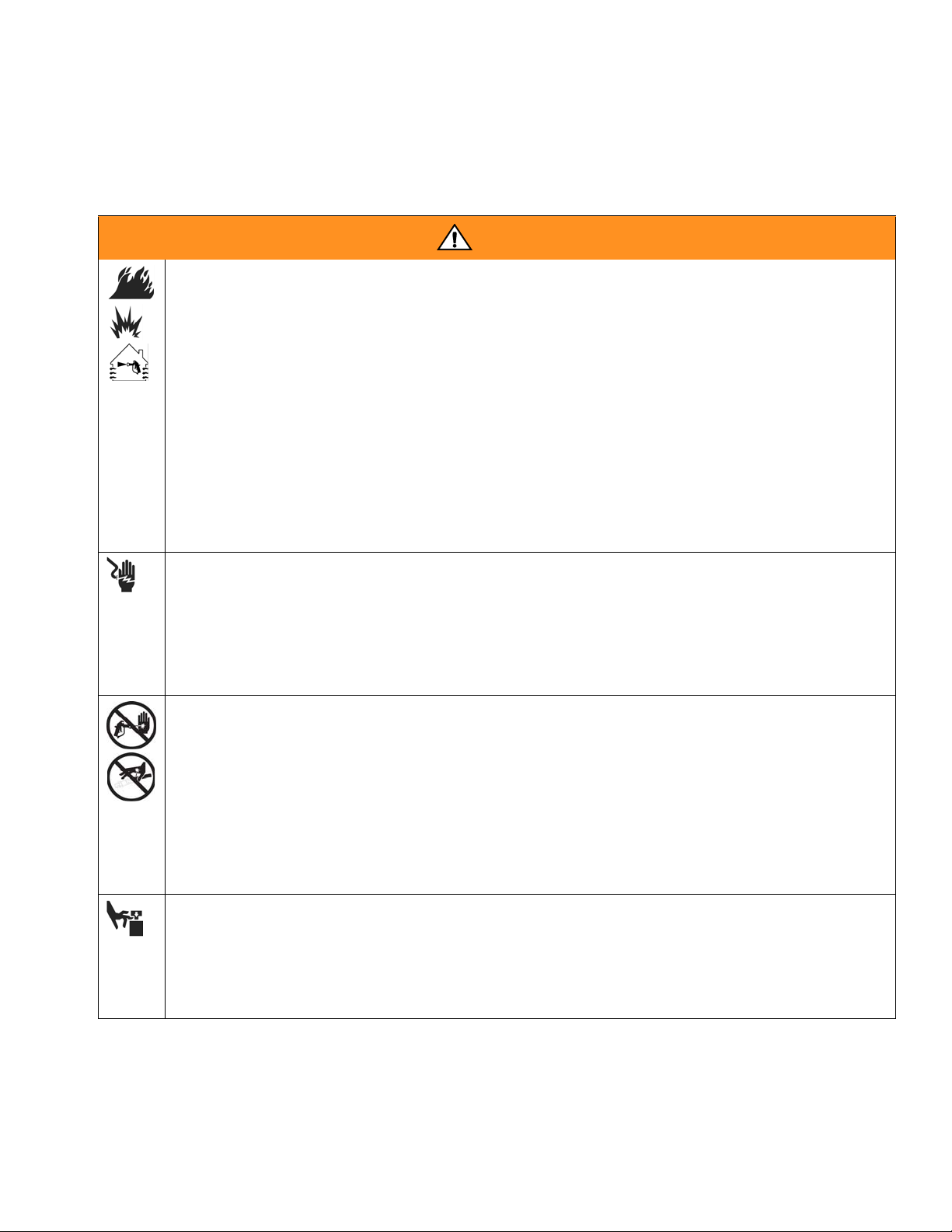
Warning
FIRE AND EXPLOSION HAZARD
Flammable fumes, such as solvent and paint fumes, in work area can ignite or explode. To help prevent
fire and explosion:
• Use equipment only in well ventilated area.
• Eliminate all ignition sources; such as pilot lights, cigarettes, portable electric lamps, and plastic drop
cloths (potential static arc).
• Keep work area free of debris, including solvent, rags and gasoline.
• Do not plug or unplug power cords, or turn power or light switches on or off when flammable fumes
are present.
• Ground equipment and conductive objects in work area. See Grounding instructions.
• Use only grounded hoses.
• Hold gun firmly to side of grounded pail when triggering into pail.
• If there is static sparking or you feel a shock, stop operation immediately. Do not use equipment
until you identify and correct the problem.
• Keep a fire extinguisher in the work area.
ELECTRIC SHOCK HAZARD
Improper grounding, setup, or usage of the system can cause electric shock.
• Turn off and disconnect power at main switch before disconnecting any cables and before servicing
equipment.
• Connect only to grounded power source.
• All electrical wiring must be done by a qualified electrician and comply with all local codes and regulations.
SKIN INJECTION HAZARD
High-pressure fluid from gun, hose leaks, or ruptured components will pierce skin. This may look like just
a cut, but it is a serious injury that can result in amputation. Get immediate surgical treatment.
• Do not point gun at anyone or at any part of the body.
• Do not put your hand over the spray tip.
• Do not stop or deflect leaks with your hand, body, glove, or rag.
• Do not spray without tip guard and trigger guard installed.
• Engage trigger lock when not spraying.
• Follow Pressure Relief Procedure in this manual, when you stop spraying and before cleaning,
checking, or servicing equipment.
MOVING PARTS HAZARD
Moving parts can pinch or amputate fingers and other body parts.
• Keep clear of moving parts.
• Do not operate equipment with protective guards or covers removed.
• Pressurized equipment can start without warning. Before checking, moving, or servicing equipment,
follow the Pressure Relief Procedure in this manual. Disconnect power or air supply.
309535L 5
Page 6
Warning
Warning
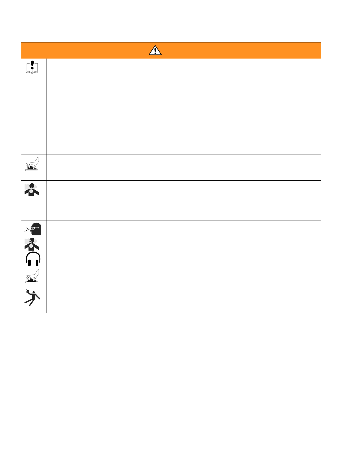
EQUIPMENT MISUSE HAZARD
Misuse can cause death or serious injury.
• Do not exceed the maximum working pressure or temperature rating of the lowest rated system com-
ponent. See Technical Data in all equipment manuals.
• Use fluids and solvents that are compatible with equipment wetted parts. See Technical Data in all
equipment manuals. Read fluid and solvent manufacturer’s warnings.
• Check equipment daily. Repair or replace worn or damaged parts immediately.
• Do not alter or modify equipment.
• For professional use only.
• Use equipment only for its intended purpose. Call your Graco distributor for information.
• Route hoses and cables away from traffic areas, sharp edges, moving parts, and hot surfaces.
• Do not kink or overbend hoses or use hoses to pull equipment.
• Comply with all applicable safety regulations.
BURN HAZARD
Equipment surfaces and fluid that’s heated can become very hot during operation. To avoid severe burns,
do not touch hot fluid or equipment. Wait until equipment/fluid has cooled completely.
TOXIC FLUID OR FUMES HAZARD
Toxic fluids or fumes can cause serious injury or death if splashed in the eyes or on skin, inhaled, or swallowed.
• Read MSDS’s to know the specific hazards of the fluids you are using.
• Store hazardous fluid in approved containers, and dispose of it according to applicable guidelines.
PERSONAL PROTECTIVE EQUIPMENT
You must wear appropriate protective equipment when operating, servicing, or when in the operating
area of the equipment to help protect you from serious injury, including eye injury, inhalation of toxic
fumes, burns, and hearing loss. This equipment includes but is not limited to:
• Protective eyewear
• Clothing and respirator as recommended by the fluid and solvent manufacturer
•Gloves
• Hearing protection
RECOIL HAZARD
Gun may recoil when triggered and cause you to fall and be seriously injured if you are not standing
securely.
6 309535L
Page 7

Warning
309535L 7
Page 8
Overview
B
A
Overview
Usage
The Xtreme Mix can mix most two-component epoxy
and urethane paints. Only Model 248842 is for use with
“quick-setting” paints (those with a pot life of less than
15 minutes). Other models cannot be used with such
paints without modification. Contact your distributor for
information.
The Xtreme Mix is operated with the User Interface, Air
Controls and Fluid Controls, described below and on
page 9. Refer to F
IG. 1 and FIG. 2.
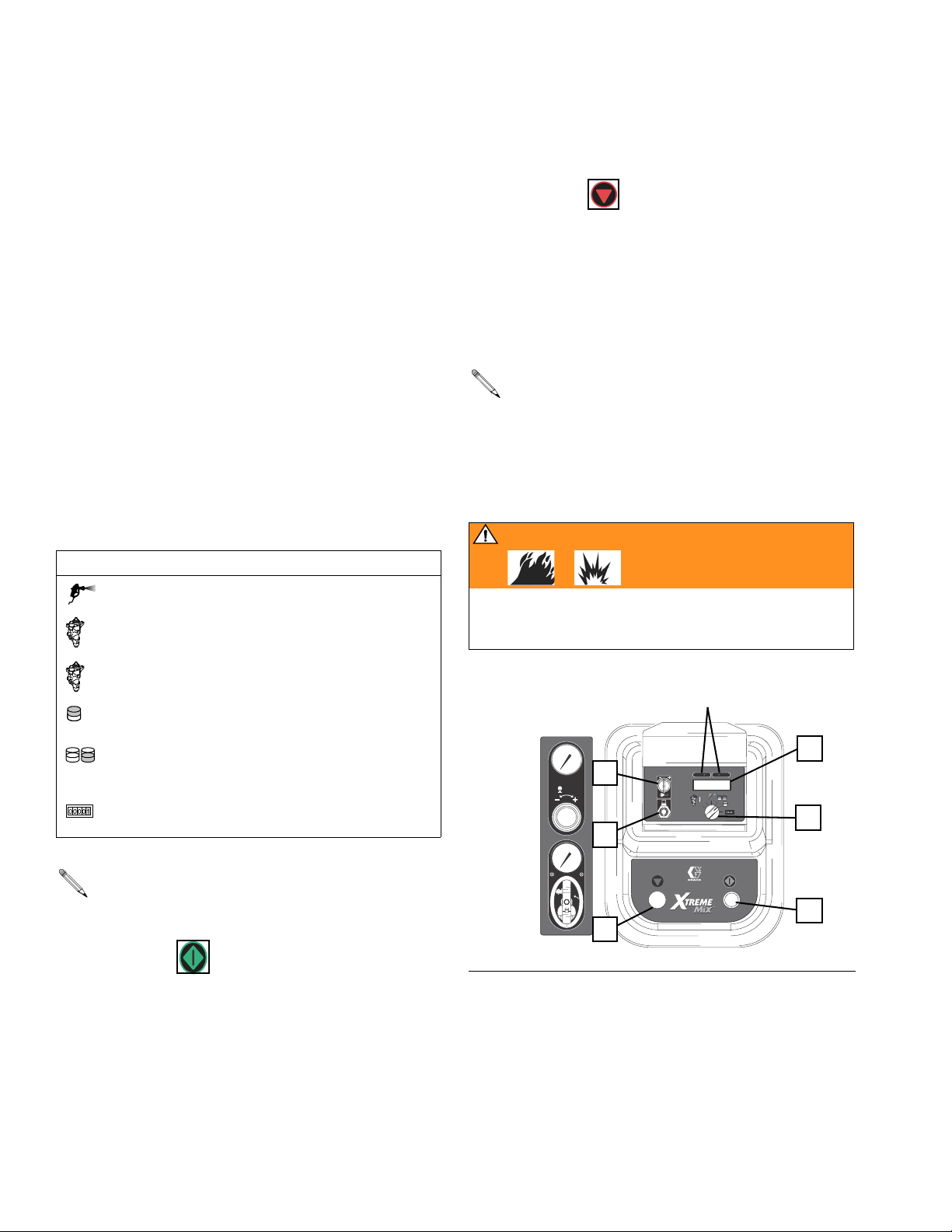
User Interface
The User Interface has 6 main interfaces.
1. Knob to select functions:
Icon Function
Spray: proportion and spray material
Run pump A: operate pump A independent
A
B
of pump B (priming, flushing) for 12 cycles
Run pump B: operate pump B independent
of pump A (priming, flushing) for 12 cycles
Batch Dispense: dispense proportioned
amounts of A and B
Pump Test: dispense predetermined
amount of A and B to verify pump operation
and metering
Cycle Counter: totalize A and B pump
cycles
3. Stop button to terminate functions
4. Key switch to change ratio or reset pump cycle
counter
5. Display (five-digits) to view:
•Ratio
• Alarm codes
• Pump cycles
The display includes an alarm code label in English. See page 2 to order additional languages.
6. Data port allows for connection to a PC serial port
to download cycle count, operation, ratio setting,
and error alarm data.
WARNING
The PC must be in a non-hazardous location and a
safety barrier must be installed between the PC and
Xtreme Mix unit. See Xtreme Mix software manual.
L
5
4
PSI
Bar
MPa
0
BA
1
6
PSI
Bar
When run independently, A and B light indicators
(L) will show which pump is running.
MPa
I
O
2
3
IG. 1
2. Start button to initiate functions
8 309535L
F
Page 9
Overview
B
A
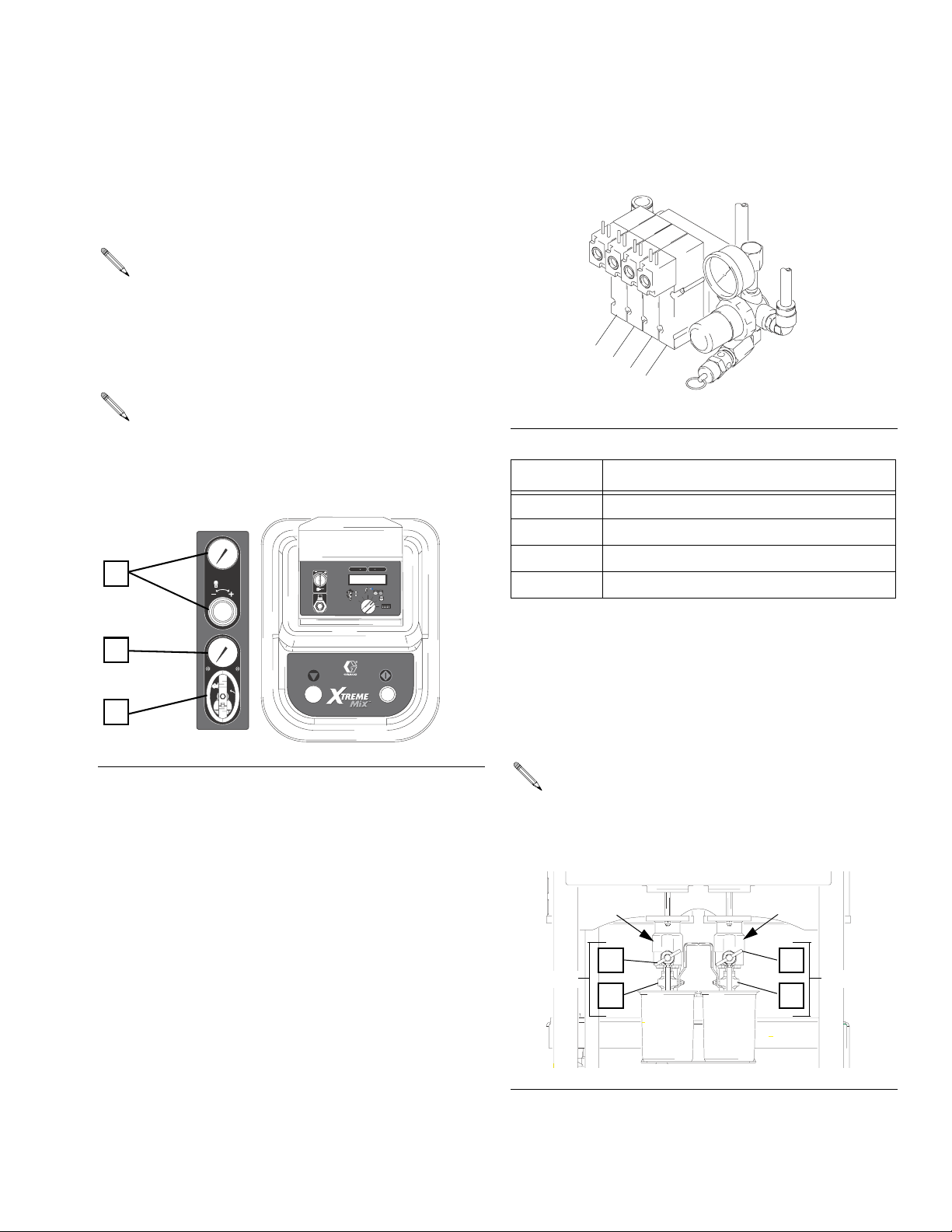
Air Controls
A. Main air shutoff valve (bleed-type) to shutoff all
air to Xtreme Mix (including controller power)
B. Supply air pressure gauge to monitor air pressure
to Xtreme Mix
A minimum air pressure supply of 50 psi (0.35
MPa, 3.5 bar) must be maintained for the Xtreme
Mix to operate properly.
C. Pump air pressure regulator with gauge to adjust
and monitor pump air pressure
Push in regulator knob to lock setting. Be careful
when pulling knob out to change setting as knob
is removable. To reinstall, push knob to snap into
place.
C
PSI
Bar
MPa
0
BA
Solenoid Module
There are 4 solenoids inside the controller.
1
2
3
4
FIG. 3
Solenoid ON/OFF for:
1 Metering valve A
2 Metering valve B
3 Pilot valve A - turns pump A ON/OFF
4 Pilot valve B - turns pump B ON/OFF
F
B
A
IG. 2
Fluid Controls
PSI
Bar
MPa
I
O
D. Sampling valves A and B to batch dispense or test
pumps
E. Shutoff valves A and B to shutoff fluid A or B from
entering the fluid manifold
There are 2 metering valves, one for fluid A (F1)
and one for fluid B (F2). The metering valves are
turned on and off by solenoids 1 and 2.
F1
D
A Side
E
F2
D
B Side
E
AB
F
IG. 4
ti2249a
309535L 9
Page 10
Pressure Relief Procedure
Pressure Relief Procedure
WARNING
Follow Pressure Relief Procedure when you stop
spraying and before cleaning, checking, servicing, or
transporting equipment. Read warnings, page 5.
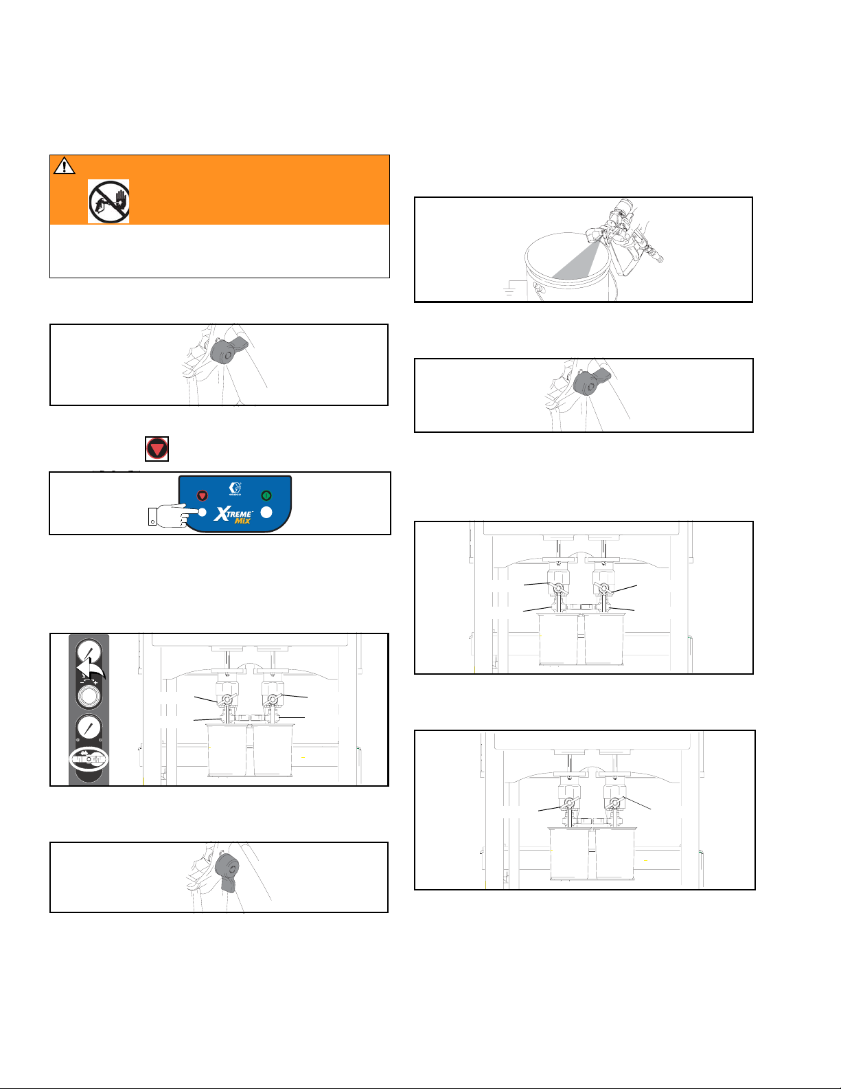
1. Engage trigger lock.
ti1949a
2. Press Stop .
SUPPLY AIR
PRESSURE
I
O
PLURAL COMPONENT PROPORTIONER
6. Hold a metal part of the gun firmly to a grounded
metal pail. Trigger gun to relieve pressure.
7. Engage trigger lock.
ti1949a
8. Place waste container under sampling valves, then
open valves A and B slowly to relieve pressure
between pump and metering valves.
3. Close main air shutoff valve on air supply line and on
unit. Turn off air regulator.
4. Close fluid sampling and shutoff valves A and B.
PSI
Bar
MPa
Close
Close
PSI
Bar
MPa
I
O
AB
Close
Close
5. Disengage trigger lock.
ti1950a
Open
Close
AB
9. Close sampling valve A and B.
Close
A
B
Open
Close
Close
10 309535L
Page 11

Proper Lifting of Unit
Proper Lifting of Unit
WARNING
Follow instructions below to avoid dropping or swinging unit or being struck by the cart handle, which can
cause serious injury or damage to equipment.
Either remove the cart handle or secure it to the cart
before lifting the unit. Connect a bridle swing, hooking
an end to each of the Xtreme Mix air motor rings. Hook
the center ring on a hoist. See F
Xtreme Mix unit; make sure it balances evenly.
IG. 5. Carefully lift the
1. Grounding: Connect Xtreme Mix ground wire clamp
(G) to a true earth ground.
G
ti2218a
2. Model 248842 Only: This model uses a remote mix
manifold, which is connected to the unit by at least
50 ft. (15 m) of individual fluid hoses. Refer to manuals 310794 and 310797 for typical setups.
All Other Models: The 50 ft. (15 m) fluid hose (W),
static mixer (X), whip hose (Y), and gun (Z) come
assembled. Note the order of connection.
CAUTION
Do not assemble static mixer (X) directly to fluid manifold. Install static mixer after first 50 ft. (15 m) of hose
to ensure material is completely mixed. Spraying
unmixed material could necessitate rework of part
sprayed.
ti2319a
F
IG. 5
Setup
WX Z Y
WARNING
Do not install equipment approved only for non-hazardous location in a hazardous area. Substitution of
components may impair intrinsic safety. Read warnings, page 5. Ground equipment as instructed below.
If connecting PC for data download, PC must be in
non-hazardous location and a safety barrier must be
installed. See Xtreme Mix software documentation.
309535L 11
Page 12

Setup
B
A
3. Connect the fluid hose (W) to the fluid manifold out-
let (J). Do not install gun spray tip yet.
J
4. Tighten all fittings on unit.
5. Fill pumps A and B packing nuts with throat seal liq-
uid (TSL) and torque to 25-30 ft-lb (34-41 N•m). Follow instructions in pump manual.
6. Fill metering valves A and B packing nuts (H) with
throat seal liquid (TSL) and tighten 1/4 turn after nut
contacts packings; about 145-155 in/lbs (16-18
N•m). Check packing nut tightness after first hour of
operation, again after 24 hours, then check as
needed (when TSL discolors or seeps over packing
nut). Also check tightness whenever unit is transported.
7. Connect air supply line to 3/4 npt(f) air filter inlet (F).
Air supply requirement: 110 psi (0.8 MPa, 8 bar)
maximum, 50 psi (0.35 MPa, 3.5 bar) minimum
Flow volume required: 60 scfm minimum; 250
scfm maximum
Model 248842 is designed to use Air Supply Kit
248827.
F
TI2218A
8. Turn off air regulator. Open main air shutoff valve.
When starting up, display will show “88888”, then
software revision, then current ratio.
PSI
Bar
MPa
0
BA
H
PSI
Bar
MPa
I
O
12 309535L
Page 13

Setup
B
A
9. Setup ratio.
a. Turn knob to spray .
b. Current ratio displays.
c. Turn key to +, hold for 1 second, then turn back
to neutral (vertical) to increase ratio by 0.1.
Turning key to + increases ratio by increments
of 0.1 until key is turned back to neutral (vice
versa when key is turned to –).
To decrease ratio, follow same pattern as
increasing, only turn key to –.
+–
0
BA
2.0:1
10.Flush and prime system. See pages 14 and 18. Run
Pump Test, page 20 to check ratio accuracy.
309535L 13
Page 14

Flushing
Flushing
There are times when you only want to flush the fluid
manifold, such as:
• breaks in spraying
• overnight shutdown
• end of potlife
In this manual, that procedure is referred to as Fluid
Manifold Flushing. You can flush the fluid manifold by
connecting either a:
• solvent pump to the fluid manifold or
• hose and solvent siphon tube to pump A
Other times, you need to flush the entire system:
• first time material is loaded into equipment*
• color change
•servicing
• shutting down equipment for more than 24 hours
• putting equipment into storage
* Some Full System Flushing steps are not necessary for
initial flushing, as no material has been loaded into the system yet.
Fluid Manifold Flushing
Model 248842 Only: Follow the flushing procedure
in the Remote Manifold manual 310797.
Using Solvent Pump
1. Press Stop to turn off proportioner. Follow Pres-
sure Relief Procedure, page 10. Engage trigger
lock. Remove spray tip.
ti1949a
2. Close sampling valves and fluid shutoff valves A and
B.
TI1948A
To flush the entire system, you first follow the Fluid
Manifold Flushing procedure, at right, then the Full
System Flushing procedure, page 16.
WARNING
Read warnings, pages 5-6.
• If your system includes heaters and heated
hose, turn them off and allow to cool before
flushing. Do not turn on heaters until fluid
lines are clear of solvent.
• Use the lowest possible pressure when flushing to avoid splashing.
• Before color change or shutdown for storage,
flush at a higher flow rate and for a longer
time.
• To only flush fluid manifold, see following procedure.
• A circulation setting is available. Consult your
distributor. Refer to page 25.
Close
Close
Close
Close
AB
3. Connect a shutoff valve (V) to the fluid manifold inlet
on the A side as shown below (valve shown closed).
Connect solvent pump line to the shutoff valve. Turn
on solvent pump and open solvent shutoff valve.
V
14 309535L
Page 15

Flushing
4. Adjust regulator to desired pressure; use lowest
pressure possible.
5. Disengage trigger lock and trigger gun into a
grounded pail. Flush out mixed material until clean
solvent dispenses. Engage trigger lock.
ti1950a
ti1953a
ti1949a
6. Shut off solvent pump and close solvent shutoff
valve.
Using Solvent Siphon Tube
1. Press Stop to turn off pumps. Follow Pressure
Relief Procedure, page 10. Engage trigger lock.
Remove spray tip.
ti1949a
TI1948A
2. Connect fluid hose with solvent siphone tube to
pump A 3-way ball valve. Put solvent siphon tube
into a grounded solvent pail.
7. Follow Pressure Relief Procedure, page 10.
Engage trigger lock.
ti1953a ti1949a
3. Turn pump A 3-way ball valve to open suction tube
line, as shown below. Arrow on handle shows direction of flow.
A
Suction Tube Line
4. Open main air shutoff valve. Open shutoff valve A.
Close sampling valves A and B.
PSI
Bar
MPa
Close
Open
PSI
Bar
MPa
I
O
AB
Close
Close
309535L 15
Page 16

Flushing
B
A
B
A
5. Turn knob to pump A . Press Start . Slowly
A
turn up air regulator until pump A starts.
BA
PSI
Bar
MPa
0
A
2. Place beakers under fluid sampling valves. Open
main air shutoff valve. Open fluid sampling valves A
and B.
PSI
Bar
MPa
Open
Open
PSI
Bar
MPa
I
O
6. Disengage trigger lock and trigger gun into a
grounded pail until clean solvent dispenses.
ti1950a
ti1953a
7. Engage trigger lock. Press Stop to turn off pro-
portioner.
8. Follow Pressure Relief Procedure, page 10.
Full System Flushing
1. Follow Pressure Relief Procedure, page 10.
Engage trigger lock. Turn off air regulator and close
main air shutoff valve. Remove spray tip and soak in
solvent.
Close
PSI
Bar
MPa
I
O
AB
Close
3. Turn up air regulator. Pump A and B reservoirs
empty, salvaging the material in separate, clean
containers.
4. Add solvent to A and B reservoirs.
5. Close sampling valves. Set air regulator to 50 psi
(345 kPa, 3.4 bar).
6. Turn knob to pump A . Press Start .
PSI
Bar
MPa
PSI
Bar
MPa
I
O
A
BA
0
A
PSI
Bar
MPa
When run independently (set to or ), the
A B
pump runs for 12 cycles, then stops.
Press Start and Stop as needed to clean.
PSI
Bar
MPa
I
O
ti1949a
7. Open sampling valve A. Pump material through
TI1948A
sampling valve A until clean, then press Stop .
If the pump does not start when you open the sampling valve, increase the air pressure by 10 psi (69
kPa, 0.7 bar) increments; to avoid splashing, do
not exceed 70 psi (483 kPa, 4.8 bar). If the pump
still does not start, the solvent may have caused
16 309535L
your packings to swell and it is recommended you
use Tuff Stack
™
Packing Kit 244900.
Page 17

8. Repeat steps 5 and 7, using pump B setting
B
A
B
A
B
A
B
and sampling valve B, then press Stop .
BA
PSI
Bar
MPa
0
B
Flushing
12.Trigger gun into grounded pail. Run pump until clean
solvent dispenses, then press Stop .
ti1953a
9. Remove fluid filter and soak in solvent. Replace filter
cap.
10.Close sampling valves A and B.
11.Turn knob back to pump A . Press Start .
PSI
Bar
MPa
PSI
Bar
MPa
I
O
A
BA
0
A
13.Repeat steps 11 and 12, using pump B setting,
B
then press Stop .
BA
PSI
Bar
MPa
0
B
14.Follow Pressure Relief Procedure, page 10, and
remove gun from hose. See gun manual to further
clean gun.
15.Clean hoppers as needed. Empty out solvent.
Some materials require additional cleaning. You
may need to recirculate solvent through the system or disassemble the hopper, 3-way valve, and
strainer to clean them.
309535L 17
Page 18

Priming
B
A
Priming
WARNING
Wear gloves if fluid temperature exceeds 110° F (43°
C).
Do not install the gun spray tip yet. Use the lowest
possible pressure to prime to avoid splashing.
1. Fill A and B reservoirs (R) with proper materials.
R
ti2318a
3. Turn off air regulator. Close fluid shutoff valves A and
B.
PSI
Bar
MPa
Close
PSI
Bar
MPa
I
O
AB
Close
4. Place a container under each sampling valve. Open
sampling valve A slowly.
Open
AB
AB
2. Turn both 3-way ball valves to open reservoir lines
as shown below. Arrow on handle shows direction of
flow.
A
B
ti2320a
When run independently (set to or ), the
A B
pump runs for 12 cycles, then stops.
Press Start and Stop as needed to prime.
Monitor containers to avoid overflowing.
5. Turn knob to pump A . Press Start . Turn up
A
air regulator slowly until pump A starts.
BA
PSI
Bar
MPa
PSI
Bar
MPa
I
O
0
A
18 309535L
Page 19

Priming
B
A
6. When side A is primed, turn off air regulator. Close
sampling valve A. Open sampling valve B slowly.
PSI
Bar
MPa
Close
PSI
Bar
MPa
I
O
AB
Open
7. Turn knob to pump B . Press Start . Turn up
B
air regulator slowly until pump B starts.
BA
PSI
Bar
MPa
0
B
PSI
Bar
MPa
I
O
8. When side B is primed, Stop and close sam-
pling valve B.
Close
AB
309535L 19
Page 20

Pump Test
B
A
B
A
B
A
Pump Test
Follow this procedure the first time system is operated
(after flushing and priming) and whenever you need to
check whether pumps are on ratio.
The following table shows the volume dispensed during
the pump test, based on pump ratio. Dispense into a
container with adequate graduations.
Pump Volume Dispensed
45:1 750 cc
56:1 660 cc
68:1 540 cc
80:1 435 cc
For accurate ratios, pump lowers must be same
size on both sides.
1. Turn knob to pump test . Turn off air regulator.
Open main air shutoff valve. Adjust air pressure to
50 psi (0.35 MPa, 3.5 bar).
c. Press Start . Pump A light comes on.
d. Slowly open and adjust sampling valve A to
achieve desired flow. The pump stops automatically when dispense is complete. Pump A light
turns off, Pump B light comes on.
PSI
Bar
MPa
I
O
d.
Open
A
3. Close sampling valve A.
c.
BA
PSI
Bar
MPa
PSI
Bar
MPa
I
O
0
2. Dispense fluid A:
a. Close fluid shutoff valves and sampling valves A
and B.
b. Place a clean 1 quart (1000 cc) container under
sampling valve A.
a. a.
Close
b.
A
Close
Close
A
4. Dispense fluid B as follows:
a. Place a clean 1 quart (1000 cc) container under
sampling valve B.
b. Slowly open and adjust sampling valve B to
achieve desired flow. The pump stops automatically when dispense is complete. Pump B light
turns off.
Open
b.
B
a.
20 309535L
Page 21

Pump Test
5. Close sampling valve B.
6. Compare fluid amounts in the containers; they
should be equal. Repeat test if fluids are not equal.
If problem persists, see Troubleshooting in Xtreme
Mix Repair Manual.
Close
B
309535L 21
Page 22

Spraying
B
A
B
A
Spraying
WARNING
Wear gloves if fluid temperature exceeds 110° F (43°
C).
1. If heaters are used, turn them on. Operate heaters
as instructed in their manuals.
2. Close sampling valves A and B. Open shutoff valves
A and B.
Close
Open
AB
Close
Open
ti2249a
5. Engage trigger lock. Press Stop .
BA
PSI
Bar
MPa
PSI
Bar
MPa
I
O
0
ti1949a
6. Follow Pressure Relief Procedure, page 10.
7. Engage trigger lock. Install tip on gun.
ti1949a
3. Turn knob to spray . Press Start .
BA
PSI
Bar
MPa
PSI
Bar
MPa
I
O
0
4. Trigger gun into a pail and slowly increase air regula-
tor pressure until pump is running and clean material
is dispensed.
PSI
Bar
MPa
PSI
Bar
MPa
I
O
ti1953a
8. Adjust air regulator to the necessary spraying pres-
sure and apply the coating. Refer to Mix and Integration Tests, page 23.
9. Follow Fluid Manifold Flushing, page 14, or Shut-
down, page 25, when you are done spraying or
before potlife expires.
Mixed material potlife or working time
decreases with increased temperature.
22 309535L
Page 23

Mix and Integration Tests
Mix and Integration Tests
Use the following tests to check for proper mix and integration.
Butterfly Test
WARNING
Follow Pressure Relief Procedure, page 10, before
removing spray tip. Read warnings, page 5.
At low pressure, normal flow rate, and without a spray tip
installed, dispense a 1/2” (12.7 mm) bead of material
onto foil until multiple changeovers of each pump have
occurred. Place a second sheet of foil over the first then
peel it back and look for unmixed material (appears marble-like).
Curing Test
Spray a single continuous pattern on foil at typical pressure setting, flow rate, and tip size until multiple changeovers of each pump have occurred. Trigger and
de-trigger at typical intervals for the application. Do not
overlap or cross over your spray pattern.
Check curing at various time intervals, listed on the
material data sheet. For example, check for dry to touch
by running your finger along the test pattern’s entire
length at the time listed on the data sheet.
Appearance Test
Spray material onto metal substrate. Look for variations
in color, gloss, or texture that may indicate improperly
catalyzed material.
309535L 23
Page 24

Batch Dispense or Ratio Check
B
A
B
A
B
A
Batch Dispense or
Ratio Check
Batch dispense is always 1 liter of total volume,
regardless of ratio setting.
Follow this procedure to dispense a batch (into one container) or verify a ratio setting (use separate container
for fluid A and B). Dispense into a container with graduations no greater that 5% of each component.
1. Turn knob to batch dispense . Turn off air regula-
tor. Open main air shutoff valve. Adjust air pressure
to 50 psi (0.35 MPa, 3.5 bar).
BA
PSI
Bar
MPa
0
d. Slowly open and adjust sampling valve A to
achieve desired flow. The pump stops automatically when dispense is complete. Pump A light
turns off, Pump B light comes on.
PSI
Bar
MPa
I
O
d.
Open
A
3. Close sampling valve A.
c.
PSI
Bar
MPa
I
O
2. Dispense fluid A:
a. Close fluid shutoff valves and sampling valves A
and B.
b. Place a clean 1 quart (1000 cc) container under
sampling valve A.
a. a.
Close
b.
c. Press Start . Pump A light comes on.
A
Close
Close
A
4. Dispense fluid B as follows:
a. Batch dispense: move the 1 quart (1000 cc)
container under sampling valve B.
Ratio check: place clean 1 quart (1000 cc) container under sampling valve B.
b. Slowly open and adjust sampling valve B to
achieve desired flow. The pump stops automatically when dispense is complete. Pump B light
turns off.
Open
B
b.
a.
5. Batch dispense: stir material until mixed.
24 309535L
Ratio check: compare A and B fluid dispense.
Page 25

Pump Cycle Counter
B
A
Pump Cycle Counter
To display total A and B pump cycles since the last reset,
turn knob to cycle counter .
To reset the cycle counter to 0, turn the key to – (or 0)
while knob is set to cycle counter .
Reset
–
0
0
SETUP KEY
DATA PORT
VALVE
A
VALVE
BA
B
Circulation Setting
Fluid can be circulated up to the mix manifold. You can
only circulate one fluid component at a time. Additional
fluid hardware is required; consult your distributor.
To set the Xtreme Mix to circulate:
5. Depending on the ratio selected, the following will
occur:
• 1.0:1 - Air motor pilot valve A and metering
valve A open to run pump A.
• 0.0:1 - Air motor pilot valve B and metering
valve B open to run pump B.
To terminate circulation, press Stop .
To begin circulating again, press Start .
To begin spraying, reset to desired ratio and adjust
pump to spray pressure.
Shutdown
Follow this procedure before prolonged shutdown or
servicing equipment.
1. Follow Pressure Relief Procedure, page 10.
Engage trigger lock, turn off air regulator, and close
main air shutoff valve. Remove spray tip.
1. Decrease the pump air pressure supply to the mini-
mum required to maintain the desired circulation volume.
2. Turn knob to spray .
3. To circulate fluid A, set ratio to 1.0:0, which is the
lowest ratio setting
To circulate fluid B, set ratio to 0.0:1, which is the
second lowest ratio setting
See page 13 for instructions on setting ratio.
4. Press Start .
BA
PSI
Bar
MPa
PSI
Bar
MPa
I
O
0
PSI
Bar
MPa
PSI
Bar
MPa
I
O
ti1949a
2. Follow Flushing, page 14.
3. Follow Pressure Relief Procedure, page 10.
Engage trigger lock.
4. Before prolonged shutdown: cap fluid outlets to
keep solvent in the lines. Fill pump A and B packing
nuts with throat seal liquid (TSL); follow instructions
in pump manual.
TI1948A
309535L 25
Page 26

Alarms
Alarms
* Indicates error where audible alarm sounds once briefly.
** Indicates error where audible alarm sound pulses.
• An alarm condition will shutdown equipment.
• A chirping sound every 60 seconds indicates
the unit is set for circulation (page 25).
• See Xtreme Mix Repair manual for troubleshooting and repair.
Code Alarm Active Problem Cause
Startup Errors
01 Sensor Error A* Always No signal from pump A sensor Loose cable, failed sensor or cable
02 Sensor Error B* Always No signal from pump B sensor Loose cable, failed sensor or cable
03 Controller Error* Always Loss of communication between main
and display boards
Operating Errors
04 Pump Runaway A** Spray
05 Pump Runaway B**
06 Pump Error A** Spray
07 Pump Error B**
08 Sensor Code Error Always Software boot, sensor values reverted to
09 Metering Error A** Spray A dose too great Metering valve A leak
10 Metering Error B** Spray B dose too great Metering valve B leak
Te st
Batch
Te st
Batch
Pump running too fast
This alarm is not active when
pumps are run independently.
Pump does not stall after top change
over
Pump cavitating excessively
default
Loose cable, failed board
Empty fluid reservoir(s)
Clogged fluid filter
Hose rupture after mix manifold
Sampling valve open too far
Excessive cavitation
Foot valve leak
Air in lines caused by loose fitting or
use of agitator
Empty fluid reservoir(s)
Sensor value data corrupt; board
needs replacement and /or recalibration
Empty B fluid reservoir
Empty A fluid reservoir
11 Sensor Reading Low A* Always Pump stroke travels beyond sensor
12 Sensor Reading Low B*
13 Sensor Reading High A* Always Pump stroke travels beyond sensor
14 Sensor Reading High B*
range at bottom change over
range at top change over
Sensor or bracket loose
Sensor magnet dirty
Sensor or bracket loose
Sensor magnet dirty
Testing Error
15 Piston packing/ball A* Test Pump does not completely stall in up
16 Piston packing/ball B*
17 Inlet Ball A* Test Pump does not completely stall in down18 Inlet Ball B*
19 Metering Valve A* Test Pump does not completely stall in both
20 Metering Valve B*
26 309535L
stroke
stroke
up and down strokes
Piston packing or ball check failure
Foot valve ball check failure
Throat packing or metering valve fail-
ure
Page 27

Performance Charts
45:1 King Pump
Pressure
psi (MPa, bar)
5000
(34, 345)
4500
(31, 310)
4000
(28, 276)
3500
(24, 241)
Performance Charts
100 psi (7 MPa, 7 bar)
3000
(21, 207)
2500
(17, 172)
2000
(14, 138)
1500
(10, 103)
1000
(7, 69)
500
(3.4, 34)
70 psi (483 kPa, 4.8bar)
40 psi (276 kPa, 2.8bar)
0
0123 45
100 psi (7 MPa, 7 bar), 1:1 ratio
70 psi (483 kPa, 4.8bar), 1:1 ratio
40 psi (276 kPa, 2.8 bar),1:1 ratio
(3.8) (11.4) (15.1) (18.9)(7.6)
4:1 ratio
10:1 ratio
4:1 ratio
10:1 ratio
4:1 ratio
10:1 ratio
Fluid Flow
GPM (liter/min.)
309535L 27
Page 28

Performance Charts
56:1 King Pump
Pressure
psi (MPa, bar)
6000
(41, 414)
5500
(38, 379)
5000
(34, 345)
4500
(31, 310)
4000
(28, 276)
3500
(24, 241)
3000
(21, 207)
2500
(17, 172)
2000
(14, 138)
1500
(10, 103)
1000
(7, 69)
500
(3.4, 34)
0
0123 45
100 psi (7 MPa, 7 bar), 1:1 ratio
70 psi (483 kPa, 4.8bar), 1:1 ratio
40 psi (276 kPa, 2.8 bar),1:1 ratio
100 psi (7 MPa, 7 bar)
70 psi (483 kPa, 4.8bar)
40 psi (276 kPa, 2.8bar)
(3.8) (11.4) (15.1) (18.9)
(3.8)
Fluid Flow
4:1 ratio
10:1 ratio
4:1 ratio
10:1 ratio
4:1 ratio
10:1 ratio
GPM (liter/min.)
28 309535L
Page 29

68:1 King Pump
Pressure
psi (MPa, bar)
7000
(48, 483)
6500
(45, 448)
6000
(41, 414)
5500
(38, 379)
5000
(34, 345)
4500
(31, 310)
4000
(28, 276)
3500
(24, 241)
3000
(21, 207)
2500
(17, 172)
2000
(14, 138)
1500
(10, 103)
1000
(7, 69)
500
(3.4, 34)
0
0123 45
100 psi (7 MPa, 7 bar), 1:1 ratio
70 psi (483 kPa, 4.8bar), 1:1 ratio
40 psi (276 kPa, 2.8 bar),1:1 ratio
100 psi (7 MPa, 7 bar)
70 psi (483 kPa, 4.8bar)
40 psi (276 kPa, 2.8bar)
(3.8) (11.4) (15.1) (18.9)(7.6)
4:1 ratio
10:1 ratio
4:1 ratio
10:1 ratio
4:1 ratio
10:1 ratio
Performance Charts
Fluid Flow
GPM (liter/min.)
309535L 29
Page 30

Performance Charts
80:1 King Pump
Pressure
psi (MPa, bar)
6000
(41, 414)
5500
(38, 379)
5000
(34, 345)
4500
(31, 310)
4000
(28, 276)
3500
(24, 241)
3000
(21, 207)
2500
(17, 172)
(17, 172)
2000
(14, 138)
1500
(10, 103)
1000
(7, 69)
500
(3.4, 34)
0
0123 45
70 psi (483 kPa, 4.8bar), 1:1 ratio
40 psi (276 kPa, 2.8 bar),1:1 ratio
70 psi (483 kPa, 4.8bar)
40 psi (276 kPa, 2.8bar)
(3.8) (11.4) (15.1) (18.9)(7.6)
4:1 ratio
10:1 ratio
4:1 ratio
10:1 ratio
Fluid Flow
GPM (liter/min.)
30 309535L
Page 31

Technical Data
Technical Data
Mix ratio range . . . . . . . . . . . . . . . . . . . . . . . . . . . . . . . . . 0.0:1-10:1 (in 0.1 increments)
Ratio tolerance range . . . . . . . . . . . . . . . . . . . . . . . . . . . . +/- 5%
Flow rates
Minimum. . . . . . . . . . . . . . . . . . . . . . . . . . . . . . . . . . . 1 qt./min. (0.95 liter/min.)*
Maximum . . . . . . . . . . . . . . . . . . . . . . . . . . . . . . . . . . 3 gal./min. (11.4 liter/min.)
Fluid viscosity range . . . . . . . . . . . . . . . . . . . . . . . . . . . . . 200-20,000 cps (heavier viscosities can be mixed with use
of optional heaters, heated hoses, and hardware)
Fluid filtration . . . . . . . . . . . . . . . . . . . . . . . . . . . . . . . . . . 60 mesh, (238 micron) standard on pump outlets (filter
assembly not included on models 248831, 248832,
248833, and 248834)
Air inlet
Model 248842. . . . . . . . . . . . . . . . . . . . . . . . . . . . . . .
All Other Models. . . . . . . . . . . . . . . . . . . . . . . . . . . . .
Model 248842 Fluid inlet. . . . . . . . . . . . . . . . . . . . . . . . . . 3/4 npsm union in 1” npt(f) ball valve
Maximum fluid working pressure
45:1 . . . . . . . . . . . . . . . . . . . . . . . . . . . . . . . . . . . . . . 4500 psi (31 MPa, 310 bar)
56:1 . . . . . . . . . . . . . . . . . . . . . . . . . . . . . . . . . . . . . . 5600 psi (38.6 MPa, 386 bar)
68:1 . . . . . . . . . . . . . . . . . . . . . . . . . . . . . . . . . . . . . . 6800 psi (46.9 MPa, 469 bar)
68:1 Model 248842 only . . . . . . . . . . . . . . . . . . . . . . . 5000 psi (34.5 MPa, 345 bar)
80:1 . . . . . . . . . . . . . . . . . . . . . . . . . . . . . . . . . . . . . . 7250 psi (50 MPa, 500 bar)
Air supply pressure range . . . . . . . . . . . . . . . . . . . . . . . . . 50-110 psi (345-800 kPa, 3.5-8 bar)
Model 248842: Maximum fluid feed pressure. . . . . . . . . . 500 psi (3.5 MPa, 35 bar)
Maximum air consumption at 100 psi (0.7 MPa, 7 bar) in cfm (m
45:1 . . . . . . . . . . . . . . . . . . . . . . . . . . . . . . . . . . . . . . 110 (3.1)
56:1 . . . . . . . . . . . . . . . . . . . . . . . . . . . . . . . . . . . . . . 125 (3.5)
68:1 . . . . . . . . . . . . . . . . . . . . . . . . . . . . . . . . . . . . . . 155 (4.4)
80:1 . . . . . . . . . . . . . . . . . . . . . . . . . . . . . . . . . . . . . . 180 (5.1)
Ambient temperature range
Operating . . . . . . . . . . . . . . . . . . . . . . . . . . . . . . . . . . 32-130° F (0-54° C)
Storage. . . . . . . . . . . . . . . . . . . . . . . . . . . . . . . . . . . . 30-160° F (–1-71° C)
Environmental Conditions Rating . . . . . . . . . . . . . . . . . . . Indoor/outdoor use
Sound pressure . . . . . . . . . . . . . . . . . . . . . . . . . . . . . . . . 98 dBA at 100 psi (0.7 MPa, 7 bar)
Wetted parts
Suction tubes (if used) . . . . . . . . . . . . . . . . . . . . . . . . aluminum
Pumps . . . . . . . . . . . . . . . . . . . . . . . . . . . . . . . . . . . . carbon steel, alloy steel, 303, 440 & 17-4ph grades stain-
Metering Valves . . . . . . . . . . . . . . . . . . . . . . . . . . . . . carbon steel, zinc plating, carbide, polyethylene, leather
Manifold . . . . . . . . . . . . . . . . . . . . . . . . . . . . . . . . . . . carbon steel, zinc plating, carbide, 302 stainless steel
Mixer. . . . . . . . . . . . . . . . . . . . . . . . . . . . . . . . . . . . . . stainless steel
Spray gun . . . . . . . . . . . . . . . . . . . . . . . . . . . . . . . . . . See gun manual
PC Communications . . . . . . . . . . . . . . . . . . . . . . . . . . . . . RS-232
Dimensions
Cart model (width x height x diameter) . . . . . . . . . . . 33” wide x 64.53” high x 44.5” deep
Weight (cart, without hose and gun). . . . . . . . . . . . . . 625 lbs. (285 kg)
* Minimum flow rate is dependent on the material being sprayed and mixing capability. Test your material for specific flow rate.
3/4 npt(m)
3/4 npt(f)
3
/min.)
Altitude up to 4000 meters
Maximum relative humidity to 99% up to 54° C
Pollution degree (11)
Installation category (2)
less steel, zinc and nickel plating, ductile iron, tungsten
carbide, PTFE, leather
(83.8 x 163.9 x 113 cm)
309535L 31
Page 32

Graco Standard Warranty
Graco warrants all equipment referenced in this document which is manufactured by Graco and bearing its name to be free from defects in
material and workmanship on the date of sale to the original purchaser for use. With the exception of any special, extended, or limited warranty
published by Graco, Graco will, for a period of twelve months from the date of sale, repair or replace any part of the equipment determined by
Graco to be defective. This warranty applies only when the equipment is installed, operated and maintained in accordance with Graco’s written
recommendations.
This warranty does not cover, and Graco shall not be liable for general wear and tear, or any malfunction, damage or wear caused by faulty
installation, misapplication, abrasion, corrosion, inadequate or improper maintenance, negligence, accident, tampering, or substitution of
non-Graco component parts. Nor shall Graco be liable for malfunction, damage or wear caused by the incompatibility of Graco equipment with
structures, accessories, equipment or materials not supplied by Graco, or the improper design, manufacture, installation, operation or
maintenance of structures, accessories, equipment or materials not supplied by Graco.
This warranty is conditioned upon the prepaid return of the equipment claimed to be defective to an authorized Graco distributor for verification of
the claimed defect. If the claimed defect is verified, Graco will repair or replace free of charge any defective parts. The equipment will be returned
to the original purchaser transportation prepaid. If inspection of the equipment does not disclose any defect in material or workmanship, repairs will
be made at a reasonable charge, which charges may include the costs of parts, labor, and transportation.
THIS WARRANTY IS EXCLUSIVE, AND IS IN LIEU OF ANY OTHER WARRANTIES, EXPRESS OR IMPLIED, INCLUDING BUT NOT LIMITED
TO WARRANTY OF MERCHANTABILITY OR WARRANTY OF FITNESS FOR A PARTICULAR PURPOSE.
Graco’s sole obligation and buyer’s sole remedy for any breach of warranty shall be as set forth above. The buyer agrees that no other remedy
(including, but not limited to, incidental or consequential damages for lost profits, lost sales, injury to person or property, or any other incidental or
consequential loss) shall be available. Any action for breach of warranty must be brought within two (2) years of the date of sale.
GRACO MAKES NO WARRANTY, AND DISCLAIMS ALL IMPLIED WARRANTIES OF MERCHANTABILITY AND FITNESS FOR A
PARTICULAR PURPOSE, IN CONNECTION WITH ACCESSORIES, EQUIPMENT, MATERIALS OR COMPONENTS SOLD BUT NOT
MANUFACTURED BY GRACO. These items sold, but not manufactured by Graco (such as electric motors, switches, hose, etc.), are subject to
the warranty, if any, of their manufacturer. Graco will provide purchaser with reasonable assistance in making any claim for breach of these
warranties.
In no event will Graco be liable for indirect, incidental, special or consequential damages resulting from Graco supplying equipment hereunder, or
the furnishing, performance, or use of any products or other goods sold hereto, whether due to a breach of contract, breach of warranty, the
negligence of Graco, or otherwise.
FOR GRACO CANADA CUSTOMERS
The Parties acknowledge that they have required that the present document, as well as all documents, notices and legal proceedings entered into,
given or instituted pursuant hereto or relating directly or indirectly hereto, be drawn up in English. Les parties reconnaissent avoir convenu que la
rédaction du présente document sera en Anglais, ainsi que tous documents, avis et procédures judiciaires exécutés, donnés ou intentés, à la suite
de ou en rapport, directement ou indirectement, avec les procédures concernées.
Graco Information
TO PLACE AN ORDER, contact your Graco distributor or call to identify the nearest distributor.
Phone: 612-623-6921 or Toll Free: 1-800-328-0211, Fax: 612-378-3505
All written and visual data contained in this document reflects the latest product information available at the time of publication.
Graco reserves the right to make changes at any time without notice.
Original Instructions. This manual contains English. MM 309535
Graco Headquarters: Minneapolis
International Offices: Belgium, China, Japan, Korea
GRACO INC. P.O. BOX 1441 MINNEAPOLIS, MN 55440-1441
Copyright 2002, Graco Inc. is registered to ISO 9001
www.graco.com
Revised 01/2011
 Loading...