

Page 1

Instructions
Water-Jacket
Heated Hose Kit
309525G
Part No. 245866
Includes parts needed to assemble heated hose system. Heated hose assembly and VISCON HP heater must be
ordered separately.
See Technical Data on page 14 for Maximum Working Pressure and Temperature Rating information.
Important Safety Instructions
Read all warnings and instructions in this
manual. Save these instructions.
EN
II2G
Page 2
Contents
Manual Conventions
Manual Conventions ........................2
Heated Hose Components ...................4
Installation ................................ 7
Operation ................................ 10
Maintenance ..............................11
Troubleshooting ..........................11
Related Manuals ...........................11
Parts ....................................12
Technical Data ............................14
Heated Hose Replacement Parts .............15
Graco Standard Warranty ...................16
Graco Information .........................16
Manual Conventions
Warning Caution
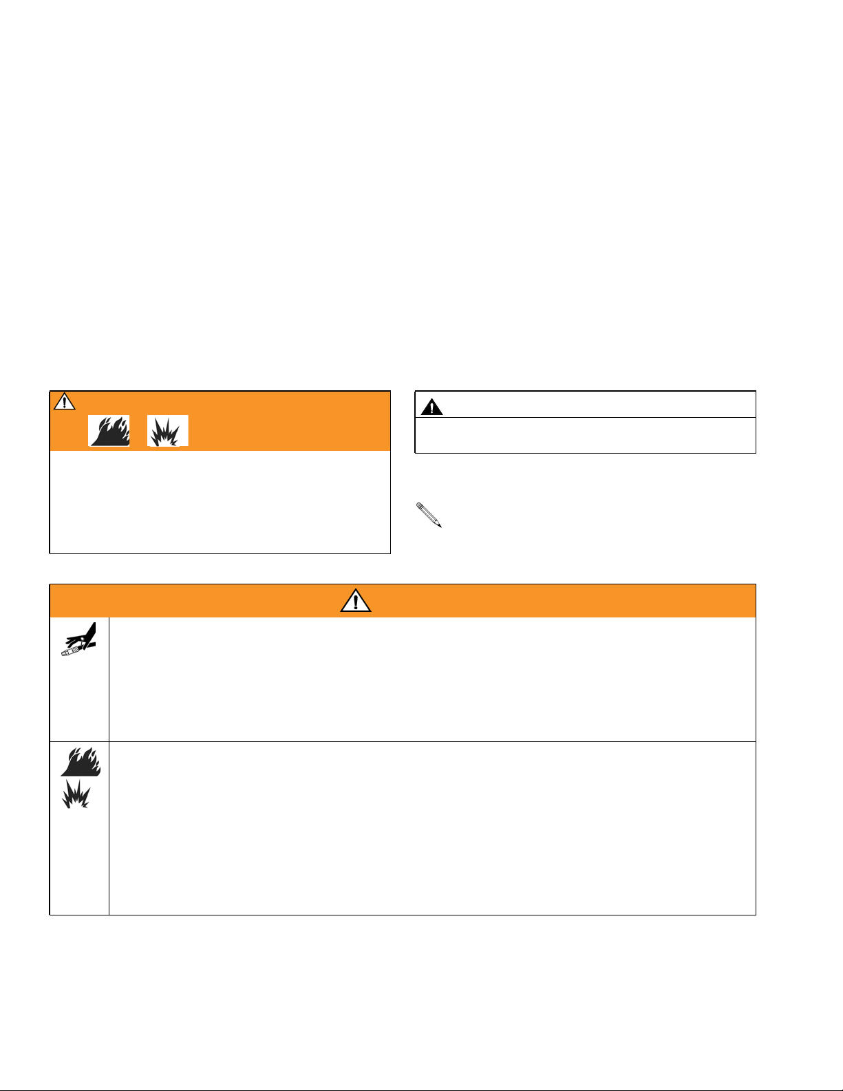
WARNING
A warning alerts you to possible serious injury or
death if you do not follow instructions.
Symbols, such as fire and explosion (shown), alert you
to a specific hazard and direct you to read the indicated hazard warnings (below).
CAUTION
A caution alerts you to possible equipment damage or
destruction if you do not follow instructions.
Note
A note indicates additional helpful information.
WARNING
SKIN INJECTION HAZARD
High-pressure fluid from gun, hose leaks, or ruptured components will pierce skin. This may look like just
a cut, but it is a serious injury that can result in amputation. Get immediate surgical treatment.
• Do not stop or deflect leaks with your hand, body, glove, or rag.
• Tighten all fluid connections before operating the equipment.
• Check hoses, tubes, and couplings daily. Replace worn or damaged parts immediately. High pressure hose cannot be recoupled; replace the entire hose.
FIRE AND EXPLOSION HAZARD
• Solvent and paint fumes in work area can ignite or explode. To help prevent fire and explosion:
• Use equipment only in well ventilated area.
• Eliminate all ignition sources, such as pilot lights, cigarettes and plastic drop cloths (potential static
arc).
• Do not plug or unplug power cords or turn lights on or off when flammable fumes are present.
• Keep the work area free of debris, including solvent, rags, and gasoline.
• Ground equipment and conductive objects.
• If there is static sparking or you feel an electric shock, stop operation immediately. Do not use
equipment until you identify and correct the problem.
2 309525G
Page 3

Warning
WARNING
ELECTRIC SHOCK HAZARD
Improper grounding, wiring, or usage of the system can cause electric shock.
• All electrical wiring must be done by a qualified electrician and comply with all local codes and regulations.
• Connect only to grounded power source.
• Turn off and disconnect power at the main switch before disconnecting any cables and before servicing equipment.
EQUIPMENT MISUSE HAZARD
Misuse can cause serious injury or death.
• For professional use only.
• Use equipment only for its intended purpose. Call your Graco distributor for information.
• Read manuals, warnings, tags, and labels before operating equipment. Follow instructions.
• Check equipment daily. Repair or replace worn or damaged parts immediately.
• Do not alter or modify equipment. Use only Graco parts and accessories.
• Do not exceed the maximum working pressure or temperature rating of the lowest rated system
component. See page 14 and the Technical Data for all system components.
• Use fluids and solvents that are compatible with equipment wetted parts. See Technical Data in all
equipment manuals. Read fluid and solvent manufacturer’s warnings.
• Route hoses and cables away from traffic areas, sharp edges, moving parts, and hot surfaces.
• Comply with all applicable safety regulations.
BURN HAZARD
This equipment is used with heated fluid, which can cause equipment surfaces to become very hot. To
avoid severe burns:
• Do not touch hot fluid or equipment.
• Allow equipment to cool completely before touching it.
• Wear heat protective gloves and take special care if fluid temperature exceeds 110° F (43° C).
TOXIC FLUID OR FUMES HAZARD
Toxic fluids or fumes can cause serious injury or death if splashed in the eyes or on skin, inhaled, or
swallowed.
• Read Material Safety Data Sheets (MSDS) to know the specific hazards of the fluids you are using.
• Store hazardous fluid in approved containers, and dispose of it according to applicable guidelines.
PERSONAL PROTECTIVE EQUIPMENT
You must wear proper protective equipment when operating, servicing, or when in the operating area of
the equipment to help protect you from serious injury, including eye injury; inhalation of toxic fumes: and
hearing loss. This equipment includes but is not limited to:
• Protective eyewear
• Gloves, clothing, and respirator as recommended by the fluid and solvent manufacturer
• Hearing protection
309525G 3
Page 4
Heated Hose Components
Heated Hose Components
You need the following parts to install the heated hose system on the Xtreme Mix proportioner.
Heated Hose Kit 245866
The kit described in this manual, which includes all miscellaneous parts needed to assemble the system.
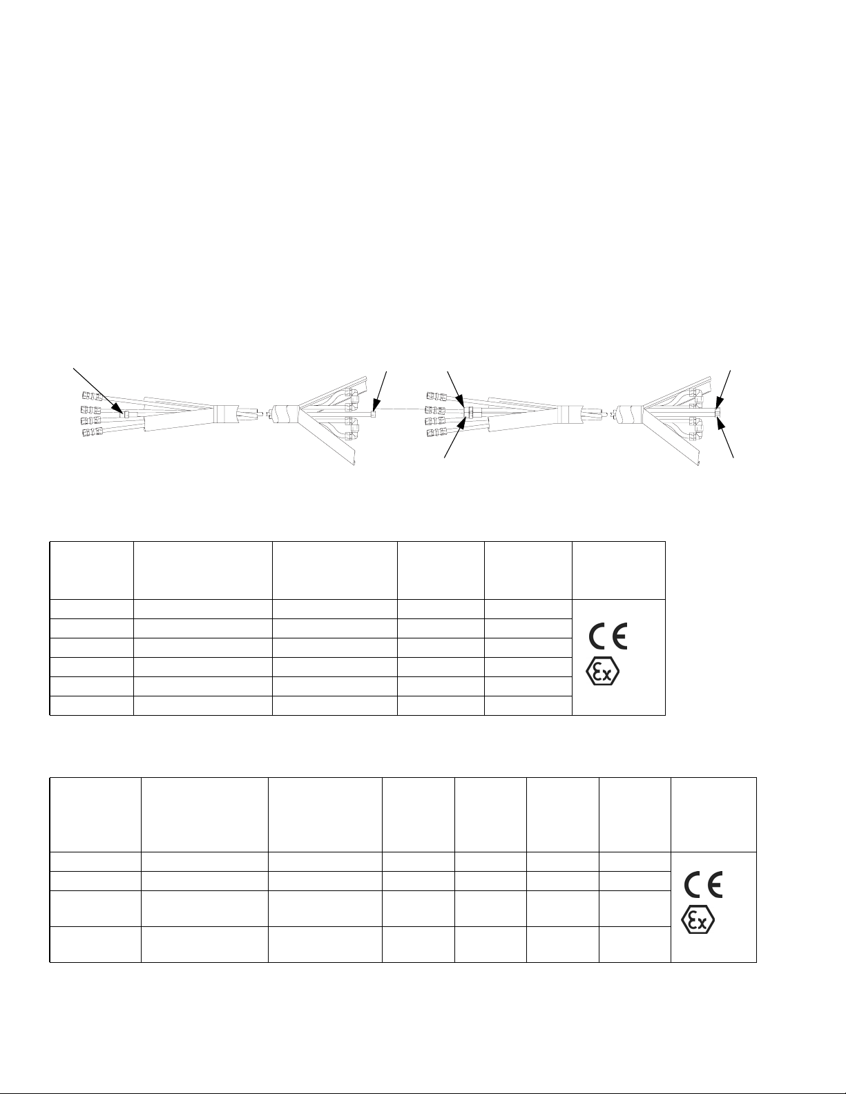
Heated Hose Assembly
Order separately a heated hose assembly that meets maximum pressure and hose diameter requirements. You can
connect up to six 50 ft. (15.2 m) heated hose sections for a maximum total length of 300 ft. (91.4 m).
A
Single Hose Assembly Dual Hose Assembly
B A B
C D
Single Hose Assemblies
Part No.,
Series
245840, C 5000 psi (34, 345) 1/4 (6.35) 1/4 1/4
245841, C 7250 psi (50, 500) 1/4 (6.35) 1/4 1/4
245842, C 5000 psi (34, 345) 3/8 (9.53) 3/8 3/8
245843, C 7250 psi (50, 500) 3/8 (9.53) 3/8 3/8
245844, C 5000 psi (34, 345) 1/2 (12.7) 1/2 1/2
245845, C 7250 psi (50, 500) 1/2 (12.7) 1/2 1/2
Maximum
Pressure Rating
psi (MPa, bar)
Hose Diameter
in. (mm)
Thread A
npt(m)
Thread B
Dual Hose Assemblies
Approvals
npsm(f)
II2G
Part No.,
Series
248118, C 7250 psi (50, 500) 1/2 (12.7) 1/2 1/2 1/2 1/2
248119, C 7250 psi (50, 500) 3/8 (9.53) 3/8 3/8 3/8 3/8
248120, C 7250 psi (50, 500) A = 1/2 (12.7)
248121, C 7250 psi (50, 500) A = 3/8 (9.53)
4 309525G
Maximum
Pressure Rating
psi (MPa, bar)
Hose Diameter
in. (mm)
B = 3/8 (9.53)
B = 1/4 (6.35)
Thread
A
npt(m)
1/2 1/2 3/8 3/8
3/8 3/8 1/4 1/4
Thread
B
npsm(f)
Thread
C
npt(m)
Thread
D
npsm(f)
Approvals
II2G
Page 5
Heated Hose Components
Fluid Heater
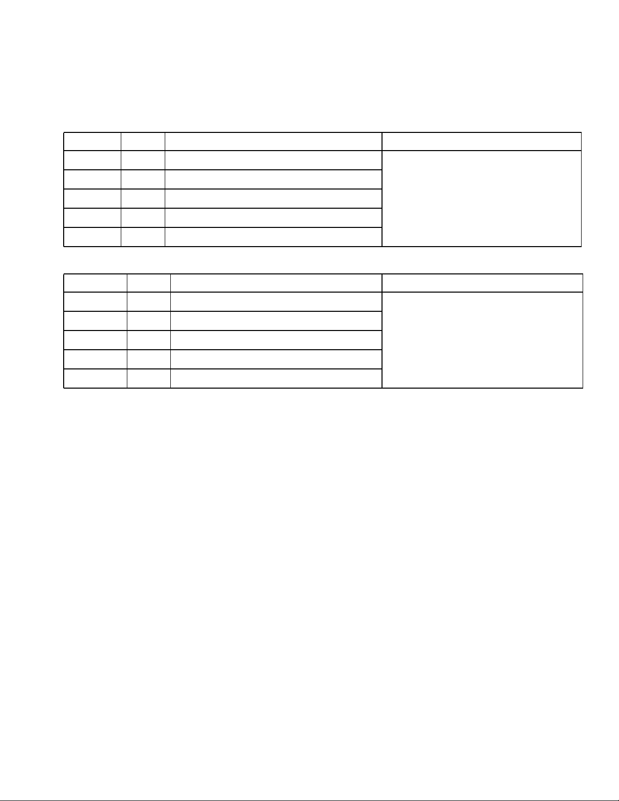
Order separately a VISCON HP heater that meets local electrical and hazardous location requirements.
Hazardous Location Heaters
Part No.
245848 A 120 / 2300 / 19.2
245863 A 240 / 4000 / 16.7
Series
VAC (50/60 Hz single phase) / Watts / Amps
Approvals
245864 A 480 / 4000 / 8.30
245862 A 200 / 4000 / 20.0
246254 A 380 / 4000 / 10.5
Non-hazardous Location Heaters
Model No.
245867 A 120 / 2300 / 19.2
245868 A 200 / 4000 / 20.0
245869 A 240 / 4000 / 16.7
245870 A 480 / 4000 / 8.30
246276 A 380 / 4000 / 10.5
Series
VAC (50/60 Hz single phase) / Watts / Amps
See heater manual 309524 for approvals.
Approvals
See heater manual 309524 for approvals.
309525G 5
Page 6

Heated Hose Components
6 309525G
Page 7

Installation
Installation
5
14, 15
13, 15
1
10, 11, 15
1
B
12, 15
RED
BLUE
3, 7, 22, 25
16
24
6
17
10, 15, 23
1
Resin Hose
14, 15
14, 15
FIG. 1: Fluid and Air Line Connection Schematic
309525G 7
14, 15 C
Catalyst Hose
(optional installation)
C
Page 8

Installation
Installing the Kit
Refer to FIG. 1 and FIG.2
1. Mount pump (16) on the Xtreme Mix cart (D) using
the bracket (21), lockwashers (4), and nuts (2).
2. Mount VISCON HP heater (B-ordered separately)
on the cart using screws and lockwashers (A) supplied with the heater, and the bracket (8), screws
(9), lockwashers (19), and nuts (20) supplied with
the kit.
3. Connect nipple (22) and air regulator (7) to Husky
716 pump. Connect 100 psi (0.7MPa, 7 bar) air supply to the air regulator using air tubing (5), and air fitting (3). Refer to Husky 716 manual if needed.
The air regulator (7) controls pump (16) pressure.
WARNING
7. Interconnect reservoir tank (6), Husky 716 pump
(16), VISCON HP heater (B), and heated hose
(C-F
IG. 1), using tubing (1), tube inserts (15) and fit-
tings (10, 12, 13, 14) as described below.
To ensure a leak-proof seal, use PTFE tape on all
pipe thread connections.
a. Using tubing cutter (19), cut tubing (1) squarely
to desired lengths.
b. Insert tube inserts (15) in tubing (1) ends to
avoid leakage.
c. Insert tubing (1) through the back of the nut in
each of the plastic fittings (10, 12, 13, 14) until
the tube stops. Tighten the nut hand tight, then
tighten it 1-1/2 to 2 turns with a wrench.
Fitting nuts may need retightening as the system
reaches normal operating temperatures.
All wiring must be done by an electrician. See warnings, page 2.
4. Wire VISCON HP heater (B) to your voltage supply.
Follow wiring procedure in the VISCON HP manual.
5. Connect elbow (24), fitting (23), o-ring (17), and reservoir tank (6) to Husky 716 pump (16). On other
side of pump, install bushing (11) and tube fitting
(10).
6. Connect tube fittings (12, 13) to the VISCON HP
heater (B).
Connecting Additional Hose Lengths
Up to six 50 ft. (15.2 m) sections of heated hose can be
attached for a maximum total length of 300 ft. (91.4 m).
1. Remove plastic u-turn fittings at the end of the
heated hose assembly. See FIG.1.
2. Connect the next length of hose, using union fittings
supplied with the hose. Follow fitting assembly procedure in steps 7a-7c, above.
3. Tubes are color coded. Connect like colors.
8 309525G
Page 9

Installation
22
7
3
13
15
15
6
17
1
15
14
1015
11
25
9
A
8
8
10
23
24
B
12
15
1
19
20
15 14
2
4
2
D
FIG. 2: Kit Installation
309525G 9
21
16
4
Page 10

Operation
Operation
Refer to FIG.2
WARNING
Read the warnings, page 2, before operating the
equipment.
1. Select fluid to use for heating circulation.
• If ambient temperatures (storage or operating)
are below 40° F (4.4° C), a 50% water and 50%
antifreeze mixture is recommended.
• If ambient temperatures are above 40° F (4.4°
C), water alone is okay.
Detailed diaphragm pump operating instructions
are in Husky 716 manual.
2. Pour heating circulation fluid into the reservoir tank
(6), increase air regulator (7) pressure, and cycle
the pump (16). Continue to pour fluid into tank until
all air is purged.
Each 50 ft. (15.2 m) heated hose section holds
approximately 1.25 gal. (4.7 liters) of fluid.
3. Fill reservoir tank (6) about half full. Do not overfill;
fluid needs room to expand as the hose heats.
4. Set the flow rate of the circulation fluid to 2 gpm (7.6
lpm) by adjusting the pump’s air regulator (7) until
the pump cycles at 50 cycles/min. Do not use a
higher flow rate as doing so will decrease system
performance and pump life. Never exceed the
hose’s 95 psi (0.6 MPa, 6.6 bar) maximum working
pressure rating.
5. Adjust the heater thermostat to the desired hose
temperature. The setting should be about 10° F
(6° C) higher than the desired paint temperature.
Never exceed the hose’s 180° F (82° C) maximum
temperature rating.
If the hose is not being used for more than one
hour, shut off VISCON HP heater and Husky 716
pump to lengthen heater life.
10 309525G
Page 11

Maintenance
Maintenance
• Check reservoir tank fluid level daily. Add fluid as
needed.
• Follow pump maintenance instructions in Husky 716
manual.
• Follow heater maintenance instructions in VISCON
HP manual.
Troubleshooting
Problem Cause Solution
Fluid leaking out of reservoir tank
when pump is turned off.
Fluid fittings leaking. Loose fittings. Tighten fittings after system reaches
Hose not heating to desired temperature.
Husky 716 pump not operating correctly.
Tank overfilled. Do not fill reservoir tank more than
half full.
desired temperature.
Diaphragm flow rate set too high. Decrease diaphragm pump flow rate.
Problem with VISCON HP heater. See troubleshooting in VISCON HP
heater manual.
See troubleshooting in Husky 716
pump manual.
Related Manuals
Refer to the following manuals for detailed equipment information.
Component Manuals This manual available in following languages:
Manual Description
309524 VISCON HP Heater
308981 Husky 716 Diaphragm Pump
309615 Heater Bracket Kit
Manual Language Manual Language
309525 English 309562 Swedish
309559 French 309588 Chinese
309560 Spanish 309589 Korean
309561 German 309590 Japanese
309525G 11
Page 12

Parts
25
Parts
22
7
3
13
15
15
6
17
1
15
14
1015
11
9
A
8
8
10
23
24
B
12
15
1
19
20
15 14
2
4
2
D
12 309525G
21
16
4
Page 13

Parts
Ref.
No. Part No. Description Qty.
1* --- TUBING; polyurethane; 1/2” (13
mm) OD; 10 ft. (3 m)
2 100015 NUT; 1/4-20 UNC-2B 7
3 C19391 ELBOW; 1/4 nptm x 1/4” (6.35
mm) OD tube
4 100016 LOCKWASHER 7
5* --- TUBING; nylon; 1/4” (6.35 mm)
OD; 6 ft. (1.8 m)
6 188787 RESERVOIR TANK; 1.5 gal. (5.7
liter)
7 110147 AIR REGULATOR; 1/4 npt 1
8 15B336 BRACKET (heater) 1
9 110141 CAP SCREW; 3/8-16 x 1-1/2 in.
(13 mm)
10 116316 FITTING; 1/2-14 npt x 1/2” (13
mm) OD tube
11 117326 BUSHING; 3/4 npt(m) x 1/2 npt(f) 1
12 117423 ELBOW; 1/2 npt(m) x 1/2” (13 mm)
OD tube
13 117424 ELBOW; 1/2 npt(f) x 1/2” (13 mm)
OD tube
Ref.
No. Part No. Description Qty.
14** 117425 TEE; 1/2” (13 mm) OD tube 2
15** 117426 TUBE INSERT; 1/2” (13 mm) OD
tube
16 D53266 716 HUSKY PUMP 1
2
17 104938 O-RING; fluoroelastomer 1
19 106115 LOCKWASHER 2
20 100131 NUT; 3/8-16 2
21 15B337 BRACKET (pump) 1
22 156971 NIPPLE; 1/4 npt 1
1
23 15B338 FITTING 1
24 108307 ELBOW; 3/4 npt(m) 1
25 100139 PLUG, pipe 1
2
* Not available from Graco.
2
** If you are plumbing resin and catalyst hoses in par-
1
allel, purchase 4 additional tees (117425) and 12
additional inserts (117426).
1
6
309525G 13
Page 14

Technical Data
Maximum Working Pressure
High Pressure Fluid Hose ..................... SeeHeated Hose Assembly table, page 4
Heated Fluid Circulation Components ............ 95psi(0.6 MPa, 6.6 bar)
Maximum Temperature Rating ..................... 180° F (82° C)
Wetted Parts
High Pressure Fluid Hose ..................... Nylon, Zinc-Plated Carbon Steel
Heated Fluid Circulation Tubes ................. Nylon
Heated Fluid Circulation Fittings ................ Polypropylene, Aluminum, Brass, Zinc-Plated Carbon
Steel
Reservoir Tank.............................. LowDensity Polyethylene
Heated Hose Dry Weight ......................... 31lb(14.1 kg)
Technical Data
14 309525G
Page 15

Heated Hose Replacement Parts
Order the quantity required for your hose.
101
Heated Hose Replacement Parts
103 105
Ref.
No. Part No. Description
101 117423 ELBOW; 1/2 npt(m) x 1/2” (13 mm) OD
tube
102 117424 ELBOW; 1/2 npt(f) x 1/2” (13 mm) OD
tube
102
Ref.
No. Part No. Description
103 117461 FITTING; 1/2” (13 mm) OD tube
104 117426 TUBE INSERT; 1/2” (13 mm) OD tube
105 246456 HOSE COVER, protective; 50 ft. (15 m)
long
104
Accessory Scuff Jacket
Use to cover and protect heated hose.
85 ft. (25.9 m)
309525G 15
Page 16

Graco Standard Warranty
Graco warrants all equipment referenced in this document which is manufactured by Graco and bearing its name to be free from defects in material
and workmanship on the date of sale to the original purchaser for use. With the exception of any special, extended, or limited warranty published by
Graco, Graco will, for a period of twelve months from the date of sale, repair or replace any part of the equipment determined by Graco to be
defective. This warranty applies only when the equipment is installed, operated and maintained in accordance with Graco’s written
recommendations.
This warranty does not cover, and Graco shall not be liable for general wear and tear, or any malfunction, damage or wear caused by faulty
installation, misapplication, abrasion, corrosion, inadequate or improper maintenance, negligence, accident, tampering, or substitution of
non-Graco component parts. Nor shall Graco be liable for malfunction, damage or wear caused by the incompatibility of Graco equipment with
structures, accessories, equipment or materials not supplied by Graco, or the improper design, manufacture, installation, operation or maintenance
of structures, accessories, equipment or materials not supplied by Graco.
This warranty is conditioned upon the prepaid return of the equipment claimed to be defective to an authorized Graco distributor for verification of
the claimed defect. If the claimed defect is verified, Graco will repair or replace free of charge any defective parts. The equipment will be returned
to the original purchaser transportation prepaid. If inspection of the equipment does not disclose any defect in material or workmanship, repairs will
be made at a reasonable charge, which charges may include the costs of parts, labor, and transportation.
THIS WARRANTY IS EXCLUSIVE, AND IS IN LIEU OF ANY OTHER WARRANTIES, EXPRESS OR IMPLIED, INCLUDING BUT NOT LIMITED
TO WARRANTY OF MERCHANTABILITY OR WARRANTY OF FITNESS FOR A PARTICULAR PURPOSE.
Graco’s sole obligation and buyer’s sole remedy for any breach of warranty shall be as set forth above. The buyer agrees that no other remedy
(including, but not limited to, incidental or consequential damages for lost profits, lost sales, injury to person or property, or any other incidental or
consequential loss) shall be available. Any action for breach of warranty must be brought within two (2) years of the date of sale.
GRACO MAKES NO WARRANTY, AND DISCLAIMS ALL IMPLIED WARRANTIES OF MERCHANTABILITY AND FITNESS FOR A
PARTICULAR PURPOSE, IN CONNECTION WITH ACCESSORIES, EQUIPMENT, MATERIALS OR COMPONENTS SOLD BUT NOT
MANUFACTURED BY GRACO. These items sold, but not manufactured by Graco (such as electric motors, switches, hose, etc.), are subject to
the warranty, if any, of their manufacturer. Graco will provide purchaser with reasonable assistance in making any claim for breach of these
warranties.
In no event will Graco be liable for indirect, incidental, special or consequential damages resulting from Graco supplying equipment hereunder, or
the furnishing, performance, or use of any products or other goods sold hereto, whether due to a breach of contract, breach of warranty, the
negligence of Graco, or otherwise.
FOR GRACO CANADA CUSTOMERS
The Parties acknowledge that they have required that the present document, as well as all documents, notices and legal proceedings entered into,
given or instituted pursuant hereto or relating directly or indirectly hereto, be drawn up in English. Les parties reconnaissent avoir convenu que la
rédaction du présente document sera en Anglais, ainsi que tous documents, avis et procédures judiciaires exécutés, donnés ou intentés, à la suite
de ou en rapport, directement ou indirectement, avec les procédures concernées.
Graco Information
For the latest information about Graco products, visit www.graco.com.
TO PLACE AN ORDER, contact your Graco distributor or call to identify the nearest distributor.
Phone: 612-623-6921 or Toll Free: 1-800-328-0211, Fax: 612-378-3505
All written and visual data contained in this document reflects the latest product information available at the time of publication.
GRACO INC. AND SUBSIDIARIES • P.O. BOX 1441 • MINNEAPOLIS MN 55440-1441 • USA
Copyright 2002, Graco Inc. All Graco manufacturing locations are registered to ISO 9001.
Graco reserves the right to make changes at any time without notice.
Original instructions. This manual contains English. MM 309525
Graco Headquarters: Minneapolis
International Offices: Belgium, China, Japan, Korea
www.graco.com
Revised 10/2011
 Loading...