

Page 1
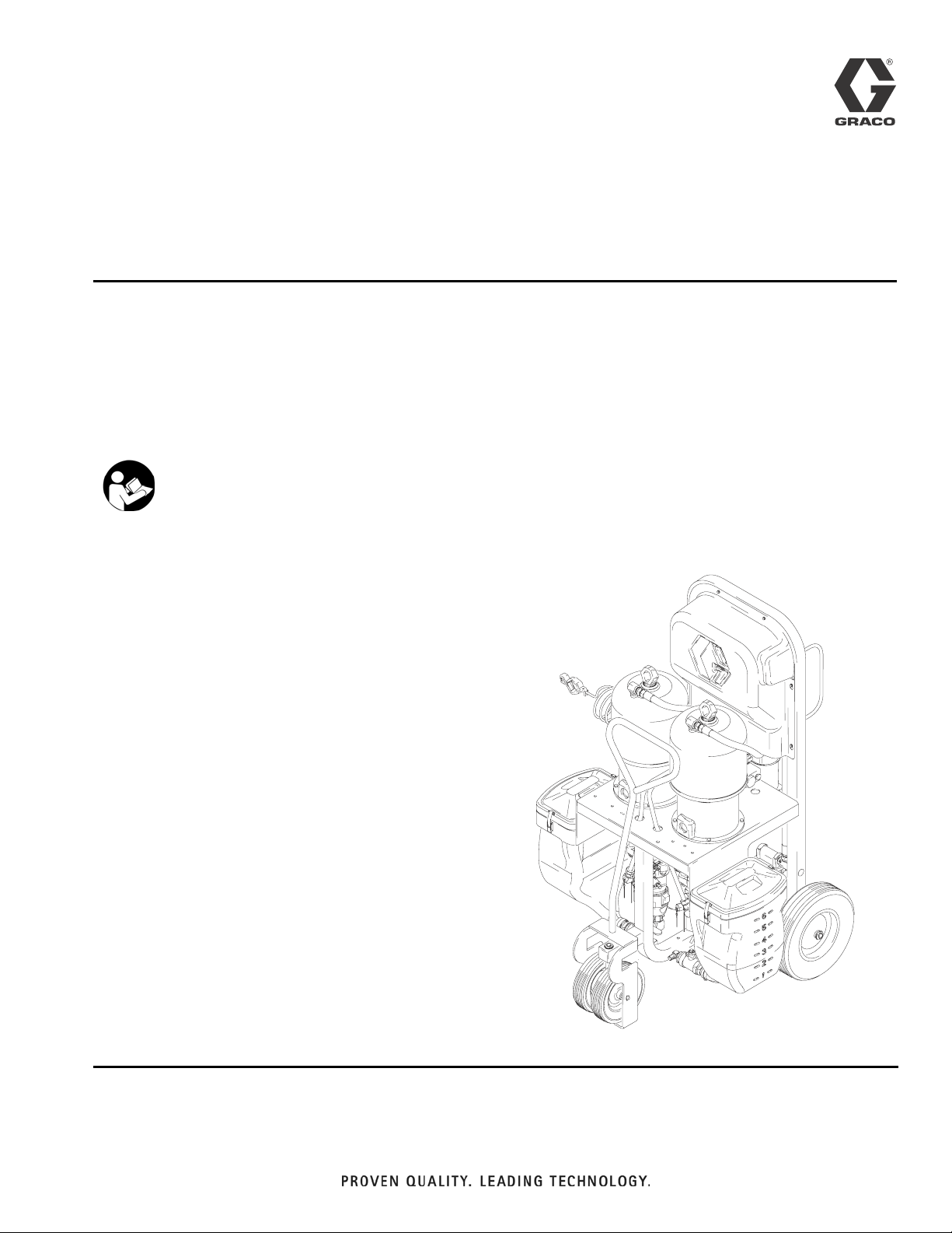
Repair
™
Xtreme Mix
Plural Component Proportioner
For spraying two-component protective coatings.
Not approved for use in explosive atmospheres.
Important Safety Instructions
Read all warnings and instructions in this manual.
Save these instructions
See page 3 for model information, including maximum working pressure and approvals.
309518P
ENG
Page 2

Contents
Xtreme Mix Models . . . . . . . . . . . . . . . . . . . . . . . . . 3
Manual Conventions . . . . . . . . . . . . . . . . . . . . . . . . 4
Related Manuals . . . . . . . . . . . . . . . . . . . . . . . . . . . 4
Warnings . . . . . . . . . . . . . . . . . . . . . . . . . . . . . . . . . 5
Pressure Relief Procedure . . . . . . . . . . . . . . . . . . . 7
Proper Lifting of Unit . . . . . . . . . . . . . . . . . . . . . . . . 8
Grounding . . . . . . . . . . . . . . . . . . . . . . . . . . . . . . . . 8
Shutdown . . . . . . . . . . . . . . . . . . . . . . . . . . . . . . . . . 9
Maintenance . . . . . . . . . . . . . . . . . . . . . . . . . . . . . . . 9
Metering Valve . . . . . . . . . . . . . . . . . . . . . . . . . . 9
Pump . . . . . . . . . . . . . . . . . . . . . . . . . . . . . . . . . . 9
Turbine Alternator . . . . . . . . . . . . . . . . . . . . . . . . 9
Air Filters . . . . . . . . . . . . . . . . . . . . . . . . . . . . . . . 9
Pump Test . . . . . . . . . . . . . . . . . . . . . . . . . . . . . . . 10
Troubleshooting . . . . . . . . . . . . . . . . . . . . . . . . . . . 12
Alarms . . . . . . . . . . . . . . . . . . . . . . . . . . . . . . . . . . 15
Repair . . . . . . . . . . . . . . . . . . . . . . . . . . . . . . . . . . . 16
Replacing Air Filter Element . . . . . . . . . . . . . . . 16
User Interface . . . . . . . . . . . . . . . . . . . . . . . . . . 17
Pneumatic Control . . . . . . . . . . . . . . . . . . . . . . 20
Pump Air Manifold . . . . . . . . . . . . . . . . . . . . . . . 22
Sampling Valve . . . . . . . . . . . . . . . . . . . . . . . . . 23
Metering Valve/Manifold Assembly . . . . . . . . . . 24
Sensor . . . . . . . . . . . . . . . . . . . . . . . . . . . . . . . . 27
Electrical Schematic . . . . . . . . . . . . . . . . . . . . . . . 28
Pneumatic Schematic . . . . . . . . . . . . . . . . . . . . . . 30
Pneumatic/Sensor Connections . . . . . . . . . . . . . 31
Parts . . . . . . . . . . . . . . . . . . . . . . . . . . . . . . . . . . . . 32
Metering Valve Manifold 245824 . . . . . . . . . . . . 41
Metering Valve Manifold 248843 . . . . . . . . . . . . 41
Sampling Valve 245143 . . . . . . . . . . . . . . . . . . 41
Repair Kit 249406 . . . . . . . . . . . . . . . . . . . . . . . 41
Technical Data . . . . . . . . . . . . . . . . . . . . . . . . . . . . 45
Graco Standard Warranty . . . . . . . . . . . . . . . . . . . 48
Graco Information . . . . . . . . . . . . . . . . . . . . . . . . . 48
2 309518P
Page 3
Xtreme Mix Models
WARNING
Do not install equipment approved only for non-hazardous location in a hazardous area. Substitution of
components may impair intrinsic safety. See page 5.
Approved for Non-hazardous Location
Xtreme Mix Models
Xtreme
Mix
Part No. Series
233863 A 249274 45:1 King 4500 (31, 310)
233864 A 249275 56:1 King 5600 (38.6, 386)
233865 A 249276 68:1 King 6800 (46.9, 469)
233866 A 249277 80:1 King 7250 (50, 500)
233867 A 249278 45:1 Quiet King 4500 (31, 310)
233868 A 249279 56:1 Quiet King 5600 (38.6, 386)
233869 A 249280 68:1 Quiet King 6800 (46.9, 469)
233870 A 249281 80:1 Quiet King 7250 (50, 500)
*248842 A 249276 68:1 King
*Model 248842 is designed for remote feed pumps and a remote mix manifold. It does not include hoppers, mix
manifold, hose, or spray gun. Refer to manual 310794 for application layout.
Model 248842 is limited to 5000 psi (34.5 MPa, 345 bar) for use in “quick set” packages where heated hoses,
whip hoses, and spray accessories are limited to 5000 psi (34.5 MPa, 345 bar). If all your downstream components are rated for 7000 psi (48 MPa, 483 bar), you can replace the standard relief valve with relief valve
113498.
Pump
Part No.
Pump
Description
Remote Mix
Maximum Working
Pressure
psi (MPa, bar) Approvals
5000 (34.5, 345)
309518P 3
Page 4

Manual Conventions
Manual Conventions
WARNING
Hazard Symbol
Note
Additional helpful information.
WARNING: a potentially hazardous situation which, if
not avoided, could result in death or serious injury.
Warnings in the instructions usually include a symbol
indicating the hazard. Read the general Warnings
section for additional safety information.
CAUTION
CAUTION: a potentially hazardous situation which, if
not avoided, may result in property damage or
destruction of equipment.
Components A and B
IMPORTANT!
Material suppliers can vary in how they refer to plural
component materials.
Be aware that in this manual:
Component A refers to resin or major volume.
Component B refers to catalyst (curing agent) or minor
volume.
Related Manuals
Component Manuals This manual available in following languages:
Manual Description
309535 Xtreme Mix Operation
311762 Xtreme Displacement Pump
309347 King Air Motor
or 309348 King Quiet Air Motor
312145 XTR Spray Gun
309524 VISCON HP Heater
309525 Heated Hose Kit
308981 Husky 716 Diaphragm Pump
309615 Heater Bracket Kit
309568 Remote Manifold Kit
310797 Remote Mix Manifold
310794 Remote Mix Proportioning Systems
310863 Feed and Flush Kits
309827 Air Supply Kits
Manual Language Manual Language
309518 English 309609 Italian
309564 French 309610 Finnish
309565 Brazilian
Portuguese
309566 Spanish 309612 Chinese
309567 German 309613 Korean
309608 Greek 309614 Japanese
310752 Dutch 310753 Norwegian
310777 Danish
309611 Swedish
4 309518P
Page 5
Warnings
Warnings
The following general warnings are related to the safe setup, use, grounding, maintenance, and repair of this equipment. Additional more specific warnings may be found throughout the text of this manual where applicable.
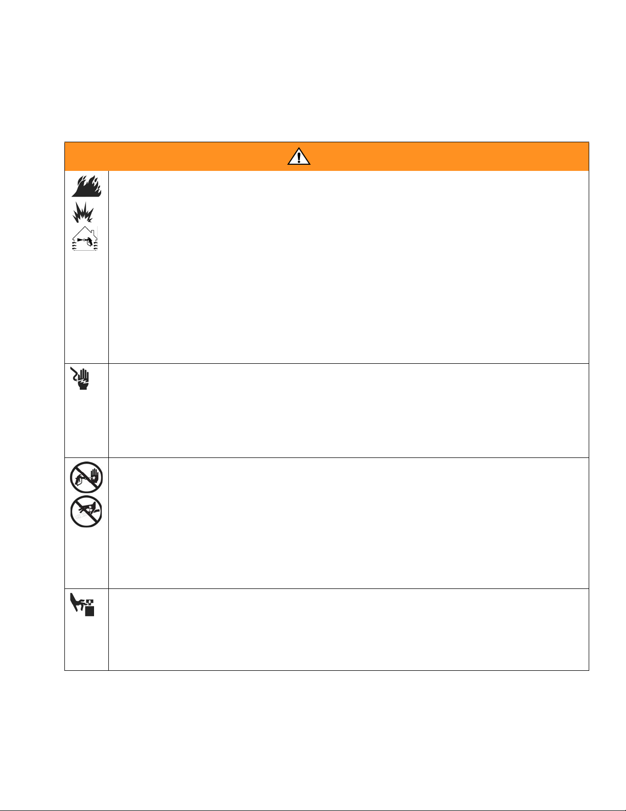
Warning
FIRE AND EXPLOSION HAZARD
Flammable fumes, such as solvent and paint fumes, in work area can ignite or explode. To help prevent
fire and explosion:
• Use equipment only in well ventilated area.
• Eliminate all ignition sources; such as pilot lights, cigarettes, portable electric lamps, and plastic drop
cloths (potential static arc).
• Keep work area free of debris, including solvent, rags and gasoline.
• Do not plug or unplug power cords, or turn power or light switches on or off when flammable fumes
are present.
• Ground equipment and conductive objects in work area. See Grounding instructions.
• Use only grounded hoses.
• Hold gun firmly to side of grounded pail when triggering into pail.
• If there is static sparking or you feel a shock, stop operation immediately. Do not use equipment
until you identify and correct the problem.
• Keep a fire extinguisher in the work area.
ELECTRIC SHOCK HAZARD
Improper grounding, setup, or usage of the system can cause electric shock.
• Turn off and disconnect power at main switch before disconnecting any cables and before servicing
equipment.
• Connect only to grounded power source.
• All electrical wiring must be done by a qualified electrician and comply with all local codes and regulations.
SKIN INJECTION HAZARD
High-pressure fluid from gun, hose leaks, or ruptured components will pierce skin. This may look like just
a cut, but it is a serious injury that can result in amputation. Get immediate surgical treatment.
• Do not point gun at anyone or at any part of the body.
• Do not put your hand over the spray tip.
• Do not stop or deflect leaks with your hand, body, glove, or rag.
• Do not spray without tip guard and trigger guard installed.
• Engage trigger lock when not spraying.
• Follow Pressure Relief Procedure in this manual, when you stop spraying and before cleaning,
checking, or servicing equipment.
MOVING PARTS HAZARD
Moving parts can pinch or amputate fingers and other body parts.
• Keep clear of moving parts.
• Do not operate equipment with protective guards or covers removed.
• Pressurized equipment can start without warning. Before checking, moving, or servicing equipment,
follow the Pressure Relief Procedure in this manual. Disconnect power or air supply.
309518P 5
Page 6
Warning
Warning
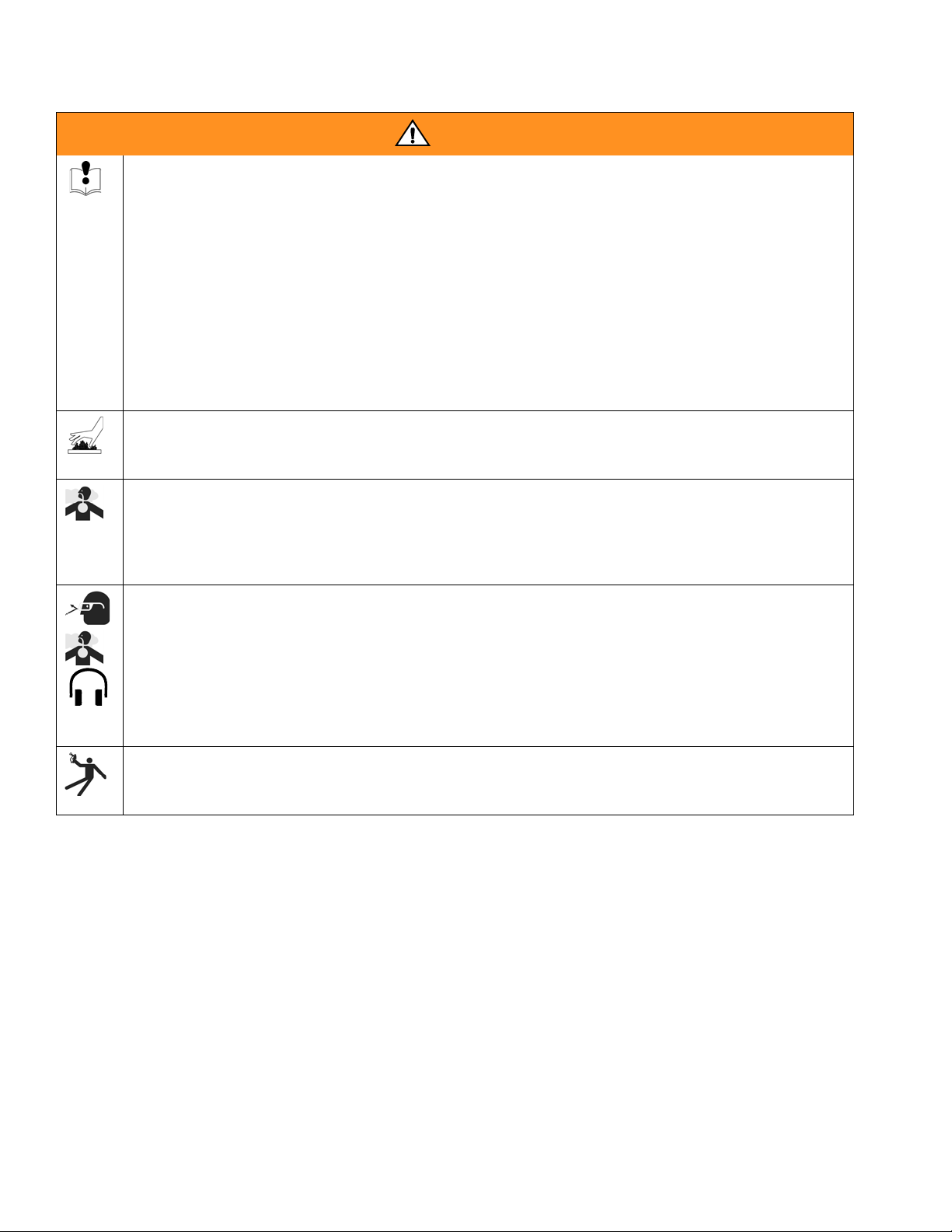
EQUIPMENT MISUSE HAZARD
Misuse can cause death or serious injury.
• Do not exceed the maximum working pressure or temperature rating of the lowest rated system com-
ponent. See Technical Data in all equipment manuals.
• Use fluids and solvents that are compatible with equipment wetted parts. See Technical Data in all
equipment manuals. Read fluid and solvent manufacturer’s warnings.
• Check equipment daily. Repair or replace worn or damaged parts immediately.
• Do not alter or modify equipment.
• For professional use only.
• Use equipment only for its intended purpose. Call your Graco distributor for information.
• Route hoses and cables away from traffic areas, sharp edges, moving parts, and hot surfaces.
• Do not kink or overbend hoses or use hoses to pull equipment.
• Comply with all applicable safety regulations.
BURN HAZARD
Equipment surfaces and fluid that’s heated can become very hot during operation. To avoid severe burns,
do not touch hot fluid or equipment. Wait until equipment/fluid has cooled completely.
TOXIC FLUID OR FUMES HAZARD
Toxic fluids or fumes can cause serious injury or death if splashed in the eyes or on skin, inhaled, or swallowed.
• Read MSDS’s to know the specific hazards of the fluids you are using.
• Store hazardous fluid in approved containers, and dispose of it according to applicable guidelines.
PERSONAL PROTECTIVE EQUIPMENT
You must wear appropriate protective equipment when operating, servicing, or when in the operating
area of the equipment to help protect you from serious injury, including eye injury, inhalation of toxic
fumes, burns, and hearing loss. This equipment includes but is not limited to:
• Protective eyewear
• Clothing and respirator as recommended by the fluid and solvent manufacturer
•Gloves
• Hearing protection
RECOIL HAZARD
Gun may recoil when triggered and cause you to fall and be seriously injured if you are not standing
securely.
6 309518P
Page 7
Pressure Relief Procedure
Pressure Relief Procedure
WARNING
Follow Pressure Relief Procedure when you stop
spraying and before cleaning, checking, servicing, or
transporting equipment. Read warnings, page 5.
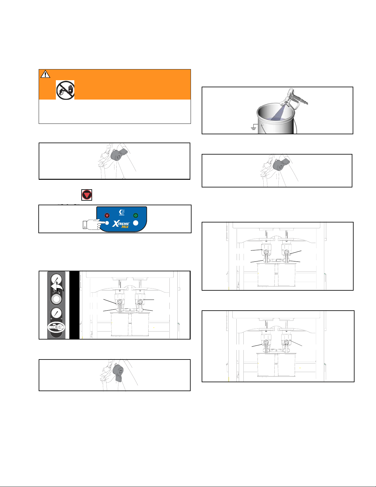
1. Engage trigger lock.
2. Press Stop .
SUPPLY AIR
PRESSURE
I
O
PLURAL COMPONENT PROPORTIONER
3. Close main air shutoff valve on air supply line and on
unit. Turn off air regulator.
4. Close fluid sampling and shutoff valves A and B.
6. Hold a metal part of the gun firmly to a grounded
metal pail. Trigger gun to relieve pressure.
TI5046A
7. Engage trigger lock.
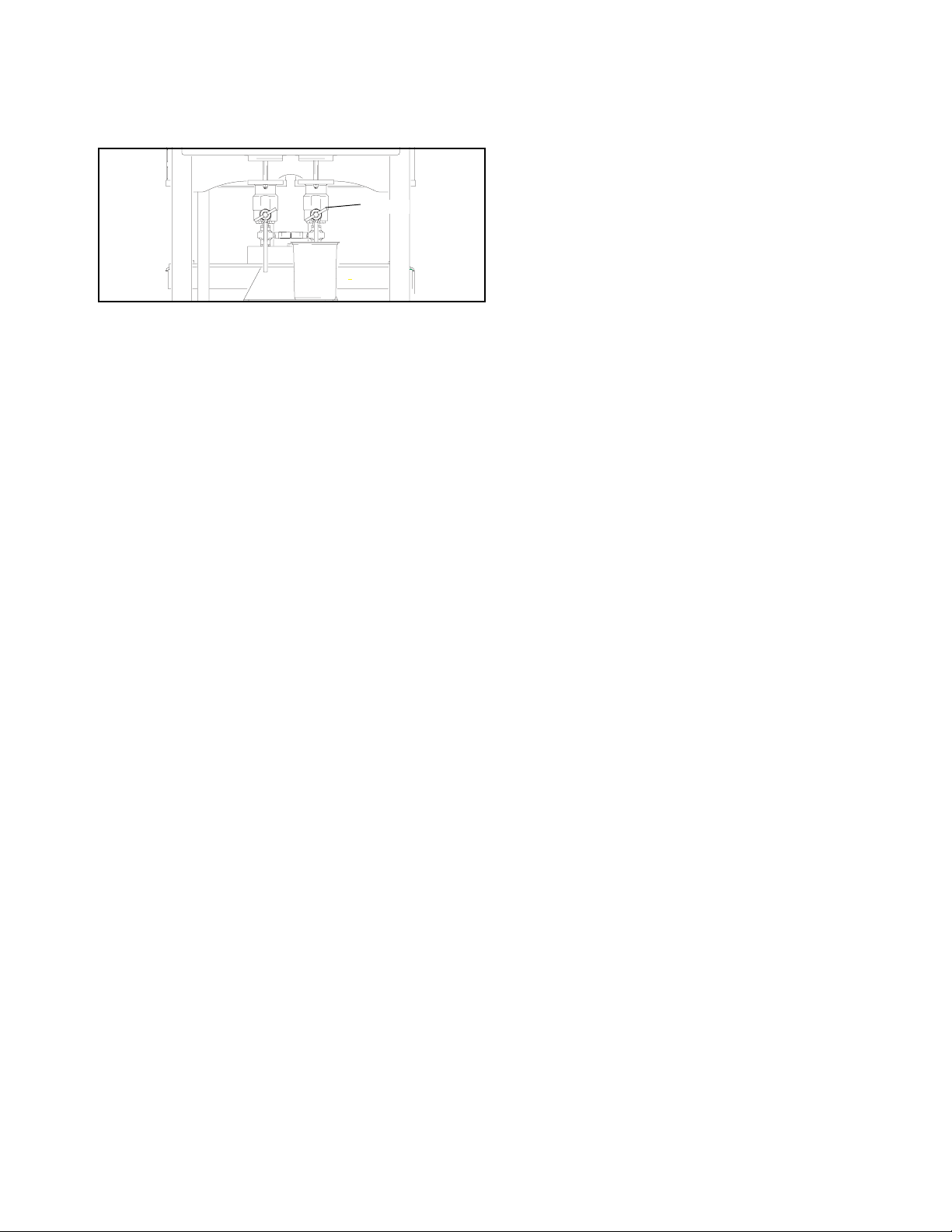
8. Place waste container under sampling valves, then
open valves A and B slowly to relieve pressure
between pump and metering valve.
Open
Close
Open
Close
PSI
Bar
MPa
Close
Close
PSI
Bar
MPa
I
O
5. Disengage trigger lock.
AB
Close
Close
AB
9. Close sampling valves A and B.
Close Close
AB
309518P 7
Page 8
Proper Lifting of Unit
Proper Lifting of Unit
WARNING
Follow instructions below to avoid dropping or swinging unit or being struck by the cart handle, which can
cause serious injury or damage to equipment.
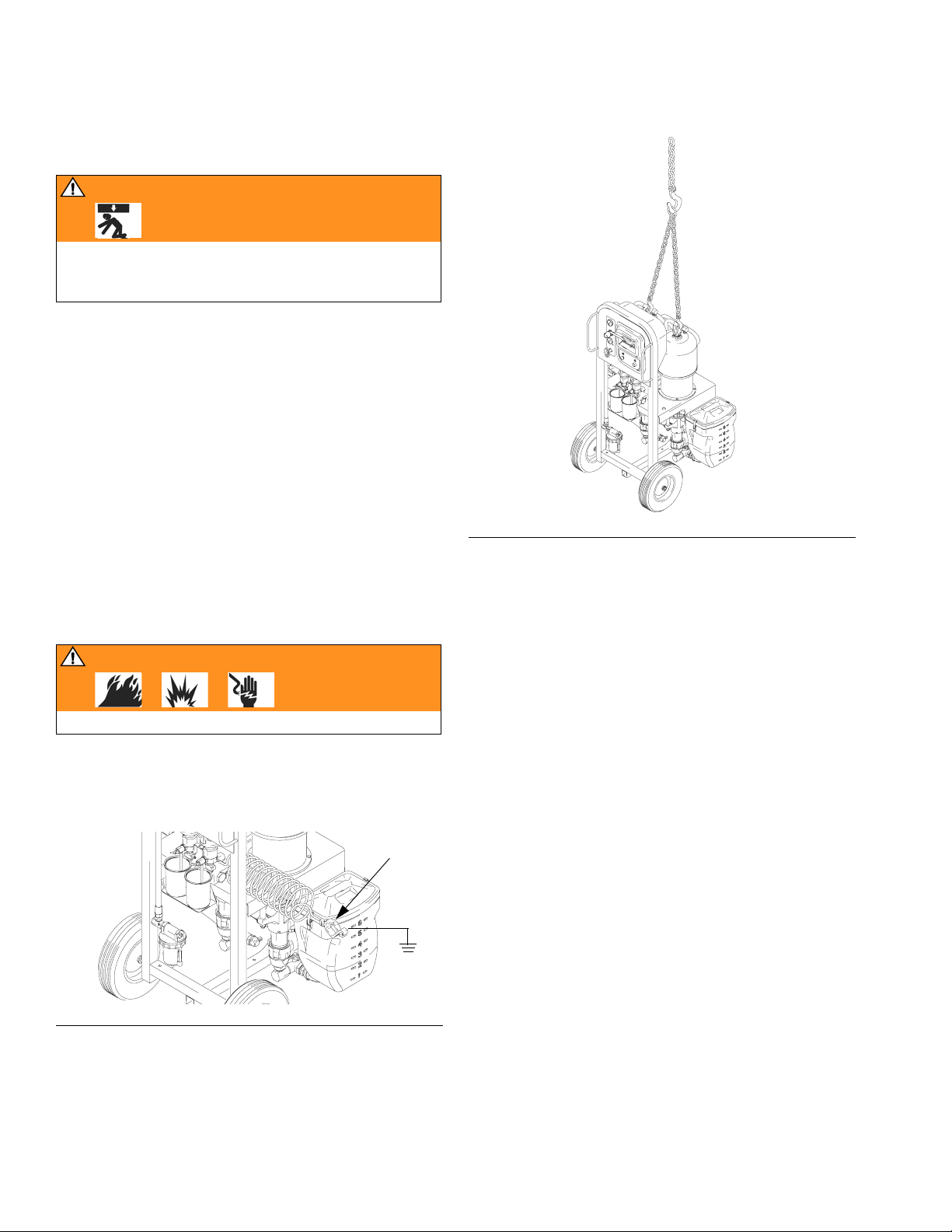
Either remove the cart handle or secure it to the cart
before lifting the unit. Connect a bridle swing, hooking
an end to each of the Xtreme Mix air motor rings. Hook
the center ring on a hoist. See F
Xtreme Mix unit; make sure it balances evenly.
IG. 1. Carefully lift the
Grounding
WARNING
Read warnings, page 5.
If the Xtreme Mix ground wire clamp (G) is disconnected
during repair, be sure to reconnect it to a true earth
ground before starting operation.
G
FIG. 1
IG. 2
F
8 309518P
Page 9
Shutdown
Shutdown
Follow this procedure before prolonged shutdown or
servicing equipment.
If your system includes heaters and heated hose,
make sure they are turned off and cool before
flushing.
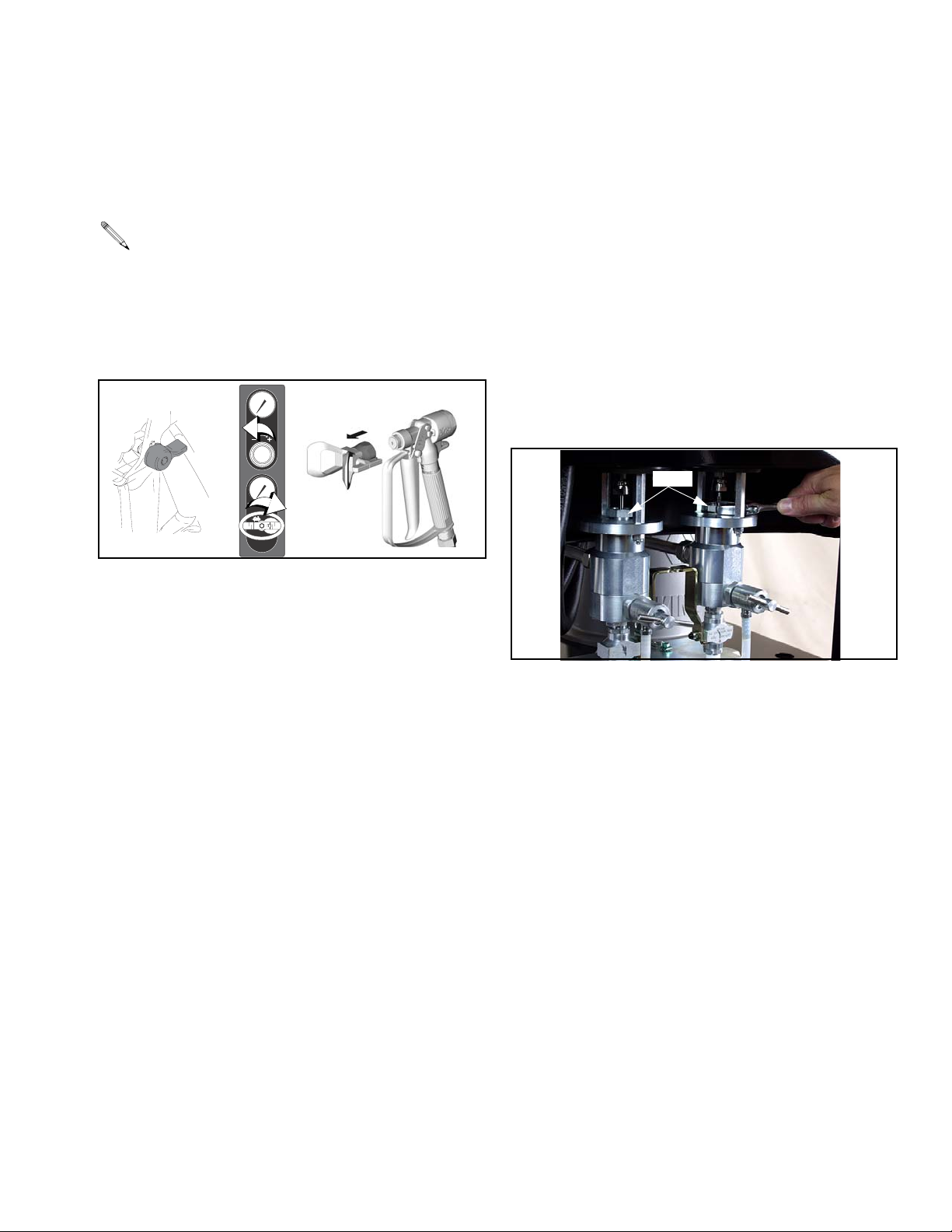
1. Follow Pressure Relief Procedure, page 7. Engage
trigger lock, turn off air regulator, and close main air
shutoff valve. Remove spray tip.
PSI
Bar
MPa
PSI
Bar
MPa
I
O
2. Follow Full System Flushing procedure in the
Xtreme Mix Operation manual.
TI5193
Maintenance
Metering Valve
• Fill metering valves A and B packing nuts (627) with
throat seal liquid (TSL) and tighten 1/4 turn after nut
contacts packings; about 145-155 in/lbs (16-18
N•m). Check packing nut tightness after first hour of
operation, again after 24 hours, then check as
needed (when TSL discolors or seeps over packing
nut). Also check tightness whenever unit is transported.
• Recommend that you replace metering valve packings every other time that pump packings are
replaced.
627
3. Follow Pressure Relief Procedure, page 7.
Engage trigger lock.
4. Before prolonged shutdown: cap fluid outlets to
keep solvent in the lines. Fill pump A and B packing
nuts with throat seal liquid (TSL); follow instructions
in pump manual.
Pump
See pump manual.
Turbine Alternator
Replace bearings every 2000 hours. See page 20.
Air Filters
Check daily. Drain and clean as necessary. See page
16.
309518P 9
Page 10
Pump Test
B
A
B
A
B
A
Pump Test
Follow this procedure the first time system is operated
(after flushing and priming) and whenever you need to
check whether pumps are on ratio.
The following table shows the volume dispensed during
the pump test, based on your pump ratio. Dispense into
a container with adequate graduations.
Pump Volume Dispensed
45:1 750 cc
56:1 660 cc
68:1 540 cc
80:1 435 cc
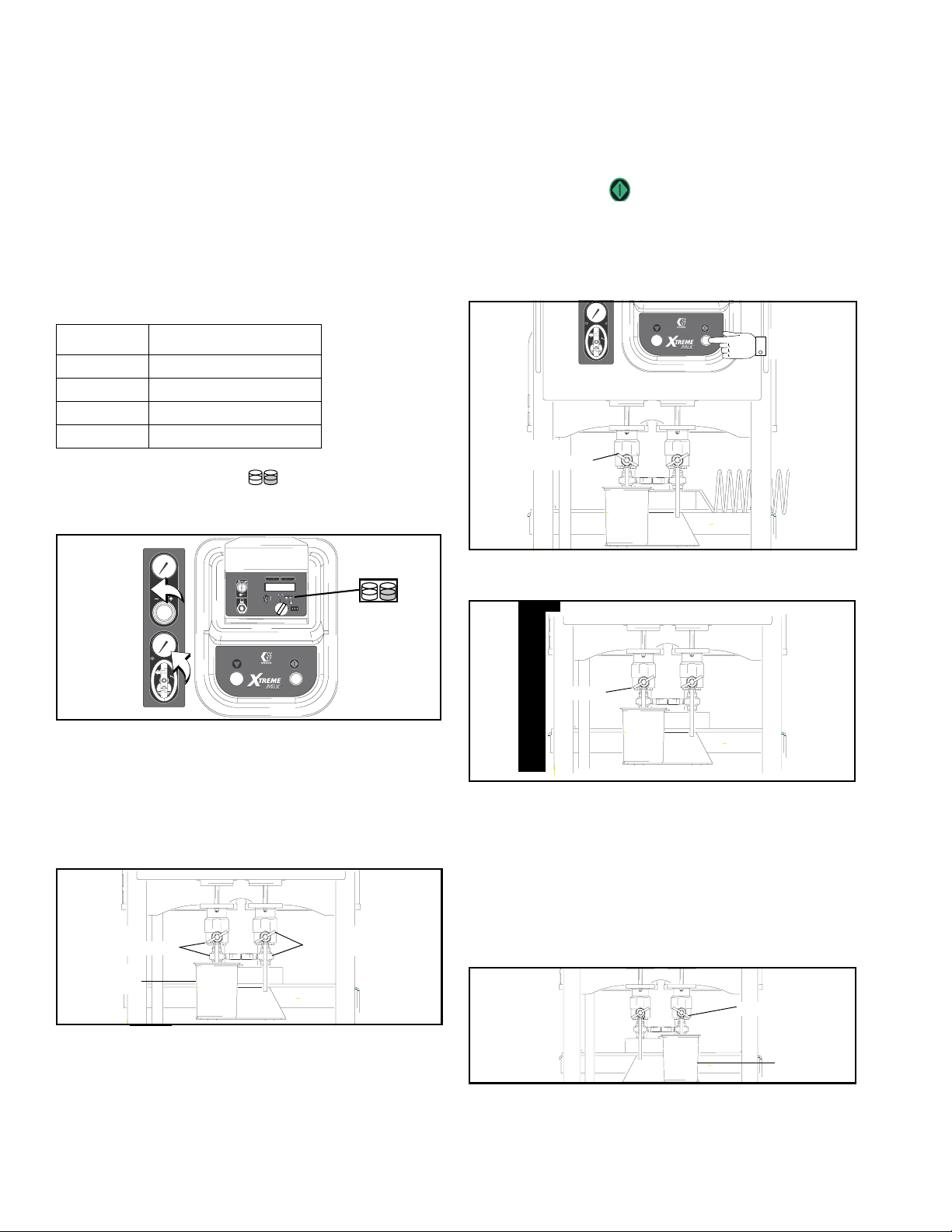
1. Turn knob to pump test . Turn off air regulator.
Open main air shutoff valve. Adjust air pressure to
50 psi (0.35 MPa, 3.5 bar).
c. Press Start . Pump A light comes on.
d. Slowly open and adjust sampling valve A to
achieve desired flow. The pump stops automatically when dispense is complete. Pump A light
turns off, Pump B light comes on.
PSI
Bar
MPa
I
d.
O
Open
c.
A
BA
PSI
Bar
MPa
PSI
Bar
MPa
I
O
0
2. Dispense fluid A:
a. Close fluid shutoff valves and sampling valves A
and B.
b. Place a clean 1 quart (1000 cc) container under
sampling valve A.
Close
a. a.
b.
A
Close
3. Close sampling valve A.
Close
A
4. Dispense fluid B as follows:
a. Place a clean 1 quart (1000 cc) container under
sampling valve B.
b. Slowly open and adjust sampling valve B to
achieve desired flow. The pump stops automatically when dispense is complete. Pump B light
turns off.
Open
b.
B
a.
10 309518P
Page 11
5. Close sampling valve B.
Close
B
6. Compare fluid amounts in the containers; they
should be equal. Repeat test if fluids are not equal.
If problem still persists, see Troubleshooting, page
12.
Pump Test
309518P 11
Page 12
Troubleshooting
Troubleshooting
WARNING
If an error code displays, see page 15.
Read warnings, page 5.
Problem Cause Solution
Display not lit.
No electric power.
Pumps do not run.
Pump test volume is not correct. Air pressure to pumps too low Increase pressure to 50 psi (0.35 MPa,
Air valve not turned on. Turn on main air valve to system.
Air supply pressure too low. Increase pressure to 50 psi (0.35 MPa,
3.5 bar) or greater.
Air supply filters plugged. Clean filter bowls; replace filter elements.
Page 16.
Turbine air regulator set too low. Adjust to proper setting.
Turbine alternator failure. Repair or replace turbine. Page 20.
Power supply not connected to main
board.
Main board not connected to display
board.
Display board failure. Replace display board. Page 18.
Knob set to cycle counter
Air pressure to pumps too low Increase pressure to 50 psi (0.35 MPa,
Air pilot lines are obstructed Check pilot lines for kinks or pinches.
Solenoid valve stuck. Actuate solenoid manually, if it does not
Air pilot valve(s) to motor stuck. Replace valve(s). Page 22.
Metering valve(s) not opening. Service or replace valve(s). Page 24.
Sensors not functioning properly. Check position of sensors. See page 27.
Pump cavitating excessively. Check for air in lines caused by loose fit-
Check power connections to main board.
See Electrical Schematic, page 28.
Check electrical connections between
display and main board. See Electrical
Schematic, page 28.
Set knob to desired setting.
3.5 bar) or greater.
operate, replace solenoid. Page 21.
3.5 bar) or greater.
Check board calibration and recalibrate if
necessary. See page 19.
Replace sensors. Page 27.
ting or use of agitator.
Material too viscous. Use heater.
12 309518P
Page 13

Troubleshooting
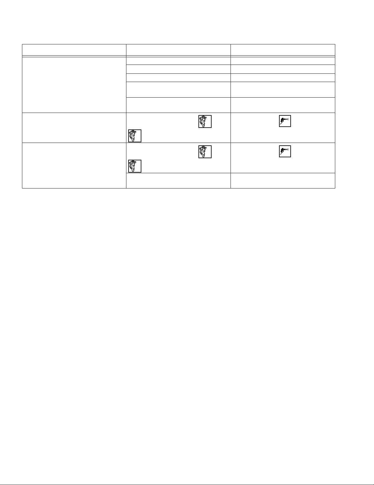
Problem Cause Solution
Paint does not cure consistently. Ratio not set correctly. Check that correct ratio is set and set by
volume. See Xtreme Mix Operation manual.
Material not mixing correctly. Test pump. Page 10.
Make sure mixer is clean; flush as
needed. See Xtreme Mix Operation manual.
Pump not operating correctly. Observe whether pumps are loading and
checking correctly, if not, clean and repair
pump. See pump manual.
Poor spray pattern. Fluid pressure too low. Increase pump pressure.
Spray tip dirty or worn. Relieve pressure. Clean or replace tip.
Follow gun manual instructions.
Fluid A or B filters plugged. Clean filters. See pump manual.
Mixer or hoses partially plugged or too
restrictive.
System runs erratically. Air filter(s) clogged. Replace elements. Clean. Replace element(s). See page 16.
Air supply hoses undersized. Replace hoses with appropriate size.
Air compressor undersized. Use larger air compressor.
Air supply pressure tank undersized. Use larger pressure tank.
Air supply relief valve opens. Turbine air regulator set too high. Lower setting to 23-25 psi (172-241 kPa,
Turbine alternator makes high-pitched
whining noise.
Display shows 88888 or unit reboots
unexpectedly.
Xtreme Mix does not start when start button is pressed.
Fluid valves leaking. Loose or worn packings. Tighten packing nut. If leak continues,
Turbine bearings worn. (Setting turbine
air regulator too high, wears bearings.)
Turbine is not supplying enough power to
board.
Faulty start switch or wire harness. Check start switch and wiring harness
Faulty stop switch or wiring harness. Check stop switch and wiring harness
Bad I/O port on main board. Replace board. Page 17.
Inspect parts for cured material. Clean or
replace, or use larger hoses and mixer.
1.7-2.4 bar).
Replace bearings. Page 20.
Increase turbine regulator setting to
23-25 psi (172-241 kPa, 1.7-2.4 bar).
Check turbine and electrical control
exhaust air for restrictions.
Replace turbine bearings. Page 20.
continuity; switch is normally open circuit.
See Electrical Schematic, page 28.
continuity; stop switch is normally closed
circuit. See Electrical Schematic, page
28.
replace packings. Page 24.
309518P 13
Page 14
Troubleshooting
Problem Cause Solution
Flow rate too low. Inadequate air supply. Use larger CFM compressor.
Air pressure to pumps too low. Increase pressure.
Fluid A or B filters plugged. Clean filters. See pump manual.
Spray tip too small. Relieve pressure. Install larger tip. Follow
gun manual instructions.
Mixer or hoses partially plugged or too
restrictive.
Inspect parts for cured material. Clean or
replace, or use larger hoses and mixer.
Pump stops after 12 cycles.
Xtreme Mix makes chirping noise every
60 seconds.
Knob is set to
independently.
B
Knob is set to
independently.
B
Run pump A or B
Run pump A or B
A
A
Material too heavy to siphon or gravity
feed.
Turn knob to spray
if spraying mate-
rial.
Turn knob to spray
if spraying mate-
rial.
Change material feed/supply method.
14 309518P
Page 15

Alarms
Alarms
• An alarm condition will shutdown the equipment.
• A chirping sound every 60 seconds indicates
* Indicates error where audible alarm sounds once briefly.
** Indicates error where audible alarm sound pulses.
the unit is set for recirculation mode.
Code Alarm Active Problem Cause
Startup Errors
01 Sensor Error A* Always No signal from pump A sensor. Loose cable, failed sensor or cable.
Page 27.
02 Sensor Error B* Always No signal from pump B sensor. Loose cable, failed sensor or cable.
Page 27.
03 Controller Error* Always Loss of communication between main
and display boards.
Operating Errors
04 Pump Runaway A** Spray
05 Pump Runaway B**
06 Pump Error A** Spray
07 Pump Error B**
08 Sensor Code Error Always Software boot, sensor values reverted to
09 Metering Error A** Spray A dose too great. Metering valve A leak. Page 24.
Te st
Batch
Te st
Batch
Pump running too fast.
This alarm is not active when
pumps are run independently.
Pump does not stall after top change
over.
Pump cavitating excessively.
default.
Loose cable, failed board. Page 17.
Empty fluid reservoir(s).
Clogged fluid filter.
Hose rupture after mix manifold.
Sampling valve open too far.
Excessive cavitation.
Foot valve leak.
Air in lines caused by loose fitting or
use of agitator.
Empty fluid reservoir(s).
Sensor value data corrupt; board
needs replacement and /or recalibration. Page 17-19.
Empty B fluid reservoir.
10 Metering Error B** Spray B dose too great. Metering valve B leak. Page 24.
Empty A fluid reservoir.
11 Sensor Reading Low A* Always Pump stroke travels beyond sensor
12 Sensor Reading Low B*
13 Sensor Reading High A* Always Pump stroke travels beyond sensor
14 Sensor Reading High B*
range at bottom change over.
range at top change over.
Sensor or bracket loose. Page 27.
Sensor magnet dirty.
Sensor or bracket loose. Page 27.
Sensor magnet dirty.
Testing Error
15 Piston packing/ball A* Test Pump does not completely stall in up
16 Piston packing/ball B*
17 Inlet Ball A* Test Pump does not completely stall in down18 Inlet Ball B*
19 Metering Valve A* Test Pump does not completely stall in both
20 Metering Valve B*
309518P 15
stroke.
stroke.
up and down strokes.
Piston packing or ball check failure.
Foot valve ball check failure.
Throat packing or metering valve fail-
ure. Page 24.
Page 16

Repair
Repair
Follow Shutdown procedure, page 9, if service time
may exceed pot life time, before servicing fluid components, and before transporting equipment to a service
area.
WARNING
Read warnings, page 5.
Replacing Air Filter Element
There are 2 air filters on the unit: the 5 micron air manifold filter (518) and 40 micron pump air filter (8). Check
filters daily and replace element as needed.
WARNING
Removing the bowl of a pressurized air filter could
cause serious injury. Do not service air filter until air
line is depressurized.
3. Unscrew filter bowl. F
F
IG. 4
4. Remove and replace element.
5. Screw filter bowl on securely.
IG. 4.
Pump Air Filter
2. Unscrew filter bowl. FIG. 5.
Both Filters
1. Close main air shutoff valve on air supply line and
on unit. Depressurize air line.
Air Manifold Filter
2. Remove air manifold cover (42). FIG. 3.
43
42
F
IG. 3
IG. 5
F
3. Unscrew plate.
4. Remove and replace element. F
IG. 6
F
5. Reassemble.
IG. 6.
16 309518P
Page 17

User Interface
Repair
Removing Cover
1. Close main air shutoff valve on air supply line and
on unit.
2. Remove air manifold cover (42). F
3. Remove four nuts (32) and open user interface
cover (4). F
F
IG. 7
IG. 7–FIG. 8.
315
IG. 3, page 16.
32
301
406
416
C
D
F
IG. 9
3. Install new chip (beveled corner down).
4. Reassemble.
5. Recalibrate main circuit board. See page 19.
Replacing Main Circuit Board
CAUTION
To avoid damaging circuit board, wear a grounding
strap.
1. Remove User Interface cover. See above.
2. Disconnect all wire connectors from board (301).
F
IG. 10.
4
F
IG. 8
4. To completely remove cover (4), disconnect ground
wire (315), wires (416 and 406) from main board
(301). See F
IG. 8 and Electrical Schematic, page
28.
Software Upgrades
CAUTION
To avoid damaging circuit board, wear a grounding
strap.
1. Remove User Interface cover. See above.
2. Use a chip remover (D) to remove software chip (C).
F
IG. 9.
3. Remove four screws (302) and replace board (301).
4. Reassemble. Refer to Electrical Schematic, page
28.
5. Recalibrate main circuit board. See page 19.
10 9 8 7 6 5 4 3
301
302
6
5
10
9
7
8
3
4
-
+
F
IG. 10
309518P 17
Page 18

Repair
Replacing Display Circuit Board
CAUTION
To avoid damaging circuit board, wear a grounding
strap.
411
410
1. Remove User Interface cover. See page 17.
2. Disconnect wires from display board (410). F
IG. 11.
3. Remove two screws (411).
4. Remove setscrew (B) from knob (405) and remove
knob assembly.
5. Remove and replace display board (410).
6. Reassemble. Refer to Electrical Schematic, page
28.
Ref.
416
416
406
Back View
B
1
405
1
Align knob to allow for turning to all 6 settings.
FIG. 11
18 309518P
Page 19

Recalibrate Circuit Board
B
A
Follow this procedure whenever the main circuit board,
software, or sensor is replaced, or when Alarm 8 occurs
(refer to page 15).
1. Note calibration value on pump A sensor. Refer to
F
IG. 23, page 27.
2. Open main air valve to start unit.
Repair
3. Turn knob to pump A . F
IG. 12. Hold down
A
Stop button about 5 seconds. The default calibration (number between 85000 - 95000) displays.
4. Use key (X) to change default to calibration value
noted previously.
5. Note calibration value on pump B sensor.
6. Turn knob to pump B . Hold down Stop
B
button about 5 seconds. The default calibration displays.
7. Use key (X) to change default to calibration value
noted previously.
X
BA
PSI
Bar
MPa
PSI
Bar
MPa
I
O
0
A or B
F
IG. 12
If data download is used, set date and time after
calibrating, using Xtreme Mix software.
309518P 19
Page 20

Repair
Pneumatic Control
Alternator Repair
Turbine Alternator Repair Kit 223688 is available to
replace turbine bearings.
1. Remove User Interface cover. See page 17.
306r
10 9 8 7 6 5 4 3
P
301
304
6
5
10
9
7
8
3
4
-
+
F
IG. 13
2. Disconnect power supply wires (P). F
IG. 13.
310
3. Disconnect two air lines (310) from alternator (304).
F
IG. 14.
4. Remove top nut (305) and loosen bottom nut. Slide
alternator up and off bottom nut.
IG. 14
F
305
1
304
304d
310
A
304a
304d
304e
5. Remove four screws (304d) to separate alternator
housings. F
IG. 15.
6. Disconnect turbine (304e) from board (A). Follow
1
Torque to 20 in-lbs (2 N•m)
IG. 15
F
instructions in turbine kit manual 308034 to remove
and repair turbine.
7. Replace gasket (304a) if damaged. Place between
housings before securing with screws (304d).
8. Reassemble. Refer to Electrical Schematic, page
28.
• Lightly lubricate turbine o-ring before installing turbine in housing.
• Connect alternator red wire to + side and
black wire to – side of main circuit board.
• Connect turbine to 3-pin connector on main
circuit board.
20 309518P
Page 21

Repair
Replacing Solenoids
Follow this procedure to replace a single solenoid.
1. Remove User Interface cover. See page 17.
2. Disconnect two solenoid wires (V) from main board.
F
IG. 16.
3. Remove two screws (S).
4. Remove and replace solenoid (306b).
From left to right, solenoid functions are as follows:
• Metering valve A
• Metering valve B
• Pump A
• Pump B
5. Reassemble. Solenoid wires are polarized (red +,
black –). Refer to Electrical Schematic, page 28.
Replacing Alternator Regulator
1. Remove User Interface cover. See page 17.
3. Disconnect supply and exhaust air lines (310).
4. Disconnect solenoid wires 12 position Phoenix connector (306r) from main board. F
IG. 13, page 20.
5. Remove solenoid module (306) with regulator
(306e). F
IG. 16.
6. Unscrew and replace regulator (306e).
7. Reassemble. Refer to Electrical Schematic, page
28.
Make sure gaskets (306j, 306k) are in place when
reinstalling solenoid module.
8. Set regulator to 24 psi (160 kPa, 1.6 bar).
Replacing Alarm
1. Remove User Interface cover. See page 17.
2. Disconnect alarm wires from main board.
3. Unscrew alarm (313) and replace. F
IG. 16.
2. Remove two screws (309). F
306k
S
306b
1
306e
306j
IG. 16.
V
306
4. Reassemble. Refer to Electrical Schematic, page
28.
309
310
313
1
Set regulator pressure to 24 psi (160 kPa, 16 bar)
F
IG. 16
309518P 21
Page 22

Repair
Pump Air Manifold
1. Close main air shutoff valve on air supply line and
on unit.
2. Pull off regulator knob (R). F
3. Remove two screws (44).
4. Disconnect two hoses (515) from pump motors.
5. Replace parts as needed. See page 40.
6. Reassemble.
IG. 17.
F
IG. 17
5
R
515
44
22 309518P
Page 23

Sampling Valve
WARNING
Read warnings, page 5.
1. Follow Pressure Relief Procedure, page 7.
2. Unscrew sampling valve assembly (83) from metering valve (601).
3. Unscrew seat (83c).
4. Remove o-rings (83f), ball (83d), seat (83g), and
gasket (83h).
5. Replace parts as needed and reassemble.
Repair
83c
83h
83g
83d
1
83f
83b
1
83e
606 (side A)
611 (side B)
83a
2
84
85
1
Lubricate.
2
Apply anaerobic sealant. Torque to 130-140 in-lbs (15-16 N•m)
F
IG. 18
601
607
309518P 23
Page 24

Repair
Metering Valve/Manifold Assembly
WARNING
Read warnings, page 5.
Removing Assembly
1. Follow Pressure Relief Procedure, page 7.
2. Disconnect top and bottom black air tubes.
3. Unscrew fluid tube.
4. Remove nuts (26), screws (27, 48) and lockwashers
(25). F
IG. 19.
5. Remove metering valve manifold (6).
Removing Metering Valve
1. Remove Metering Valve/Manifold Assembly.
Servicing Metering Valve
Follow this procedure to replace packings. Reference
numbers with * are included in repair kit 234098. Reference numbers with † are included in repair kit 234131.
1. Remove metering valve.
2. Remove two locknuts (636). F
3. Remove packing nut (627).
4. Remove inlet housing (628).
5. Unscrew needle (630*) from piston rod (625).
6. Remove packings (637*, 638, 639*). Inspect needle
(630*) and replace if worn.
If piston valve packings need replacement:
7. Unscrew cap (622).
8. Unscrew locknut (631).
9. Remove piston (623) and replace o-rings (632*†,
633*†, 634*†).
IG. 20.
2. Unscrew metering valve (601) from shutoff valve
(606 or 611).
3. If necessary, remove and repair or replace shutoff
valve (606 or 611). See manual 306861.
48*
27
25
6
Manifold
245833
26
FIG. 19
25
601
606 (side A)
611 (side B)
607a
10. Replace piston rod o-ring (643*†) if damaged.
11. Reassemble.
48
25
48
25
6
Manifold
248843
26
26
24 309518P
Page 25

Repair
621
5
622
*† 634
*
† 632
4
631
7
623
*† 633
† 635
624
*† 643
8
*† 638
8
629
*† 637
6
627
626
8
4
639*†
628
4
636
3
630†
8
645*†
644†
645*†
646
9
10
9
9
625
1. Apply pipe sealant to non-swiveling pipe threads.
2. Apply lubricant to threads, o-rings, and seals.
3
Apply medium anaerobic adhesive. Thread to bottom.
4
Torque to 5-7 ft/lbs (7-9 N•m).
5
Torque to 30-40 ft/lbs (41-54 N•m).
6
Tighten packing nut 1/4 turn after nut bottoms out; 145-155 in/lbs
(16-18 N•m). Check packing nut tightness about once a month.
Keep packing nut filled with TSL.
7
Lubricate and press piston evenly into cylinder.
FIG. 20
621
647
5
8
Clean needle (630) and packing cavity before reinstalling
packings (637*, 638, 639*). Lubricate packings and install with
lips facing up toward packing nut (627) in order shown.
9
Whenever the seat housing (646) is removed, replace the o-rings
(645).
10
Inspect reversible seat for damage. If one side is worn, reverse
seat.
309518P 25
Page 26

Repair
Servicing Fluid Manifold 245833
Follow this procedure to replace packings. Reference
numbers with * are included in repair kit 234100.
1. Remove metering valve. See page 24.
2. Unscrew plug (661).
3. Remove and replace o-rings (662*, 663*, 665*),
seat (664*), ball (666*), and spring (667*).
CAUTION
Do not assemble static mixer directly to fluid manifold.
Install static mixer after first 50 ft. (15 m) of hose to
ensure material is completely mixed. Spraying
unmixed material could necessitate rework of part
sprayed. See Setup in Xtreme Mix Operation manual.
Servicing Fluid Manifold 248843
4. Reassemble.
661
*662
*663
*665
*664
*665
*666
*667
Manifold 245833
1. Apply pipe sealant to non-swiveling pipe threads.
2. Apply lubricant to threads, o-rings, and seals.
674
675
There are no serviceable parts on manifold 248843.
676
669
665
670
668
FIG. 21
26 309518P
Page 27

Repair
Sensor
CAUTION
To avoid damaging board, wear a grounding strap.
Reference numbers with * are included in repair kit
246345. Reference numbers with † are included in
repair kit 246344.
1. Close main air shutoff valve on air supply line and
unit. F
IG. 22.
B
A
PLURAL COMPONENT PROPORTIONER
VALVEBAVALVE
IG.
0
SETUP KEY
DATA PORT
IG. 22
F
PUMP AIR
PRESSURE
PSI
Bar
MPa
SUPPLY AIR
PRESSURE
PSI
Bar
MPa
I
I
O
O
2. Unscrew sensor cap (701†) from nut (712†). F
23.
3. Disconnect cable (705*).
†712
†714
†707
†706
1
†708
704†
703†
701†
720†
710*
709*
702*
3
4
705*
719*
Y
2
713*
721*
711*
4. Unscrew fitting (713*), locknut (719*), and cover
(702*).
5. Disconnect sensor cable (Y) from board (703†).
6. Remove and replace parts as needed.
7. Reassemble and mount sensor. Refer to Electrical
Schematic, page 28.
Mount sensor as close to magnet as possible
without touching it.
8. Recalibrate main circuit board. See page 19.
Displacement Pump
WARNING
Read warnings, page 5.
1
Torque to 60 in-lbs (7 N•m).
2
Plug connector into connector on board (703).
3
Calibration value location.
4
Before assembling cover (702*) to cap (701
†), assemble cable
(705*) through fitting (713*) and cover (702*), and plug cable into
connector on board (703
†) and to ground lug.
FIG. 23
2. Disconnect 90° swivel (30) from pump lower. Refer
to page 32.
3. Remove pump lower and service as instructed in
pump manual 311762.
1. Follow Pressure Relief Procedure, page 7.
309518P 27
Page 28

Electrical Schematic
Electrical Schematic
*
Jumper (15V)
*
*
*
*
Main Circuit
Board
245705
6$#
#/-
2
",
Solenoids
",7
",2
",'
2
3
7
2
'
7
",7
",2
'
",'
3
Metering Valve A
Metering Valve B
Pump A
Pump B
Metering
Valves
Air Motors
Sensor
243678
B
Sensor
243678
A
2
",
2
",
2
",
2
",
2
",
Case Gnd Clip
2
7
",
*
Key:
BL Black
BR Brown
BL-GBlack with green
BL-RBlack with red
28 309518P
BL-WBlack with white
G Green
GNDGround
R Red
S Shield
W White
Page 29

Electrical Schematic
301
Power
Supply
Barrier
Board
Alarm 15A849
Alarm +
Alarm COM
2
7
",
304
Power
Supply
Air Input
Front Panel
COM Port
RS232
Connector
Start
Comport Pin
Front View
48
28
'.$
"
!
'.$
Start/Stop
Switch
15A851
Light
Stop
'.$
Key
Switch
15A852
Display Board
245706
*
*
2
7
"2
'
",
",
2
'
Key Switch
momentary
309518P 29
Page 30

Pneumatic Schematic
Pneumatic Schematic
Manifold
1/2 in. x 24 in. long
Air
Exhaust
Air Supply
e
s
o
12 VDC
Solenoid
A Metering
.
n
i
2
3
/
Cl
A
Position 1
Val ve
n
e
p
O
5
A
Val ve
B Metering
.
n
i
n
e
2
p
3
e
/
s
O
5
o
l
B
C
B
A Pilot
To P u mp
3-way valve
B Pilot
To P u mp
3-way valve
304
Turbine / Power Supply
306t
12 VDC
Solenoid
Position 2
12 VDC
Solenoid
Position 3
12 VDC
Solenoid
Position 4
26 psi (79 kPa, 1.8 bar)
Relief Valve
To Manifold
3/8 in. tube
524
B Pilot
Pump A Pilot
Pump
306e
Alternator Air
Regulator
501
90/110 psi 0.6/0.8
MPa, 6.2/8 bar)
Relief Valve
110 psi
(0.8 MPa,
8 bar) Relief
79
King Motor B
King Motor A
Gauge
Val ve
518
3/4 in. Ball Valve
3/8 in. Air Reg.
Auto Drain
5 micron
Gauge
100 psi (0.7
MPa, 7 bar)
bleed type
503
8
Air Regulator
3/4 in. Air Filter
Auto Drain
20 micron
FIG. 24
30 309518P
Page 31

Pneumatic/Sensor Connections
Pneumatic/Sensor Connections
A
B
C
F
G
H
J
D
E
K
L
Key:
A Pump A Air
B Pump B Air
C Pump A Pilot Air
D Pump B Pilot Air
E Air Supply
F Metering Valve A - CLOSE
G Metering Valve A - OPEN
H Metering Valve B- CLOSE
J Metering Valve B- OPEN
K Sensor A Cable
L Sensor B Cable
FIG. 25
309518P 31
Page 32

Parts
Parts
Xtreme Mix Proportioner
Parts shown here and page 34 and 36.
DETAIL D
Ref. 6
47
(side B) 45
(side A) 46
86
Ref. 3, 4, 5
47
49
Parts for
Model 248842
Ref. 6
47
49
47
(side B) 45
(side A) 46
TI2321A
43
42
Ref. 62
1
See
DETAIL C
*26
*25
*87
See
DETAIL B
See DETAIL
A & D
*87
*8
17,29,37,
38,40
Ref. 6
24
25
63
2
11,12,13
7
26
Ref. 71
66
97**
97b
97c
90**
97d
97a
97e
32 309518P
TI2321B
*59
*60
*33
*30
81
80
86
6864
(blue) *16
(green) *78
65
TI2317A
Page 33

Xtreme Mix Proportioner
Part Number Table
Parts
Refer to page 3 for additional model information.
Approved for Non-hazardous Location
Xtreme
Mix Pump (2)
233863 249274 (45:1) 245824 XTR704 H53850 15B729 113498 15A914 15A915
233864 249275 (56:1) 245824 XTR704 H53850 15B729 113498 15A914 15A915
233865 249276 (68:1) 245824 XTR704 H73850 15B729 113498 15A914 15A915
233866 249277 (80:1) 245824 XTR704 H73850 15B729 116643 15A914 15A915
233867 249278 (45:1) 245824 XTR704 H53850 15B729 113498 15A914 15A915
233868 249279 (56:1) 245824 XTR704 H53850 15B729 113498 15A914 15A915
233869 249280 (68:1) 245824 XTR704 H73850 15B729 113498 15A914 15A915
233870 249281 (80:1) 245824 XTR704 H73850 15B729 116643 15A914 15A915
248842 249276 (68:1) 248843 none none none 108124 15A914 15A915
Metering
Valve (6)
Gun
(15)
Hose
(20)
Coupling
(56)
Relief
Valve (79)
Tube
(45)
Tube
(46)
309518P 33
Page 34

Parts
Ref.
No. Part No. Description Qty.
1 245997 CART 1
see table,
2
page 33
PUMP; see manual 311762 for
parts
3 245803 PNEUMATIC CONTROL; parts
page 37
4 245804 USER INTERFACE; parts page 39 1
5 245802 PUMP AIR MANIFOLD; parts page 401
6 245824
see table,
page 33
248843
see table,
page 33
METERING VALVE MANIFOLD;
parts page 41
METERING VALVE MANIFOLD;
parts page 41; used on model
248842 only
7 245825 SENSOR; parts page 44 2
8* 117628 AIR FILTER; 3/4 npt; 40 micron 1
9 244524 GROUND WIRE, with clamp; not
shown
10* 551390 BEAKER 2
11 15A847 MAGNET HOLDER 2
12‡ 15A814 MAGNET; 2.7 ft. (0.8 m) 2
13 104092 SCREW; 10-24 UNC 4
see table,
15*
page 33
SPRAY GUN, see manual 312145 1
16* 234017 FLUID RESERVOIR, blue 2
17 C19041 WASHER 1
18* 214954 AIR HOSE; 3/4 x 1/2 npt; 2.75 ft.
(0.84 m); not shown
20* H73850
see table,
page 33
H53850
see table,
page 33
HOSE, fluid; nylon; 3/8 in. (10 mm)
ID; 3/8 npsm(fbe); 50 ft (15.2 m)
long
HOSE, fluid; nylon; 3/8 in. (10 mm)
ID; 3/8 npsm(fbe); 50 ft (15.2 m)
long
21* 511352 STATIC MIXER 1
22* 150287 COUPLING; 3/8 npt 1
24 100004 SCREW; 3/8 UNC 8
25 100133 LOCKWASHER †15
26 100131 NUT; 3/8-16 UNC †15
27* 115348 SCREW; 3/8-16 UNC x 2.75 in. 2
28* 15A776 PLATE 1
29 207675 AIR MANIFOLD 1
30* 112580 SWIVEL, 90°; 1.25 npsm 2
31 100016 LOCKWASHER 4
32 100015 NUT; 1/4-20 UNC 4
33* 117366 SHUTOFF VALVE, 3-way; 1/2 npt 2
34‡ C12508 TUBE, nylon; 3/8 in. (9.5 mm) OD;
★
1 ft. (0.3 m); not shown
35‡ 054753 TUBE, nylon, black; 0.156 in.
★
(4 mm) OD; 6 ft. (1.8 m); not shown
36 15A845 LABEL, air supply pressure 1
37 100139 PLUG; 1/8 nptf 1
Ref.
No. Part No. Description Qty.
38 100721 PLUG; 1/4 nptf 1
39 101566 LOCKNUT, not shown 1
2
40‡ PLUG 1
42 15B281 COVER 1
1
43 112774 SCREW, 1/4-20 6
44 103196 SCREW, #8-32 x 0.44 in. 6
see table,
45
page 33
see table,
46
1
page 33
TUBE, pump B 1
TUBE, pump A 1
47 117344 FITTING; 1/2 npt(m) x 5/8 in.
1
48 100560 SCREW; 3/8-16 UNC x 4.75 in. 1 or
(16 mm) tube
49 158683 ELBOW, 90°; 1/2 npt 2
15B729
56*
1
see table,
page 33
COUPLING 1
57* H72506 HOSE, fluid; nylon; 1/4 in. (6.3 mm)
ID; 1/4 npsm(fbe); 6 ft (1.8 m)
58* 243832 KIT, siphon hose; 1/2 npsm(f) x 1/2
npt; not shown
59* 117525 ELBOW, 90°; 1/2 npt 1
60* 108143 STRAINER; 16 mesh 1
61* C19660 FITTING; 1-1/4 x 1/2 npt; not
shown
62 246127 CART HANDLE 1
2
63 15B161 AXLE 1
64 113362 WHEEL 2
1
65 113436 RETAINING RING 3
66 15B755 SPACER 2
67 114552 CAP 1
1
68 154628 WASHER 3
70 054139 TUBE, nylon; 1.5 ft. (0.46 m);
0.5 in. OD; not shown
72 101242 RETAINING RING 2
73 113807 WHEEL 2
74 15A912 AXLE, vertical 1
75 15A913 AXLE, horizontal 1
76 191824 WASHER 4
77 15A892 BEARING, brass 2
78* 234097 FLUID RESERVOIR; green 1
79 113498
see table,
page 33
116643
see table,
page 33
108124
see table,
page 33
SAFETY RELIEF VALVE; 110 psi
(0.8 MPa, 8 bar)
SAFETY RELIEF VALVE; 90 psi
(0.6 MPa, 6.2 bar)
SAFETY RELIEF VALVE; 75 psi
(0.5 MPa, 5.2 bar)
80 124450 CLAMP 2
81 C20490 FITTING 2
4
2**
1
1
2
★
1
1
1
34 309518P
Page 35

Parts
Ref.
No. Part No. Description Qty.
83 245143 SAMPLING VALVE; parts page 41 2
84* 116746 FITTING; 1/8 npt x 1/4 in. (6.4 mm)
tube; see page 41
85* 116750 TUBE, nylon; 5 in. (12.7 cm); parts
page 41
86 193185 LABEL, warning 3
87* 15C567 BRACKET, hopper 2
88* 100132 WASHER, flat; not shown 4
90** 116401 ELBOW, 90° 2
97** 249024 STRAINER KIT; 500 psi (3.4 MPa,
34 bar) maximum working pres-
sure; includes items 97a-97e
97a C20490 • NIPPLE, hex; 1 in. npt 2
Hose and Gun
Ref.
No. Part No. Description Qty.
97b 160022 • UNION; 1 in. npt(m) x 1 in.
2
npsm(m)
97c 110878 • STRAINER; 1 in. 1
97d 118464 • BALL VALVE; 1 in. 1
2
97e 202965 • UNION; 1 in. npt(m) x 3/4
npsm(f)
98 100451 COUPLING 1
99 115671 FITTING, (m) 1/8 npt 1
100 054123 TUBE, draining 2ft.
2
* Not included with Model 248842.
** Included with Model 248842 only.
‡ Not available for order from Graco.
★ Order length needed from distributor.
*15
*56
*21
*22
1
1
20*
*57
309518P 35
Page 36

Parts
31
32
79
5
44
36
62
4
DETAIL B
83, 84, 85
48*
99
98
100
6
27
25
25
10*
3
TI2316A
26
Parts for
Model 248842
28*
72
67
77
76
65
68
76
76
DETAIL C
7777
74
73
75
72
48
25
26
48
25
26
DETAIL A
36 309518P
Page 37

Pneumatic Control 245803
Item 3, page 33
Parts
a
b
f
302
301
313
TO SOLENOIDS
FROM TURBINE
POWER
306r
Ref. 304
p
j
c
t
306
n
f
h
g
e
303
m
s
f
320
321
311
315
a
k
d
e
c
b
304
312
317
307
TO PUMP POSITION
SENSORS
309518P 37
314
MOTOR A
MOTOR B
306
B PUMP
A PUMP
REF
310
316
313
304
305
310
309
TI2303A
Page 38

Parts
Pneumatic Control 245803
Ref.
No. Part No. Description Qty.
301 245705 CIRCUIT BOARD 1
301a 15C318 FUSE, circuit board 1
302‡ SCREW; 8-32 UNC 4
303‡ COVER 1
304** 245854 ALTERNATOR MODULE; includes
items 304a-304e
304a 193154 • GASKET 1
304b 15A853 • WIRE HARNESS 1
304c 111225 • TUBE FITTING; 90° 2
304d 114380 • SCREW; M5 x 25 4
304e 249254 • TURBINE ALTERNATOR 1
305‡ LOCKNUT; 8-32 UNC 2
306‡ SOLENOID MODULE, IS; includes
items 306a-306t
306a 15A822 • MANIFOLD 1
306b 117356 • VALVE, 12 VDC, IS 4
306c 114263 • FITTING; 1/8 npt x 5/32 in.
(4 mm) tube
306d‡ • NIPPLE; 1/4 npt 1
306e 115243 • AIR REGULATOR; 1/4 npt 1
306f 115841 • ELBOW, swivel; 1/4 npt x 3/8 in.
(9.5 mm) tube
306g 160701 • ELBOW, street; 1/8 npt(m x f) 1
306h 108190 • GAUGE, 1
306j‡ • GASKET, neoprene 1
306k‡ • GASKET, neoprene 1
306n‡ • PLUG, pipe; 1/8-27 ptf 5
306p 114128 • ELBOW; 1/4 npt x 1/2 in. (13
mm) tube
306q
† 112512 • WIRE FERRULE, orange (not
shown)
306r 117369 • CONNECTOR, 12 position 1
306s 150278 • ADAPTER, 1/4 x 1/8 npt 1
306t 117480 • SAFETY RELIEF VALVE, 26 psi
(179 kPa, 1.8 bar)
307 15A800 GASKET, neoprene 1
309‡ SCREW; M5 x 10 2
310 C12508 TUBE, poly-flo; 3/8 in. OD; 1 ft.
★
(3 m)
311‡ NUT, KEPS; #10-24 1
312 104029 GROUNDING STUD 1
313 15A849 WIRE HARNESS, alarm 1
314 117442 CONNECTOR, 18 position 1
Ref.
No. Part No. Description Qty.
315 15B090 GROUNDING WIRE, door 1
316 15B056 LABEL, air connections 1
317 111307 LOCKWASHER 1
320 118132 LOCKWASHER, terminal 1
321 118129 SPACER, 8-32 UNC x 5 in. (127
1
IS = intrinsically safe
** Alternator bearing repair kit 223688 available.
mm)
‡ Not available for order from Graco.
★ Order length needed from distributor.
1
6
3
1
8
1
1
38 309518P
Page 39

User Interface 245804
Item 4, page 33
Parts
Ref.
407
Ref.
403
Ref.
416
416
Back View
412
418
414,
415
Ref.
406
413
406
407
405,419
15A804
401
404
Ref. 407
410
Ref. 405
411
409
403
Ref.
No. Part No. Description Qty.
401‡ COVER 1
403 15A851 WIRE HARNESS, start/stop 1
404 15A801 GASKET 1
405 15C335 KNOB 1
406 15A850 WIRE HARNESS, data port 1
407 15A852 WIRE HARNESS, key switch 1
409* LABEL, alarm code 1
410 245706 CIRCUIT BOARD 1
411‡ SCREW; 4-40 2
412 15A856 DISPLAY PANEL 1
413‡ 514619 NUT; 4-40 4
15A806
Ref. 403
TI2307A, TI2308A
Ref.
No. Part No. Description Qty.
414‡ MOUNT 3
415‡ 102478 STRAP 3
416 15A854 WIRE HARNESS, display 1
418‡ WASHER 4
419 107232 SET SCREW 1
Not available for order from Graco.
‡
* Alarm Code Labels
Item 409, English provided. To order other languages:
Part No. Languages
15B843 Chinese, Finnish, Portuguese, Greek, Swedish, Italian
15B844 English, Spanish, French, German, Korean, Japanese
309518P 39
Page 40

Parts
Pump Air Manifold 245802
Item 5, page 33
502
504
505
503
508
521
503
525
513
501
523
522
513
504
506
507
527
524
510
511
514
512
526
517
518
528
519
520
516
515
1
TI2295A
Ref.
No. Part No. Description Qty.
507 117332 REGULATOR 1
508 100840 ELBOW; 1/4 npt 1
510 15A819 MANIFOLD BLOCK 1
511 160032 NIPPLE; 3/4 npt 1
512 117346 SHUTOFF VALVE, vented 1
513 117364 O-RING, nitrile 3
514 108849 SCREW; 1/4-20 UNC 2
515 15B554 HOSE; 3/4 npt; 4 ft. (1.2 m) 2
516 100549 ELBOW, 90°; 3/4 npt 2
517 165198 NIPPLE; 1/4 x 3/8 npt 1
518 119644 FILTER; 3/8 npt; 5 micron 1
519 114316 ELBOW, swivel; 3/8 npt 1
520 114151 ELBOW, swivel; 1/8 npt x 5/32 in.
(4 mm) tube
521 100721 PLUG; 1/4-18 nptf 2
522 512912 MUFFLER; 1/2 npt 2
523 100896 BUSHING; 3/4 x 1/2 npt 2
524 113498 SAFETY RELIEF VALVE; 110 psi
(0.8 MPa, 8 bar)
525 117443 STANDOFF, aluminum, 8-32 UNC 2
526 240900 HOSE; 3/4 npt; 2.5 ft. (0.76 m) 1
527 158962 ELBOW, 1/8 (m) x 1/4 (f) 1
528 113911 GAUGE, 1/8, air 1
3
1
1
100 psi (0.7 MPa, 7 bar) setting.
Ref.
No. Part No. Description Qty.
501 C59752 VALVE, 3-way 2
502 108307 ELBOW; 3/4 npt 2
503 101689 PRESSURE GAUGE 2
504 112166 SCREW; 1/4-20 UNC 4
505 15A820 MANIFOLD 1
506 15A821 PLATE, direction 1
40 309518P
Page 41

Metering Valve Manifold 245824
Item 6, page 34
Ref.
No. Part No. Description Qty.
601 245846 METERING VALVE; parts page 42 2
606 245861 SHUTOFF VALVE; see manual
306861
607a 245833 FLUID MANIFOLD; parts page 43 1
611 245860 SHUTOFF VALVE; see manual
306861
Metering Valve Manifold 248843
Item 6, page 34
Ref.
No. Part No. Description Qty.
601 245846 METERING VALVE; parts page 42 2
606 245861 SHUTOFF VALVE; see manual
306861
607b 249406 FLUID MANIFOLD, kit; see right 1
611 245860 SHUTOFF VALVE; see manual
306861
Sampling Valve 245143
Item 83, page 35
Ref.
No. Part No. Description Qty.
83a 245110 KNOB 1
83b 197681 HOUSING 1
83c 197332 SEAT 1
83d 107536 BALL, carbide 1
83e 110082 RETAINING RING 1
83f 111457 O-RING, PTFE 2
83g 183548 SEAT 1
83h 187060 GASKET 1
Parts
601
83g
83h
615
83c
616
614
606 (side A)
611 (side B)
612
613
607a
TI2298A
1
1
1
1
83
83d
83f
83b
83e
83a
*84
*85
617
610
618
607b
See page 35 for part numbers and descriptions.
*
Repair Kit 249406
Ref.
No. Part No. Description Qty.
610 15E725 FLUID MANIFOLD 1
612 116343 GROUND SCREW 2
613 111307 LOCK WASHER 2
614 101754 PLUG, pipe 2
615 117502 REDUCER; #5 x #8 JIC 1
616 117556 NIPPLE; #8 JIC x 1/2 npt 1
617 117557 NIPPLE; #10 JIC x1/2 npt 1
618 117677 REDUCER, #6 x #10 JIC 1
309518P 41
Page 42

Parts
Metering Valve 245846
Item 601, page 41
621
622
*
† 634
† 632
*
631
623
*† 633
† 635
624
*† 643
*†638
*† 637
▲ 629
627
639*†
626
628
636
630†
645*†
644†
645*†
646
625
Ref.
No. Part No. Description Qty.
621 598140 ELBOW, 1/8 npt(m) x 5/32 in.
(4 mm) tube
622‡ 15A840 VALVE CAP 1
623‡ 15A841 PISTON 1
624‡ 15A839 CYLINDER 1
625 15B545 PISTON ROD 1
626 15A834 TIE ROD 2
627 15A835 PACKING NUT 1
628 15A833 INLET HOUSING 1
629
▲ 180233 WARNING LABEL 1
630
† 245850 FLUID NEEDLE 1
631 111040 LOCKNUT, nylon; 5/16 UNC-3B 1
632*
† 117336 O-RING, nitrile 1
633*
† 117370 O-RING, nitrile 1
634*
† 117337 O-RING, nitrile 1
† 109141 SPRING 1
635
636 102040 LOCKNUT; 1/4 UNC 2
621
Ref.
No. Part No. Description Qty.
† 117334 V-PACKING, UHMWPE 6
637*
2
638*
† 189901 GLAND, male 1
† 117335 V-PACKING, leather 5
639*
643*
† 111959 O-RING, buna-n 1
644
† 15A830 SEAT 1
† 15T260 O-RING, fluoroelastomer 2
645*
646 15A832 SEAT HOUSING 1
647 102637 SCREW; 3/8 UNC-2A 4
* Parts included in kit 234098.
† Parts included in kit 234131.
‡ Not available for order from Graco.
▲ Replacement Warning labels available at no cost.
647
TI2299A
42 309518P
Page 43

Fluid Manifold 245833
Item 607a, page 41
661
*662
*663
*665
*664
*665
*666
*667
674
675
668
Parts
676
669
665
670
671
Ref.
No. Part No. Description Qty.
661 15A823 PLUG 2
662* 107098 O-RING, PTFE 2
663* 107313 O-RING, PTFE 2
664* SEAT 2
665* 103341 O-RING, PTFE 5
666* BALL, metallic 2
667* 117333 SPRING 2
668 PLUG; 3/8 npt 4
669 15A825 PIPE, outlet 1
670 192977 PIPE, center 1
671‡ HOUSING 1
674 111307 LOCKWASHER 2
675 116343 GROUND SCREW,; M5 x 0.8 2
676 159239 NIPPLE; 3/8 x 1/2 npt 1
* Parts included in kit 234100.
‡ Not available for order from Graco.
TI2304A
309518P 43
Page 44

Parts
Sensor 245825
Item 7, page 33
715
†714
716†
712†
704†
703†
720†
710*
†701
1
†707
†706
†708
Ref.
No. Part No. Description Qty.
701† 196280 CAP 1
702* 15A818 COVER 1
703† 243500 BOARD 1
704† 115925 SPACER 2
705* 117331 CABLE 1
706† 115917 SENSOR 1
707† 110004 O-RING, PTFE 1
708† 196289 CAP 1
709* 116024 TAB TERMINAL 1
710* 101855 SCREW; 4-24 UNC 1
711* 112546 SCREW; 4-40 taptite 2
712† 15A817 NUT; 1/8 npt 1
709*
702*
705*
719*
713*
721*
711*
TI2301A
Ref.
No. Part No. Description Qty.
713* 117569 FITTING; 3/8 npt x 5/16 in. conduit 2
714† 154741 O-RING, buna-n 1
715 245831 BRACKET 1
716† 104765 PLUG; 18-27 ptf 1
719* 117586 LOCKNUT; 3/8-18 npt 2
720† C20272 O-RING; fluoroelastomer 1
721* 117582 CONDUIT, 5 ft. (1.5 m); not shown ★
* Parts included in kit 246345.
† Parts included in kit 246344.
★ Order length needed from distributor.
Calibration label.
1
44 309518P
Page 45

Technical Data
Technical Data
Mix ratio range . . . . . . . . . . . . . . . . . . . . . . . . . . . . . . . . . 0.0:1-10:1 (in 0.1 increments)
Ratio tolerance range . . . . . . . . . . . . . . . . . . . . . . . . . . . . +/- 5%
Flow rates
Minimum. . . . . . . . . . . . . . . . . . . . . . . . . . . . . . . . . . . 1 qt./min. (0.95 liter/min.)*
Maximum . . . . . . . . . . . . . . . . . . . . . . . . . . . . . . . . . . 3 gal./min. (11.4 liter/min.)
Fluid viscosity range . . . . . . . . . . . . . . . . . . . . . . . . . . . . . 200-20,000 cps (heavier viscosities can be mixed with use
of optional heaters, heated hoses, and hardware)
Fluid filtration . . . . . . . . . . . . . . . . . . . . . . . . . . . . . . . . . . 60 mesh, (238 micron) standard on pump outlets (Filter
assembly not included on models 248831, 248832,
248833, and 248834)
Air inlet
Model 248842. . . . . . . . . . . . . . . . . . . . . . . . . . . . . . .
All Other Models. . . . . . . . . . . . . . . . . . . . . . . . . . . . .
Model 248842: Fluid inlet . . . . . . . . . . . . . . . . . . . . . . . . . 3/4 npsm union in 1 in. npt(f) ball valve
Maximum fluid working pressure
45:1 . . . . . . . . . . . . . . . . . . . . . . . . . . . . . . . . . . . . . . 4500 psi (31 MPa, 310 bar)
56:1 . . . . . . . . . . . . . . . . . . . . . . . . . . . . . . . . . . . . . . 5600 psi (38.6 MPa, 386 bar)
68:1 . . . . . . . . . . . . . . . . . . . . . . . . . . . . . . . . . . . . . . 6800 psi (46.9 MPa, 469 bar)
68:1 Model 248842 only . . . . . . . . . . . . . . . . . . . . . . . 5000 psi (34.5 MPa, 345 bar)
80:1 . . . . . . . . . . . . . . . . . . . . . . . . . . . . . . . . . . . . . . 7250 psi (50 MPa, 500 bar)
Air supply pressure range . . . . . . . . . . . . . . . . . . . . . . . . . 50-110 psi (345-800 kPa, 3.5-8 bar)
Model 248842: Maximum fluid feed pressure. . . . . . . . . . 500 psi (3.5 MPa, 35 bar)
Maximum air consumption at 100 psi (0.7 MPa, 7 bar) in cfm (m
45:1 . . . . . . . . . . . . . . . . . . . . . . . . . . . . . . . . . . . . . . 110 (3.1)
56:1 . . . . . . . . . . . . . . . . . . . . . . . . . . . . . . . . . . . . . . 125 (3.5)
68:1 . . . . . . . . . . . . . . . . . . . . . . . . . . . . . . . . . . . . . . 155 (4.4)
80:1 . . . . . . . . . . . . . . . . . . . . . . . . . . . . . . . . . . . . . . 180 (5.1)
Ambient temperature range
Operating . . . . . . . . . . . . . . . . . . . . . . . . . . . . . . . . . . 32-130° F (0-54° C)
Storage. . . . . . . . . . . . . . . . . . . . . . . . . . . . . . . . . . . . 30-160° F (–1-71° C)
Environmental Conditions Rating . . . . . . . . . . . . . . . . . . . Indoor/outdoor use
Sound pressure . . . . . . . . . . . . . . . . . . . . . . . . . . . . . . . . 98 dBA at 100 psi (0.7 MPa, 7 bar)
Wetted parts
Suction tubes (if used) . . . . . . . . . . . . . . . . . . . . . . . . aluminum
Pumps . . . . . . . . . . . . . . . . . . . . . . . . . . . . . . . . . . . . carbon steel, alloy steel, 303, 440 & 17-4ph grades stain-
Metering Valves . . . . . . . . . . . . . . . . . . . . . . . . . . . . . carbon steel, zinc plating, carbide, polyethylene, leather
Manifold . . . . . . . . . . . . . . . . . . . . . . . . . . . . . . . . . . . carbon steel, zinc plating, carbide, 302 stainless steel
Mixer. . . . . . . . . . . . . . . . . . . . . . . . . . . . . . . . . . . . . . stainless steel
Spray gun . . . . . . . . . . . . . . . . . . . . . . . . . . . . . . . . . . See gun manual
3/4 npt(m)
3/4 npt(f)
3
/min.)
Altitude up to 4000 meters
Maximum relative humidity to 99% up to 54° C
Pollution degree (11)
Installation category (2)
less steel, zinc and nickel plating, ductile iron, tungsten
carbide, PTFE, leather
309518P 45
Page 46

Technical Data
PC Communications. . . . . . . . . . . . . . . . . . . . . . . . . . . . . RS-232
Dimensions
Cart model (width x height x diameter) . . . . . . . . . . . 33 in. wide x 64.53 in. high x 44.5 in. deep
(83.8 x 163.9 x 113 cm)
Weight (cart, without hose and gun) . . . . . . . . . . . . . 625 lbs. (285 kg)
* Minimum flow rate is dependent on the material being sprayed and mixing capability. Test your material for spe-
cific flow rate.
46 309518P
Page 47

Technical Data
309518P 47
Page 48

Graco Standard Warranty
Graco warrants all equipment referenced in this document which is manufactured by Graco and bearing its name to be free from defects in
material and workmanship on the date of sale to the original purchaser for use. With the exception of any special, extended, or limited warranty
published by Graco, Graco will, for a period of twelve months from the date of sale, repair or replace any part of the equipment determined by
Graco to be defective. This warranty applies only when the equipment is installed, operated and maintained in accordance with Graco’s written
recommendations.
This warranty does not cover, and Graco shall not be liable for general wear and tear, or any malfunction, damage or wear caused by faulty
installation, misapplication, abrasion, corrosion, inadequate or improper maintenance, negligence, accident, tampering, or substitution of
non-Graco component parts. Nor shall Graco be liable for malfunction, damage or wear caused by the incompatibility of Graco equipment with
structures, accessories, equipment or materials not supplied by Graco, or the improper design, manufacture, installation, operation or
maintenance of structures, accessories, equipment or materials not supplied by Graco.
This warranty is conditioned upon the prepaid return of the equipment claimed to be defective to an authorized Graco distributor for verification of
the claimed defect. If the claimed defect is verified, Graco will repair or replace free of charge any defective parts. The equipment will be returned
to the original purchaser transportation prepaid. If inspection of the equipment does not disclose any defect in material or workmanship, repairs will
be made at a reasonable charge, which charges may include the costs of parts, labor, and transportation.
THIS WARRANTY IS EXCLUSIVE, AND IS IN LIEU OF ANY OTHER WARRANTIES, EXPRESS OR IMPLIED, INCLUDING BUT NOT LIMITED
TO WARRANTY OF MERCHANTABILITY OR WARRANTY OF FITNESS FOR A PARTICULAR PURPOSE.
Graco’s sole obligation and buyer’s sole remedy for any breach of warranty shall be as set forth above. The buyer agrees that no other remedy
(including, but not limited to, incidental or consequential damages for lost profits, lost sales, injury to person or property, or any other incidental or
consequential loss) shall be available. Any action for breach of warranty must be brought within two (2) years of the date of sale.
GRACO MAKES NO WARRANTY, AND DISCLAIMS ALL IMPLIED WARRANTIES OF MERCHANTABILITY AND FITNESS FOR A
PARTICULAR PURPOSE, IN CONNECTION WITH ACCESSORIES, EQUIPMENT, MATERIALS OR COMPONENTS SOLD BUT NOT
MANUFACTURED BY GRACO. These items sold, but not manufactured by Graco (such as electric motors, switches, hose, etc.), are subject to
the warranty, if any, of their manufacturer. Graco will provide purchaser with reasonable assistance in making any claim for breach of these
warranties.
In no event will Graco be liable for indirect, incidental, special or consequential damages resulting from Graco supplying equipment hereunder, or
the furnishing, performance, or use of any products or other goods sold hereto, whether due to a breach of contract, breach of warranty, the
negligence of Graco, or otherwise.
FOR GRACO CANADA CUSTOMERS
The Parties acknowledge that they have required that the present document, as well as all documents, notices and legal proceedings entered into,
given or instituted pursuant hereto or relating directly or indirectly hereto, be drawn up in English. Les parties reconnaissent avoir convenu que la
rédaction du présente document sera en Anglais, ainsi que tous documents, avis et procédures judiciaires exécutés, donnés ou intentés, à la suite
de ou en rapport, directement ou indirectement, avec les procédures concernées.
Graco Information
For the latest information about Graco products, visit www.graco.com.
TO PLACE AN ORDER, contact your Graco distributor or call to identify the nearest distributor.
Phone: 612-623-6921 or Toll Free: 1-800-328-0211, Fax: 612-378-3505
All written and visual data contained in this document reflects the latest product information available at the time of publication.
Graco reserves the right to make changes at any time without notice.
Original instructions. This manual contains English. MM 309518
Graco Headquarters: Minneapolis
International Offices: Belgium, China, Japan, Korea
GRACO INC. P.O. BOX 1441 MINNEAPOLIS, MN 55440-1441
Copyright 2002, Graco Inc. is registered to ISO 9001
www.graco.com
Revised 01/2011
 Loading...