

Page 1
g
Instructions
B
Read and keep for reference. For detailed instructions and
warnings, see manual 309300 (ProBatch™) or 309301
(ProDispense™).
First choice when
quality counts™
Software Upgrade Kit 244840
For upgrading ProBatch™ or ProDispense™ display PCB software
309396
Rev. A
To avoid damage, keep display PCB chip in its
original packaging until you are ready to use it.
Ground yourself with the wrist strap before handling circuit board components.
Kit includes:
Description Qty.
Display PCB Chip 1
Chip Extractor Tool 1
Grounding Wrist Strap 1
Replacing Display PCB Chip
To reduce the risk of fire, explosion or electric shock:
The controller must only be installed
•
and serviced by a qualified electrician.
Turn off controller power switch and dis-
•
connect electrical power supply before
servicing equipment.
1. Turn off controller power switch.
5. Orient the new chip with the display PCB socket and
lay it on the socket. With even pressure, snap the
chip firmly into place. When properly installed, the
top of the chip is flush with the top of the socket.
6. Reinstall control box cover.
2. Remove control box cover (A). See Manual 309300
(ProBatch™)
.
. 2
F
IG
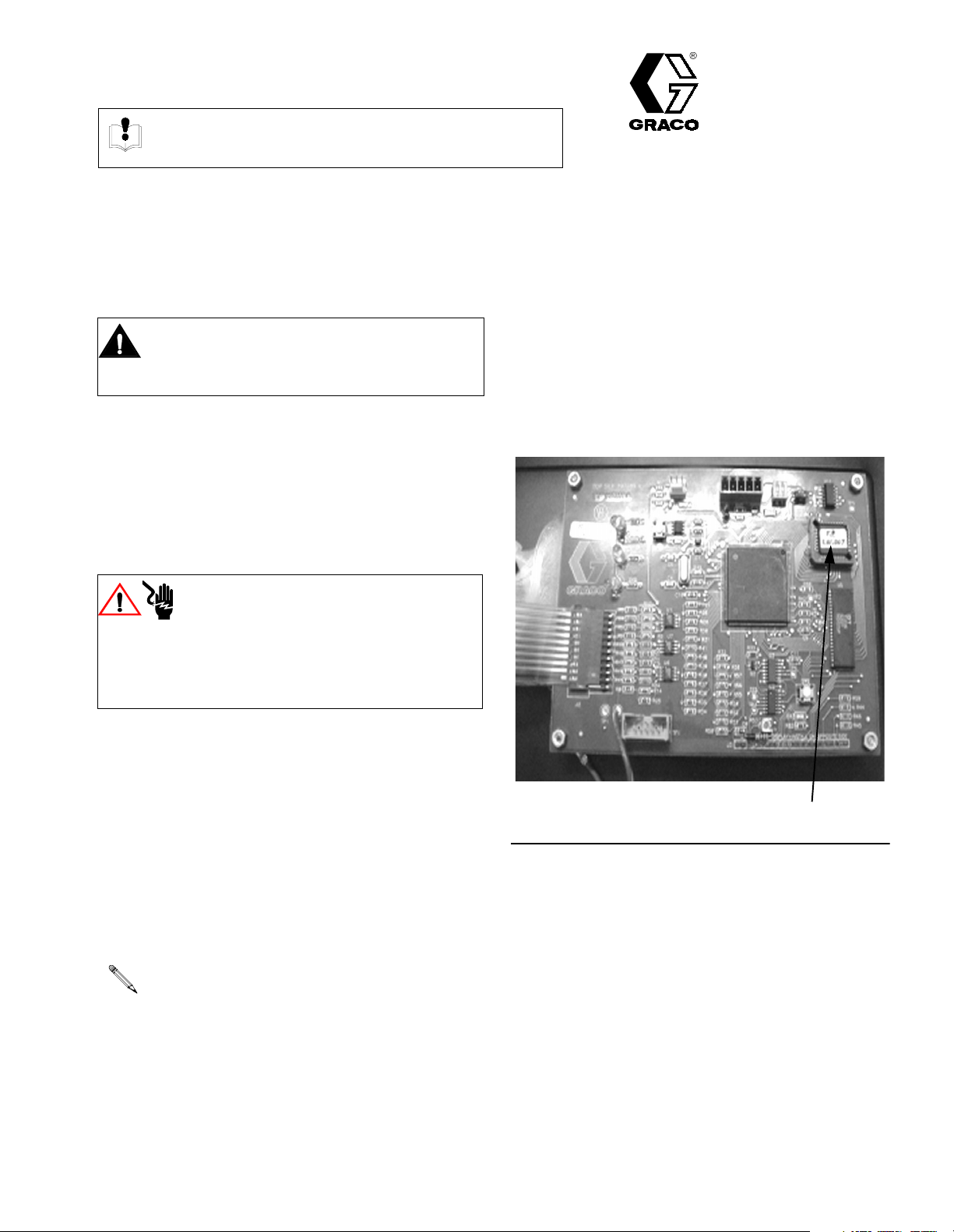
3. Locate PCB chip (B) on display circuit board. See
.
. 1
F
IG
4. Remove old PCB chip (B) with chip extractor pro-
vided.
The chip has three sharp corners and one
chamfered corner. Orient the chip’s chamfered
corner toward the socket’s chamfered corner.
Incorrect installation can damage the chip or
board.
or 309301 (ProBatch™) and refer to
COPYRIGHT 2001, Graco Inc.
Graco Inc. is re
istered to I.S. EN ISO 9001
FIG. 1
Page 2

A
B
ProBatch Controller
TI1089A
A
FIG. 2
B
ProDispense Controller
Sales Offices:
International Offices:
Minneapolis, Detroit
Belgium, Korea, Hong Kong, Japan
GRACO INC. P.O. BOX 1441 MINNEAPOLIS, MN 55440-1441
www.graco.com
PRINTED IN USA 309396 July 2001
TI1436a
 Loading...