

Page 1
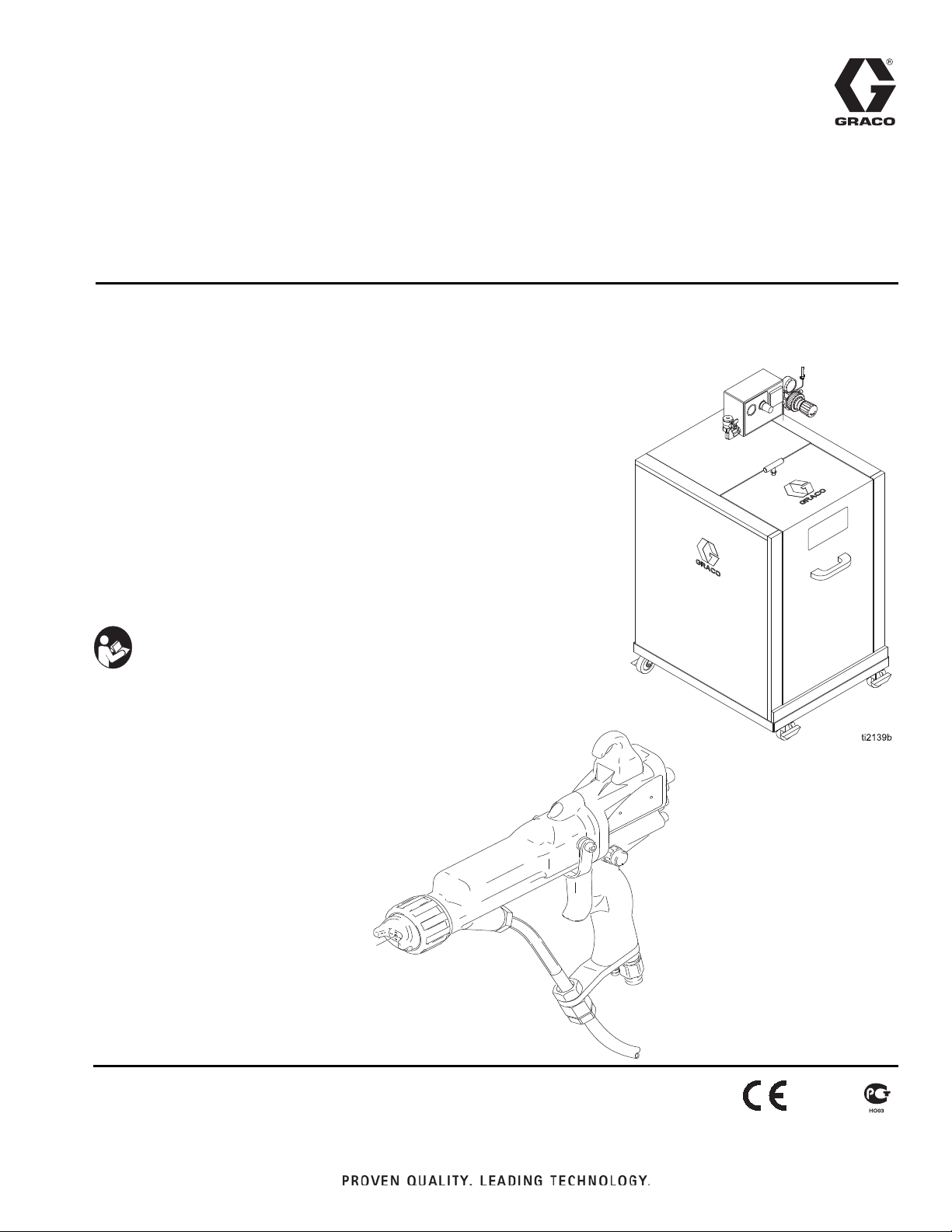
WB 100
Isolation Enclosure
PRO Xs3
Smart Gun
and Fluid
Instructions/Parts List
ELECTROSTATIC, WATERBORNE, AIR SPRAY
WB100 Isolation System and PRO™
Xs3 Spray Gun
For use when electrostatically spraying conductive, waterborne fluids that meet at least one of the
following conditions for non-flammability. For professional use only.
FM Approved
• The fluid has a flash point above 140F (60C) and a maximum
organic solvent concentration of 20%, by weight, per ASTM Standard D93.
• The fluid does not sustain burning when tested per
ASTM Standard D4206 Sustained Burn Test.
CE-EN 50059 Compliant
• Materials which cannot be ignited, in any mixture with air,
by an energy source of less than 500 mJ.
Important Safety Instructions
Read all warnings and instructions in this manual.
Save these instructions.
309293N
EN
100 psi (0.7 MPa, 7 bar) Maximum Air Inlet Pressure
100 psi (0.7 MPa, 7 bar) Maximum Working Fluid Pressure
See page 3 for a List of Models
For patent information, see www.graco.com/patents.
TI1681A
Page 2

Table of Contents
List of Models . . . . . . . . . . . . . . . . . . . . . . . . . . . . . 3
Symbols . . . . . . . . . . . . . . . . . . . . . . . . . . . . . . . . . . 4
Warning Symbol . . . . . . . . . . . . . . . . . . . . . . . . . 4
Caution Symbol . . . . . . . . . . . . . . . . . . . . . . . . . . 4
Warning . . . . . . . . . . . . . . . . . . . . . . . . . . . . . . . . . . 4
Warning . . . . . . . . . . . . . . . . . . . . . . . . . . . . . . . . . . 6
Introduction . . . . . . . . . . . . . . . . . . . . . . . . . . . . . . . 7
How the Electrostatic Air Spray Gun Works . . . . 7
Spraying Waterborne Fluids Electrostatically . . . 7
Gun Overview . . . . . . . . . . . . . . . . . . . . . . . . . . . 8
Installation . . . . . . . . . . . . . . . . . . . . . . . . . . . . . . . . 9
System Requirements . . . . . . . . . . . . . . . . . . . . . 9
Warning Sign . . . . . . . . . . . . . . . . . . . . . . . . . . . 9
Install the System . . . . . . . . . . . . . . . . . . . . . . . . 9
Ventilate the Spray Booth . . . . . . . . . . . . . . . . . 11
Connect the Air Line . . . . . . . . . . . . . . . . . . . . . 11
Ground the Cabinet . . . . . . . . . . . . . . . . . . . . . . 11
Connect the Waterborne Fluid Hose . . . . . . . . . 11
245895 Agitator Kit . . . . . . . . . . . . . . . . . . . . . . 14
245944 Fluid Regulator Kit . . . . . . . . . . . . . . . . 15
Select a Fluid Nozzle and Air Cap . . . . . . . . . . 16
Grounding . . . . . . . . . . . . . . . . . . . . . . . . . . . . . 17
Check Electrical Grounding . . . . . . . . . . . . . . . 18
Operation . . . . . . . . . . . . . . . . . . . . . . . . . . . . . . . . 19
Operating Checklist . . . . . . . . . . . . . . . . . . . . . . 19
Fluid Voltage Discharge and Grounding Procedure
20
Pressure Relief Procedure . . . . . . . . . . . . . . . . 20
Fill the Fluid Supply . . . . . . . . . . . . . . . . . . . . . . 21
Adjust the Spray Pattern . . . . . . . . . . . . . . . . . . 21
Shutdown . . . . . . . . . . . . . . . . . . . . . . . . . . . . . 25
Low Voltage Adjustment (Smart Guns Only) . . 25
Maintenance . . . . . . . . . . . . . . . . . . . . . . . . . . . . . . 26
Flush the Spray Gun . . . . . . . . . . . . . . . . . . . . . 26
Daily Care and Cleaning . . . . . . . . . . . . . . . . . . 27
Clean the Air Cap and Fluid Nozzle . . . . . . . . . 29
Grease Door Latch Threads . . . . . . . . . . . . . . . 29
Electrical Tests . . . . . . . . . . . . . . . . . . . . . . . . . . . 30
Test Gun Resistance . . . . . . . . . . . . . . . . . . . . 30
Test Power Supply Resistance . . . . . . . . . . . . . 31
Test Electrode Resistance . . . . . . . . . . . . . . . . 32
Test Ground Strip Resistance . . . . . . . . . . . . . . 33
Test Cylinder Resistance . . . . . . . . . . . . . . . . . 33
Troubleshooting . . . . . . . . . . . . . . . . . . . . . . . . . . . 34
Voltage Loss Troubleshooting . . . . . . . . . . . . . . 34
Spray Pattern Troubleshooting . . . . . . . . . . . . . 37
Gun Operation Troubleshooting . . . . . . . . . . . . 38
Electrical Troubleshooting . . . . . . . . . . . . . . . . . 39
Repair . . . . . . . . . . . . . . . . . . . . . . . . . . . . . . . . . . . 41
Prepare the Gun for Service . . . . . . . . . . . . . . . 41
Air Cap/Nozzle Replacement . . . . . . . . . . . . . . 42
Electrode Replacement . . . . . . . . . . . . . . . . . . . 43
Fluid Packing Removal . . . . . . . . . . . . . . . . . . . 44
Packing Rod Repair . . . . . . . . . . . . . . . . . . . . . . 45
Barrel Removal . . . . . . . . . . . . . . . . . . . . . . . . . 46
Barrel Installation . . . . . . . . . . . . . . . . . . . . . . . . 46
Power Supply Removal and Replacement . . . . 47
Turbine Alternator Removal and Replacement . 48
Fan Air Adjustment Valve Repair . . . . . . . . . . . 49
Fluid Adjustment Valve Repair . . . . . . . . . . . . . 50
Air Valve Repair . . . . . . . . . . . . . . . . . . . . . . . . . 50
Atomizing Air Restrictor Valve Removal and
Replacement . . . . . . . . . . . . . . . . . . . . . . . . 51
ES ON/OFF Valve Repair . . . . . . . . . . . . . . . . . 51
Parts . . . . . . . . . . . . . . . . . . . . . . . . . . . . . . . . . . . . 52
Accessories . . . . . . . . . . . . . . . . . . . . . . . . . . . . . . 65
Air Line Accessories . . . . . . . . . . . . . . . . . . . . . 65
Fluid Line Accessories . . . . . . . . . . . . . . . . . . . . 65
Gun Accessories . . . . . . . . . . . . . . . . . . . . . . . . 66
Miscellaneous Accessories . . . . . . . . . . . . . . . . 66
Technical Specifications . . . . . . . . . . . . . . . . . . . . 69
California Proposition 65 . . . . . . . . . . . . . . . . . . . 69
Graco Standard Warranty . . . . . . . . . . . . . . . . . . . 70
Graco Information . . . . . . . . . . . . . . . . . . . . . . . . . 70
2 309293N
Page 3

List of Models
Part No. Gun Model Description
245897 PRO Xs3 Waterborne Isolation Enclosure with standard electrostatic air
245898 PRO Xs3 Waterborne Isolation Enclosure with smart electrostatic air
233825 Waterborne Isolation Enclosure without hoses and gun.
List of Models
FM Approved
spray gun, grounded air hose, and shielded waterborne fluid
hose
spray gun, grounded air hose, and shielded waterborne fluid
hose
244581,
Series B
245301, PRO Xs3 Part No. 244581 Gun, with 25 ft (7.6 m) waterborne fluid hose
244582,
Series B
245305 PRO Xs3 Part No. 244582 Gun, with 25 ft (7.6 m) waterborne fluid hose
245252 Shielded Waterborne Fluid Hose Assembly 25 ft (7.6 m)
PRO Xs3 Standard Electrostatic Air Spray Gun, for waterborne coatings
PRO Xs3 Smart Electrostatic Air Spray Gun, for waterborne coatings,
EN 50059 Compliant
244581,
Series B
244582,
Series B
246511 Waterborne Isolat ion Enclosure, without hoses and gun
246431 PRO Xs3 Unshielded Waterborne fluid hose assembly, 25 ft (7.6 m).
246592 PRO Xs3 Waterborne Isolation Enclosure with standard electrostatic air
PRO Xs3 Standard Electrostatic Air Spray Gun, for waterborne coatings.
PRO Xs3 Smart Electrostatic Air Spray Gun, for waterborne coatings.
spray gun, grounded air hose, and unsh ielded waterborne flu id
hose
246593 PRO Xs3 Waterborne Isolation Enclosure with smart electrostatic air
spray gun, grounded air hose, and unsh ielded waterborne flu id
hose
309293N 3
Page 4
Symbols
WARNING
CAUTION
Symbols
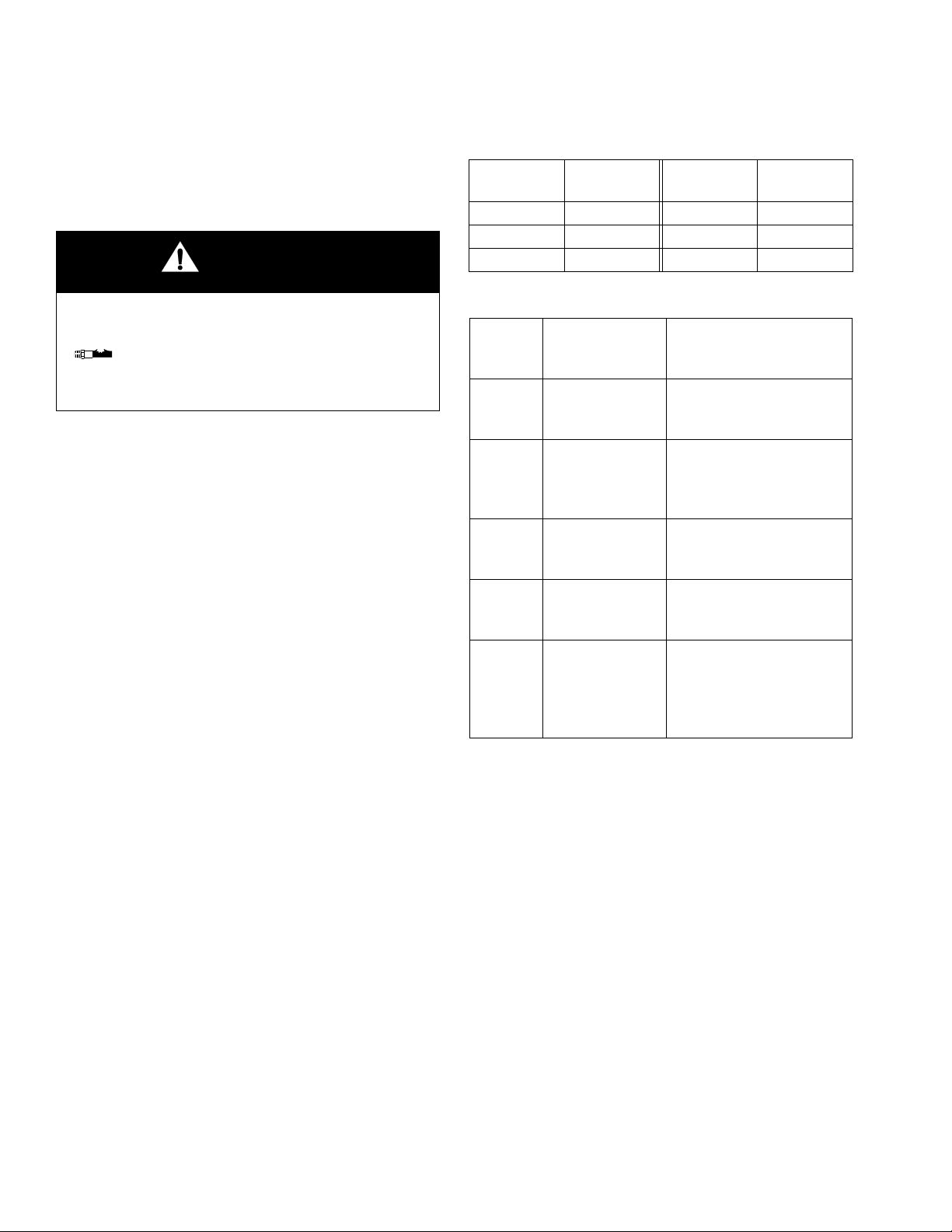
Warning Symbol
This symbol alerts you to the possibility of serious injury
or death if you do not follow the instructions.
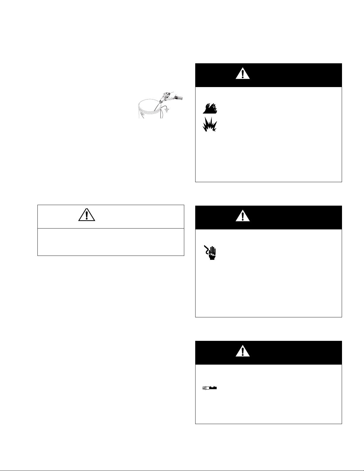
WARNING
Electric Shock Hazard
Improper grounding, setup, or usage of an isolated waterborne system can cause a hazardous
condition and result in electric shock or other serious injury.
• Ground the equipment, all personnel in or close to the spray area, the object being sprayed,
and all conductive objects in the spray area. See Grounding, page 17.
• The gun must be connected to a voltage isolation system that will discharge the system voltage when the gun is not in use.
• All components of the isolation system that are charged to high voltage must be contained
within an enclosure that prohibits personnel from making contact with the high voltage components before the system voltage is discharged.
Caution Symbol
This symbol alerts you to the possibility of damage to or
destruction of equipment if you do not follow the instructions.
• Follow the Fluid Voltage Discharge and Grounding Procedure on page 20 when inst ructed
to discharge the voltage; before cleaning, flushing, or servicing the system; before approaching the front of the gun; and before opening the safety enclosure for the isolated fluid supply.
• Do not touch the gun nozzle or come within 4 in. (102 mm ) of th e no zzle du rin g gu n op erat ion
or for 30 seconds after operation stops, to allow the voltage to discharge through the bleed
resistor. Place the gun in the holster (accessor y) du rin g this 30 seco nd pe rio d. Refe r to Fluid
Voltage Discharge and Grounding Procedure, page 20.
• Electrically connect a metal part of the fluid supply unit to the bleed resistor.
• The gun air supply must be interlocked with the isolat ion system to shut off the air supply any-
time the isolation system enclosure is opened.
• Use only the red-colored Graco electrically conductive gun air hose with this gun. Do not use
black or grey-colored Graco air hoses.
• Install only one continuous Graco waterborne flu id h ose bet ween the isol at ed f lu id sup ply and
the spray gun. Do not splice hoses together.
• Do not enter a high voltage or hazardous area until all high voltage equipment has been discharged.
4 309293N
Page 5
Warning
WARNING
Fire and Explosion Hazard
Improper grounding, poor air ventilation, ope n flam es, or sp ar ks can cause a hazardou s co ndit ion
and result in a fire or explosion.
• Electrostatic equipment must be used only by trained, qualified personnel who understand the
requirements in this manual.
• Ground the equipment, all personnel in or close to the spray area, the object being sprayed,
and all other electrically conductive objects in the spray area. See Grounding, page 17.
• Check gun resistance daily. See Test Gun Resistance on page 30.
• If there is any static sparking while using the equipment, st op spraying i mmediately. Identi fy
and correct the problem.
• Provide fresh air ventilation to avoid buildup of flammable or toxic vapors. See Ventilate the
Spray Booth on page 11.
• Only use this equipment to spray non-flammable, waterborne fluids, as defined on the front
cover of this manual.
• Only flush, purge, or clean the electrostatic waterborne spray system with non-flammable fluids, as defined on the front cover of this manual.
• Do not flush with the gun electrostatics turned on.
• Keep the spray area free of debris and rags. Do not store solvent and flammable fluids in the
spray area.
• Eliminate all ignition sources such as pilot lights, cigarettes, and static arcs from plastic drop
cloths. Do not plug in or unplug power cords or turn lights on or off in the spray area.
• Use only non-sparking tools to clean residue from the booth and hangers.
Toxic Fluid Hazard
Hazardous fluids or toxic fumes can cause a serious injury or death if splashed in the eyes or on
the skin, swallowed, or inhaled.
• Know the specific hazards of the fluid you are using. Read the fluid manufacturer’s warnings.
• Store hazardous fluid in an approved container. Dispo se of the hazardous fl uid according to all
local, state, and national guidelines.
• Wear appropriate protective clothing, gloves, eyewea r, and respirator.
309293N 5
Page 6
Warning
WARNING
Equipment Misuse Hazard
Equipment misuse can cause the equipment to rupture, malfunction, or start unexpectedly and
result in a serious injury.
• This equipment is for professional use only.
• Read all manuals, tags, and labels before operating the equipment.
• Use the equipment only for its intended purpose. If you are uncertain, call your Graco distribu-
tor.
• Do not alter or modify equipment. Use only genuine Graco parts and accessories.
• Do not operate the power supply above 60 kV. Use only Graco Part No. 2 44542 Power Supply
with this gun.
• Check the equipment daily. Repair or replace worn or damaged parts immediately.
• Do not exceed the maximum working pressure of the lowest rated system component. Maxi-
mum working air and fluid pressure of this equipment is 100 psi (0.7 MPa, 7.0 bar).
• Use fluids and solvents that are compatible with the equipment wetted parts. See the Techni-
cal Specifications section of all equipment manuals. Read the fluid and solvent manufac-
turer’s warnings.
• Route the hoses away from traffic areas, sharp edges, moving parts, a nd h ot surfaces. Do no t
expose Graco hoses to temperatures above 180F (82C) or below -40F (- 40C).
• Wear hearing protection when operating this equipment.
• Comply with all applicable local, state, and national fire, electrical, and other safety regula-
tions.
Pressurized Equipment Hazard
Spray from the gun, hose leaks, or ruptured compone nts can splash fluid in the e yes or on the skin
and cause serious injury.
• Do not point the spray gun at anyone or at any par t of the body.
• Do not stop or deflect fluid leaks with your hand, body, glove, or rag.
• Follow the Pressure Relief Procedure, page 20, when you stop spraying and before cleanin g,
checking, or repairing equipment.
• Check hoses and couplings daily. Replace worn, damaged, or loose parts immediately.
• Tighten all fluid connections before each use.
6 309293N
Page 7

Introduction
How the Electrostatic Air Spray Gun Works
Introduction
The air hose supplies air to the spray gun. Part of the ai r
operates the turbine and the rest of t he a ir a to mizes the
fluid being sprayed. The turbine generates power, which
is converted by the power cartridge to supply high voltage current to the gun’s electrode.
The fluid source supplies fluid t o the h ose a nd g un. The
gun must be connected to a voltage isolation system to
maintain voltage at the gun. In an isolation system, the
entire fluid supply is electrostatically charged. The
charged fluid is attracted to the grounded workpiece,
wrapping around and evenly coating all surfaces.
Spraying Waterborne Fluids Electrostatically
This electrostatic air spray gun is designed to spray only
waterborne fluids with a flash point above 140 F (60C)
and a maximum organic solvent concentration of 20%,
by weight, per ASTM Standard D93. Also, the fluid must
not sustain burning when tested per ASTM Standard
D4206 Sustained Burn Test.
CAUTION
The Graco warranty is void if the spray gun is connected to a non-Graco voltage isolation system or if
the gun is operated above 60 kV.
When connected to a voltage isolation system, all of the
fluid in the spray gun, fluid hose, and isolat ed fluid supply is charged to high voltage, which means that the system has more electrical energy than a solvent-based
system. Therefore, only non-flammable fluids (as
defined on the front cover of this manual) can be
sprayed with the system or be used to clean, flush, or
purge the system.
Precautions must be taken when using electrostatic
waterborne equipment to avoid potential shock haza rds.
When the spray gun charges the isolated fluid to high
voltage, it is similar to charging a capacitor or a battery.
The system will store some of the energy while spraying
and retain some of that energy after the spray gun is
shut off. It is not safe to touch the front end of the gun
until the stored energy is discharged. The amount of
time it takes to discharge the energy depends on the
system design. Follow the Fluid Voltage Discharge
and Grounding Procedure on page 20 before
approaching the front of the gun.
309293N 7
Page 8
Introduction
TI1681A
I O
ti1266a
I O
ES
FLUID
LO VOLTAGE
ES HI/LO
DISPLAY
ES INDICATOR
ES ON/OFF
RESTRICTOR
AIR
RESTRICTOR
FLUID
ES ON/OFF
AIR
Standard Model Smart Model
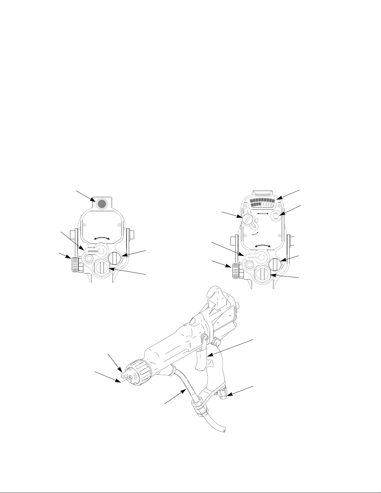
TRIGGER
AIR INLET
FLUID TUBE
AIR CAP
ELECTRODE
Gun Overview
The electrostatic gun includes the following controls
IG. 1.).
(see F
• FLUID adjustment valve. Adjusts flu id rod travel.
Use only in low flow conditions, to reduce wear.
• Fan AIR adjustment valve. Adjusts fan size and
shape.
• Atomizing air RESTRICTOR valve. Restricts
atomizing air flow. Replace with plug (included) if
desired.
• ES ON/OFF valve. Turns electrostatics ON (I) or
OFF (0).
• ES INDICATOR (standard gun only). Green when
ES is ON (I).
• Voltage/current DISPLAY (smart models only).
Shows voltage (V) and current (A). Green=spray,
yellow/red=see Electrical Troubleshooting, page
39.
• ES HI/LO switch (smart models only). Sets volt-
age to HI or LO (factory settings).
• LO VOLTAGE adjustment (smart models only).
Remove plug to adjust to four settings. Page 21.
100
%
0
KV
μα
HI
LO
ES
ES
I O
ti1253a
Fig. 1. Gun Overview
8 309293N
Page 9
Installation
Installation
System Requirements
A safe, well designed voltage isolation system should
have the following features:
• All components of the isolation system that are
charged to high voltage must be contained within an
enclosure that prohibits persons from making contact with the high voltage components before the
system voltage is discharged.
• A bleed resistor to drain off the system voltage when
the spray gun is not in use.
• The system should not have any severe arcing
occurring when the isolation mechanism opens and
closes. Severe arcing will shorten the life of the system components.
• The system must include a means for automatically
discharging the system voltage when anyone opens
the isolation enclosure.
CAUTION
Install the System
WARNING
Fire, Explosion, and Electric Shock Hazard
Installing and servicing this equipment
requires access to parts which may cause
electric shock or other serious injury if work
is not performed properly.
•Do not install or service this equipment
unless you are trained and qualified.
•Be sure your installation complies with all
National, State and Local safety and fire
codes, NFPA 33, NEC 504 and 516, and
OSHA standard 1910.107.
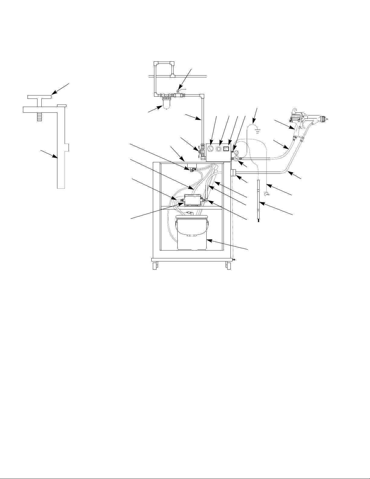
FIG. 2. on page 10 shows a PRO Xs electrostatic waterborne air spray system. For assistance in designing a
system to suit your particular needs, contact your Graco
distributor.
The Graco warranty is void if the spray gun is connected to a non-Graco voltage isolation system or if
the gun is operated above 60 kV.
Warning Sign
Mount the warning sign, Part No. 186118, in the spr ay
area where it can be seen and read by all operators.
Additional warning signs are available at no charge.
309293N 9
Page 10
Installation
A
B*
DE
F
H
J
K*
L
M
N
P*
Q*
R
S
T
U
V*
C
G
Gun ES ON/OFF valve: I is ON, 0 is OFF
B*
BB
AA
Y
Z
X
W
TI1775C
TI1896C
Fig. 2. Typical Installation: PRO Xs Waterborne System
Key
A Main Air Supply Line
B* Main Air Supply Shutoff Valve (bleed-type)
C Pump Air Pressure Gauge
D Pump Air Pressure Regulator
EkV Meter
FPump
G Pump Suction Hose
H Paint Container
J Bleed Resistor
K* Enclosure Safety Interlock
L Isolated Enclosure
M Gun Air Line Filter
N Gun Air Pressure Regulator
P* Graco Red Grounded Air Supply Hose
Q* Air Hose Ground Wire
R Graco Waterborne Fluid Hose
S Waterborne Electrostatic Air Spray Gun
T Grounding Rod
U Ground Terminal
V* Main Ground Wire
W Strain Relief/Ground Fitting
X Pump Air Supply Line
Y Grounding Cylinder
Z Pump Fluid Outlet Fitting
AA Isolated Enclosure Door
BB Enclosure T-Handle Locking Screw
* Required for safe operation. Must be purchased separately.
10 309293N
Page 11
Installation
Ventilate the Spray Booth
WARNING
Flammable or Toxic Vapor Hazard
Provide fresh air ventilation to avoid the
buildup of flammable or toxic vapors. Do not
operate the gun unless ventilation fans are
operating.
Check and follow all National, State, and Local codes
regarding air exhaust velocity requirements.
NOTE: High velocity air exhaust will decrease the operating efficiency of the electrostatic system. The minimum allowable air exhaust velocity is 60 linear ft/min
(18.3 linear meters/minute).
Connect the Air Line
4. Connect the main air supply line (A) to the
bleed-type air valve (B). The bleed valve shuts off all
air to the system. Install an additional bleed-type air
valve (B) upstream of the air filter (M) to isolate the
filter for servicing.
WARNING
Pressurized Equipment Hazard
The bleed-type air valve (B) is required in
your system to relieve air trapped between
the valve and the fluid supply unit after the
air regulator (D) is shut off. Trapped air can cause the
fluid supply unit to cycle unexpectedly, which can
result in serious injury, including splashing fluid in the
eyes or on the skin.
Ground the Cabinet
Connect the main ground wire (V) to a true earth
ground.
WARNING
Electric Shock Hazard
To reduce the risk of electric shock or other
serious injury, you must use the red-colored
Graco Electrically Conductive Air Hose for
the gun air supply hose, and you must connect the hose ground wire to a true earth ground. Do
not use the black or grey-colored Graco air hoses.
1. Install an air line filter/water separator (M) on the
main air supply line to ensure a dry, clean air supply
to the gun. Dirt and moisture can ruin the appearance of your finished workpiece and can cause the
gun to malfunction.
2. Install a bleed-type air regulator (N) on the gun air
line (P).
3. Connect the red-colored Graco Grounded Air Supply Hose (P) between the gun air regulator (N) and
the gun's air inlet. The gun air inlet fitting has a
left-hand thread. Connect the air supply hose
ground wire (Q) to a true earth ground.
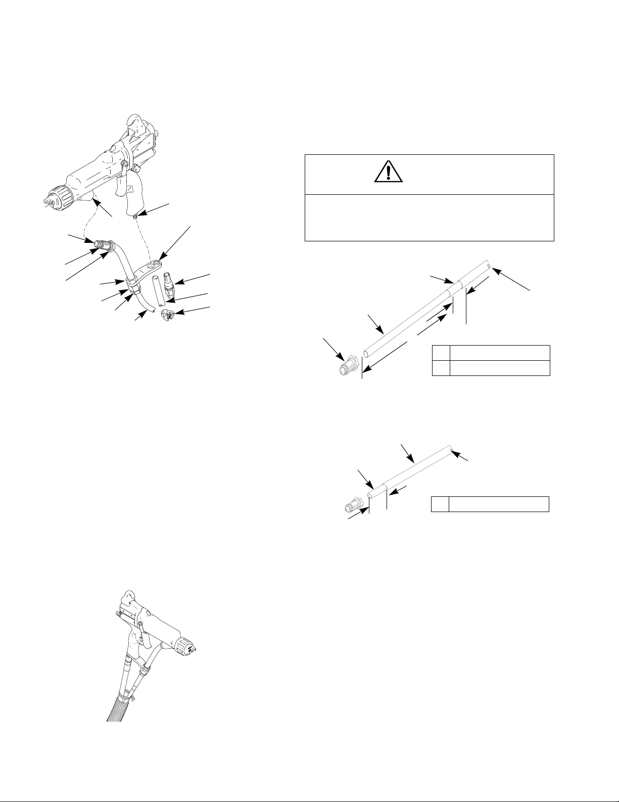
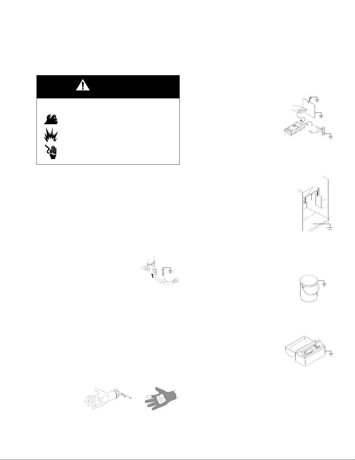
Connect the Waterborne Fluid Hose
Always use a Graco waterborne fluid hose between the
voltage isolation system fluid outlet and the gu n fluid
inlet. See F
sists of an inner PTFE tube (T) and an abrasion-resistant outer jacket (J). Shielded hose 245252 also has a
conductive layer (C), The conductive layer is con nected
to ground at the gun fitting bracket (104).
Before connecting the waterbor ne fl uid hose to t he gu n,
blow it out with air and flush with water to remove contaminants. Flush the gun before using it.
IG. 3.. The waterborne fluid hose (101) con-
WARNING
Electric Shock Hazard
To reduce the risk of electric shock, install
only one continuous Graco waterborne
hose between the isolated fluid supply and
the gun. Do not splice hoses together.
309293N 11
Page 12
Installation
35
38
39
101
102
103
104
105
107
106
108
16
A
TI2155b
TI21188a
F
T
A
B
A 7.40 in. (188 mm)
B 2.0 in. (50 mm)
C
J
Shielded Hose 245252
T
C
A 1.25 in (32 mm)
J
A
TI2742A
Unshielded
Hose 246431
1. Remove the gun air inlet fitting (35). See FIG. 3.
Fig. 3. Connect the Fluid Hose
NOTE: In a shielded hose system, if a hose failure
occurs where high voltage arcs through the inner tube,
voltage will be discharged to ground through the conductive hose layer. When properly installed, the conductive hose layer is grounded through its connection to the
grounded enclosure.
2. For the fluid hose to fit properly, it must be stripped
and assembled to the dimensions in F
IG. 5. Push
the inner tube (T) into the fitting (F) until the tube
bottoms. A new Graco waterborne fluid hose comes
fully assembled to these dimensions.
CAUTION
Be careful not to cut into the inner tube (T) of the
hose when stripping the hose. Nicks or cuts in the
PTFE tube will cause premature hose failure.
Fig. 5. Waterborne Hose Dimensions (At Gun)
Using unshielded fluid hoses minimizes the system
capacitance, resulting in faster response times and a
large reduction in the energy stored in the system, as
compared to shielded hoses. However, without the
ground shield, a weak static charge can occasionally
build up on the outer surface of the hose. To minimize
any static charge felt on the hose surface, bundle t he air
and fluid hose together, and wrap with a pr otective
cover, as shown in F
Fig. 4. Bundling the Air and Fluid Hoses
12 309293N
IG. 4.
Fig. 6.
3. Generously apply dielectric grease (40) to the o-ring
(107) and the threads of the fitting (106). Pull the fitting back 1-1/2 in. (38 mm) and apply grease to the
exposed PTFE hose to fill the area between the
hose and the fitting. Make sure the barrel inlet is
clean and dry, then screw the fitting into the fluid
inlet of the gun barrel (16). See F
IG. 3.
4. Loosen the strain relief nut (102) so the br acket can
move freely on the hose.
5. Align the bracket (104) holes with the air inlet and
exhaust outlet. Secure with the air inlet fitting (35).
Tighten the strain relief nut (102) to secure the hose.
Page 13
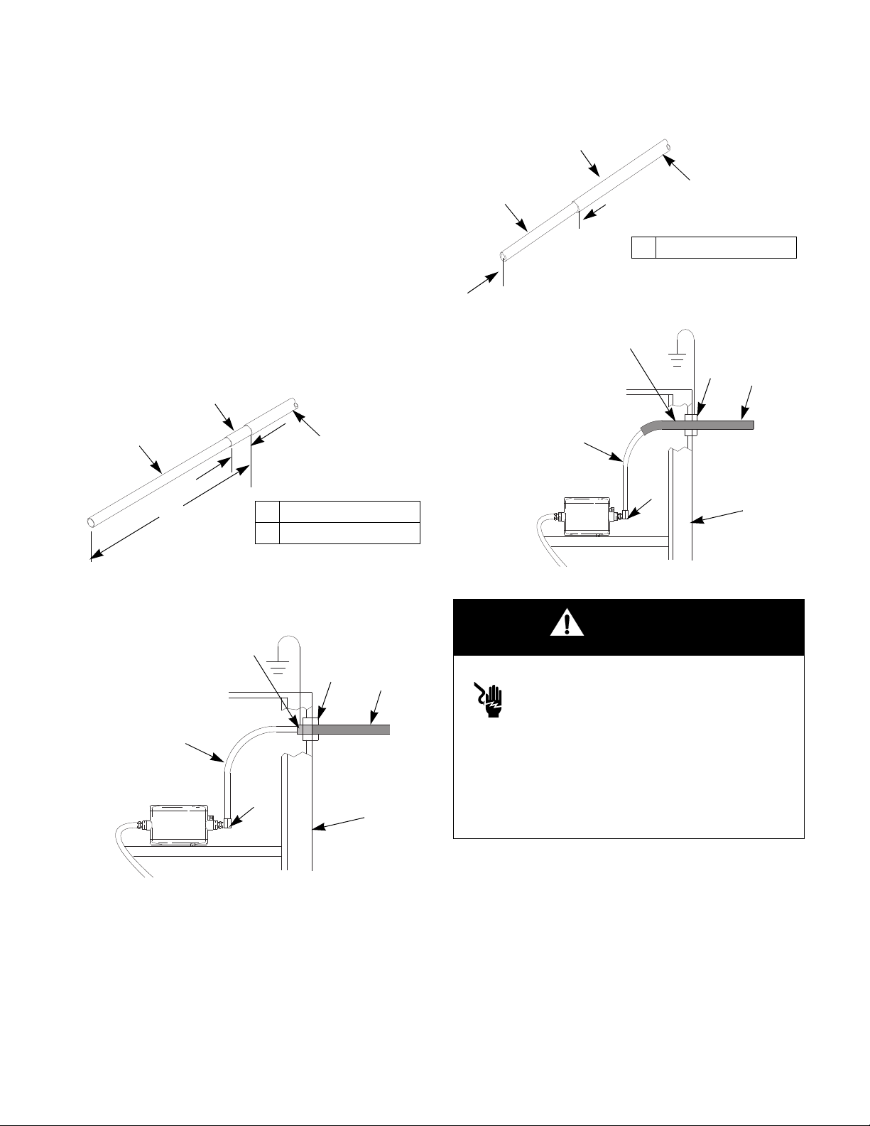
6. Check that the nut (105) is tightened securely to th e
T
C
A 14.5 in. (368 mm)
B 0.75 in. (19 mm)
J
A
B
TI2166A
Shielded
Hose 245252
T
C
J
W
Z
L
See Warning at right.
T
C
A 12.0 in (305 mm)
J
A
TI2743A
Unshielded
Hose 246431
T
C
J
W
Z
L
See Warning below.
TI2744
A
ferrule housing (103).
7. Press the exhaust tube (38) onto the barbed
adapter (A). Secure with the clamp (39).
8. Connect the other end of the hose to the isola ted
fluid supply as follows:
a. Graco WB100 Enclosure: Slide hose through
the strain relief fitting (W). Ensure conductive
layer (C) has passed through fitting. Tighten to
55 in-lb (6.2 N•m). Pull back on hose to check it
is secure. Comply with the requirements in
Warning at right. See F
IG. 7. and FIG. 8..
Installation
Fig. 9.
Fig. 7. Waterborne Hose Dimensions (At Graco
WB100 Enclosure)
Fig. 8. Shielded Fluid Hose Connection at Graco
WB100
309293N 13
Fig. 10. Unshielded fluid connection
WARNING
Electric Shock Hazard
For Shielded hose systems:
Conductive hose layer (C) must be
grounded through its connection to the iso-
lation system’s grounded enclosure (L) or
grounded safety fence. To maintain grounding continuity, the conductive hose layer (C) must be engag ed
in the ferrule when the strain relief nut is tightened.
Failure to properly install the hose in the strain relief
could result in an electric shock.
TI1897A
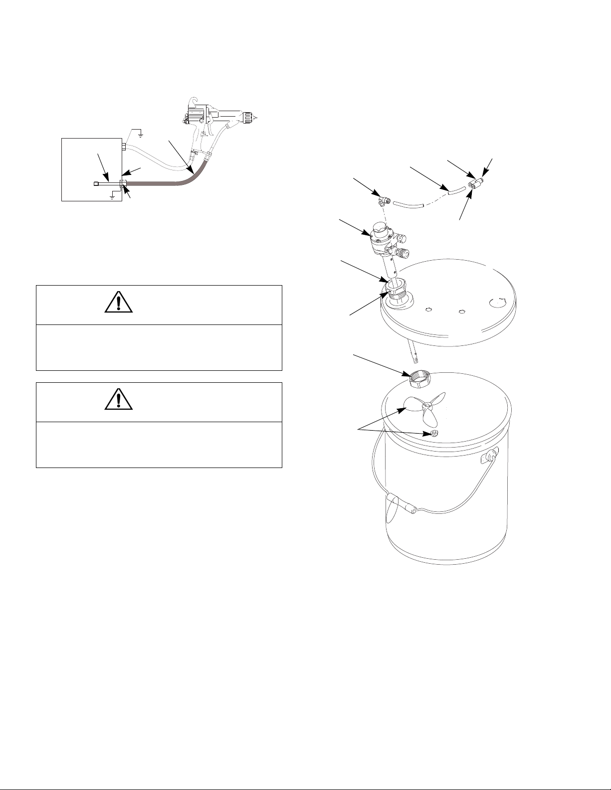
b. Non-Graco Isolated Enclosure: Connect hose
as instructed in the isolation system manual,
and comply with the requirements in the Warn-
ing at right. Refer to F
IG. 11..
Page 14
Installation
T
J
L
C (see note above)
NOTE: Ground layer (C) of hose must
be grounded at isolation system.
401
406
403
404
406 (Ref)
407
402
TI2137A
Install tube A2 here
Connect to elbow (282)
inside control box (258)
408
TI1966A
Fig. 11. Shielded Fluid Hose Connection at Non-Graco Isolated Enclosure
c. Connect the end of the tube (T) to the pump
fluid outlet fitting (Z).
CAUTION
7. Assemble the other parts of the kit as shown.
Secure the agitator with the setscrew (408).
8. Return the system to service.
The Graco warranty is void if the spray gun is connected to a non-Graco voltage isolation system or if
the gun is operated above 60 kV.
CAUTION
Factory Mutual approval is valid only when this gun is
used with Factory Mutual approved voltage isolation
systems.
245895 Agitator Kit
To add an agitator to the Graco isolation system, order
Part No. 245895. See page 67 for the kit parts list.
1. Discharge the system voltage (page 20).
2. Relieve the pressure (page 20).
3. Open the isolated enclosure door.
Fig. 12. 245895 Agitator Kit
4. Remove the back of the control box (258).
5. Remove tube (A2) from elbow (282) at the air manifold; see the tubing diagram on page 64. Install the
Y fitting (402) into the elbow. Install tubes (A2) and
(407) into the Y fitting. See F
tor tube (407) into the cabinet.
6. Replace the back of the control box (258).
14 309293N
IG. 12.. Route the agita-
Page 15
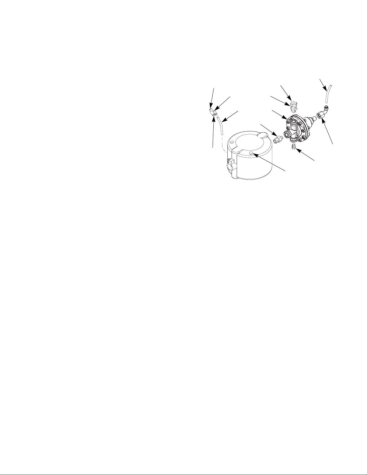
245944 Fluid Regulator Kit
TI2149A
501
502
503
504
505
506
507
Connect
tube A2
here
S
Tube A1
Connect water-
borne fluid
hose here
Connect to elbow (282) inside control
box (258)
To add a fluid regulator to the Graco isolation system,
order Part No. 245944. See page 68 for the kit parts list.
1. Discharge the system voltage (page 20).
2. Relieve the pressure (page 20).
3. Open the isolated enclosure door.
4. Remove the 1/4 OD tube (A1) from the pump air
inlet; see the tubing diagram on page 64.
5. Remove the waterborne fluid hose from the pump
fluid outlet fitting (231) and remove the fittin g.
Installation
6. Unscrew the two pump mounting screws (S, F
IG.
13.) and remove the pump from the isolation enclosure.
7. Remove the back of the control box (258).
8. Remove tube (A2) from elbow (282) at the air manifold; see page 64. Install the Y fitting (506) in the
elbow. Install tubes (A2) and (507) into the Y fitting.
Route the tube (507) into the cabinet.
9. Replace the back of the control box (258).
10. Assemble the fluid regulator kit as shown in F
IG. 13..
11. Reinstall the pump in the isolation enclosu re. U se
the two mounting holes to the left of the holes used
previously, to allow clearance for the fluid regulator.
12. Connect tube (A1) to the air inlet of fluid regulator
(504). Connect tube (507) to the pump air inlet.
13. Connect the waterborne fl uid hose to the fluid regulator outlet fitting (501).
Fig. 13. Fluid Regulator Kit
14. Return the system to service.
NOTE: The cabinet air regulator and gauge (216, 217)
will now operate the air piloted fluid regulator (504). The
pump will now operate at the inlet air pressure.
309293N 15
Page 16
Installation
Select a Fluid Nozzle and Air Cap
WARNING
Pressurized Equipment Hazard
To reduce the risk of an injury, follow the
Pressure Relief Procedure on page 20
before removing or installing a fluid nozzle
and/or air cap.
The gun is supplied with Part No. 197266 Nozzle and
24A276 Air Cap. If you require a different size, refer to
Table 1 and Table 2 , and instruction manual 309419, or
consult with your Graco distributor. See Air Cap/Nozzle
Replacement on page 42.
A wide pattern kit (P/N 24A431) is included with the gun
and if installed, will provide fan air for wider spray patterns. (If pattern becomes split, use the fan air valve to
reduce the amount of fan air.)
Table 1: Fluid Nozzles
Part No.
197263 0.75 (.030) 197266 1.5 (.055)
197264 1.0 (.042) 197267 1.8 (.070)
197265 1.2 (.047) 197268 2.0 (.080)
Size,
mm (in.)
Part No.
Size,
mm (in.)
Table 2: Air Caps
Part No.
24A438
24A279
24A376*
24A274
24A439
Pattern Shape
and Length in.
(mm)
Round end;
15-17 (381-432)
Round end;
14-16 (356-406)
Tapered end;
17-19 (432-483)
Tapered end;
12-14 (305-356)
Round end;
11-13 (279-330)
Recommended Fluids and
Production Rates
Light to medium viscosity.
Up to 15 oz/min (450
cc/min)
Medium to high viscosity
and high solids.
Up to 15 oz/min (450
cc/min)
Light to medium viscosity.
Up to 15 oz/min (450
cc/min)
Light to medium viscosity.
Up to 15 oz/min (450
cc/min)
Medium to high viscosity
and high solids.
Up to 15 oz/min (450
cc/min)
For use with 2.0 mm nozzle.
*Also available in the following colors:
24A276 - blue
24A277 - red
24A278 - green
16 309293N
Page 17
Installation
ti1259a
Grounding
WARNING
Fire, Explosion, and Electric Shock Hazard
When operating the electrostatic gun, any
ungrounded objects in the spray area (people, containers, tools, etc.) can become
electrically charged. Improper grounding
can result in static sparking, which can
cause a fire, explosion, or electric shock.
Follow the grounding instructions below.
The following are minimum grounding requirements for
a basic electrostatic waterborne system. Your system
may include other equipment or objects which must be
grounded. Check your local electrical code for detailed
grounding instructions. Your system mu st be co nnected
to a true earth ground.
• Voltage Isolation System: electrically connect to a
true earth ground, as instructed in the voltage isolation system manual.
• Object being sprayed: keep the workpiece hangers
clean and grounded at all times. Resistance must
not exceed 1 megohm.
• The floor of the spray area: must be electrically con-
ductive and grounded. Do not cover the floor with
cardboard or any non-conductive material which
would interrupt grounding continuity.
• Electrostatic Air Spray Gun: ground the gun by con-
necting the red-colored Graco Grounded Air Hose
and connecting the air hose ground wire to a true
earth ground. See Check Electrical Grounding,
page 18.
• Graco Waterborne Fluid Hose: the hose is gr ounded
through the conductive layer. Install the hose as
instructed on page 11.
• All persons entering the spray area: shoes must
have conductive soles, such as leather, or personal
grounding straps must be worn. Do not wear shoes
with non-conductive soles such as rubber or plastic.
If gloves are necessary, wear the condu ctive gloves
that are supplied with the gun. If non-Graco gloves
are worn, cut off fingers or palm area of glove to
ensure your hand contacts the grounded gun handle.
• All solvent pails: use only grounded metal pails,
which are conductive. Do not use plastic containers.
Do not place the pail on a non-conductive surface
such as paper or cardboard. Do no t store more than
the quantity needed for one shift.
• All electrically conductive objects or devices in the
spray area: including fluid containers, tools, and
wash cans, must be properly grounded.
309293N 17
Page 18
Installation
ti1259a
AA
BB
CC
TI2161A
TI2163A
AA
214
CC
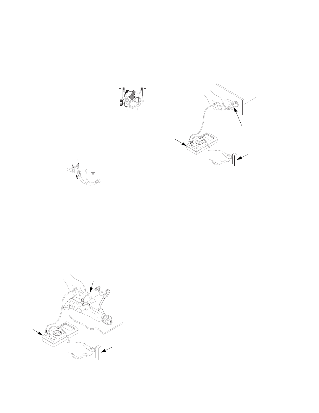
Check Electrical Grounding
1. Have a qualified electrician check the electrical
grounding continuity of the spray gun and air hose.
2. Turn the ES ON/OFF valve OFF.
ES
I O
ti1273a
3. Turn off the air and fluid supply to th e gun. The flui d
hose must not have any fluid in it.
4. Make sure the red-colored grounded air hose (R) is
connected and the hose ground wire is connected to
a true earth ground.
7. Using an ohmmeter (AA), measure the re sist an ce
between the cabinet ground lug (214) and a true
earth ground (CC). See F
IG. 15.. The resistance
must be less than 100 ohms.
Fig. 15. Check Cabinet Grounding
5. Using an ohmmeter (AA), measure the resistance
between the gun handle (BB) and a true earth
ground (CC). The resistance should not e xceed 100
ohms. See F
IG. 14..
6. If the resistance is greater than 100 ohms, check th e
tightness of the ground connections and be sure the
air hose ground wire is connected to a true earth
ground. If the resistance is still too high, replace the
air hose.
Fig. 14. Check Gun Grounding
18 309293N
Page 19

Operation
Operation
Operating Checklist
Check the following list daily, before starting to operate the system, to help ensure you of safe, efficient operation.
All operators are properly trained to safely
operate an electrostatic waterborne air spray
system as instructed in this manual.
All operators are trained in the Pressure
Relief Procedure on page 20.
The electrostatics are turned off and properly
grounded according to the.Fluid Voltage Dis-
charge and Grounding Procedure on page
20 before any person enters the safety enclosure, before cleaning, and before performing
any maintenance or repair.
The system is thoroughly grounded and the
operator and all persons entering the spray
area are properly grounded. See Grounding
on page 17.
Fluid Hose is in good condition with no cuts or
abrasions of the PTFE layer. Replace hose if
damaged.
Ventilation fans are operating properly.
Workpiece hangers are clean and grounded.
All debris, including flammable fluids and rags,
is removed from the spray area.
Only fluids with a flash point above 140F
(60C) and a maximum organic solvent concentration of 20%, by weight, may be in the
spray area.
All conductive objects in the spray area are
electrically grounded and the floor of the spra y
area is electrically conductive and grounded.
309293N 19
Page 20
Operation
ti1289a
Fluid Voltage Discharge and Grounding Procedure
WARNING
Electric Shock Hazard
The fluid supply is charged with high voltage until the voltage is discharged. Contact
with the charged components of the isola-
tion system or spray gun electrode will
cause an electric shock. To avoid an electric shock,
follow the Fluid Voltage Discharge and Grounding
Procedure:
• whenever you are instructed to discharge the
voltage
• before cleaning, flushing, or servicing the syst em
equipment
Pressure Relief Procedure
WARNING
Pressurized Equipment Hazard
The system pressure must be manually
relieved to prevent the system from starting
or spraying accidentally. To reduce the risk
of an injury from electric shock, accidental spray from
the gun, splashing fluid, or moving parts, follow the
Pressure Relief Procedure whenever you:
• are instructed to relieve the pressu re
• stop spraying
• check or service any of the system equipment
• or install or clean the fluid nozzle.
• before approaching the front of the gun
• or before opening the safety enclosure for the
isolated fluid supply.
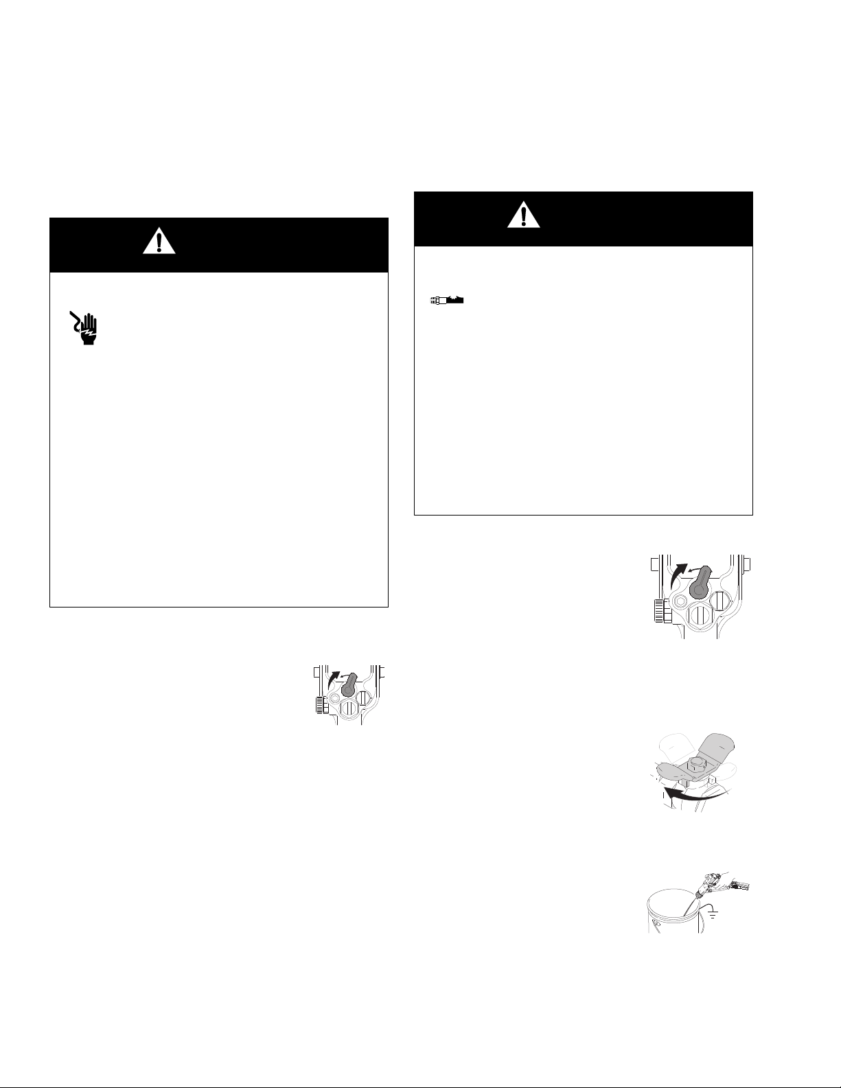
1. Turn the ES ON/OFF valve OFF and wait 30 seconds.
ES
I O
ti1273a
2. Remove the door T-handle locking screw. This will
shut off the air to the gun and trigger the grounding
cylinder to discharge any remaining electrical
charge.
3. Use the grounding rod to touch the pump and su pply pail. If you see any arcs, see Electrical Trouble-
shooting on page 39.
1. Turn the ES ON/OFF valve OFF.
ES
I O
ti1273a
2. Follow the Fluid Voltage Discharge and Ground-
ing Procedure at left.
3. Turn off the main air supply valve (B).
4. Trigger the gun into a grounded metal was te co ntainer to relieve the air and fluid pressure.
ti1276a
5. Relieve fluid pressure in the fluid supply unit as
instructed in your fluid supply unit manual.
20 309293N
Page 21
Fill the Fluid Supply
Operation
1. Discharge the system voltage (page 20).
2. Relieve the pressure (page 20).
ti1276a
3. Open the isolated enclosure door.
4. Remove the pail cover from the pail, holding a rag
over the suction tube strainer to prevent any fluid
from dripping into the isolated enclosure. Place the
cover and suction tube outside the enclosure.
5. Remove the supply pail from the enclosure.
CAUTION
Be sure to wipe up all fluid spills in the isolated enclosure. Fluid can create a conductive path and caus e
the system to short out.
6. Clean up any fluid spills in the enclosure, using a
soft cloth and a non-flammable, compatible solvent.
7. Fill the supply pail with fluid and return it to the
enclosure. Clean up any spills.
8. Reinstall the pail cover, holding a rag over the suction tube strainer to prevent fluid spills while you
place the pump suction tube in the pail.
WARNING
Fire and Explosion Hazard
To reduce the risk of fire and explosion, only
use this equipment with fluids that meet at
least one of the following conditions for
non-flammability:.
• The fluid has a flash point above 140F (60C)
and a maximum organic solvent concentration of
20%, by weight, per ASTM Standard D93.
• The fluid does not sustain burning when tested
per ASTM Standard D4206 Sustained Burn Test.
WARNING
Electric Shock Hazard
Contact with the charged components of
the spray gun will cause an electric shock.
Do not touch the gun nozzle or electrode or
come within 4 in. (102 mm) of the front of the gun
during operation or until performing the Fluid Voltage
Discharge and Grounding Procedure on page 20.
Follow the Fluid Voltage Discharge and Grounding
Procedure on page 20 when you stop spraying and
whenever you are instructed to discharge the volta ge.
9. Close the isolated enclosure door and fasten
securely with the T-handle locking screw.
WARNING
Adjust the Spray Pattern
Follow the steps below to establish the correct fluid flow
and air flow.
309293N 21
Component Rupture Hazard
To reduce the risk of component rupture,
which can cause serious injury, do not
exceed the maximum working pressure of
the lowest rated system component. This equip ment
has a 100 psi (0.7 MPa, 7 bar) maximum working air
and fluid pressure.
Page 22

Operation
Vertical Pattern
Horizontal Pattern
ti1269a
100
%
KV
μα
0
HI
LO
ES
I O
ES
ti1272a
WARNING
Pressurized Equipment Hazard
To reduce the risk of an injury, follow the
Pressure Relief Procedure on page 20
whenever you are instructed to relieve the
pressure.
4. Fully open the fan air adjustment valve.
1. Make sure the ES ON/OFF valve is OFF.
ES
I O
ti1273a
2. Turn on the main air supply valve (B).
3. Position the air cap by loosening the air cap retaining ring, and rotating the air cap for a vertical or horizontal spray pattern. Tighten the retaining ring until
the air cap is held firmly in place; you should not be
able to rotate the air cap horns by hand.
5. Fully open the fluid adjustment valve .
0
KV
μα
HI
LO
ES
ES
I O
6. Fully open the atomizing air restrictor valve .
7. Make sure the ES ON/OFF valve is OFF.
100
%
ti1267a
22 309293N
ES
I O
ti1273a
Page 23

Operation
TI1760A
8-12 in. (200-300 mm)
TI1281A
ti1282a
8. Adjust the pump air regulator to start the f luid supply
unit. Adjust the fluid flow with the air pressure regulator until the stream from the gun travels 8-12 in.
(200-300 mm) before falling off. Typically, if fluid
pressure is below 5 psi (.04 MPa, 0.4 bar) or above
20 psi (0.14 MPa, 1.4 bar), a change of nozzle size
is recommended. Refer to instruction manual
309419 to set the fluid pressure for various fluid
flows, according to the size of the fluid no zzle be ing
used.
9. Set the gun air regulator to deliver a minimum 40 psi
(0.28 MPa, 2.8 bar) at the gun when trig gered, for
maximum transfer efficiency. See Table 3 .
10. Spray a test pattern. Check the atomization. If overatomization occurs at minimum pressure, ad just the
air atomizing restrictor valve. If atomization is inadequate, increase the air pressure.
11. Adjust the fan air adjustment valve: clockwise for a
rounder pattern, counterclockwise for a wider pattern.
Table 3: Air Regulator Settings
Air Hose Length
ft (m)
(5/16 in. [8 mm] diameter)
15 (4.6) 50 (0.35, 3.5)
25 (7.6) 60 (0.42, 4.2)
50 (15.3) 75 (0.52, 5.2)
NOTE:
• For the most efficiency, always use the lowest air
pressure possible.
• When increasing to a wide, flat pattern, it may be
necessary to increase the supply of fluid to the gun
to maintain the same amount of coverage ove r a
large area.
Air Regulator Setting
psi (MPa, bar)
(with gun triggered)
WARNING
Electric Shock Hazard
When the ES ON/OFF switch is turned ON,
the fluid supply is charged with high voltage
until the voltage is discharged. Contact with
the charged components of the spray gun
will cause an electric shock. Do not touch the gun
nozzle or electrode or come within 4 in. (102 mm) of
the front of the gun during operation.
12. Turn the ES ON/OFF switch ON (I).
ES
I O
ti1283a
ti1284a
309293N 23
Page 24

Operation
ti1253a
100
%
KV
μα
0
HI
LO
ES
I OI O
ES
ti1285a
13. Check that the ES indicator or display is lit , or check
that the kV indicator on the isolated enclosure reads
45-55 kV. If not, see Electrical Troubleshooting on
page 39 for possible problems.
ES
I O
ti1266a
14. Check the kV meter on the isolated enclosure;
45-55 kV is normal.
15. Spray a test piece. Examine the edges f or coverage.
If wrap is poor, see Spray Pattern Troubleshoot-
ing on page 37.
16. When you finish spraying, perform the Shutdown
procedure on page 25.
24 309293N
Page 25

Operation
ti1288a
100
%
KV
μα
0
ti1529a
53
12
ON
OFF
Shutdown
1. Discharge the system voltage (page 20).
2. Flush the spray gun. See page 26.
WARNING
Pressurized Equipment Hazard
To reduce the risk of an injury, follow the
Pressure Relief Procedure on whenever
you are instructed to relieve the pressure.
3. Relieve the pressure (page 20).
ti1276a
2. Remove the LO VOLTAGE adjustment plug (53). Set
the desired voltage, using a small screwdriver to
slide switches 1 and 2 ON or OFF, according to
Table 4 . Also see F
IG. 16..
Fig. 16. Low Voltage Adjustment Switches
Table 4: Low Voltage Adjustment
12kV
ON ON 50
Factory Setting >ON OFF 40
OFF ON 35
OFF OFF 30
ti1276a
4. Hang the gun from its hook or place it in the accessory holster, with the nozzle pointing down. Be sure
to keep the gun from grounding out.
Low Voltage Adjustment (Smart Guns Only)
The ES HI/LO switch enables you to switch between full
voltage and a lower voltage output. The lower voltage is
factory set, but can be adjusted.
1. Set the ES HI/LO switch to LO.
309293N 25
Page 26

Maintenance
ti1288a
Maintenance
Flush the Spray Gun
Flush the gun before changing colors, at the end of the
day, before storing, and before repairing the gun.
WARNING
Fire, Explosion, and Electric Shock Hazard
To reduce the risk of fire, explosion, or electric shock, turn the ES ON/OFF valve OFF
before flushing the gun.
Follow the Fluid Voltage Discharge and
Grounding Procedure on page 20 before
flushing.
Only flush, purge, or clean the gun with fluids that
meet at least one of the following conditions for
non-flammability:
1. Turn the ES ON/OFF valve OFF and wait 30 seconds for the voltage to bleed off.
ES
I O
ti1273a
2. Discharge the system voltage (page 20).
3. Relieve the pressure (page 20).
ti1276a
4. Change the fluid source to solvent.
5. Point the gun into a grounded metal pail. Flush until
clean solvent flows from the gun.
• The fluid has a flash point above 140F (60C)
and a maximum organic solvent concentration of
20%, by weight, per ASTM Standard D93.
• The fluid does not sustain burning when tested
per ASTM Standard D4206 Sustained Burn Test.
WARNING
Pressurized Equipment Hazard
To reduce the risk of an injury, follow the
Pressure Relief Procedure on page 20
whenever you are instructed to relieve the
pressure.
ti1276a
6. Relieve the pressure.
ti1276a
7. Open the isolated enclosure door. Leave the flushing fluid in the system until you are ready to spray
again.
8. Hang the gun from its hook, with the nozzle po inting
down. Be sure to keep the gun from grounding out.
9. Before using the system electrostatically again,
make sure no flammable vapors are present.
26 309293N
Page 27

Daily Care and Cleaning
ti1295a
Maintenance
CAUTION
• Clean the outside of the gun daily with a soft cloth
dampened with a non-flammable solven t, as
defined on page 26.
• Check for fluid leaks. Tighten all fittings.
• Clean the air cap and fluid nozzle daily, minimum.
See page 29. Some applications require more frequent cleaning.
• Fluid in the air passages could cause the gun to
malfunction and could draw current and reduce the
electrostatic effect. Fluid in the power supply cavity
can reduce the alternator life. Do not use any
cleaning method which could allow fluid into the
gun air passages.
• Hang the gun with its nozzle pointing down when it
is not being used.
• Clean the workpiece hangers with non-sparking
tools.
• Clean the fluid and air line filters daily.
Do not immerse the gun in fluid.
ti1294a
• Check the movement of the trigger and valves.
Lubricate if necessary.
Do not point the gun up while cleaning it. Do not wipe the gun with a cloth that is heavily satu-
rated; wring out the excess fluid.
ti1293a
309293N 27
Page 28

Maintenance
240
• Inspect the cabinet and clean up any spilled paint.
Conductive paint residue allowed to contact
grounded parts may short out the electrostatics.
• Keep the inside of the cabinet clean, for proper
operation.
• Visually inspect the ground strip (240) for damage.
Replace if needed. Measure the resistance weekly.
See page 33.
CAUTION
28 309293N
Page 29

Maintenance
ti1297a
9
27
29
7
Clean the Air Cap and Fluid Nozzle
Equipment Needed
• soft bristle brush
• non-flammable solvent
Procedure
1. Turn the ES ON/OFF valve OFF. Wait 30 seconds.
ES
I O
ti1273a
2. Discharge the system voltage (page 20).
3. Relieve the pressure (page 20).
NOTE: If it appears that there is paint inside the fluid
nozzle (7) air passages, remove the gun from the line for
servicing.
7. Carefully install the air cap (9). Be sure to insert the
electrode (29) through the ce nter hole of the air cap.
Rotate the air cap to the desired position.
8. Tighten the retaining ring (27) until the air cap is
held firmly in place; you should not be able to rotate
the air cap horns by hand.
9. Test gun resistance, page 30.
ti1276a
4. Remove the retaining ring (27) and air cap (9 ). See
IG. 17..
F
CAUTION
Do not use metal tools to clean the
air cap or fluid nozzle holes as this
could scratch them, and make sure
the electrode is not damaged.
Scratches in the air cap or nozzle or
a damaged electrode can distort the
spray pattern.
5. Clean the air cap (9) with the soft bristle brush and
non-flammable solvent or submerge the air cap in
solvent and wipe it clean.
6. With the gun pointing down, clean the fluid nozzle
(7) and the front of the gun with a soft brush dampened with non-flammable solvent.
Fig. 17. Clean Air Cap and Fluid Nozzle
Grease Door Latch Threads
Inspect the door T-handle locking screw regularly, to
ensure the threads are well greased. Apply silicone-free
grease to the threads when necessary.
309293N 29
Page 30

Electrical Tests
TI1688B
AA
35
29
Electrical Tests
Electrical components inside the gun af fect performance
and safety. The following procedures test the condition
of the power supply (18) and electrode (29), and electrical continuity between components.
Use megohmmeter Part No. 241079 (AA) and an
applied voltage of 500 V. Connect the leads as shown.
WARNING
Fire, Explosion, and Electric Shock Hazard
Megohmmeter Part No. 241079 (AA-see
F
IG. 18.) is not approved for use in a haz-
ardous area. To reduce the risk of sparking,
do not use the megohmmeter to check electrical grounding unless:
•The gun has been removed from the hazardous area;
•Or all spraying devices in the hazardous
area are turned off, ventilation fans in the
hazardous area are operating, and there
are no flammable vapors in the area
(such as open solvent containers or
fumes from spraying).
Failure to follow this warning could cause
fire, explosion, and electric shock and r esult
in serious injury and property damage.
Test Gun Resistance
1. Prepare the gun for service as instructed on page
41.
2. Measure resistance between the electrode needle
tip (29) and the air swivel (35); it should be 117-137
megohms. If outside this range, go to the next test. If
you still have problems, refer to Voltage Loss Trou-
bleshooting on page 34 for other possible causes
of poor performance, or contact your Graco distr ibutor.
Fig. 18. Test Gun Resistance
30 309293N
Page 31

Test Power Supply Resistance
EE
18b
1. Prepare the gun for service as instructed on page
41.
2. Remove the power supply (18), page 46.
3. Remove the turbine alternator (19) f rom the power
supply, page 47.
4. Measure resistance from the power supply's ground
strips (EE) to the spring (18b). See F
5. The resistance should be 95-105 megohms. If outside this range, replace the power supply. If in
range, proceed to the next test.
6. Be sure the spring (18b) is in place before reinstalling the power supply.
IG. 19..
Electrical Tests
ti1599a
Fig. 19. Test Power Supply Resistance
309293N 31
Page 32

Electrical Tests
ti1499a
B
29
C
ti1548a
F29E
7a
Test Electrode Resistance
1. Prepare the gun for service as instructed on page
41.
2. Insert a conductive rod (B) into the gun barrel
(removed for the power supply test) and aga inst the
metal contact (C) in the front of the barrel.
3. Measure the resistance between the conductive rod
(B) and the electrode (29). The resist ance should be
20-30 megohms. See F
4. If in range, refer to Electrical Troubleshooting on
page 39 for other possible causes of poor performance, or contact your Graco distributor.
IG. 20..
5. Remove the electrode (29), page 43. Measure the
resistance between the contact (E) and the electrode wire (F). The resistance should be 20-30 megohms. If out of range, replace the electrode. See
IG. 21..
F
6. Make sure the metal contact (C) in the barrel, the
nozzle contact ring (7a, F
IG. 22.), and the electrode
contact (E) are clean and undamaged.
Fig. 21. Electrode
ti1513a
Fig. 22. Nozzle Conductive O-Ring
Fig. 20. Test Electrode Resistance
32 309293N
Page 33

Test Ground Strip Resistance
206
214
209
214
See FIG. 23.. Using an ohmmeter, measure the resistance between the latch housing (206) and the ground
lug (214). The ground strip is groun de d t hroug h t he ca rt
back to the ground lug. Resistance must be less than
100 ohms. If greater than 100 ohms, re place the groun d
strip (240).
Electrical Tests
Fig. 24. Test Cylinder Resistance
Fig. 23. Test Ground Strip Resistance
Test Cylinder Resistance
See FIG. 24.. Remove the enclosure door. Usin g an
ohmmeter, measure the resistance from the pump (209)
to the ground lug (214). Resistance must be less than
100 ohms. If greater than 100 ohms, re place the
grounding cylinder.
309293N 33
Page 34

Troubleshooting
Troubleshooting
Spray Gun
• Fluid leakage
WARNING
Electric Shock Hazard
Installing and servicing this equipment
requires access to parts which may cause
an electric shock or other serious injury if
the work is not performed properly. Do not install or
repair this equipment unless you are trained and
qualified.
Follow the Fluid Voltage Discharge and Grounding
Procedure on page 20 before checking or servicing
the system and whenever you are instructed to discharge the voltage.
WARNING
Pressurized Equipment Hazard
To reduce the risk of an injury, follow the
Pressure Relief Procedure on page 20
before checking or servicing any part of the
system and whenever you are instructed to
relieve the pressure.
• Dielectric breakdown at the fluid hose connect ion or
fluid packings
• Not enough air pressure for the turbine
• Faulty power supply
• Excessive overspray on gun surfaces
• Fluid in the air passages
Waterborne Fluid Hose
• Dielectric failure of hose (pin-hole leak through
PTFE layer)
• Air gap in the fluid column between the gun and isolated fluid supply, causing a low voltage reading on
the isolation system voltage meter.
Voltage Isolation System
• Fluid leakage
• Dirty interior
Voltage Loss Troubleshooting
Normal spraying voltage for a system using the waterborne gun is 45-55 kV. The system voltage is lower due
to spraying current demands and voltage isolation system losses.
A loss of spraying voltage can be caused by a problem
with the spray gun, fluid hose, or voltage isolation system, since all of the system components are electrically
connected through the conductive, water b or ne fluid .
Before troubleshooting or servicing the voltage isolation
system itself, you need to determine which comp o nent
in the system is most likely causing a problem. Possible
causes include the following:
34 309293N
Page 35

Troubleshooting
Visual Check
First, check the system for any visible faults or errors to
help isolate whether the spray gun, fluid hose or voltag e
isolation system has failed. A voltage probe and meter,
part no. 236003, is helpful for diagnosing voltage problems and is required for some of the troubleshooting
tests that follow.
1. Check that all of the air and fluid tubes and hoses
are properly connected.
2. Check that the voltage isolation system valves and
controls are properly set for operation.
3. Check that the interior of the isolated enclosure is
clean.
4. Check that the spray gun and voltage isolation system have sufficient air pressure.
5. Check that the gun ES ON/OFF valve is in the ON
position and that the gun ES indicator light is on. If
the ES indicator light is not on, remove the spray
gun for service and complete the electrical test s on
pages 30- 32.
10. Inspect the entire system for any visible fluid leakage and repair any fluid leaks that are found. Pay
special attention to the following areas:
• Packing area of the spray gun
• Fluid hose: check for leakage or any bulges in the
outer cover, which may indicate an internal leak
• Internal voltage isolation system components
Tests
If you still have no voltage, separate the spray gun and
hose from the voltage isolation system and check
whether the gun and hose alone will hold voltage with
the following test.
1. Flush the system with water and leave the lines
filled with water.
2. Discharge the system voltage (page 20).
3. Relieve the pressure (page 20).
4. Disconnect the fluid hose from the voltage isolation
system.
6. Check that the voltage isolation system's enclosure
door is closed and that any safety interlocks are
engaged and working properly.
7. Make sure the voltage isolation system is in the “isolate” mode, where it is isolating the fluid voltage
from ground.
8. To eliminate air gaps in the fluid column, spray
enough fluid to purge the air out between the voltage isolation system and the spray gun. An air gap
in the fluid hose can break the electrical continuity
between the spray gun and the isolated fluid supply
and cause a low voltage reading on a voltage meter
connected to the isolated fluid supply.
9. Check the spray gun cover and barrel for accumu lated overspray. Excessive overspray can create a
conductive path back to the grounded gun handle.
Install a new gun cover and clean the exterior of the
gun.
NOTE: Avoid allowing any water to leak out of the fluid
hose as that could cause a significant air gap in the flui d
column up to the gun electrode, which can break the
conductivity path and conceal a potential failure area.
5. Position the end of the hose as far as possible away
from any grounded surface. The end of the h ose
must be at least 1 ft. (0.3 m) from any ground. Make
sure that no one is within 3 ft. (0.9 m) of the end of
the hose.
6. Turn the ES ON/OFF valve to ON and trigger the
gun just enough to turn on the air to the gun but not
the fluid. Measure the voltage at the gun electrode
with a voltage probe and meter.
7. Discharge the system voltage by waiting 30 seconds and then touching the gun electrode with a
grounded rod.
8. If the meter reading is 45 to 55 kV, the gun and fl uid
hose are okay, and the problem is in the voltage isolation system.
If the reading is below 45 kV, the problem is in the
gun or fluid hose.
309293N 35
Page 36

Troubleshooting
9. Flush the fluid hose and gun with enough air to dry
out the fluid passages.
10. Turn the ES ON/OFF valve to ON and trigger the
gun. Measure the voltage at the gun electrode with
a voltage probe and meter.
11. If the meter reading is 45-55 kV, the gun power supply is okay, and there is probably a dielectric breakdown somewhere in the fluid hose or gun. Continue
with step 12.
If the reading is below 45 kV, do the electrical tests
on page 30 to check the gun and power supply
resistance. If those tests show the gun and power
supply are okay, continue with step 12.
12. A dielectric breakdown is most likely in one of the
following three areas. Repair or replace the component that is failing.
• Fluid hose
Check for leakage or any bulges in the outer cover,
which may indicate a pin-hole leak through the
PTFE layer. Disconnect the fluid hose from th e gun,
and look for signs of fluid contamination on the outside of the PTFE portion of the fluid tube.
13. Before reassembling the gun, clean and dry the gun
fluid inlet tube. Repack the inner spacer of the fluid
packing rod with dielectric grease and reassemble
the gun.
14. Reconnect the fluid hose.
15. Check the gun voltage with the voltage probe and
meter before filling the gun with fluid.
Inspect the end of the hose connected to the voltage isolation system. Look for cuts or nicks.
Make sure the hose is properly stripped (see step 2
on page 12). Restrip or replace the hose.
• Fluid packings
Remove the packing assembly from the gun as
instructed on page 44, and look for signs of fluid
leakage or any blackened areas, which would indicate arcing is occurring along the packing rod.
• Fluid hose connection joint to the spra y gun
A breakdown at the fluid hose connection joint
would be caused by fluid leaking past the o-ring
seals on the end of the hose. Remove the hose at
the gun connection and look for signs of fluid leakage along the PTFE tube.
36 309293N
Page 37

Spray Pattern Troubleshooting
NOTE: Check all possible remedies in the Troubleshooting Chart before disassembling the gun.
NOTE: Some spray pattern problems are caused by the improper balance between air and fluid.
Problem Cause Solution
Fluttering or spitting spray. No fluid. Refill supply.
Loose, dirty, damaged nozzle/seat. Clean or replace nozzle, page 42.
Air in fluid supply. Check fluid source. Refill.
Improper spray pattern. Damaged nozzle or air cap. Replace, page 42.
Fluid buildup on air cap or nozzle. Clean. See page 29.
Troubleshooting
Fan air pressure too high. Decrease.
Fluid too thin. Increase viscosity.
Fluid pressure too low. Increase.
Fan air pressure too low. Increase.
Fluid too thick. Reduce viscosity.
Too much fluid. Decrease flow.
Streaks. Did not apply 50% overlap. Overlap strokes 50%.
Dirty or damaged air cap. Clean or replace, page 42.
309293N 37
Page 38

Troubleshooting
Gun Operation Troubleshooting
Problem Cause Solution
Excessive spray fog. Atomizing air pressure too high. Close restrictor valve some, or
decrease air pressure as low as possible; minimum 40 psi (0.28 MPa, 2.8
bar) needed at gun for full voltage.
Fluid too thin. Increase viscosity.
“Orange Peel” finish. Atomizing air pressure too low. Open atomizing air valve more or
increase gun air inlet pressure; use
lowest air pressure necessary.
Poorly mixed or filtered fluid. Remix or refilter fluid.
Fluid too thick. Reduce viscosity.
Fluid leaks from the fluid packing
area
Air leaks from the front of the gun Air valve (21) is not seating properly. Clean and service air valve; see
Fluid leakage from the front of the
gun
Gun does not spray Low fluid supply. Add fluid if necessary.
Dirty air cap Misaligned air cap (9) and fluid noz-
Worn packings or rod. Replace packings or rod; see page
45.
page 50.
Worn or damaged packing rod (26). Replace; see page 45
Worn fluid seat. Replace fluid nozzle and/or electrode
needle; see pages 42 to 43.
Loose fluid nozzle (7). Tighten; see page 42.
Damaged nozzle o-ring (7b). Replac e; see page 42.
Damaged air cap (9). Replace; see page 42.
Dirty or clogged fluid nozzle (7). Clean; see page 42.
Damaged fluid nozzle (7). Replace; see page 42.
Damaged fluid adjustment valve (25). Replace; see page 50.
Clean fluid buildup off air cap and
zle (7).
fluid nozzle seat; see page 29.
38 309293N
Page 39

Electrical Troubleshooting
Problem Cause Solution
Voltage still present at gun after following the Fluid Voltage Discharge
and Grounding Procedure
Poor wrap. ES ON/OFF valve OFF (0).* Turn ON (I).
ES ON/OFF valve is not turned OFF. Turn OFF.
Did not wait long enough for voltage
to discharge.
Air pocket in fluid line leaves fluid
near gun isolated.
Voltage isolation system failed. Service voltage isolation system.
Grounding cylinder not operating. Check resistance of grounding cylin-
Gun air pressure too low. Check air pressure to gun; minimum
Atomizing air pressure too high. Decrease.
Fluid pressure too high. Decrease.
Incorrect distance from gun to part. Should be 8-12 in. (200-300 mm).
Poorly grounded parts. Resistance must be 1 megohm or
Faulty gun resistance. See Test Gun Resistance on page
Fluid leaks from the packing (26d)
and causes a short.
Faulty turbine alternator. Be sure the plug is in place on the
The KV HI-LO lever is on LO. Check the lever actuation; replace if
Spilled paint, dried paint, or other
contaminants inside WB100 enclosure, causing a short circuit.
Wait longer before touching electrode
with grounded rod. Check for bleed
resistor failure.
Determine cause and correct. Purge
air from fluid line.
der, page 33. Replace if needed.
40 psi (0.28 MPa, 2.8 bar) needed at
gun for full voltage.
less. Clean workpiece hangers.
30.
Clean the packing rod cavity.
Replace the packing rod. See page
45.
back of the turbine alternator housing. Remove and test the turbine
alternator. See page 48.
needed.
Clean interior of enclosure.
Troubleshooting
309293N 39
Page 40

Troubleshooting
Problem Cause Solution
ES indicator or voltage/current dis-
ES ON/OFF valve OFF (0).* Turn ON (I).
play is not lit.
No power. Replace power supply. See page 47.
Voltage/current display stays red
Gun too close to part. Should be 8-12 in. (200-300 mm).
(smart guns only).
Check fluid resistivity. See Operation on page 19.
Dirty gun. Clean. See page 27.
Operator gets mild shock. Operator not grounded or is near
See Grounding on page 17.
ungrounded object.
Gun not grounded. See Check Electrical Grounding on
page 18 and Test Gun Resistance
on page 30.
A weak static charge has built up on
the surface of an unshielded fluid
hose. This is a charge on the hose
Bundle and wrap the air and fluid
hoses together. See Connect the
Waterborne Fluid Hose, page 11.
surface, not a failure of the hose insulation.
Operator gets shock from workpiece. Workpiece not grounded. Resistance must be 1 megohm or
less. Clean workpiece hangers.
* ES indicator light is off when the gun is triggered.
40 309293N
Page 41

Repair
Repair
Prepare the Gun for Service
WARNING
Fire, Explosion, and Electric Shock Hazard
To reduce the risk of a fire, explosion, or
electric shock:
•Follow the Fluid Voltage Discharge and
Grounding Procedure on page 20 and
be sure the ES ON/OFF valve is OFF
before flushing, checking, or servicing
the system and whenever you are
instructed to discharge the voltage.
•Clean all parts with a non-flammable fluid
as defined on the front cover of this manual.
•Do not service this equipment unless you
are trained and qualified.
• Check all possible remedies in Troubleshooting
before disassembling the gun.
• Use a vise with padded jaws to prevent damage to
plastic parts.
• Lubricate the power supply o-ring (18a), some packing rod parts (26), and certain fluid fittings with
dielectric grease (40), as specified in the text.
• Lightly lubricate o-rings and seals with non-silicone
grease. Order Part No. 111265 Lubricant. Do not
over-lubricate.
• Only use genuine Graco parts. Do not mix or use
parts from other PRO Gun models.
• Air Seal Repair Kit 244781 is available. The kit must
be purchased separately. Kit parts are marked with
an asterisk, for example (6*).
• Fluid Seal Repair Kit 244911 is available. The kit
must be purchased separately. Kit parts are marked
with a double asterisk, for example (26a**).
•Do not touch the gun nozzle or come within
4 in. (102 mm) of the nozzle during gun
operation or until you perform the Fluid
Voltage Discharge and Grounding
Procedure on page 20.
WARNING
Pressurized Equipment Hazard
To reduce the risk of injury, follow the Pressure Relief Procedure on page 20 before
checking or servicing any part of the system
and whenever you are instructed to relieve the pressure.
NOTE:
1. Follow the Fluid Voltage Discharge and Grounding Procedure on page 20.
2. Flush the gun, page 26.
3. Blow the fluid lines dry with air.
4. Relieve the pressure, page 20.
5. Disconnect the gun air and fluid lines at the isolation
system.
6. Remove the gun from the worksite. Repa ir area
must be clean.
309293N 41
Page 42

Repair
27
9
7
7a
7b
27a*
37
Air Cap/Nozzle Replacement
WARNING
CAUTION
Hold the front end of the gun up and trigger the gun
while removing the nozzle to help drain the gun and
prevent any paint or solvent left in the gun from entering the air passages.
1. Prepare gun for service, page 41.
2. Remove the retaining ring (27) and air cap (9 ). See
IG. 25..
F
3. Point gun up and squeeze trigger while removing
the fluid nozzle (7) assembly with the multi-tool (37).
Fire, Explosion, and Electric Shock Hazard
The nozzle contact ring (7a) is a conductive
contact ring, not a sealing o-ring. To reduce
the risk of sparking or electric shock, do not
remove the nozzle contact ring (7a) except
to replace it and never operate the gun with out the contact ring in place. Do not repla ce
the contact ring with anything but a genuin e
Graco part.
NOTE: Use non-silicone grease, Part No. 111265, on
the small o-ring (7b). Do not over-lubricate. Do not lubricate the contact ring (7a).
4. Lightly lubricate the o-ring (7b). Install it and th e
contact ring (7a) on the nozzle (7).
NOTE: Make sure the electrode needle (29) is fingertight (page 43).
5. Trigger gun while installing the fluid nozzle (7) with
the multi-tool (37). Tighten until the fluid no zzle
seats in the gun barrel (1/8 to 1/4 turn past
hand-tight).
6. Install the air cap (9) and retaining ring (27). Make
sure the u-cup (27a*) is in place with the lips facing
forward.
7. Test gun resistance, page 30.
ti1501a
Fig. 25. Air Cap/Nozzle Replacement
42 309293N
Page 43

Electrode Replacement
37
1. Prepare the gun for service, page 41.
2. Remove the air cap and nozzle, page 42.
3. Unscrew the electrode (29) with the multi-tool (37).
Hold the packing rod end (26h) to prevent it from
turning, F
IG. 26..
CAUTION
To avoid damaging the plastic threads, be very careful when installing the electrode.
®
4. Apply low-strength (purple) Loctite
thread sealant to the electrode and packing rod
threads. Install the electrode finger-tight. Do not
overtighten.
or equivalent
Repair
5. Install the fluid nozzle and air cap, page 42.
6. Test gun resistance, page 30.
TI1682a
Fig. 26. Electrode Replacement
309293N 43
Page 44

Repair
TI1683A
37
30
8
Fluid Packing Removal
1. Prepare the gun for service, page 41.
2. Remove the air cap and fluid nozzle, page 42.
3. Remove the electrode, page 43.
4. Loosen the trigger screws (8) and trigger (30). See
F
IG. 27..
5. Remove the packing rod (26), using the multi-tool
(37).
CAUTION
Clean all parts in non-conductive solvent compatible
with the fluid being used, such as xylol or mineral
spirits. Use of conductive solvents can cause the gun
to malfunction.
6. Check all parts for wear or damage and replace if
necessary.
Fig. 27. Fluid Packing Removal
44 309293N
Page 45

Repair
**26a
**26b
**26d
**26c
26e
26f
**26g
26h
E
4
Packing Rod Repair
You may replace the packing rod as individual parts or
as an assembly. The assembly is pre-adjusted at the
factory.
NOTE: Before installing the fluid packing rod into the
gun barrel, make sure the internal surfaces of t he ba rrel
are clean. Remove any residue with a soft brush or
cloth. Check the inside of the barrel for marks from hig h
voltage arcing. If marks are present, replace the barrel.
To assemble the individual parts:
1. Place the packing nut (26e) and seal (26b**) on the
fluid rod (26h). Flats on the packing nut must face
the back of the fluid rod. The seal o-ring must face
away from the packing nut. See F
2. Fill the inner cavity of the spacer (26g**) with dielectric grease (40). Place the spacer on the fluid rod
(26h) in the direction shown. Generously apply
dielectric grease to the outside of the spacer.
IG. 28..
4. Lightly tighten the packing nut (26e). The packing
nut is properly tightened when there is 3 lb (13.3 N)
of drag force when sliding the packing housing (26f)
assembly along the rod. Tighten or loosen the packing nut as needed.
5. Install the o-ring (26a**) on the outside of housing
(26f). Lubricate the o-ring with non-silicone grease,
Part No. 111265. Do not over-lubricate.
6. Install the spring (4) against the nut (E) as shown.
7. Install the packing rod assembly (26) into the gun
barrel. Using the multi-tool (37), tighten the assembly until just snug.
8. Install the trigger (30) and screws (8).
9. Install the electrode, page 43.
10. Install the nozzle and air cap, page 42.
11. Test gun resistance, page 30.
3. Place the packing spreader (26c**), rod packing
(26d**), and housing (26f) on the packing rod (26h).
Fig. 28. Packing Rod
TI1489A
309293N 45
Page 46

Repair
TI1691A
11
35
104
16
17
17
TI1692A
16
*10
11
18
55
101
104
105
35
Barrel Removal
1. Prepare the gun for service, page 41.
2. Remove the air inlet fitting (35) and take th e bracket
(104) off the gun handle (17).
3. Loosen the three screws (11).
CAUTION
To avoid damaging the power supply (18), pull the
gun barrel straight away from the gun handle. If necessary, gently move the gun barrel from side to side
to free it from the gun handle.
4. Hold the gun handle (17) with one hand and pull the
barrel (16) straight off the handle. See F
IG. 29..
7. Test gun resistance, page 30.
TI1690A
Fig. 29. Barrel Removal
Barrel Installation
1. Be sure the gasket (10*) and grounding spring (55)
are in place. Make sure the gasket air holes are
aligned properly. Replace if damaged. See F
2. Place the barrel (16) over the power su pply (18) and
onto the gun handle (17).
3. Tighten the three screws (11) oppositely and evenly
(about a half turn past snug).
CAUTION
Do not over-tighten the screws (11).
4. Position the bracket (104) on the gun handle (17)
and secure with the air inlet fitting (35).
5. Apply dielectric grease (40) to the exposed inner
tube of the fluid hose (101).
6. Check that the nut (105) is tight on the ferrule housing (103).
IG. 30..
Fig. 30. Barrel Installation
46 309293N
Page 47

Repair
ti1505c
19
*18a 18b
10*
19a*
59
GG
18
19e
17
Power Supply Removal and Replacement
NOTE:
• Inspect the gun handle power supply cavity for dirt
or moisture. Clean with a clean, dry rag.
• Do not expose gasket (10) to solvents.
1. Prepare gun for service, page 41.
2. Remove the barrel (16), page 46.
CAUTION
Be careful when handling the power supply (18) to
avoid damaging it.
3. Grasp the power supply (18) with your hand. With a
gentle side to side motion, free the power supply/alternator assembly from the gun handle (17),
then carefully pull it straight out. On Smart Models
only, disconnect the flexible circuit (59) from the
socket at the top of the handle (17). See F
IG. 31..
9. Lubricate the power supply o-ring (18a*) wit h diele ctric grease (40).
10. Insert the power supply/alternator assembly in the
gun handle (17). Make sure the ground strips make
contact with the handle. On Smart Models only, connect the flexible circuit (59) to the socket at the top
of the handle. Push the 6-pin connector into the
socket to ensure it is properly connected.
11. Install the barrel (16), page 46.
12. Test gun resistance, page 30.
4. Disconnect the 3-wire connector (GG) from the
power supply. Slide the alternator up and off the
power supply. Inspect the power supply and alternator for damage. On Smart Models only, disconnect
the 6-pin flexible circuit (59) from the power supply.
5. Check the power supply resistance, page 31.
Replace if necessary.
NOTE: Before installing the power supply, make sure
the o-rings (18a*, 19a*), spring (18 b), and pads (19e)
are in place.
6. On Smart Models only, connect the 6-pin flexible circuit (59) to the power supply.
7. Connect the 3-wire connector (GG). Slide the alternator (19) down onto the power supply (18).
8. Lubricate the alternator o-ring (19a*) with non-silicone grease, Part No. 111265. Do not over-lubricate.
Fig. 31. Power Supply
309293N 47
Page 48

Repair
Turbine Alternator Removal and Replacement
NOTE: Replace turbine alternator bearings after 2000
hours of operation. Order Part No. 223688 Bearing Kit.
1. Prepare gun for service, page 41.
2. Remove the power supply/alternator assembly,
page 47.
3. Disconnect the alternator from the po wer supply,
page 47.
4. Measure resistance between the two outer terminals of the 3-wire connector (GG); it should be
2.5-3.5 ohms. If outside this range, replace the alternator coil.
5. Follow the bearing replacement procedure in the
bearing kit manual 308034.
6. Install the alternator on the power supply, page 47.
7. Install the power supply/alternator assembly, page
47.
48 309293N
Page 49

Repair
TI1487A
20a
20b*
20c
20d
Fan Air Adjustment Valve Repair
1. Prepare the gun for service, page 41.
2. Place a wrench on the flats of the valve assembly
(20) and unscrew it from the handle (17).
NOTE: You may replace the valve as an assembly (go to
step 9) or as individual parts (steps 3-9).
3. Remove the retaining ring (20a). See F
4. Turn the valve stem (20d) counterclockwise until it
comes free from the valve housing (20c).
5. Remove the o-ring (20b).
IG. 32..
6. Clean all parts and inspect for wear or damage.
NOTE: Use non-silicone grease, Part No. 111265. Do
not over-lubricate.
7. When reassembling the fan air valve (20), lightly
lubricate the valve threads and screw the stem (20d)
fully into the housing (20c) until bottomed. Install the
o-ring (20b*), lubricate, and unscrew the valve stem
until the o-ring enters the housing.
8. Reassemble the retaining ring (20a). Unscrew the
valve stem from the housing until it is stopped by the
retaining ring.
9. Screw the valve assembly (20) into the gun handle,
using a wrench on the flats of the housing. Torque to
15-25 in-lb (1.7-2.8 N•m).
Fig. 32. Fan Air Adjustment Valve
309293N 49
Page 50

Repair
TI1684A
25
TI1685A
25
15
21
*6
17
21a*
Fluid Adjustment Valve Repair
1. Prepare the gun for service, page 41.
2. Remove the fluid adjustment valve (25). It can only
be replaced as a complete assembly. See F
3. Screw the valve (25) into the gun handle. Torque to
15-25 in-lb (1.7-2.8 N•m).
IG. 33..
4. Remove the air valve (21) with a pliers. Inspect the
seal (21a*) and replace if damaged. Be sure the
seal is pressed securely onto the valve so the outer
cone is flats.
CAUTION
When removing the air valve (21) be careful not to
damage the seat area.
5. Inspect the u-cup (6*). Do not remove the u-cup
unless damaged. If removed, install the new one
with its lips facing into the gun handle (17).
6. Install the air valve (21) and spring (15 ) into the gun
handle (17).
7. Install the fluid adjustment valve (25). Torque to
15-25 in-lb (1.7-2.8 N•m).
8. Install the barrel, page 46.
Fig. 33. Fluid Adjustment Valve
Air Valve Repair
1. Prepare the gun for service, page 41.
2. Remove the barrel, page 46.
3. Remove the fluid adjustment valve (25) from the
handle (17). Remove the spring (15). See F
IG. 34..
CAUTION
Clean all parts in non-conductive solvent compatible
with the fluid being used, such as xylol or mineral
spirits. Use of conductive solvents can cause the gun
to malfunction.
Fig. 34. Air Valve
50 309293N
Page 51

Atomizing Air Restrictor Valve
TI1686A
23b
23a
23d
47
23c*
TI1488A
22a*
22b*
22c
22d
22e
22f
22g
48
Removal and Replacement
1. Prepare the gun for service, page 41.
2. Remove the atomizing air restrictor valve (23).
Inspect the o-ring (23c*). Replace if necessary. Se e
F
IG. 35..
Repair
CAUTION
Do not over-lubricate parts. Excessive lubricant on
the o-rings can be pushed into the gun air passage
and blemish the finish on the workpiece.
3. Install a new atomizing air restrictor valve (23), or
disassemble and replace parts individually. The
valve protrusion must be oriented to clear the air
valve (21) shaft.
NOTE: If the atomizing air restricto r valve is not desired,
install the supplied plug (47).
4. Torque the valve housing (23a) to 15-20 in-lb
(1.7-2.3 N•m).
4. Clean and inspect parts for damage. Replace if necessary.
NOTE: The protrusion on the retainer plate (22d) must
point upward.
5. Reinstall the valve. Torque the screw (48) to 15-25
in-lb (1.7-2.8 N•m).
Fig. 36. ES ON/OFF Valve
Fig. 35. Atomizing Air Restrictor Valve
ES ON/OFF Valve Repair
1. Prepare the gun for service, page 41.
2. Loosen the screw (48). Remove the valve.
3. Lubricate the o-rings (22a* and 22b*) with non-silicone grease, Part No. 111265. Do not over-lubricate.
309293N 51
Page 52

Parts
27
9
7
26
16
11
18
19
*10
17
28
20
22
25
15
21
23b
35***
24
38
8
*6
ti1266a
I O
ES
7a
7b
11
*18a
18b
23a
23c*
23d
*24a
27a*
29
30
37
36
39
47
4
See page 53 for detail views of the alternator (19), fan adjustment valve
(20), ES ON/OFF valve (22), and packing rod (26).
25 (Ref)
19a*
19e
55
101
102
103
104
105
107
106
108
21a*
Parts
Part No. 244581 60 kV Electrostatic Gun, Series B (items 4-55)
Part No. 245301 60 kV Electrostatic Gun with Shielded waterborne fluid hose, Series A (i tems 4-55, 101-108)
TI1679A
52 309293N
Page 53

Parts
ti1601a
Ref. No. 26: Packing Rod
TI1488A
TI1487A
22a*
22b*
22c
22d
22e
22f
22g
20a
20b*
20c
20d
26a**
26b**
26d**
26c**
26e
26f
26g**
26h
19a*
19b
19b
19c
Ref. No. 22: ES ON/OFF Valve
Ref. No. 20: Fan Adjustment ValveRef. No. 19: Alternator
48
19d
19e
TI1481a
309293N 53
Page 54

Parts
Part No. 244581 60 kV Electrostatic Gun, Series B (items 4-55)
Part No. 245301 60 kV Electrostatic Gun with waterborne fluid hose, Series A (items 4-55, 101-108)
Ref.
Part No. Description Qty
No.
Ref.
Part No. Description Qty
No.
4 185111 SPRING, compression 1
6* 188749 PACKING, u-cup, air valve;
uhmwpe
7 197266 NOZZLE; 1.5 mm orifice; includes
7a and 7b
7a 111261 . O-RING, conductive 1
7b 111507 . O-RING; fluoroelastomer 1
8 197369 SCREW, trigger 2
9 24A276 AIR CAP 1
10* 197517 GASKET, barrel 1
11 197518 SCREW; socket-hd; 10-24 x 3/4
in. (19 mm)
15 185116 SPRING, compression 1
16 244394 BARREL, gun 1
17 245292 HANDLE, gun; includes item 28 1
18 244542 POWER SUPPLY, 60 kV; includes
18a-18d
18a* 103337 . O-RING; fluoroelastomer 1
18b 197624 . SPRING, compression 1
19 244555 TURBINE, alternator; includes
19a-19e
20c 197566 . HOUSING, fan valve 1
20d 197567 . STEM, fan valve 1
21 244557 VALVE, air 1
1
21a* 276733 SEAL, fluoroelastomer 1
1
22 244558 VALVE, electrostatics, ON/OFF;
includes 22a-22g
22a* 111516 . O-RING; CV75 1
22b* 113137 . O-RING; fluoroelastomer 1
22c 198403 . SHAFT, valve 1
22d 198404 . PLATE, retaining 1
22e 198453 . WASHER 1
3
22f 198464 . PIN 1
22g 276753 . KNOB 1
23 244559 VALVE, air, atomizing; includes
23a-23d
23a 197594 . HOUSING, valve 1
1
23b 197591 . SHAFT 1
23c* 168518 . O-RING; fluoroelastomer 2
23d 101021 . RING, retaining 1
24 249323 VALVE, exhaust; includes 24a 1
1
24a* 112085 . O-RING; fluorocarbon 1
1
1
19a* 110073 . O-RING; fluoroelastomer 1
19b 223688 . BEARING KIT; includes front
and rear bearings and fan
19c 244577 . COIL 1
19d 111745 . RING, retaining 1
19e 198821 . PAD, pressure 2
20 244556 VALVE, adjustment, fan; includes
20a-20d
20a 101021 . RING, retaining 1
20b* 106560 . O-RING; fluorocarbon 1
54 309293N
25 244593 VALVE, adjustment, fluid 1
26 244521 ROD, packing; includes 26a-26h 1
1
26a** 111316 . O-RING; fluoroelastomer 1
26b** 116905 . SEAL 1
26c** 178409 . SPREADER, packing; uhmwpe 1
26d** 178763 . PACKING, rod; acetal 1
1
26e 197641 . NUT, packing 1
26f 185495 . HOUSING, packing 1
26g** 186069 . SPACER, packing; acetal 1
26h 244696 . ROD, packing 1
Page 55

Parts
Ref.
Part No. Description Qty
No.
27 245790 RING, retaining; includes 27a 1
27a* 198307 . PACKING, u-cup 1
28 276695 HOOK 1
29 276867 NEEDLE, electrode; black 1
30 276698 TRIGGER 1
35*** 245496 SWIVEL, air; 1/4 npsm(m);
left-hand threads
36 107460 WRENCH, ball end; 4 mm 1
37 276741 MULTI-TOOL 1
38 185103 TUBE, exhaust 1
39 110231 CLAMP 1
40 116553 GREASE, dielectric, tube (not
shown)
41 244915 COVER, gun; box of 10 (not
shown)
Ref.
Part No. Description Qty
No.
108 198640 . FITTING, seal 1
109 24A431 KIT, wide pattern (not shown) 1
* Included in Air Seal Repair Kit 244781.
** Included in Fluid Seal Repair Kit 244911.
*** Included in Swivel Repair Kit 244834.
1
NOTE: Replacement Warning labels, signs, tags, and
cards are available at no cost.
1
1
42 179791 TAG, warning (not shown);
replacement available at no cost
43 180060 SIGN, warning (not shown);
replacement available at no cost
47 197967 PLUG 1
48 198058 SCREW, cap, socket hd 1
55 197624 SPRING, grounding 1
101 245252
246431
102 198663
190863
103 185547
15B932
104 197954 . BRACKET, fluid fitting 1
HOSE, shielded waterborne fluid;
HOSE, unshielded waterborne
fluid; includes 102-108
. FERRULE (shi elded hose
245252)
FERRULE (unshielded hose
246431)
. HOUSING, ferrule (shielded
hose 245252)
HOUSING, ferrule (unshielded
hose 246431)
1
1
1
1
1
1
1
1
105 185548 . NUT 1
106 198643 . FITTING, barrel 1
107 102982 . O-RING 1
309293N 55
Page 56

Parts
TI1687A
ti1253a
100
%
KV
μα
0
HI
LO
ES
I OI O
ES
20
See page 57 for detail views of the alternator (19), fan adjustment valve
(20), ES ON/OFF valve (22), and packing rod (26).
22
51
52
53
54
53 (Ref)
51 (Ref)
25 (Ref)
59
27
9
7
26
16
11
18
19
*10
17
28
25
15
21
23b
35***
24
38
8
*6
7a
7b
11
*18a
18b
23a
23c*
23d
*24a
27a*
29
30
37
36
39
47
4
19a*
19e
55
101
102
103
104
105
107
106
108
21a*
Part No. 244582 60 kV Electrostatic Gun, Series B (items 4-59)
Part No. 245305 60 kV Electrostatic Gun with waterborne fluid hose, Series A (items 4-59, 101-108)
56 309293N
Page 57

Parts
ti1601a
Ref. No. 26: Packing Rod
TI1487A
20a
20b*
20c
20d
Ref. No. 20: Fan Adjustment Valve
19a*
19b
19b
19c
Ref. No. 19: Alternator
19d
19e
TI1488A
22a*
22b*
22c
22d
22e
22f
22g
Ref. No. 22: ES ON/OFF Valve
48
26a**
26b**
26d**
26c**
26e
26f
26g**
26h
TI1481a
309293N 57
Page 58

Parts
Part No. 244582 60 kV Electrostatic Gun, Series B (items 4-59)
Part No. 245305 60 kV Electrostatic Gun with waterborne fluid hose, Series A (items 4-59, 101-108)
Ref.
Part No. Description Qty
No.
Ref.
Part No. Description Qty
No.
4 185111 SPRING, compression 1
6* 188749 PACKING, u-cup, air valve;
uhmwpe
7 197266 NOZZLE; 1.5 mm orifice; includes
7a and 7b
7a 111261 . O-RING, conductive 1
7b 111507 . O-RING; fluoroelastomer 1
8 197369 SCREW, trigger 2
9 24A276 AIR CAP 1
10* 197517 GASKET, barrel 1
11 197518 SCREW; socket-hd; 10-24 x 3/4
in. (19 mm)
15 185116 SPRING, compression 1
16 244394 BARREL, gun 1
17 245293 HANDLE, gun; includes item 28 1
18 244542 POWER SUPPLY, 60 kV; includes
18a-18d
18a* 103337 . O-RING; fluoroelastomer 1
18b 197624 . SPRING, compression 1
19 244555 TURBINE, alternator; incl udes
19a-19e
20b* 106560 . O-RING; fluorocarbon 1
20c 197566 . HOUSING, fan valve 1
20d 197567 . STEM, fan valve 1
1
21 244557 VALVE, air; includes item 21a 1
1
21a* 276733 . SEAL, fluoroelastomer 1
22 244558 VALVE, electrostatics, ON/OFF;
includes 22a-22g
22a* 111516 . O-RING; CV75 1
22b* 113137 . O-RING; fluoroelastomer 1
22c 198403 . SHAFT, valve 1
22d 198404 . PLATE, retaining 1
3
22e 198453 . WASHER 1
22f 198464 . PIN 1
22g 276753 . KNOB 1
23 244559 VALVE, air, atomizing; includes
23a-23d
1
23a 197594 . HOUSING, valve 1
23b 197591 . SHAFT 1
23c* 168518 . O-RING; fluoroelastomer 2
23d 101021 . RING, retaining 1
1
24 249323 VALVE, exhaust; includes 24a 1
1
1
19a* 110073 . O-RING; fluoroelastomer 1
19b 223688 . BEARING KIT; includes front
and rear bearings and fan
19c 244577 . COIL 1
19d 111745 . RING, retaining 1
19e 198821 . PAD, pressure 2
20 244556 VALVE, adjustment, fan; includes
20a-20d
20a 101021 . RING, retaining 1
58 309293N
24a* 112085 . O-RING; fluorocarbon 1
25 244593 VALVE, adjustment, fluid 1
1
26 244521 ROD, packing; includes 26a-26h 1
26a** 111316 . O-RING; fluoroelastomer 1
26b** 116905 . SEAL 1
26c** 178409 . SPREADER, packing; uhmwpe 1
1
26d** 178763 . PACKING, rod; acetal 1
26e 197641 . NUT, packing 1
Page 59

Parts
Ref.
Part No. Description Qty
No.
26f 185495 . HOUSING, packing 1
26g** 186069 . SPACER, packing; acetal 1
26h 244696 . ROD, packing 1
27 245790 RING, retaining, air cap; includes
item 27a
27a* 198307 . PACKING, u-cup 1
28 276695 HOOK 1
29 276867 NEEDLE, electrode; black 1
30 276698 TRIGGER 1
35*** 245496 SWIVEL, air; 1/4 npsm(m);
left-hand threads
36 107460 WRENCH, ball end; 4 mm 1
37 276741 MULTI-TOOL 1
38 185103 TUBE, exhaust 1
39 110231 CLAMP 1
Ref.
Part No. Description Qty
No.
102 198663
190863
103 185547
1
15B932
104 197954 . BRACKET, fluid fitting 1
105 185548 . NUT 1
106 198643 . FITTING, barrel 1
107 102982 . O-RING 1
1
108 198640 . FITTING, seal 1
109 24A431 KIT, wide pattern (not shown) 1
. FERRULE (shielded hose
245252)
FERRULE (unshielded hose
246431)
. HOUSING, ferrule (shielded
hose 245252)
HOUSING, ferrule (unshielded
hose 246431)
* Included in Air Seal Repair Kit 244781.
** Included in Fluid Seal Repair Kit 244911.
1
1
1
1
40 116553 GREASE, dielectric, tube (not
shown)
41 244915 COVER, gun; box of 10 (not
shown)
42 179791 TAG, warning (not shown);
replacement available at no cost
43 180060 SIGN, warning (not shown);
replacement available at no cost
47 197967 PLUG 1
48 198058 SCREW, cap, socket hd 1
51 244627 SWITCH, ES HI/LO 1
52 111450 O-RING 1
53 276734 PLUG, LO voltage adjustment 1
54 197910 SCREW, pivot 1
55 197624 SPRING, grounding 1
59 245265 CIRCUIT, flexible 1
101 245252
HOSE, shielded waterborne fluid;
1
*** Included in Swivel Repair Kit 244834.
NOTE: Replacement Warning labels, signs, tags, and
1
cards are available at no cost.
1
Part No. 245897 Isolation Enclosure, Series A, with air
and shielded wb fluid hoses, standard Xs3 gun (items
201-301)
1
1
246431
309293N 59
HOSE, unshielded waterborne
fluid; includes 102-108
1
Page 60

Parts
253
228
262
226
227
262
243
213
201
210
231
209
212
265
263
240
244
219
202
246
268
253
207
225
221
222
229
256
204
259
242
235
203
241
260
249
301
239
214
252
215
282
270
216
283
281
217
218
274
278
279
258
280
283
Ref. only; not
included
232
208
236
237
300
261
256
206
276
271
257
268
253
257
268
201a
211
285
240
266
245
275
223
205
267
224
220
262
268
230
247
279
Part No. 245897 Isolation Enclosure, Series A,
with air and wb fluid hose, standard Xs3 gun (items 201-301)
Part No. 245898 Isolation Enclosure, Series A,
with air and wb fluid hoses, smart Xs3 gun (items 201 -301)
Part No. 233825 Isolation Enclosure, Series A, for shielded hoses without hoses and gun (items 201- 286)
Part No. 246511 Isolation Enclosure, Series A, for unshielded hoses without hoses and gun (items 201-286)
60 309293N
Page 61

Part No. 245897 Isolation Enclosure, Series A,
with air and wb fluid hose, standard Xs3 gun (items 201-301)
Part No. 245898 Isolation Enclosure, Series A,
with air and wb fluid hoses, smart Xs3 gun (items 201-301)
Part No. 233825 Isolation Enclosure, Series A, for shielded hoses without hoses and gun (items 201-286)
Ref.
Part No. Description Qty
Ref.
Part No. Description Qty
No.
201 CABINET, enclosure; includes
201a
201a 15A947 DOOR, cabinet 1
202 116993 CASTER, brake 4
203 15A660 PLATE 1
204 15A551 T-HANDLE, latch 1
205 15A545 STEM, handle, door 1
206 15A524 HOUSING, latch 1
207 113061 SWITCH, push, air 1
208 TUBE; 1/2 in. (13 mm) OD; poly-
ethylene
209 233501 PUMP, diaphragm; sst; see man-
ual 309303
210 SCREW, hex hd cap; 5/16-18 x
5.5 in. (140 mm)
211 WASHER, plain; 0.3 44 in. ID 2
212 NUT, lock; 5/16-18 2
213 241005 COVER, pail 1
214 104029 LUG, ground 1
215 116989 VALVE, air 1
216 111804 REGULATOR, air 1
217 113060 GAUGE, air; 1/8 npt 1
218 116473 VALVE, ball; 1/4 npt(fbe) 1
219 233824 CART, enclosure 1
220 162453 NIPPLE; 1/4 npt x 1/4 npsm 1
221 185547
FERRULE, housing (233825)
A/R
No.
223 101390 WASHER, lock, internal tooth 1
1
224 154636 WASHER, plain; 0.625 in. ID 2
225 185548 NUT 1
226 190410 RESISTOR, bleed 1
227 116988 CYLINDER ROD 1
228 15A518 HOUSING, cylinder rod 1
229 104267 REGULATOR, air 1
230 BUSHING; plastic; 3/4 x 1/2 npt 1
231 114456 ELBOW, tube; 3/8 npt x 3/8 in. (10
mm) OD tube
232 116315 ELBOW, tube; 3/8 npt x 1/2 in. (13
mm) OD tube
1
235 15A682 LABEL, warning 1
236 116316 FITTING, tube; 1/2 npt x 1/2 in.
2
237 218798 STRAINER, 16 mesh; sst 1
238 114958 STRAP, tie 3
239 222011 GROUND WIRE, 25 ft (7.6 m) 1
240 234018 STRIP, grounding; aluminum 1
241 110209 NUT, regulator 1
242 114051 WASHER, shim, latch 1
243 210084 ROD, ground 1
244 SCREW, hex hd; 1/4-20 x 5/8 in.
245 WASHER, plain; 1/4 in. (6 mm) 16
246 NUT, hex; 1/4-20 16
1
247 107257 SCREW, thread forming 1
(13 mm) OD tube
(16 mm)
Parts
1
1
1
16
15B932
222 198663
190863
309293N 61
FERRULE, housing (246511)
FERRULE (233825)
FERRULE (246511)
248 TUBE; 1/4 in (6 mm) OD; nylon A/R
1
249 160430 GAUGE, air 1
1
251 WIRE, 10 gauge; green with yel -
1
low stripe
A/R
Page 62

Parts
Ref.
Part No. Description Qty
No.
252 CONNECTOR, swivel tee; 1/8 npt
x 5/32 in. (4 mm) OD tube
253 NUT, hex; 10-32 1
256 162449 NIPPLE, reducing; 1/2 npt x 1/4
npt
257 101874 TERMINAL, ring 5
258 116990 BOX, control 1
259 113983 RING, retaining; 1/2 in. (13 mm) 1
260 237933 METER, 0-90 kV 1
261 113336 ADAPTER, 1/4 npt 1
262 SCREW, pan hd; 10-32 x 5/8 in.
(16 mm)
263 SCREW, pan hd; 10-32 x 1/4 in. (6
mm)
264 HOLDER, tie 3
265 SCREW, button hd; 10-24 x 1.5 in.
(38 mm)
Ref.
Part No. Description Qty
No.
282 SWIVEL, tube; 1/4 npt x 1/4 in. (6
1
mm) OD tube
283 SWIVEL, tube; 1/8 npt x 5/32 in. (4
2
285 112791 CLAMP 1
286 TUBE; 3/8 in. (1 0 mm) OD A/R
300 235070
mm) OD tube
HOSE, air, grounded; 0.315 in.
(8 mm) ID; 1/4 npsm(f) x 1/4
npsm(f) left-hand thread; red
cover with stainless steel braid
ground path; 25 ft (7.6 m) long
301 245301
4
GUN, air spray, standard, electrostatic, for waterborne coatings; see page 52; used on
1
301 245305
Model 245897
GUN, air spray, smart, electro-
static, for waterborne coat-
2
ings; see page 56; used on
Model 245898
4
2
1
1
1
266 SCREW, button hd; 10-32 x 1.0 in.
(25 mm)
267 NUT, hex; M5 x 0.8 2
268 WASHER, lock; no. 10 9
270 116991 TEE, run, manifold 1
271 203953 SCREW, hex hd cap with patch;
10-24 x 3/8 in. (10 mm)
272 WIRE, 14 gauge; red A/R
273 WIRE, ground , 14 gauge; green
with yellow stripe
274 155541 UNION, swivel; 1/4 npt 1
275 114261 TERMINAL, ring; no. 10 1
276 15A780 PLUG, hex hd 1
278 117314 BULKHEAD CONNECTOR; 1/4
npt
279 113319 CONNECTOR, tube; 1/4 npt x 3/8
in. (10 mm) OD tube
280 ELBOW, tube 1
A/R
2
NOTE: Replacement Warning labels, signs, tags, and
cards are available at no cost.
1
1
2
281 FITTING, tube; 1/8 npt x 5/32 in.
(4 mm) tube
62 309293N
1
Page 63

Tubing and Wiring Chart
Use the diagrams on page 64 to find the connection
points for the tubing and wiring listed below.
Ref.
No.
Length
in. (mm)
Description
fold
interlock switch
gauge (2170
lock switch
resistor to meter
internal box ground lug to cylinder
cap
external ground lug to cart
clamp, from external ground lug to
true earth ground
external ground lug to ground probe
cover with clamp
to ground on cylinder bracket
meter + to internal box ground lug
Code
A1 248 20 (508) 1/4 OD tube, regulator to pump
A2 248 9 (229) 1/4 OD tube, regulator (2 16) to mani-
B2 249 17 (432) 5/32 OD tube, manifold air to door
B3 249 20 (508) 5/32 OD tube, valve te e to cyli n de r
B4 249 5 (127) 5/32 OD tube, regulator (216) to
B5 249 22 (559) 5/32 OD tube, valve tee to door interC1 272 9 (229) red 14 gauge wire from top of bleed
C2 251 8 (204) green/yellow 14 gauge wire from
C3 273 34 (864) green/yellow 10 gauge wire from
C4 239 n/a green/yellow 25 ft ground wire with
C5 243 n/a green/yellow 10 gauge wire from
C6 226 n/a red wire from bleed resistor to pump
C7 272 16 (407) red 14 gauge wire from pump to pail
C8 272 12 (305) red 14 gauge wire from pump (209)
C9 251 n/a green/yellow 10 gauge wire from
E1 286 4 (102) 3/8 OD tube, bulkhead to manifold
Parts
309293N 63
Page 64

Parts
C1
Detail of Control Box
Detail of Door Interlock Switch
C9
A1
A2
B4
C2, C9
E1
B2
A2
B5
B3
C3, C4, C5
C1
C6
B3
A1
C8
C6, C7, C8
B5
B2
C2
TI2144A
C3
Tubing and Wiring Diagrams
64 309293N
Page 65

Accessories
Accessories
Air Line Accessories
Grounded Air Hose (Red Cover)
100 psi (7 bar, 0.7 MPa) Maximum Working Pressure
0.315 in. (8 mm) ID; 1/4 npsm(f) x 1/4 npsm(f) left-hand
thread; red cover with stainless steel braid ground path.
235068 6 ft (1.8 m)
235069 15 ft (4.6 m)
235070 25 ft (7.6 m)
235071 36 ft (11 m)
235072 50 ft (15 m)
235073 75 ft (23 m)
235074 100 ft (30.5 m)
Bleed-Type Master Air Valve
300 psi (21 bar, 2.1 MPa) Maximum Working Pressure
Relieves air trapped in the air line between this valve
and the fluid supply unit when closed.
107141 3/4 npt
Fluid Line Accessories
245252 Shielded Waterborne Fluid Hose
100 psi (7 bar, 0.7 MPa) Maximum Working Pressure
FM Approved; PTFE; 1/4 in. (6 mm) ID x 25 ft (7.6 m)
For FM approved systems
Fluid Shutoff/Drain Valve
500 psi (35 bar, 3.5 MPa) Maximum Working Pressure
For turning fluid on or off to the gun and for relieving fluid
line pressure at the fluid supply unit.
208630 1/2 npt(m) x 3/8 npt(f); carbon steel and
PTFE; for non-corrosive fluids
246431 Unshielded Waterborne Fluid Hose
100 psi (7 bar, 0.7 MPa) Maximum Working Pressure
FM Approved; PTFE; 1/4 in. (6 mm) ID x 25 ft (7.6 m)
Air Line Shutoff Valve
150 psi (10 bar, 1.0 MPa) Maximum Working Pressure
For turning air to gun on or off.
224754 1/4 npsm(m) x 1/4 npsm(f) left-hand thread.
Air Line Quick Disconnect
112534 Swiveling quick disconnect replaces stan-
dard air inlet swivel.
Air Hose Adapter Nipple
185493 Use to connect multiple air hoses. 1/4 npt x
1/4 npsm left-hand thread.
Non-Swivel Air Inlet Fitting
185105 Replaces standard swivel. Left-hand thread.
Extended Air Inlet Fitting
189191 Replaces standard swivel to provide
extended handle grip area. Left-hand
thread.
For compliance with EN 50059.
309293N 65
Page 66

Accessories
Gun Accessories
Gun Repair Kits
244781 Air Seal Repair Kit
244911 Fluid Seal Repair Kit
Round Pattern Kits
Consists of fluid tip, diffuser and air cap.
245217 4-6 in. (102-152 mm) diameter
245219 8-10 in. (203-254 mm) diameter
Push/Pull Fan Air Valve
244912 For quick change of fan size.
Handle Grips
245263 Medium Grip
245264 Large Grip
Gun Valve Lubricant
111265 4 oz (113 g) tube of sanitary (non-silicone)
lubricant for fluid seals and wear areas.
Miscellaneous Accessories
Ground Wire and Clamp
222011 For grounding fluid supply unit and other
components and equipment in the spray
area.
12 gauge, 25 ft (7.6 m).
Megohmmeter
241079 500 Volt output; 0.01-2000 megohms.
Not for use in hazardous areas.
Safety Warning Sign
186118 English Warning Sign. FM Approved. Avail-
able at no charge from Graco.
Electrostatic Conductive Gloves (box of 12)
117823 Small
117824 Medium
117825 Large
Alternator Bearing Kit
223688 To repair the turbine alternator.
Cleaning Brush
105749 For cleaning air cap and fluid nozzle.
66 309293N
Page 67

Part No. 245895 Agitator Accessory Kit (items 401-408)
401
406
403
404
406 (Ref)
407
402
TI2137A
408
405
Ref.
Part No. Description Qty
No.
Accessories
401 112698 ELBOW, swivel, male; 1/8 npt(m) x
1/4 in. (6 mm) OD tube
402 114158 FITTING, adapter, Y; 1/4 in. (6
mm) OD tube; mxfxf
403 193315 COLLAR, mounting, agitator 1
404 193316 NUT, collar, agitator 1
405 197298 COVER, pail; 5 gal. (19 liter); car-
bon steel lid
406 224571 AGITATOR; see manual 306565 1
407 purchase
locally
408 110272 SCREW, set, socket-hd; 1/4-20 x
TUBE; nylon; 1/4 in. (6 mm) OD;
4 ft (1.22 m)
1/4 in. (6 mm)
1
1
1
1
1
309293N 67
Page 68

Accessories
TI2149A
501
502
503
504
505
506
507
Part No. 245944 Fluid Regulator Accessory Kit (items 501-507)
Ref.
Part No. Description Qty
No.
501 110078 FITTING, tube, fluid; 1/4 npt(m) x
3/8 in. (10 mm) OD tube
502 113070 NIPPLE, reducer; 3/8 npt x 1/4 npt 1
503 113576 PLUG; 1/4 npt 1
504 236281 REGULATOR, fluid; see manual
308325
505 C20350
506 114158 FITTING, adapter, Y; 1/4 in. (6
507 purchase
locally
ELBOW, 90
mm) OD tube
mm) OD tube; mxfxf
TUBE; nylon; 1/4 in. (6 mm) OD;
4 ft (1.22 m)
; 1/4 npt(f) x 1/4 in. (6
1
1
1
1
1
68 309293N
Page 69

Technical Specifications
Technical Specifications
Category Data
Maximum Working Fluid Pressure 100 psi (0.7 MPa, 7 bar)
Maximum Working Air Pressure 100 psi (0.7 MPa, 7 bar)
Minimum Air Pressure at Gun Inlet 40 psi (0.28 MPa, 2.8 bar)
Maximum Fluid Operating Temperature 120F (48C)
Short Circuit Current Output 125 microamperes
Voltage Output Energy .35 J with fluid hose 246431 installed
244581, 245301: 60 kV
244582, 245305: 30-60 kV
Sound Power (measured per ISO Standard 9216) at 40 psi (0.28 MPa, 2.8 bar): 90.4 dB(A)
at 100 psi (0.7 MPa, 7 bar): 105.4 dB(A)
Sound Pressure (measured 1 m from gun) at 40 psi (0.28 MPa, 2.8 bar): 87 dB(A)
at 100 psi (0.7 MPa, 7 bar): 99 dB(A)
Gun Air Inlet Fitting, left-hand thread 1/4 npsm(m)
Gun Fluid Inlet Fitting custom inlet for Graco waterborne fluid hose
Gun Weight 27.8 oz (788 g)
Gun Length 11.1 in. (28.2 cm)
Isolation Enclosure Air Inlet Fitting 1/4 npt
Isolation Enclosure Fluid Inlet Fitting 3/8 in. OD tube fitting
Isolation Enclosure Weight 125 lb (56.3 kg)
Isolation Enclosure Height 44 in. (1118 mm)
Isolation Enclosure Width 24 in. (610 mm)
Isolation Enclosure Depth 29 in. (737 mm)
Wetted Parts Gun: Stainless Steel; Nylon, Acetal, Ultra-High Molecular
Weight Polyethylene, Fluoroelastomer, PEEK, Tungsten
Wire, Polyethylene
Waterborne Fluid Hose: PTFE
Suction Tube: Polyethylene, Stainless Steel
Triton Pump: See manual 309303
Loctite® is a registered trademark of the Loctite Corporation.
California Proposition 65
CALIFORNIA RESIDENTS
WARNING: Cancer and reproductive harm – www.P65warnings.ca.gov.
309293N 69
Page 70

Graco Standard Warranty
Graco warrants all equipment manufactured by Graco and bearing its name to be free from defects in material and workmanship
on the date of sale to the original purchaser for use. With the exception of any special, extended, or limited warranty published by
Graco, Graco will, for a period of twelve months or two thousand hours of operation from the date of sale, repair or replace any part
of the equipment determined by Graco to be defective. However, any deficiency in the barrel, handle, trigger, hook, internal power
supply, and alternator (excluding turbine bearings) will be repaired or replaced for thirty-six months or six thousand hours of
operation from the date of sale. This warranty applies only when the equipment is installed, operated and maintained in
accordance with Graco's written recommendations.
This warranty does not cover, and Graco shall not be liable for general wear and tear, or any malfunction, damage or wear caused
by faulty installation, misapplication, abrasion, corrosion, inadequate or improper maintenance , negligence, accident, tampering,
or substitution of non-Graco component parts. Nor shall Graco be liable for malfunction, damage or wear caused by the
incompatibility of Graco equipment with structures, accessories, equipment or materials not supplied by Graco, or the improper
design, manufacture, installation, operation or maintenance of structures, accessories, equipment or materials not supplied by
Graco.
This warranty is conditioned upon the prepaid return of the equipment claimed to be defective to an authorized Graco distributor for
verification of the claimed defect. If the claimed defect is verified, Graco will repair or replace free of charge any defective parts.
The equipment will be returned to the original purchaser transportation prepaid. If inspection of the equipment does not disclose
any defect in material or workmanship, repairs will be made at a reasonable charge, which charges may include the costs of parts,
labor, and transportation.
THIS WARRANTY IS EXCLUSIVE, AND IS IN LIEU OF ANY OTHER WARRANTIES, EXPRESS OR IMPLIED, INCLUDING BUT
NOT LIMITED TO WARRANTY OF MERCHANTABILITY OR WARRANTY OF FITNESS FOR A PARTICULAR PURPOSE.
Graco's sole obligation and buyer's sole remedy for any breach of warranty shall be as set forth above. The buyer agrees that no
other remedy (including, but not limited to, incidental or consequential damages for lost profits, lost sales, injury to person or
property, or any other incidental or consequential loss) shall be available. Any action for breach of warranty must be brought within
two (2) years of the date of sale.
Graco makes no warranty, and disclaims all implied warranties of merchantability and fitness for a particular purpose in connection
with accessories, equipment, materials or components sold but not manufactured by Graco. These items sold, but not
manufactured by Graco (such as electric motors, switches, hose, etc.), are subject to the warranty, if any, of their manufacturer.
Graco will provide purchaser with reasonable assistance in making any claim for breach of these warranties.
In no event will Graco be liable for indirect, incidental, special or consequential damages resulting from Graco supplying equipment
hereunder, or the furnishing, performance, or use of any products or other goods sold hereto, whether due to a breach of contract,
breach of warranty, the negligence of Graco, or otherwise.
FOR GRACO CANADA CUSTOMERS
The parties acknowledge that they have required that the present document, as well as all documents, notices and legal
proceedings entered into, given or instituted pursuant hereto or relating directly or indirectly hereto, be drawn up in English. Les
parties reconnaissent avoir convenu que la rédaction du présente docu
procédures judiciaires exécutés, donnés ou intentés à la suite de ou en rapport, directement ou indirectement, avec les
procedures concernées.
ment sera en Anglais, ainsi que tous documents, avis et
Graco Information
For the latest information about Graco products, visit www.graco.com.
For patent information, see www.graco.com/patents.
TO PLACE AN ORDER, contact your Graco distributor or call to identify the distributor closest to you:
Phone: 612-623-6921 or Toll Free: 1-800-32 8-0211 Fax: 612-378-3505
All written and visual data contained in this document reflects the latest product information available at the time of publication.
GRACO INC. AND SUBSIDIARIES • P.O. BOX 1441 • MINNEAPOLIS MN 55440-1441 • USA
Copyright 2002, Graco Inc. All Graco manufacturing locations are registered to ISO 9001.
Graco reserves the right to make changes at any time without notice.
Original instructions. This manual contains English. MM 309293
Graco Headquarters: Minneapolis
International Offices: Belgium, China, Japan, Korea
www.graco.com
Revision N, December 2020
 Loading...