

Page 1
Instructions -- Parts List
Important Safety Instructions
Read all warnings and instructions in this manual.
Save these instructions.
Displacement Pump
3600 psi (250 bar, 24.8 MPa) Maximum Working Pressure
Model 244197, Series A
R
Ultra
GMaxt 3900
Model 244224, Series A
Ultra Max and Ultimate Mx 1595
GMax 5900 and 5900 Convertible
Model 244201, Series A
245044, 245046, 245049 Mark Vt
GMax 5900HD
Model 245904 Series A
245047 Mark V International (ceramic balls)
Model 244954, Series A, B, C
HydraMaxt 225
Model 244957, Series A, B, C
HydraMax 300/350
Model 245889, Series B
Mark V SpackMaxt
Model 246257, Series A
GMax 7900, GHt 200; Models 233940 -- 233943
Model 248971, Series A
GH 200; Models 248559 Series A -- 248567 Series A
EHt 200
Model 248736, Series A
248561 Series A, 248563 Series A
GH 230, GH 300
Model 277068, Series A
LineLazert IV 200 HS
Max and Ultimate Mxt 795 and 1095
309277ZAC
EN
Model 287815, Series A
GH 230: Model 248561 Series B
GH 300: Model 248563 Series B
Model 287814 Series A
GH 200: Model 248559 Series B
Model 287946, Series A
Mark X
Page 2

Table of Contents
Warnings 2......................................
Service 4.......................................
Technical Data 16................................
Parts, Pump
244197 17.....................................
244224 18.....................................
244201 18.....................................
245904 18.....................................
244954 19.....................................
Symbols
Warning Symbol
WARNING
This symbol alerts you to the possibility of serious
injury or death if you do not follow the instructions.
244957 20.....................................
245889 21.....................................
287946 22.....................................
246257 23.....................................
287815 24.....................................
287814 25.....................................
248736 26.....................................
248971 27.....................................
277068 27.....................................
Warranty 28.....................................
Caution Symbol
CAUTION
This symbol alerts you to the possibility of damage to
or destruction of equipment if you do not follow the
instructions.
2 309277
Page 3
INSTRUCTIONS
WARNING
EQUIPMENT MISUSE HAZARD
Equipment misuse can cause the equipment to rupture or malfunction and result in serious injury.
D This equipment is for professional use only.
D Read all instruction manuals, tags, and labels before operating the equipment.
D Use the equipment only for its intended purpose. If you are uncertain about usage, call your Graco
distributor.
D Do not alter or modify this equipment. Use only genuine Graco parts and accessories.
D Do not exceed the maximum working pressure of the lowest rated system component. Refer to the
Technical Data on page 16 for the maximum working pressure of this equipment.
D Use fluids and solvents compatible with the equipment wetted parts. Refer to the Technical Data
section of all equipment manuals. Read the fluid and solvent manufacturer’s warnings.
D Do not use 1,1,1--trichloroethane, methylene chloride, other halogenated hydrocarbon solvents or
fluids containing such solvents in pressurized aluminum equipment. Such use could result in a
chemical reaction, with the possibility of explosion.
D Comply with all applicable local, state, and national fire, electrical, and safety regulations.
MOVING PARTS HAZARD
Moving parts can pinch or amputate your fingers.
D Keep clear of all moving parts when starting or operating the pump.
D Before servicing the equipment, follow the Pressure Relief Procedure on page 4 to prevent the
equipment from starting unexpectedly.
SKIN INJECTION HAZARD
High--pressure fluid from dispense valve, hose leaks, or ruptured components will pierce skin. This
may look like just a cut, but it is a serious injury that can result in amputation. Get immediate surgi-
cal treatment.
D Do not point dispense valve at anyone or at any part of the body.
D Do not put your hand over the end of the dispense nozzle.
D Do not stop or deflect leaks with your hand, body, glove, or rag.
Follow Pressure Relief Procedure in this manual, when you stop spraying and before cleaning, checking, or servicing equipment.
3309277
Page 4
Service
Pressure Relief Procedure
WARNING
PRESSURIZED EQUIPMENT HAZARD
The system pressure must be manually
relieved to prevent the system from
starting or spraying accidentally. To
reduce the risk of an injury from accidental spray
from the gun, splashing fluid, or moving parts,
follow the Pressure Relief Procedure whenever
you:
D areinstructedtorelievethepressure,
D stop spraying,
D check or service any of the system equipment,
D or install or clean the spray nozzle.
1. Engage gun safety latch.
2. Turn ON/OFF switch to OFF.
3. Unplug power cord.
4. Disengage gun safety latch. Hold metal part of gun
against grounded metal pail and trigger gun into
pail to relieve pressure.
5. Engage gun safety latch.
6. Open any fluid drain valves in system. Leave drain
valve open until ready to dispense again.
Tools Needed
Vise
12 in. adjustable, open end wrench (2)
Hammer, 20 oz maximum
Small screwdriver
Throat Seal Liquid
Pick or long small screwdriver
Cleaning and Inspectin g Parts
1. Clean and inspect parts. Pay particular attention to
the ball seats in the intake valve and piston, which
must have no nicks or wear, and to the inside of
the sleeve and the outside of the piston rod, which
must not be worn or scratched. Replace worn or
damaged parts.
WARNING
COMPONENT RUPTURE HAZARD
Never use sharp or pointed tools to
remove sleeve or other components
which could result in pump rupture and
cause serious bodily injury. If the sleeve cannot be
removed easily, return the sleeve and cylinder to
your Graco distributor for removal.
Pump Repair Kits
Pump Repair Kit
244197 248212
244224 248213
244201 248213
244954 246341
244957 244958
245889 245819
245904 244200
246257 246341
248736 246341
248971 246341
277068 246341
287814 287813
287815 287813
287946 287945
2. Remove and clean the sleeve when you are
repacking the pump.
4 309277
Page 5
Service
Repair When Pump Is Off The Sprayer
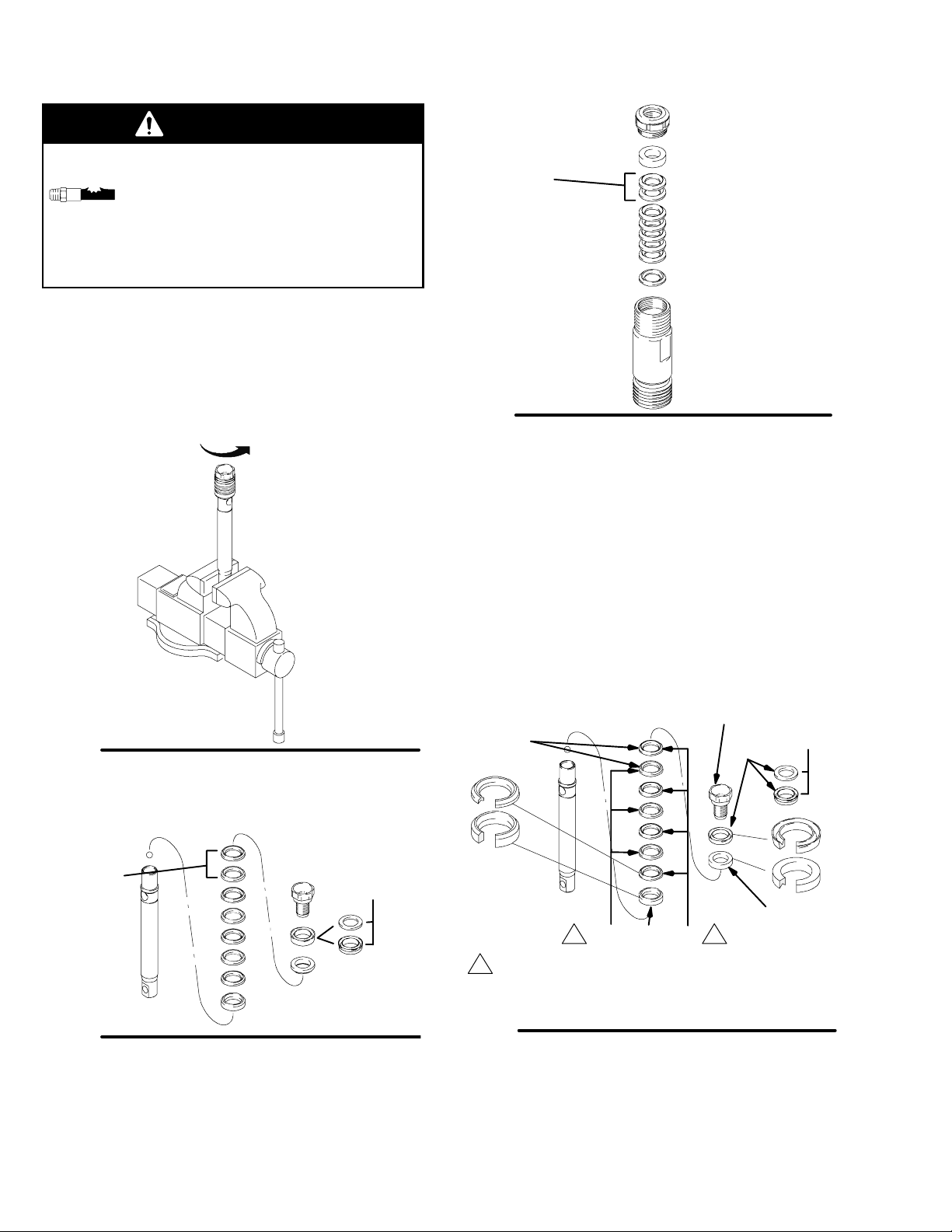
Disassembling the pump
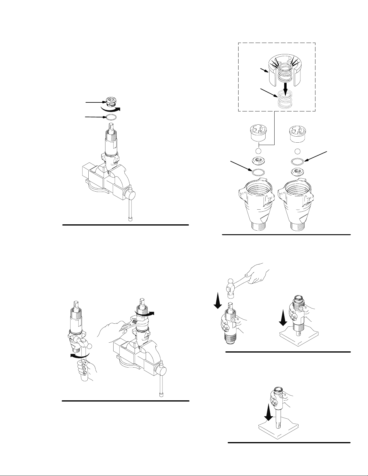
Fig. 1. Remove packing nut (202) and throat adjustment spacer (228).
202
228
Fig. 1
ti2332a
227
(o-ring on
bottom
all except
244957)
Fig. 3
245889, 287946 only
215
236
227
(o-ring on top
244957 only)
7570e
Fig. 2. Unscrew intake valve from cylinder.
Fig. 2
7569A
Fig. 4. Tap piston rod out of cylinder with a hammer or
flip over and tap piston rod out against a bench.
Note: Sleeve may come out
of cylinder with piston rod.
Fig. 4
7571a
Fig. 5. Remove piston rod from sleeve, or remove
sleeve from cylinder.
Fig. 3. Disassemble intake valve. Clean and inspect.
O-ring (227) may require a pick for removal.
Fig. 5
7572A
5309277
Page 6
WARNING
Service
COMPONENT RUPTURE HAZARD
Do not clean or wipe the piston valve
threads. Cleaning the piston valve
threads could destroy the special sealing
patch and cause the piston valve to come loose
during operation, causing pump bursting and
possible serious bodily injury.
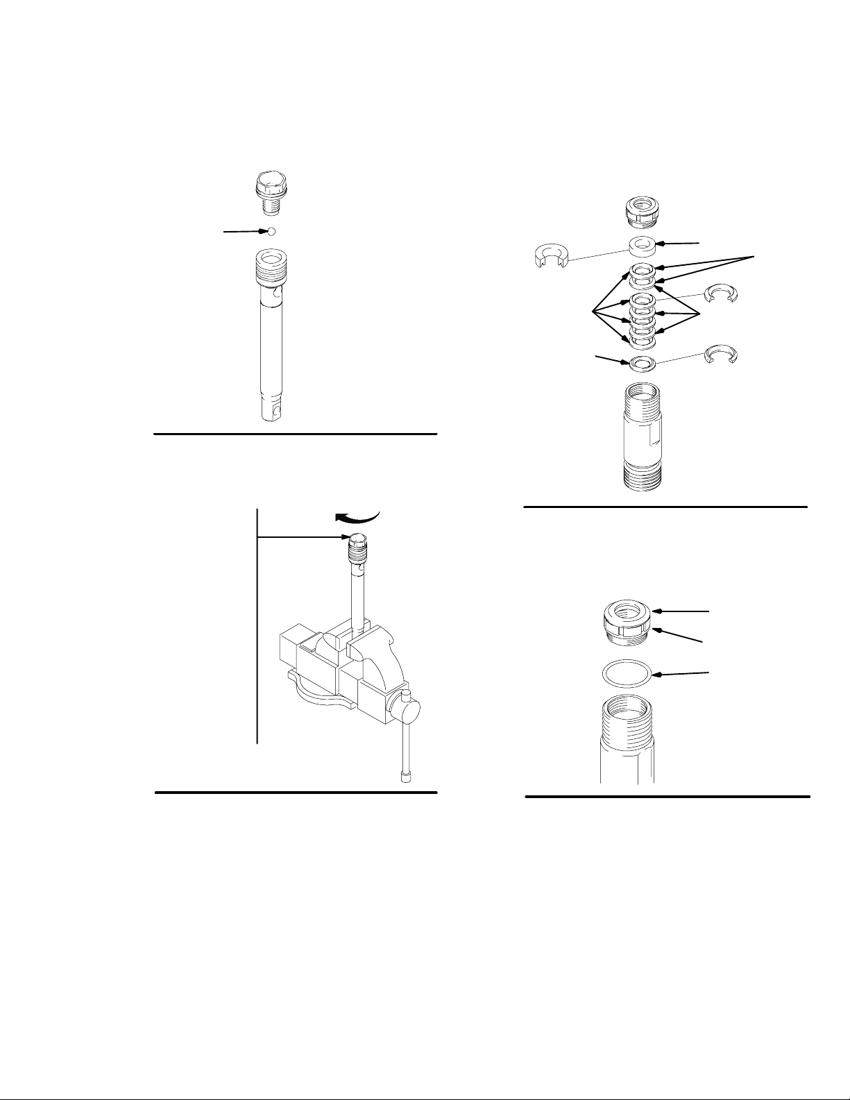
Fig. 6. Unscrew piston valve from piston rod. Clean
and inspect parts. The piston has a special thread
locking/sealing patch. Do not remove the patch. The
patch allows four disassembly/assembly procedures
before it is necessary to apply Loctiter to the threads.
Not
used on
244197
Fig. 8
7573B
Assembling the pump
Fig. 9. Soak all leather packings in SAE 30W oil for 1
hour minimum prior to assembly. Stack male gland
(204) on piston rod. Alternately stack UHMWPE (208)
and leather (218) packings (note orientation) on piston
rod. Install female gland (217). Install piston guide
(216) (note orientation) on piston valve (210). The special sealing patch on piston valve threads is good for
four repackings. Use Loctiter on piston valve threads
after four repackings.
Fig. 6
7576A
Fig. 7. Remove packings and glands from piston rod.
used on
245889,
Not
used on
244197
287946,
287814,
287815
ti3940a
Fig. 7
Fig. 8. Remove throat packings and glands from cylinder. Discard throat packings and glands.
Not
used on
244197
1 1
218 208
204
1
244954, 246257, 245889; 208 and 218 are 203
and 223, respectively. 287946; 208 and 218 are
203 and 209, respectively.
210
216
Fig. 9
Note: Pump 287814 & 287815 do not use leather
packings in piston stack. Alternately stack blue
(208) and brown (218) packings on these pumps.
used on
245889,
287946,
287814,
287815
217
7574c
6 309277
Page 7
Service
Fig. 10. Install ball (206) in piston rod. If Loctiter is applied to piston valve threads, ensure that none gets on
ball.
206
Fig. 10
7575A
Fig. 11. Tighten piston valve to piston rod as specified:
Fig. 12. Soak all leather packings in SAE 30W oil for 1
hour minimum prior to assembly. Place male gland
(204) in cylinder. Alternately stack UHMWPE (203) and
leather packings (223) (note orientation). Place female
gland (224) in top of cylinder. Seat packings.
224
Not
used on
244197
223
203
204
Fig. 12
7573B
Torque to 27 +/--3 ft-lb
(244197)
Torque to 55 +/--3 ft-lb
(244224, 244201,
287814, 287815)
Torque to 190 +/-- 10 ft--lb
(244957)
Torque to 120 +/-- 6 ft-lb
(244954, 246257, 245889,
287946, 277068, 248736,
248971)
Fig. 11
7576A
Fig. 13. Install seal (201) into packing nut (202). Install
throat adjustment spacer (228) onto packing nut.
Loosely install packing nut into cylinder.
201
202
228
ti2333a
Fig. 13
7309277
Page 8
Service
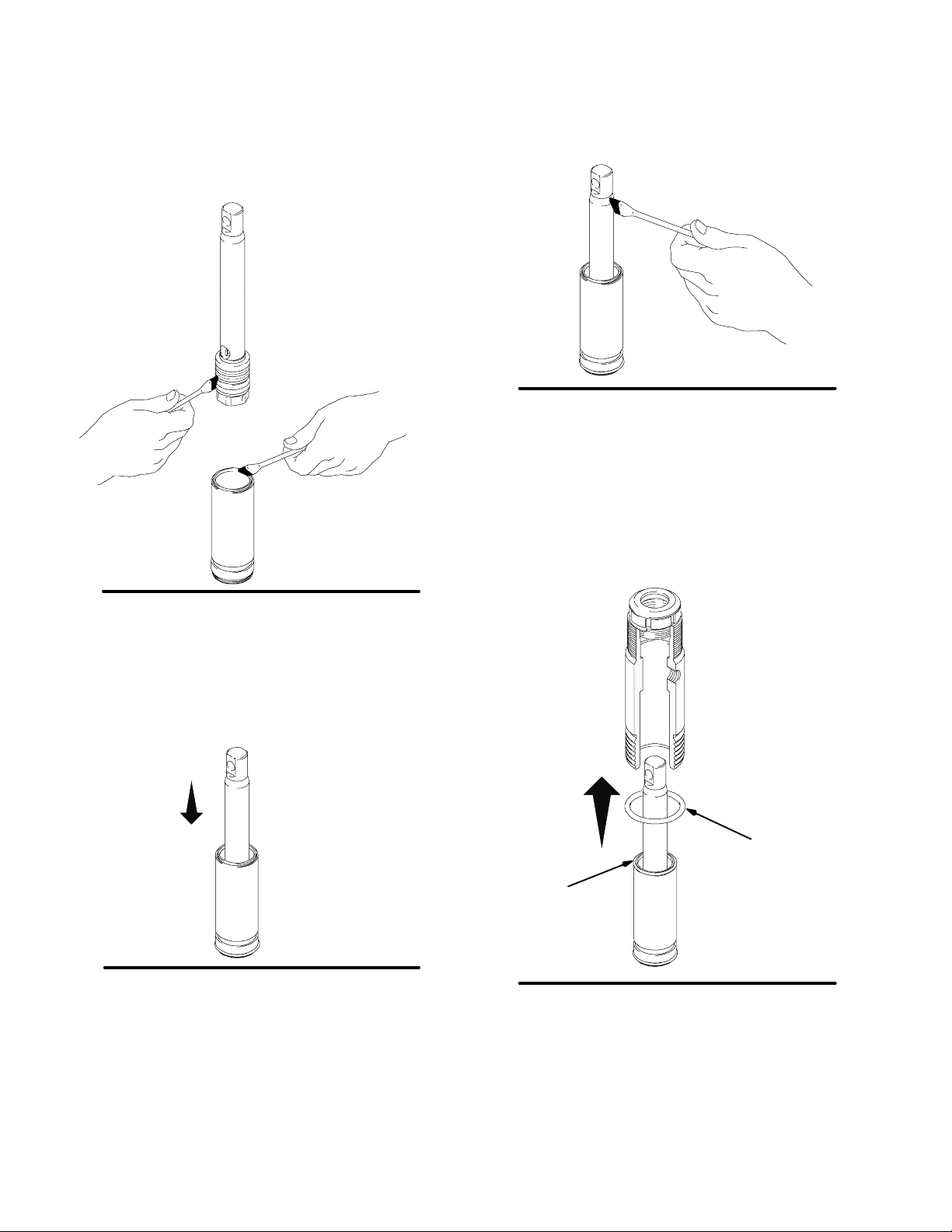
Fig. 14. Grease piston packings and sleeve top edge.
Fig. 16. Grease top inch or two of piston rod that will
go through the cylinder throat packings.
Fig. 16
7579A
Fig. 17. Grease o-ring (221) and place on sleeve. Slide
sleeve/piston rod assembly into bottom of cylinder. Replace o-ring (207) if desired.
Note: O-ring (207) is not required for safe pump operation.
Fig. 14
Fig. 15. Carefully slide piston assembly into top of
sleeve.
Fig. 15
7578A
7577A
Fig. 17
207
221
7582A
8 309277
Page 9
Service
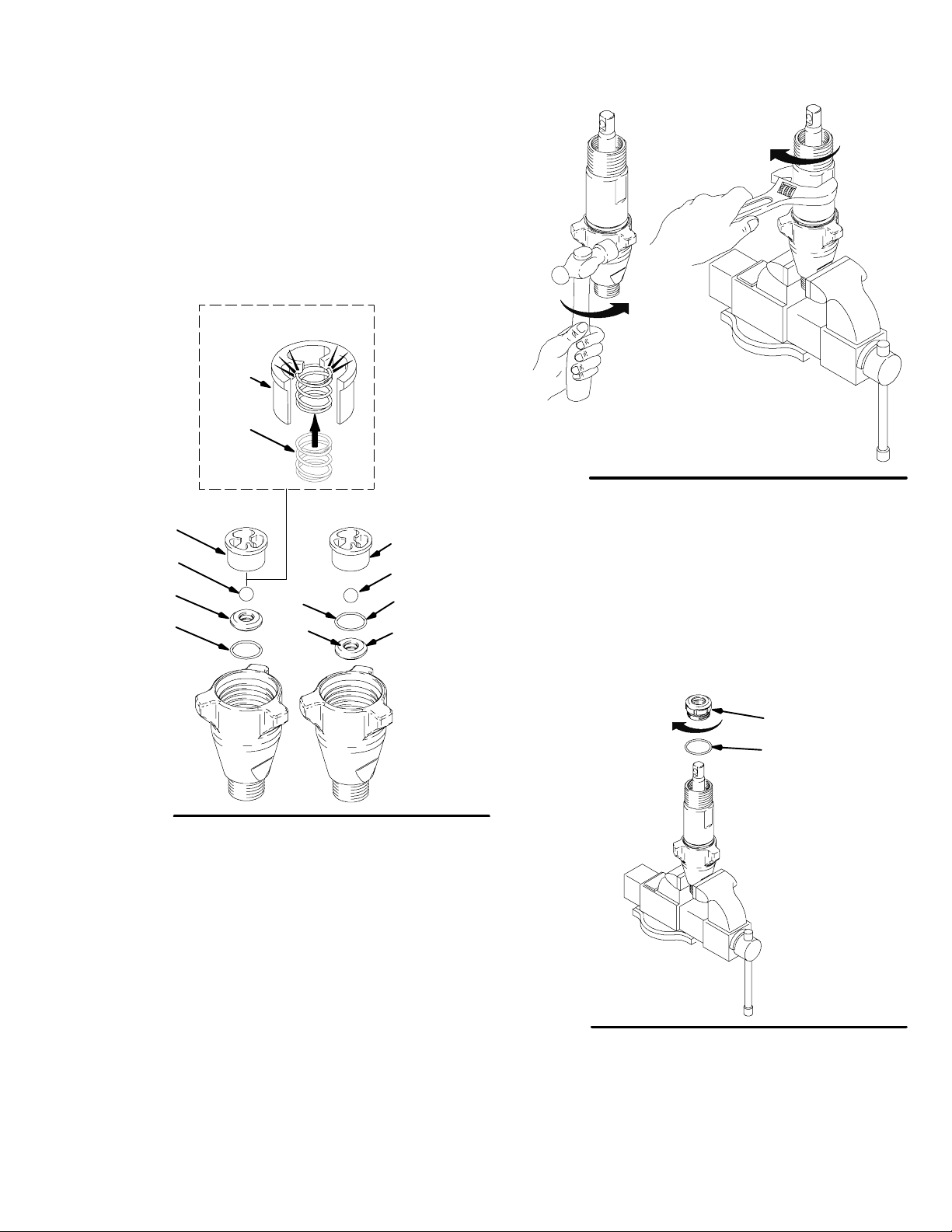
Fig. 18. Reassemble intake valve with new o-ring
(227), seat (212) and ball (214). Seat may be flipped
over and used on other side. Clean seat thoroughly.
Snap intake spring (236) into place inside ball guide
(215).
Spring (236), for model 287946, is optional and not
included with the pump.
245889, 287946 only
215
236
215
214
212
227
(o-ring on
bottom
all except
244957)
Fig.18
Fig. 19. Install intake valve on cylinder. If a wrench is
used torque as follows:
67 +/--5 ft-lb (model 244197)
80 +/--5 ft--lb (models 244201, 244224, 245904)
200 +/--10 ft--lb (models 244954, 246257, 245889,
287946, 277068, 248736, 248971)
200 +/--15 ft--lb (model 244957, 287814, 287815)
If a wrench is not used, be sure intake valve is bottomed out against cylinder.
227
227
215
214
227
212
(o-ring
on top
244957
only)
7570c
Fig. 19
Fig. 20. Torque seal and packing nut (202) down onto
throat adjustment spacer (228) to 100 +/--10 in-lb (75
+/--5 in-lb for 246257) (140+/--10 in--lb for 287814,
287815).
Remove throat adjustment spacer (228) when pump
packings begin to leak after much use. Then tighten
packing nut down until leakage stops or lessens. This
allows approximately 100 gallons of additional operation before a repacking is required.
202
228
ti2332a
Fig. 20
7569A
9309277
Page 10

Repair When Pump Is On The Sprayer
A
WARNING
SKIN INJECTION HAZARD
To reduce the risk of serious injury,
whenever you are instructed to relieve
pressure, follow the Pressure Relief
Procedure on page 4.
Fig. 1. Remove intake valve.
Service
Fig. 2. Use screwdriver to push retaining spring up and
push pin out.
Fig. 1
7673A
Fig. 2
Fig. 3. Disassemble intake valve. Clean and inspect.
O-ring (227) may require a pick for removal.
227
227
(o-ring on
bottom
all except
244957)
Fig. 3
(o-ring on top
244957
only)
7674A
7570
10 309277
Page 11

Service
Fig. 4. Remove piston rod and sleeve.
Fig. 4
7746A
Fig. 4. Invert piston rod and sleeve and pound on hard
surface until piston rod comes out of sleeve.
Fig. 7. Invert piston rod and insert into cylinder to force
out throat packings.
Fig. 5
Fig. 6. Remove packing nut (202)
Fig. 6
202
7572A
7726A
Fig. 7
Fig. 8. Insert piston rod into cylinder with pin hole up
and piston valve down. Insert pin into piston rod and
crank shaft.
7675A
Fig. 8
7747A
11309277
Page 12

Service
Fig. 9. Remove piston valve from piston rod with a
wrench.
Fig. 9
7748A
Fig. 11. Soak all leather packings in SAE 30W oil for 1
hour minimum prior to assembly. Stack male gland
(204). Alternately stack UHMWPE (203) and leather
(223) packings (note orientation). Install female gland
(224). Install seal (201) and packing nut (202) and
throat adjustment spacer (228).
224
Not
used on
244197
201
203
223
228
202
204
Fig. 10. Remove pin and piston rod from cylinder.
Fig. 10
7675A
7573B
7581A
Fig. 11
Fig. 12. Remove packings and glands from piston rod.
used on
245889,
287946,
287814,
287815
Not
used on
244197
Fig. 12
ti3939a
12 309277
Page 13

Service
Fig. 13. Soak all leather packings in SAE 30W oil for 1
hour minimum prior to assembly. Stack male gland
(219) on piston rod. Alternately stack UHMWPE (208)
and leather (218) packings (note orientation) on piston
rod. Install female gland (217). Install piston guide
(216) (note orientation) on piston valve (210). The special sealing patch on piston valve threads is good for
four repackings. Use Loctiter on piston valve threads
after four repackings.
used on
219
217
245889,
287946,
287814,
Not
287815
used on
244197
216
210
1
218
244954, 246257, 245889; 208 and 218 are 203 and
1
223, respectively. 287946; 208 and 218 are 203
and 209, respectively.
208
1
ti3941a
Fig. 13
Note: Pump 287814 & 287815 do not use leather
packings in piston stack. Alternately stack blue
(208) and brown (218) packings on these pumps.
Fig. 15. Grease piston packings and sleeve top edge.
Fig. 15
7578A
Fig. 16. Carefully slide piston assembly into top of
sleeve. Assure u-cup is not rolled over or damaged.
Fig. 10. Install ball (206) in piston rod. If Loctiter is applied to piston valve threads, ensure that none gets on
ball. Install piston valve on piston rod.
Torque as follows:
27 +/--3 ft-lb (for model 244197)
55 +/--3 ft-lb (for models 244224, 244201, 245904,
287814, 287815)
120 +/-- 6 ft-lb (for models 244954, 246257, 245889,
287946, 277068, 248736, 248971)
190 +/--10 ft--lb (for model 244957)
206
Fig. 14
7575A
Fig. 16
7577A
Fig. 17. Grease top inch or two of piston rod that will
go through the cylinder throat packings.
Fig. 17
7579A
13309277
Page 14

Service
Fig. 18. Grease o-ring (221) and place on sleeve. Slide
sleeve/piston rod assembly into bottom of cylinder. Replace o-ring (207) if desired.
Note: O-ring (207) is not required for safe pump operation.
207
7750A221
Fig. 18
Fig. 20. Use screwdriver to push retaining spring up.
Fig. 20
Note: Make sure retaining ring falls into slot.
7674B
Fig. 20. Torque seal and packing nut (202) down onto
throat adjustment spacer (228) to 100 +/--10 in-lb (75
+/--5 in-lb for 246257) (140 +/--10 in-lb for 287814,
287815).
Remove throat adjustment spacer (228) when pump
packings begin to leak after much use. Then tighten
packing nut down until leakage stops or lessens. This
allows approximately 100 gallons of additional operation before a repacking is required.
202
Fig. 19
7726A
Fig. 21. Push in pin.
Fig. 21
7675A
14 309277
Page 15

Service
Fig. 22. Reassemble intake valve with new o-ring
(227), seat (212) and ball (214). Seat may be flipped
over and used on other side. Clean seat thoroughly.
Spring (236), for model 287946, is optional and not
included with the pump.
245889, 287946 only
215
236
227
227
(o-ring on
bottom
all except
244957)
(o-ring on top
244957 only)
Fig. 23. Install intake valve on cylinder. Torque:
67 +/--5 ft-lb (model 244197)
80 +/--5 ft-lb (model 244224, 244201, 245904)
200+/--10 ft-lb (model 244954, 246257, 245889,
287946, 244957, 248971, 248736, 277068, 287814,
287815)
Fig. 23
7678A
Fig. 22
7570d
15309277
Page 16

V-Maxt UHWMPE,
brown on
287814 & 287815
Pump 245889
Service
Cross Sectional Reference
224
223
Leather
205
222
201
202
228
203
204
V-Maxt UHWMPE, blue
221
220
207
See Parts
112589, 189587
Pump 245889, 287946
219
218
3
Leather
210
221
215
212
227
See Parts
15D158, 118600
Spring (236), for model 287946, optional ,
not included with the pump
1
Fig 24
Technical Data
Maximum working pressure
All except 244957 3600 psi (250 bar, 24.8 MPa).................
244957 4000 psi (276 bar, 27.6 MPa)..........................
Fluid inlet size
244224, 244197, 3/4 npt(m).................................
244201, 244954, 246257, 245889, 287946, 245904,
248736, 248971, 287814, 287815 1 npsm(m)...................
244957 1-1/4 npt(m)........................................
Pump 244197
206
2
208
217
V-Maxt UHWMPE, blue
216
214
213
1
(227 on top of 212 244957)
(203 on 244954, 246257, 245889, 287946)2
(223 on 244954, 246257, 245889)3
(209 on 287946)
Fluid outlet size
244197 1/4 npt(f)244224, 244201,............................
244954, 246257, 245904, 248971
248736, 287814, 287815 3/8 npt(f)............................
244957, 245889, 287946 (manifold) 1/2 npt(f)...................
Wetted parts stainless steel, PTFE,...........................
leather, nylon, zinc-plated carbon steel, tungsten carbide, chrome
plating, acetal, polyethylene
NOTE: LoctiteR is a registered trademark of the Loctite Company.
7683C
16 309277
Page 17

Model 244197, Series A
Parts -- Pump 244197
Ref
No. Part No. Description Qty.
201 179810 SEAL, throat 1
202 193046 NUT , packing 1
203* 192692 V-PACKING, throat, 3
V-Maxt UHMWPE, blue
204* 178942 GLAND, male, throat 1
205 243346 CYLINDER, pump
206* 105444 BALL, sst, 0.3125 in. 1
207* 156593 PACKING, o-ring 1
208* 192693 V-PACKING, piston 3
V-Maxt UHMWPE, blue
210 239932 VALVE, piston 1
212† 239922 KIT, seat, carbide 1
includes 214 and 227
213 195892 VALVE, intake (foot)
214*† 105445 BALL, sst, 0.5000 in. 1
215 192624 GUIDE, ball 1
216* 196758 Guide, piston 1
217* 178969 GLAND, female, piston 1
218* 178939 V-PACKING, leather, piston 2
219* 196880 GLAND, male 1
220 240521 SLEEVE, cylinder 1
221* 108526 O-RING, PTFE 2
222 248206 ROD, piston 1
223* 178940 V--PACKING, leather, throat 2
224* 178943 GLAND, female 1
225 196176 ADAPTER, nipple, 1
227*† 107079 PACKING, o-ring 1
228 158776 SPACER, throat adjustment o--ring 1
*223
201
202
228
224*
203*
204*
225
205
*208
†*214
221*
222
219*
218*
217*
216*
206*
210
215
* These parts are also included in Repair Kit 248212,
which may be purchased separately.
† These parts are also included in Carbide Seat Kit
239922, which may be purchased separately.
207*
221*
220
212†
†*227
213
TI0716c
17309277
Page 18

Parts -- Pumps 244224, 244201, 245904
Models 244224, Series A; 244201, Series A; 245904, Series A
Ref
No. Part No. Description Qty.
201 183171 PLUG 1
202 193032 NUT, packing 1
203* 193124 V-PACKING 4
V-Max t UHMWPE, blue
204* 183176 GLAND, packing, male, throat 1
205 CYLINDER, pump
196754 Pump 244201, 245904 1
243347 Pump 244224 1
206* 101947 BALL, sst, 0.375 in. 1
Pump 244224, 244201
116327 BALL, ceramic, 0.375 in. 1
Pump 245904
207* 156633 PACKING, o-ring 1
208* 193125 V-PACKING, piston 4
V-Max t UHMWPE, blue
210 240150 VALVE, piston 1
212† 244199 SEAT, carbide (196866) 1
Pump 244224, 244201
includes 214 and 227
244571 SEAT, carbide (197470) 1
Pump 245904
includes 214 and 227
213 HOUSING, intake (foot)
196753 Pump 244201, 245904 1
195894 Pump 244224 1
214*† 102972 BALL, sst, 0.875 in. 1
Pump 244224, 244201
111453 BALL, ceramic, 0.75 in. 1
Pump 244409, 245904
215 GUIDE, ball
193027 Pump 244224 1
196967 Pump 244201, 245904 1
216* 196757 GUIDE, piston 1
217* 183185 GLAND, female, piston 1
218* 183174 V-PACKING, leather, piston 3
219* 183178 GLAND, packing, male 1
220 240525 SLEEVE, cylinder 1
221* 107098 PACKING, o-- ring 2
222 ROD, piston
241285 Pump 245904 1
288479 Pump 244224 1
241285 Pump 244201 1
223* 183175 V-PACKING, leather, throat 3
224* 183177 GLAND, packing, female 1
225 162485 NIPPLE, adapter, 3/8 npt x 3/8 npsm 1
227*† 108526 PACKING, o-ring 1
228 C20987 SPACER, throat adjustment o--ring 1
* These parts are also included in Repair Kit 248213 (pump
244224, 244201) or Repair Kit 244200 (pump 245904),
which may be purchased separately.
† These parts are also included in Carbide Seat Kit 244199
(pump 244224, 244201) or Carbide Seat Kit 244571
(pump 245904), which may be purchased separately.
*203
201
202
228
224*
223*
204*
225
205
207*
221*
220
*218
†*214
†*227
221*
222‡
219*
208*
217*
216*
206*
210
215
212†
213
TI0717d
18 309277
Page 19

*
Parts -- Pump 244954
Model 244954, Series A
Ref
No. Part No. Description Qty.
201 112590 PLUG 1
202 189589 NUT , packing 1
203* 198701 V-PACKING 8
V-Maxt UHMWPE, blue
204* 15G658 GLAND, packing, male 1
205 244974 CYLINDER, pump 1
206* 107203 BALL, sst, 0.5625 in. 1
207* 160325 PACKING, o-ring 1
210 240580 VALVE, piston 1
212† 240918 SEAT, carbide 1
includes 214 and 227
213 198121 HOUSING, intake (foot) 1
214*† 107167 BALL, sst, 1.000 in. 1
215 198505 GUIDE, ball 1
216* 198303 GUIDE, piston, plastic 1
217* 198765 GLAND, female, piston, steel 1
219 189585 GLAND, packing, male, steel 1
220 244975 SLEEVE, cylinder 1
221* 108822 PACKING, o-ring 2
222 287141 ROD, piston 1
223* 198718 V-PACKING, leather 6
224* 15G657 GLAND, packing, female 1
225 116756 NIPPLE, elbow, 45_ 1
227*† 107098 PACKING, o-ring 1
228 157195 SPACER, throat adjustment o-ring 1
236 233698 SPRING, intake 1
203*
201
202
228
224*
223*
204*
222‡
225
205
207
221*
220
221*
236
215
* These parts are also included in Repair Kit 246341,
which may be purchased separately.
† These parts are also included in Carbide Seat Kit
240918, which may be purchased separately.
203*
217*
216*
206*
210
219*
223*
†*214
†*227
212†
213
TI1308d
TI1308c
19309277
Page 20

Parts -- Pump 244957
Model 244957, Series A
Ref
No. Part No. Description Qty.
201
202
201 196362 PLUG 1
202 196361 NUT , packing 1
203* 197468 V-PACKING (Throat) 4
V-Maxt UHMWPE, blue
204 * 197372 GLAND, packing, male 2
205 244977 CYLINDER, pump 1
206* 101822 BALL, sst, 0.625 in. 1
207* 160258 PACKING, o-ring 1
208* 197469 V-PACKING (Piston) 4
V-Maxt UHMWPE, blue
210 244454 VALVE, piston 1
212† 244960 SEAT, carbide 1
includes 214 and 227
213 196357 HOUSING, intake (foot) 1
214*† 102973 BALL, sst, 1.25 in. 1
215 196363 GUIDE, ball 1
216* 196928 GUIDE, piston 1
217* 197354 GLAND, female, piston 1
218* 184305 V-PACKING, leather, piston 3
219* 196925 GLAND, packing, male 1
220 287557 SLEEVE, cylinder 1
221* 106259 PACKING, o--ring 2
222 287558 ROD, piston 1
223* 184304 V-PACKING, leather, throat 3
224* 197368 GLAND, packing, female 1
225 116755 NIPPLE, elbow, 45_ 1
227*† 104537 PACKING, o-ring 1
228 160721 SPACER, throat adjustment o--ring 1
* These parts are also included in Repair Kit 244958,
which may be purchased separately.
† These parts are also included in Carbide Seat Kit
244960, which may be purchased separately.
*203
*208
228
224*
223*
204*
222
219*
218*
217*
*216
225
205
207*
221*
220
‡
221*
215
†*214
†*227
212†
213
20 309277
206*
210
TI1317b
Page 21

Parts -- Pump 245889
Model 245889, Series B
Ref
No. Part No. Description Qty.
201 112590 PLUG 1
202 189589 NUT , packing 1
203* 198701 V-PACKING 8
V-Maxt UHMWPE, blue
204* 15G658 GLAND, male, throat 1
205 245888 CYLINDER, pump 1
206 118601 BALL, ceramic, 0.5625 in. 1
207* 160325 PACKING, o-ring 1
210 240580 VALVE, piston 1
212† 245885 SEAT, carbide 1
includes 214 and 227
213 15A303 HOUSING, intake (foot) 1
214† 118602 BALL, ceramic, 0.875 in. 1
215 15D158 GUIDE, ball 1
216* 112589 SEAL, U-cup 1
217* 198765 GLAND, female, piston, steel 1
219 189585 GLAND, packing, male, steel 1
220 240921 SLEEVE, cylinder 1
221* 108822 PACKING, o-ring 2
222 245886 ROD, piston 1
223* 198718 V-PACKING, leather, piston 6
224* 15G657 GLAND, packing, female 1
227*† 107098 PACKING, o-ring 1
228 157195 SPACER, throat adjustment o-ring 1
236 118600 SPRING, compression 1
237 189587 WASHER, back-up 1
* These parts are also included in Repair Kit 245819,
which may be purchased separately.
203*
201
202
228
224*
223*
204*
*223
1
*216
237
220
221*
222
219*
203*
217*
206
210
† These parts are also included in Carbide Seat Kit
245885, which may be purchased separately.
205
207*
221*
215
236
†214
212†
†*227
213
ti2086c
21309277
Page 22

Parts -- Pump 287946
Model 287946, Series A
Ref
No. Part No. Description Qty.
201 112590 PLUG 1
202 189589 NUT, packing 1
203* 193722 V-PACKING 8
V-Maxt UHMWPE, blue
204* 15G658 GLAND, male, throat 1
205 15G437 CYLINDER, pump 1
206 118601 BALL, ceramic, 0.5625 in. 1
207* 160325 PACKING, o-ring 1
209* 112591 PACKING, vee, leather 3
210 249177 VALVE, piston 1
212† 245885 SEAT, carbide 1
includes 214 and 227
213 15A303 HOUSING, intake (foot) 1
214† 118602 BALL, ceramic, 0.875 in. 1
215 15D158 GUIDE, ball 1
216* 119636 SEAL, U-cup 1
217* 189588 GLAND, female, piston, steel 1
219 189585 GLAND, packing, male, steel 1
220 248979 SLEEVE, cylinder 1
221* 108822 PACKING, o-ring 2
222 288103 ROD, piston 1
223* 112591 V-PACKING, leather, piston 3
224* 15G657 GLAND, packing, female 1
227*† 107098 PACKING, o-ring 1
228 157195 SPACER, throat adjustment o-ring 1
236 118600 SPRING, compression 1
optional, not included with the pump
237 15F183 WASHER, back-up 1
* These parts are also included in Repair Kit 287945,
which may be purchased separately.
† These parts are also included in Carbide Seat Kit
245885, which may be purchased separately.
It is recommended that the check valve be repaired
at the same time as the pump. See manual 313773
and Kit 258650.
*203
201
202
228
224*
223*
204*
205
207*
221*
*209
1
*216
237
†214
†*227
220
221*
222
219*
203*
217*
206
210
215
236
212†
213
22 309277
ti2086c
Page 23

*
*
*
*
Parts -- Pump 246257
Model 246257, Series A
Ref
No. Part No. Description Qty.
201 112590 PLUG 1
202 189589 NUT, packing 1
203* 198701 V-PACKING 8
V-Maxt UHMWPE, blue
204* 15G658 GLAND, male, throat 1
205 245413 CYLINDER, pump 1
206* 107203 BALL, sst, 0.5625 in. 1
207* 160325 PACKING, o-ring 1
210 240580 VALVE, piston 1
212† 240918 SEAT, carbide 1
includes 214 and 227
213 198219 HOUSING, intake (foot) 1
214*† 107167 BALL, sst, 1.000 in. 1
215 193391 GUIDE, ball 1
216* 198303 GUIDE, piston, plastic 1
217* 198765 GLAND, female, piston, steel 1
219 189585 GLAND, packing, male, steel 1
220 240921 SLEEVE, cylinder 1
221* 108822 PACKING, o-ring 2
222 249000 ROD, piston 1
223* 198718 V-PACKING, leather, piston 6
224* 15G657 GLAND, packing, female 1
227*† 107098 PACKING, o-ring 1
228 157195 SPACER, throat adjustment o-ring 1
236 233698 SPRING, intake 1
* These parts are also included in Repair Kit 246341,
which may be purchased separately.
† These parts are also included in Carbide Seat Kit
240918, which may be purchased separately.
*203
201
202
228
224*
223*
204*
205
*223
1
*216
†*214
†*227
221
222
219
203
217
206*
210
236
215
212†
213
207*
221*
220
23309277
Page 24

*
Parts -- Pump 287815
Model 287815, Series A
Ref
No. Part No. Description Qty.
201* 112590 PLUG 1
202 189589 NUT, packing 1
203* 198701 V-PACKING 8
V-Maxt UHMWPE, blue
204* 15G658 GLAND, male, throat 1
205 249532 KIT , CYLINDER, pump 1
206* 107203 BALL, sst, 0.5625 in. 1
207* 160325 PACKING, o-ring 1
210 249177 VALVE, piston 1
212† 240918 SEAT, carbide 1
includes 214 and 227
213 198219 HOUSING, intake (foot) 1
214*† 107167 BALL, sst, 1.000 in. 1
215 198505 GUIDE, ball 1
216* 119636 WIPER, piston 1
217* 189588 GLAND, female, piston, steel 1
219* 189585 GLAND, packing, male, steel 1
220 287817 SLEEVE, cylinder 1
221* 108822 PACKING, o-ring 2
222 287816 ROD, piston 1
223* 198718 V-PACKING, leather, piston 3
224* 15G657 GLAND, packing, female 1
227*† 107098 PACKING, o-ring 1
228* 157195 SPACER, throat adjustment o-ring 1
236 233698 SPRING, intake 1
237* 15F183 WASHER, backup 1
238* 15F875 V--PACKING, piston V-Maxt
UHMWPE, brown 3
* These parts are also included in Repair Kit 287813,
which may be purchased separately.
† These parts are also included in Carbide Seat Kit
240918, which may be purchased separately.
*203
201
202
228
224*
223*
204*
205
207*
221*
238
217*
1
*216
237
†*214
†*227
221
222
219*
203*
206*
210
236
215
212†
213
24 309277
ti2331c
220
Page 25

*
Model 287814 Series A
Parts -- Pump 287814
221
Ref
No. Part No. Description Qty.
201* 112590 PLUG 1
202 189589 NUT, packing 1
203* 198701 V-PACKING 8
V-Maxt UHMWPE, blue
204* 15G658 GLAND, male, throat 1
205 245413 CYLINDER, pump 1
206* 107203 BALL, sst, 0.5625 in. 1
207* 160325 PACKING, o-ring 1
210 249177 VALVE, piston 1
212† 240918 SEAT, carbide 1
includes 214 and 227
213 198219 HOUSING, intake (foot) 1
214*† 107167 BALL, sst, 1.000 in. 1
215 198505 GUIDE, ball 1
216* 119636 WIPER, piston 1
217* 189588 GLAND, female, piston, steel 1
219* 189585 GLAND, packing, male, steel 1
220 249121 SLEEVE, cylinder 1
221* 108822 PACKING, o-ring 2
222 249119 ROD, piston 1
223* 198718 V-PACKING, leather, piston 3
224* 15G657 GLAND, packing, female 1
227*† 107098 PACKING, o-ring 1
228* 157195 SPACER, throat adjustment o-ring 1
236 233698 SPRING, intake 1
237* 15F183 WASHER, backup 1
238* 15F875 V--PACKING, piston V-Maxt
UHMWPE, brown 3
*203
201
202
228
224*
223*
204*
205
207*
238
217*
1
*216
237
†*214
†*227
222
219*
203*
206*
210
236
215
212†
213
* These parts are also included in Repair Kit 287813,
which may be purchased separately.
† These parts are also included in Carbide Seat Kit
240918, which may be purchased separately.
221*
ti2331c
220
25309277
Page 26

*
*
*
*
*
Parts -- Pump 248736
Model 248736, Series A
Ref
No. Part No. Description Qty.
201 112590 PLUG 1
202 189589 NUT, packing 1
203* 198701 V-PACKING 8
V-Maxt UHMWPE, blue
204* 15G658 GLAND, male, throat 1
205 249532 KIT , CYLINDER, pump 1
206* 107203 BALL, sst, 0.5625 in. 1
207* 160325 PACKING, o-ring 1
210 240580 VALVE, piston 1
212† 240918 SEAT, carbide 1
includes 214 and 227
213 198219 HOUSING, intake (foot) 1
214*† 107167 BALL, sst, 1.000 in. 1
215 193391 GUIDE, ball 1
216* 198303 GUIDE, piston, plastic 1
217* 198765 GLAND, female, piston, steel 1
219 189585 GLAND, packing, male, steel 1
220 248980 SLEEVE, cylinder 1
221* 108822 PACKING, o-ring 2
222 249001 ROD, piston 1
223* 198718 V-PACKING, leather, piston 6
224* 15G657 GLAND, packing, female 1
227*† 107098 PACKING, o-ring 1
228 157195 SPACER, throat adjustment o-ring 1
236 233698 SPRING, intake 1
* These parts are also included in Repair Kit 246341,
which may be purchased separately.
† These parts are also included in Carbide Seat Kit
240918, which may be purchased separately.
*203
201
202
228
224*
223*
204*
205
*223
1
*216
†*214
†*227
221
222
219
203
217
206
210
236
215
212†
213
26 309277
207*
221*
220
ti2331a
Page 27

*
*
*
*
*
Parts -- Pump 248971, 277068
Model 248971, Series A; 277068, Series A
Ref
No. Part No. Description Qty.
201 112590 PLUG 1
202 189589 NUT, packing 1
203* 198701 V-PACKING 8
V-Maxt UHMWPE, blue
204* 15G658 GLAND, male, throat 1
205 245413 CYLINDER, pump 1
206* 107203 BALL, sst, 0.5625 in. 1
207* 160325 PACKING, o-ring 1
210 240580 VALVE, piston 1
212† 240918 SEAT, carbide 1
includes 214 and 227
213 198219 HOUSING, intake (foot) 1
214*† 107167 BALL, sst, 1.000 in. 1
215 193391 GUIDE, ball 1
216* 198303 GUIDE, piston, plastic 1
217* 198765 GLAND, female, piston, steel 1
219 189585 GLAND, packing, male, steel 1
220 SLEEVE, cylinder
248979 PUMP, 248971 1
240921 PUMP, 277068 1
221* 108822 PACKING, o-ring 2
222 249000 ROD, piston 1
223* 198718 V-PACKING, leather, piston 6
224* 15G657 GLAND, female 1
227*† 107098 PACKING, o-ring 1
228 157195 SPACER, throat adjustment o-ring 1
236 233698 SPRING, intake 1
* These parts are also included in Repair Kit 246341
which may be purchased separately.
*203
201
202
228
224*
223*
204*
205
*223
1
*216
†*214
†*227
221
222
219
203
217
206
210
236
215
212†
213
† These parts are also included in Carbide Seat Kit
240918, which may be purchased separately.
207*
221*
220
ti2331a
27309277
Page 28

Graco Standard Wa rranty
Graco warrants all equipment referenced in this document which is manufactured by Graco and bearing its name to be free from
defects in materialand workmanship on the date of sale to the original purchaser for use. With the exception of any special, extended,
or limited warranty published by Graco, Graco will, for a period of twelve months from the date of sale, repair or replace any part of the
equipmentdetermined by Graco to be defective. This warranty applies only when the equipment is installed, operated and maintained
in accordance with Graco’s written recommendations.
This warranty does not cover, and Graco shall not be liable for general wear and tear, or any malfunction,damage or wear caused by
faultyinstallation, misapplication,abrasion, corrosion,inadequate or improper maintenance, negligence, accident, tampering, or substitution of non--Graco component parts. Nor shall Graco be liable for malfunction, damage or wear caused by the incompatibility of
Graco equipment with structures, accessories, equipment or materials not supplied by Graco, or the improper design, manufacture,
installation, operation or maintenance of structures, accessories, equipment or materials not supplied by Graco.
This warranty is conditioned upon the prepaid return of the equipment claimed to be defective to an authorized Graco distributor for
verification of the claimed defect. If the claimed defect is verified, Graco will repair or replace free of charge any defective parts. The
equipmentwill be returnedto the originalpurchaser transportationprepaid. If inspection of the equipment does not disclose any defect
in material or workmanship, repairs will be made at a reasonable charge, which charges may include the costs of parts, labor, and
transportation.
THIS WARRANTY IS EXCLUSIVE, AND IS IN LIEU OF ANY OTHER WARRANTIES, EXPRESS OR IMPLIED, INCLUDING BUT
NOT LIMITED TO WARRANTY OF MERCHANTABILITY OR WARRANTY OF FITNESS FOR A PARTICULAR PURPOSE.
Graco’ssole obligationand buyer’s sole remedy for any breach of warranty shall be as set forth above. The buyer agrees that no other
remedy (including,but not limited to, incidentalor consequential damages for lost profits, lost sales, injury to person or property, or any
other incidental or consequential loss) shall be available. Any action for breach of warranty must be brought within two (2) years of the
date of sale.
GRACO MAKES NO WARRANTY, AND DISCLAIMS ALL IMPLIED WARRANTIES OF MERCHANTABILITY AND FITNESS FOR
A PARTICULAR PURPOSE, IN CONNECTION WITH ACCESSORIES, EQUIPMENT, MATERIALS OR COMPONENTS SOLD
BUT NOT MANUFACTURED BY GRACO. These items sold, but not manufactured by Graco (such as electric motors, switches,
hose, etc.), are subject to the warranty,if any, of their manufacturer. Graco will provide purchaser with reasonable assistance in making any claim for breach of these warranties.
In no event will Graco be liable for indirect, incidental, special or consequential damages resulting from Graco supplying equipment
hereunder, or the furnishing, performance, or use of any products or other goods sold hereto, whether due to a breach of contract,
breach of warranty, the negligence of Graco, or otherwise.
FOR GRACO CANADA CUST
The parties acknowledge that they have required that the present document, as well as all documents, notices and legal proceedings
entered into, given or instituted pursuant hereto or relating directly or indirectly hereto, be drawn up in English. Les parties reconnaissent avoir convenu que la rédaction du présente document sera en Anglais, ainsi que tous documents, avis et procédures judiciaires
exécutés, donnés ou intentés à la suite de ou en rapport, directement ou indirectement, avec les procedures concernées.
OMERS
ADDITIONAL WARRANTY COVERAGE
Graco does provide extended warranty and wear warranty for products described in the “Graco Contractor Equipment Warranty
Program”.
TO PLACE AN ORDER, contact your Graco distributor, or call this number to identify the distributor closest to you:
1--800--690--2894 Toll Free
All written and visual data contained in this document reflect the latest product information available at the time of publication.
Graco reserves the right to make changes at any time without notice.
Original Instructions. This manual contains English; MM 309277
28 309277
Graco Headquarters: Minneapolis
International Offices: Belgium, China, Japan, Korea
GRACO INC. P.O. BOX 1441 MINNEAPOLIS, MN 55440--1441
Copyright 2000, Graco Inc. is registered to ISO 9001
www.graco.com
Rev. 08/2011
 Loading...