

Page 1
Instructions
Parts
Pressure
Compensating Valve
The pressure compensating valve minimizes the effects of pressure changes from the fluid source and
reduces or eliminates material flow variances caused by piston pump changeover and unbalanced
pump lowers. Eliminating surge variations adds consistency to the application process.
The pressure compensating valve is used:
in applications requiring a consistent bead size throughout the dispense cycle.
to overcome the initial surge of material when the dispense valve is opened in a deadhead system.
with single component materials when viscosities are generally greater than 100,000 cps.
Read warnings and instructions.
See page 2 for compensator part nos., ratios,
and working pressures.
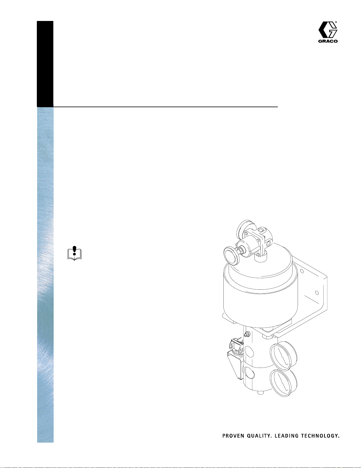
309133C
Model 243656 Shown
TI0368B
GRACO INC.ąP.O. BOX 1441ąMINNEAPOLIS, MNą55440-1441
Copyright 2000, Graco Inc. is registered to I.S. EN ISO 9001
Page 2

Table of Contents
Symbols 3. . . . . . . . . . . . . . . . . . . . . . . . . . . . . . . . . . . . . . . . . . . . . . . . . . . . . . . . . . . . . . . . . . . . . . . . . . . . . . . . . . . . . . . . . . .
Warnings 3. . . . . . . . . . . . . . . . . . . . . . . . . . . . . . . . . . . . . . . . . . . . . . . . . . . . . . . . . . . . . . . . . . . . . . . . . . . . . . . . . . . . . . . . . . .
Compensator Models 2. . . . . . . . . . . . . . . . . . . . . . . . . . . . . . . . . . . . . . . . . . . . . . . . . . . . . . . . . . . . . . . . . . . . . . . . . . . . . . . .
Unpacking and Repacking 6. . . . . . . . . . . . . . . . . . . . . . . . . . . . . . . . . . . . . . . . . . . . . . . . . . . . . . . . . . . . . . . . . . . . . . . . . . . .
Overview 7. . . . . . . . . . . . . . . . . . . . . . . . . . . . . . . . . . . . . . . . . . . . . . . . . . . . . . . . . . . . . . . . . . . . . . . . . . . . . . . . . . . . . . . . . . .
Installation 8. . . . . . . . . . . . . . . . . . . . . . . . . . . . . . . . . . . . . . . . . . . . . . . . . . . . . . . . . . . . . . . . . . . . . . . . . . . . . . . . . . . . . . . . . .
Maintenance 11. . . . . . . . . . . . . . . . . . . . . . . . . . . . . . . . . . . . . . . . . . . . . . . . . . . . . . . . . . . . . . . . . . . . . . . . . . . . . . . . . . . . . . .
Troubleshooting 12. . . . . . . . . . . . . . . . . . . . . . . . . . . . . . . . . . . . . . . . . . . . . . . . . . . . . . . . . . . . . . . . . . . . . . . . . . . . . . . . . . . .
Service 13. . . . . . . . . . . . . . . . . . . . . . . . . . . . . . . . . . . . . . . . . . . . . . . . . . . . . . . . . . . . . . . . . . . . . . . . . . . . . . . . . . . . . . . . . . .
Parts List 16. . . . . . . . . . . . . . . . . . . . . . . . . . . . . . . . . . . . . . . . . . . . . . . . . . . . . . . . . . . . . . . . . . . . . . . . . . . . . . . . . . . . . . . . . .
Wiring Diagram 20. . . . . . . . . . . . . . . . . . . . . . . . . . . . . . . . . . . . . . . . . . . . . . . . . . . . . . . . . . . . . . . . . . . . . . . . . . . . . . . . . . . .
Repair Kits and Accessories 21. . . . . . . . . . . . . . . . . . . . . . . . . . . . . . . . . . . . . . . . . . . . . . . . . . . . . . . . . . . . . . . . . . . . . . . . .
Technical Data 22. . . . . . . . . . . . . . . . . . . . . . . . . . . . . . . . . . . . . . . . . . . . . . . . . . . . . . . . . . . . . . . . . . . . . . . . . . . . . . . . . . . . .
Warranty 24. . . . . . . . . . . . . . . . . . . . . . . . . . . . . . . . . . . . . . . . . . . . . . . . . . . . . . . . . . . . . . . . . . . . . . . . . . . . . . . . . . . . . . . . . .
Graco Phone Number 24. . . . . . . . . . . . . . . . . . . . . . . . . . . . . . . . . . . . . . . . . . . . . . . . . . . . . . . . . . . . . . . . . . . . . . . . . . . . . . .
Compensator Models
Maximum Operating Air
Pressure
Ratio and Type
Part No. Series
243206 A 51:1 , Heated 120V 0.7, 7.0 (100) 23.8 , 238 (3500)
243654 A 51:1 Ambient 0.7, 7.0 (100) 23.8, 238 (3500)
243655 A 23:1 Ambient 0.7, 7.0 (100) 17.2 , 172.4 (2500)
243656 A 23:1, Heated 240 V 0.7, 7.0 (100) 17.2, 172.4 (2500)
243657 A 51:1, Heated 240 V 0.7, 7.0 (100) 23.8, 238 (3500)
243658 A 23:1, Heated 120V 0.7, 7.0 (100) 17.2, 172.4 (2500)
(parts list page)
MPa, bar (psi) MPa, bar (psi)
Maximum Operating Fluid
Pressure
2 309133
Page 3

Symbols
Warning Symbol
WARNING
This symbol alerts you to the possibility of serious
injury or death if you do not follow the instructions.
WARNING
EQUIPMENT MISUSE HAZARD
Equipment misuse can cause the equipment to rupture or malfunction and result in serious injury.
INSTRUCTIONS
This equipment is for professional use only.
Read all instruction manuals, tags, and labels before operating the equipment.
Use the equipment only for its intended purpose. If you are uncertain about usage, call your Graco
distributor.
Do not alter or modify this equipment. Use only genuine Graco parts and accessories.
Caution Symbol
CAUTION
This symbol alerts you to the possibility of damage to
or destruction of equipment if you do not follow the
instructions.
Check equipment daily. Repair or replace worn or damaged parts immediately.
Do not exceed the maximum working pressure stated on the equipment or in the Technical Data
for your equipment. Do not exceed the maximum working pressure of the lowest rated component
in your system.
Use fluids and solvents which are compatible with the equipment wetted parts. Refer to the Tech-
nical Data section of all equipment manuals. Read the fluid and solvent manufacturer’s warnings.
Do not use hoses to pull equipment.
Route hoses away from traffic areas, sharp edges, moving parts, and hot surfaces. Do not expose
Graco hoses to temperatures above 82C (180F) or below –40C (–40F).
Wear hearing protection when operating this equipment.
Do not lift pressurized equipment.
Comply with all applicable local, state, and national fire, electrical, and safety regulations.
309133 3
Page 4
WARNING
FIRE AND EXPLOSION HAZARD
Improper grounding, poor ventilation, open flames or sparks can cause a hazardous condition and result in a fire or explosion and serious injury.
Ground the equipment and the object being sprayed. Refer to Grounding on page 8.
If there is any static sparking or you feel an electric shock while using this equipment, stop spray-
ing/dispensing immediately. Do not use the equipment until you identify and correct the problem.
Provide fresh air ventilation to avoid the buildup of flammable fumes from solvents or the fluid be-
ing sprayed/dispensed.
Keep the spray/dispense area free of debris, including solvent, rags, and gasoline.
Electrically disconnect all equipment in the spray/dispense area.
Extinguish all open flames or pilot lights in the spray/dispense area.
Do not smoke in the spray/dispense area.
Do not turn on or off any light switch in the spray/dispense area while operating or if fumes are
present.
Do not operate a gasoline engine in the spray/dispense area.
TOXIC FLUID HAZARD
Hazardous fluid or toxic fumes can cause serious injury or death if splashed in the eyes or on the skin,
inhaled, or swallowed.
Know the specific hazards of the fluid you are using.
Store hazardous fluid in an approved container. Dispose of hazardous fluid according to all local,
state and national guidelines.
Always wear protective eyewear, gloves, clothing and respirator as recommended by the fluid and
solvent manufacturer.
HOT SURFACE AND FLUID HAZARD
Heated fluid can cause severe burns and can cause equipment surfaces to become very hot.
Wear protective gloves and clothing when operating this equipment in a heated system.
Do not touch the metal heat sink when the surface is hot.
Allow the equipment to cool thoroughly before servicing.
Some heated systems are designed to dispense PUR heated materials. PUR systems are supplied
with ventilation hoods, and require proper ventilation and specially designed system components.
4 309133
Page 5
WARNING
MOVING PARTS HAZARD
Moving parts, such as the air motor piston, can pinch or amputate your fingers.
Keep clear of all moving parts when starting or operating the pump.
Before servicing the equipment, follow the Pressure Relief Procedure on page 10 to prevent the
equipment from starting unexpectedly.
INJECTION HAZARD
Spray from the gun, hose leaks, or ruptured components can inject fluid into your body and cause an
extremely serious injury, including the need for amputation. Splashing fluid in the eyes or on the skin
can also cause a serious injury.
Fluid injected into the skin might look like just a cut, but it is a serious injury. Get immediate medi-
cal attention.
Do not point the spray gun at anyone or at any part of the body.
Do not put hand or fingers over the spray tip.
Do not stop or deflect fluid leaks with your hand, body, glove, or rag.
Do not “blow back” fluid; this is not an air spray gun.
Check the gun diffuser operation weekly.
Be sure the gun trigger safety operates before spraying.
Lock the gun trigger safety when you stop spraying.
Follow the Pressure Relief Procedure on page 10 whenever you: are instructed to relieve pres-
sure; stop spraying; clean, check, or service the equipment; or install or clean the spray tip.
Tighten all the fluid connections before operating the equipment.
Check the hoses, tubes, and couplings daily. Replace worn, damaged, or loose parts immediately.
Permanently coupled hoses cannot be repaired; replace the entire hose.
309133 5
Page 6

Unpacking and Repacking
Unpacking the Product
The pressure compensating valve was carefully packaged for shipment by Graco. When the product arrives, perform the following procedure to unpack the
unit:
1. Inspect the shipping box carefully for shipping
damage. Contact the carrier promptly if damage is
discovered.
2. Unseal the box and inspect the contents carefully.
There should not be any loose or damaged parts.
3. Compare the packing slip against all items included in the container. Any shortages or other
inspection problems should be reported immediately.
4. Store the box and packing materials in a safe
place for future use. Graco recommends that all
packing materials be saved in case the unit needs
to be shipped again.
6 309133
Page 7
Overview
Description
The purpose of the pressure compensating valve is to
provide a consistent flow of sealant and adhesive
material downstream, through a hose, to a dispense
valve and nozzle.
The pressure compensating valve applies a precisely
regulated air pressure to a rolling diaphragm to open a
valve spool. Downstream back pressure is applied to
the opposite end of the spool to push it closed. The
two opposing forces cause the spool to throttle the
material through a tapered valve seat, thereby compensating for any pressure fluctuation.
The area of the spool and the 1” (25.5 mm) stroke of
the spool cause it to displace material. When the
spool extends into the downstream end of the pressure
compensating valve it can provide up to 1.0 cu. inches
of material to compensate for the momentary loss of
supply pressure. When the spool is retracted beyond
the point of shutoff, it will withdraw material from the
downstream end. This causes a relieving effect.
The displacement of the spool is what separates it
from regulators. The inlet pressure is balanced against
the spool, thus making it immune to changes in upstream pressure. The air cylinder (rolling diaphragm)
area versus the area of the end of the spool, give the
pressure compensating valve a power ratio, just as a
reciprocating pump has a power ratio. The Pressure
Compensating Valve is available in 23:1 and 51:1
ratios, ambient or heated models.
Because the inlet pressure is balanced, a low ratio
pressure compensating valve may be used with a high
ratio pump. Optimum operation will be reached by
using the lowest ratio pressure compensating valve to
provide the required pressure.
Operation
The pressure compensating valve is installed with a
precision air regulator for the air cylinder in order to
provide accurate control. It is also installed with inlet
and outlet fluid pressure gauges. To avoid extreme
wear, when dispensing material, do not exceed 300 psi
differential across the pressure compensating valve
(the difference between the inlet and the outlet fluid
pressure gauges).
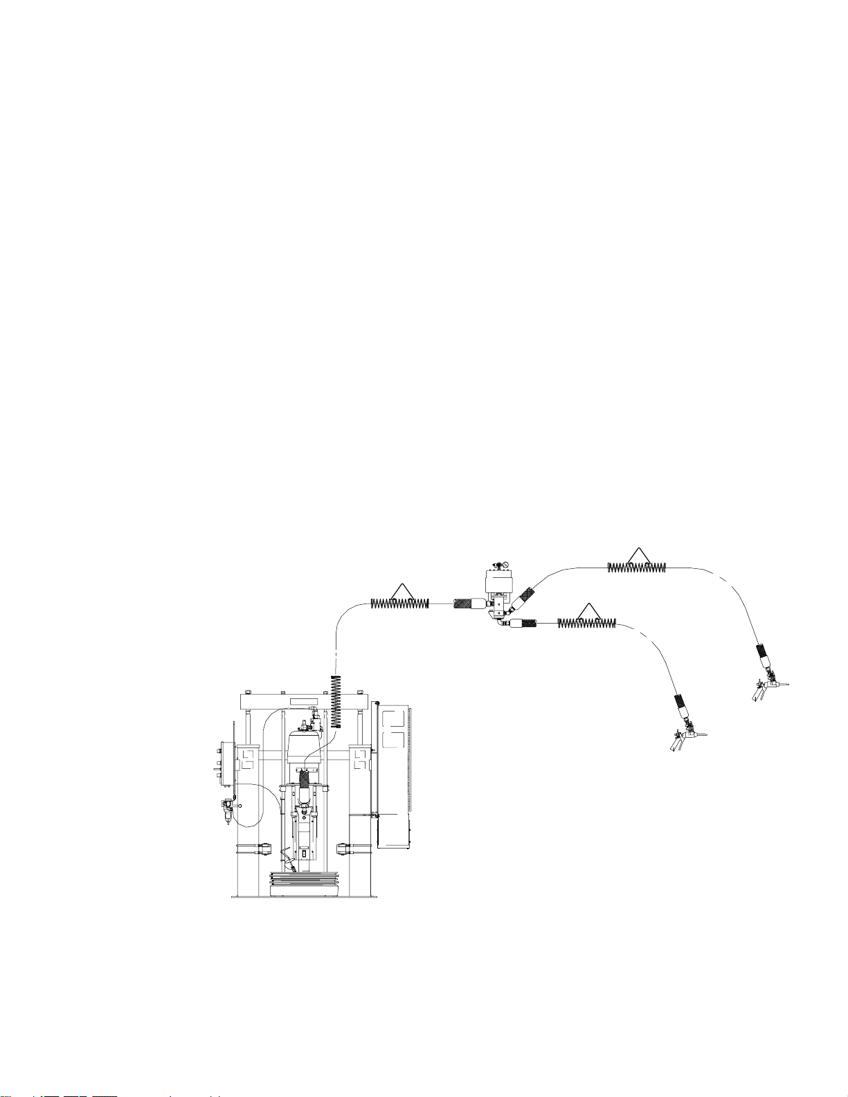
Typical Installation
309133 7
Page 8
Installation
Ground The System
WARNING
FIRE, EXPLOSION, AND ELECTRIC
SHOCK HAZARD
To reduce the risk of fire, explosion, and
serious injury, proper electrical grounding of every part of your system is
essential. Read the warning section,
FIRE AND EXPLOSION HAZARD, on
page 4 and follow the grounding instructions, below.
The following grounding instructions are minimum
requirements for a basic dispensing system. Your
system may include other equipment or objects which
must be grounded. Check your local electrical code
for detailed grounding instructions for your area and
type of equipment. Your system must be connected to
a true earth ground.
1. Pump: ground the pump by connecting a ground
wire and clamp as described in your separate
pump instruction manual.
2. Air compressors and hydraulic power
supplies: ground the equipment according to the
manufacturer’s recommendations.
7. All solvent pails used when flushing: ground
according to local code. Use only metal pails,
which are conductive. Do not place the pail on a
non–conductive surface, such as paper or
cardboard, which interrupts the grounding
continuity.
8. To maintain grounding continuity when
flushing or relieving pressure: hold a metal part
of the gun firmly to the side of a grounded metal
pail, then trigger the gun.
General Information
NOTE: Reference numbers and letters in parentheses
in the text refer to the callouts in Fig. 1.
A pressure compensating valve can be used in manual
and automatic dispensing applications.
WARNING
ELECTROCUTION HAZARD
Installing and servicing this equipment
requires access to parts which could
cause an electric shock or other serious
injury. Have only qualified electricians access the
control assembly.
Location of the Pressure Compensating
Valve
3. Fluid hoses: use only ground fluid hoses with a
maximum of 500 feet (150 m) combined hose
length to ensure grounding continuity. Check the
electrical resistance of your fluid hoses at least
once a week. If your hose does not have a tag on
it which specifies the maximum electrical
resistance, contact the hose supplier or
manufacturer for the maximum resistance limits. If
the hose resistance exceeds the recommended
limits, replace it immediately.
4. Flo–gun: ground the gun by connecting it to a
properly grounded fluid hose and pump.
5. Fluid supply container: ground according to the
local code.
6. Flammable liquids in the dispensing area:
must be kept in approved, grounded containers.
Do not store more than the quantity needed for
one shift.
The pressure compensating valve should be lo-
cated between the supply pump and dispense
valve, as close to the point of disperse as possible.
CAUTION
Downstream hose lengths beyond 15 feet will start to
diminish the valve’s effectiveness in compensating
for surge.
WARNING
PRESSURIZED EQUIPMENT HAZARD
To reduce risk of injury or equipment
damage:
Make sure all material hose connec-
tions are secure.
Do not pressurize the system until
you have verified the system is ready
and it is safe to do so.
8 309133
Page 9

Installation
Installing the Pressure Compensating
Valve
Before mounting the pressure compensating valve,
extra inlet/outlet plugs and insulating wrap (for heated
units only) need to be assembled. There are two inlets
and outlet ports. Decide which are to be used and
plug the others. Completely wrap the steel fluid housing with provided insulation wrap and tape.
To install the pressure compensating valve:
Mount the pressure compensating valve.
Connect the air line.
Connect the inlet and discharging hose.
Air in
37
3. Connect the material supply hose to the pressure
compensating valve’s inlet port (A) and connect
the material discharge hose to the pressure compensating valve’s outlet port (B). See Fig. 1.
NOTE: It is recommended the compensator be
isolated with shutoff valves for air and material inlet/
outlet lines.
WARNING
To reduce the risk of over–pressurizing your system, which could result in component rupture and
cause serious injury, never exceed the specified
maximum incoming air pressure to the pumps (see
the Technical Data in the pump manual).
Pressure Compensator Set Up
1. Ensure that air pressure is supplied to the ram and
pump.
2. For models with heaters, bring the system to the
operating temperature.
A
40
Material In
TI0370B
B
Material Out
Fig. 1
1. Using the attached mounting bracket (40), secure
the pressure compensating valve to a rigid support
or a wall capable of supporting 75 pounds. See
Fig. 1.
2. Connect the air line to the pressure compensating
valve’s regulator (37 ). See Fig. 1.
3. Set the pressure compensating valve’s air regula-
tor to maximum (full open).
4. Place a waste container under material dispense
valve.
5. Slowly increase the supply pump pressure and fill
the entire system.
6. Once the system is fully primed, adjust the supply
pump pressure until the desired, non–regulated,
material flow rate is achieved.
7. Increase the supply pump material pressure by
300 psi.
8. Decrease the pressure compensator air regulator
until the desired flow rate is achieved.
9. Decrease the supply pump pressure until the
material flow surges, then increase the pressure
until the surge is eliminated.
10. Final material flow rate adjustments can now be
done with the pressure compensator air regulator.
11. Record all regulator and material pressures for
future reference.
NOTE: The difference between the inlet and outlet
pressure on the pressure compensating valve should
not exceed 300 psi.
309133 9
Page 10

Installation
To change the differential across the pressure
compensating valve, adjust the precision air regulator pressure up or down to bring the fluid pressure
gauges to within the 300 psi tolerance (obtain a
pressure difference as close as possible to zero
psi).
Adjust the air regulator when the material is being
dispensed.
By increasing the air pressure to the cylinder,
you increase the outlet fluid pressure.
By decreasing the air pressure you decrease
the outlet fluid pressure.
Ensure that the pressure compensating valve’s
piston always floats and does not extend to the end
of its stroke and remain there. Check this by
watching the spool between the air cylinder and the
main body of the pressure compensating valve.
The spool should move down when the supply
pump changes its stroke and move up when
the supply pump pressure is returned to normal.
If the spool does not retract, slightly reduce the
air pressure to the air cylinder. When the
dispense valve is closed the spool will retract
slightly, causing a relieving effect in the dispense hose.
Pressure Relief Procedure
This procedure is described in the instruction manual
that was supplied with your system. Please refer to
that document.
WARNING
The material and equipment will be
hot! To reduce risk of injury, wear eye
protection, gloves and protective clothing
when installing, operating, or servicing
this dispensing system.
WARNING
HIGH PRESSURES CAN CAUSE SERIOUS PERSONAL INJURY. Be sure
to OPEN THE DISPENSE VALVE
DURING SYSTEM HEATUP to allevi-
ate pressure which might occur in the system due
to material expansion.
WARNING
INJECTION HAZARD
The system pressure must be manually
relieved to prevent the system from
starting or spraying accidentally. Fluid
under high pressure can be injected through the
skin and cause serious injury. To reduce the risk of
an injury from injection, splashing fluid, moving
parts, follow the Pressure Relief Procedure
whenever you:
are instructed to relieve the pressure
stop spraying/dispensing
WARNING
MOVING PARTS HAZARD
Follow the Pressure Relief Procedure
in your separate system manual before
checking or repairing the ram or any
other part of the system and when shutting down
the system. Keep hands and fingers away from the
follower plate, fluid pump inlet, and lip of the fluid
container when raising or lowering the ram to
reduce the risk of pinching or amputating hands or
fingers.
During operation, also keep hands and fingers
away from limit switches to reduce the risk of
pinching or amputating hands or fingers.
10 309133
check or service any of the system equipment
install or clean the spray tip/nozzle
Page 11

Maintenance
Table 1 shows the preventive maintenance schedule for the Pressure Compensating Valve.
Table 1. Preventive Maintenance Schedule
Schedule Component Description
Weekly Compensator body
Remove plug to visually inspect grease. If a lot of pumped material is present, disassemble following instructions on page 13. Clean or replace components as needed.
Weekly Lubricate the components
Remove plug to visually inspect grease. If needed, lubricate with Gray Mobilith SCH220
grease.
Daily Spool floats freely
Watch the spool between the air cylinder and the main body of the pressure compensating
valve. The spool should move up and down when the supply pump pressure returns to
normal. If the spool does not retract, slightly reduce the pressure to the air cylinder.
309133 11
Page 12

Troubleshooting
Problem Cause Solution
Outlet material pressure not
consistent.
Outlet pressure builds up while
not dispensing.
Material is leaking externally. Internal seals are worn. Replace seals.
Not enough outlet pressure.
Material pressure gauge readings
do not change when the flow rate
is adjusted.
Plunger does not float Seal is worn. Replace seal.
Air regulator does not display
consistent pressure reading.
Inlet pressure is too low. Adjust inlet pressure from supply
pumps.
Internal throat seals, o–rings and/or
plunger are worn.
Internal throat seals, o–rings and/or
plunger are worn.
Material regulator is not calibrated
correctly.
Supply pumps are set too low or
turned off.
Material gauges are damaged. Replace.
Pressure adjustment range is
exceeded.
Improper regulator setting.
Regulator not functioning properly
Replace seals, inspect, and/or
replace plunger.
Replace seals, inspect, and/or
replace plunger.
See pressure compensator setup on
page 9.
Verify supply.
Calibrate the pressure in a lower
pressure range.
Replace or repair air regulator.
Air is not getting to regulator. Air hose not connected or loose. Attach or tighten air hose to regulator.
12 309133
Page 13

Service
NOTE: Reference numbers and letters in parentheses
in the text refer to the callouts in the figures and the
parts drawing on pages 16–19.
WARNING
EQUIPMENT MISUSE HAZARD
Exercise care when mounting and
handling the Pressure Compensating
Valve to prevent equipment damage or
personal injury.
Disassembly
1. Disconnect all hoses connecting the pressure
compensating valve to the gun and heating units.
2. On heated models, remove insulation wrap.
3. Remove the two bolts (41), washers (42), and nuts
(43) holding mounting bracket (40) to the mounting
plate (14).
13. Remove the two screws (19) securing the heater
cover (23) to the block outlet (11). Remove the
heater cover (23) to access the two screws (20)
securing the heating unit to the block outlet (11).
Remove the screws (20) and washers (21).
14. Carefully remove the cartridge heater (28, 57) and
RTD temperature sensor (27) from the block outlet
(11).
15. Remove the o–ring (10) and throttle adapter (17)
from the opening in the center of the lower compensator body section.
16. Remove the lip seal (9).
17. Carefully inspect the lip seals (9, 45), washers
(21), throttle adapter (17), and o–rings (6, 10) for
wear and weakness. If they are worn or damaged,
replace them.
18. Carefully inspect the piston (8). If it is damaged or
the surface scored, replace it.
4. Remove the two cap screws (25, 56) and two
spacers (13, 55).
5. Carefully remove the air cylinder (1) and the piston
(8) from the compensator body (16) and block
outlet (11).
6. Loosen the adjusting nut (2) while holding piston
(8) on the wrench flats. Remove piston (8) from
the air cylinder (1) by turning piston counterclockwise.
7. Remove the four cap screws (3) holding the
mounting plate (14) to the compensator body (16).
8. Remove the mounting plate (14).
9. Remove the bearing plunger (5) from inside the
compensator body (16).
10. Remove the o–ring (6) from the top groove on the
outside of the bearing plunger (5). Remove the lip
seal (45) located inside the bearing plunger (5).
CAUTION
Use only high temperature synthetic grease or Graco
cartridge no. 115982. Use of any other grease may
result in unit failure or system contamination.
Reassembling the Compensator
1. Generously grease lip seal (9) with high temperature synthetic grease or Graco cartridge no.
115982 (32). Carefully insert the lip seal (9), with
the lips facing down, in the opening located in the
bottom of the compensator body (16).
2. Generously grease the throttle adapter (17) with
high temperature synthetic grease or Graco cartridge no. 115982 (32). Insert the throttle adapter
(17) over the lip seal (9) in the opening on the
bottom of the compensator body (16). Place o–ring
(10) on top of throttle adapter (17).
3. Coat the heater (28, 57) and RTD temperature
sensor (27) with Lubricant Thermal Compound
(31), and insert into their proper locations in the
bottom of the compensator body (16).
11. Remove the lip seal (9) located inside the compensator body (16).
12. Turn the compensator body (16) over. Remove
the four screws (12) holding the top and bottom
halves of the compensator body together.
4. Position the heater (28, 57) and RTD temperature
sensor (27) wires in the slots located in the block
outlet (11).
Allow sufficient lead wire length to be able to
rotate the connector bracket ± 180.
309133 13
Page 14

Service
5. Carefully align the block outlet (11) and compensator body (16) and secure using the four screws
(12). Torque screws (12) to 45 ft-lb. (61 Nm).
6. Secure the heating unit to the block outlet (11)
using the two screws (20) and washers (21).
7. Replace the heater cover (23) and screws (19).
8. Turn the heater over. Generously grease the lip
seal (9) with high temperature synthetic grease or
Graco cartridge no. 115982 (32). Carefully insert
lip seal (9), with the lips facing down, in the center
opening located on the top of the compensator
body (16).
9. Generously grease o–ring (6) with high temperature synthetic grease or Graco cartridge no.
115982 (48). Position it in the groove located
around the outside of the bearing plunger (5).
10. Generously grease rod lip seal (45) with high
temperature synthetic grease or Graco cartridge
no. 115982 (32). Place the lip seal (45), with the
lips facing down, inside the bearing plunger (5).
11. Lightly grease the entire bearing plunger (5) with
high temperature synthetic grease or Graco cartridge no. 115982 (32). Carefully insert the bearing
plunger (5) in the opening on the top of the compensator body (16).
12. Attach the mounting plate (14) to the compensator
body (16) using the four cap screws (3). See Fig 1.
which shows the correct orientation of the mounting plate (14) to the compensator body (16).
13. On heated models, wrap with insulation.
14. Replace the nut (2) on the air cylinder (1).
15. Screw the piston (8) into the air cylinder and
secure with nut (2).
When the cylinder is retracted, you should have
gap of 0.44” (11.0 mm)between the base of the
air cylinder and the nut.
16. Lightly coat the piston (8) and bearing plunger (5)
with high temperature synthetic grease or Graco
cartridge no. 115982 (32). Carefully slide the
compensator body (16) over the piston (8).
17. Attach the mounting bracket (40) to the air cylinder
(1) using bolts (25, 56) and spacers (13, 55).
Torque bolts to 45 ft-lb. (61 Nm).
18. Using the grease gun (44) and high temperature
synthetic grease or Graco cartridge no. 115982
(32), slowly grease the bearing through fitting (15)
until grease is seen coming out of the opposite
side of the port.
19. Replace plug (4).
14 309133
Page 15

Notes
309133 15
Page 16

Parts List
23:1 Ratio Compensators Model Nos. 243655, 243656, & 243658
Note: The parts listed below are not used in all models.
Used on model 243655 only
Used on model 243658 only
Used on model 243656 only
Used on models 243656 and 243658 only
Ref Part
No. No. Description Qty
2 C07179 ADJUSTING Nut 1
3 C38372 SCREW, cap, hex head 4
4 C19252 PLUG, flush 1/8” 1
5 195647 BEARING, plunger 1
6 106258 O–RING, packing viton 1
8 C07131 PISTON 1
9 C07124 SEAL, PTFE 2
10 C20138 O–RING, packing viton 2
11 195646 BLOCk, outlet 1
12 C19834 SCREW, cap socket 3/8” x 1.25” 4
13 C07135 SPACER 2
14 C07111 MOUNTING PLATE 1
15 C07113 FITTING, lubricant 1
16 195645 COMPENSATOR, body 1
17 C07133 ADAPTER, throttle 1
18 C78480 CONNECTOR, AMPH, 6–Pin, 16 GA 1
19 C19269 SCREW 2
20 112166 SCREW, cap, 1/4”–20 x .75” 2
21 C19197 WASHER, plain, USS 3/16” 2
22 C34043 BRACKET 1
23 C34040 COVER 1
24 C06323 GAUGE, fluid 2
25 C19794 SCREW, cap, 3/4”–10 x 2.5 2
27 C32255 RTD TEMPERATURE SENSOR 7.8” 1
28 115864 CARTRIDGE HEATER, 120 volt 1
29 C34137 INSULATOR, fiberglass 100”
30 C33049 TAPE, adhesive, fiberglass 100”
31 073019 LUBRICANT, thermal compound
See 120 volt wiring diagram on page 20
See 240 volt wiring diagram on page 20
Part not shown
Ref Part
No. No. Description Qty
32 115982 LUBRICANT, synthetic 1
33 102794 NUT, hex 4
34 C19950 SCREW, cap, SCH 4
36 C07536 TUBE, heat shrink 3”
37 C06101 REGULATOR, 1/4 npt, 1.75” 1
39 C36260 GAUGE, air 1
40 C52578 BRACKET, mounting 1
41 100003 BOLT, hexagon 3/8”–16 x 1.5” 2
42 100133 WASHER, lock 2
43 100307 HEX, nut, 3/8”–16 2
44 551189 GREASE GUN, 3 oz. cartridge 1
45 115751 SEAL, rod 1
46 189930 LABEL, caution 1
47 290228 LABEL, caution 1
51 C34045 SPACER 1
53 C07166 AIR CYLINDER 1
54 156971 FITTING, reducing 3/8” x 1/4” npt 1
55 C07208 SPACER 2
56 C19075 SCREW, cap, hex head 5/8” X 2.5 2
57 115863 CARTRIDGE HEATER 240 volt 1
58100171 SCREW, machine 2
59 115860 INSERTS, female, crimp terminal 1
60 115862 CONNECTOR, male, crimp 7
61 115861 BULKHEAD, housing 1
62 C07569 WIRE, lead 6”
63 112144 SCREW 1
64 101674 TERMINAL RING, ground 1
16 309133
Page 17

Parts
23:1 Ratio Models: 243655, 243656, and 253658
Torque to 45 ft lbs
1
Generously lubricate using high temperature synthetic grease
2
or Graco cartridge no. 115982 only.
When the cylinder is fully retracted there should be a gap of
3
.44” between the base of the air cylinder and the nut.
Lips face down
4
Lips face up
5
† Used on model 243655 only
z Used on model 243658 only
Used on model 243656 only
* Used on models 243656 and 243658 only
1
2
39
37
39
54
53
33z
18z
34z
28z/57
19*
23*
27*
58
61
20*
21*
60
59
22*
51*
45
2
4
2
6
13/55
2
5
3
9
2
4
8
2
41
42
1
14
4
25†/56
1
16
15
2
40
2
9
5
2
17
2
11
10
24
25/56
43
1
TI0369B
12
1
309133 17
Page 18

Parts List
51:1 Ratio Compensators Model Nos. 243206, 243654 & 243657
Note: The parts listed below are not used in all models.
Used on model 243206 only
Used on model 243657 only
Used on models 243206 and 243657 only
Used on all models except 243654
Ref Part
No. No. Description Qty
1 C07109 AIR CYLINDER 1
2 C07179 ADJUSTING Nut 1
3 C38372 SCREW, cap, hex head 4
4 C19252 PLUG, flush 1/8” 1
5 195647 BEARING, plunger 1
6 106258 O–RING, packing viton 1
8 C07131 PISTON 1
9 C07124 SEAL, PTFE 2
10 C20138 O–RING, packing viton 2
11 195646 BLOCk, outlet 1
12 C19834 SCREW, cap socket 3/8” x 1.25” 4
13 C07135 SPACER 2
14 C07111 MOUNTING PLATE 1
15 C07113 FITTING, lubricant 1
16 195645 COMPENSATOR, body 1
17 C07133 ADAPTER, throttle 1
18 C78480 CONNECTOR, AMPH, 6–Pin, 16 GA 1
19 C19269 SCREW 2
20 112166 SCREW, cap, 1/4”–20 x .75” 2
21 C19197 WASHER, plain, USS 3/16” 2
22 C34043 BRACKET 1
23 C34040 COVER 1
24 C06323 GAUGE, fluid 2
25 C19794 SCREW, cap, 3/4”–10 x 2.5 2
27 C32255 RTD TEMPERATURE SENSOR 7.8” 1
28 115864 CARTRIDGE HEATER, 120 volt 1
29 C34137 INSULATOR, fiberglass 100”
30 C33049 TAPE, adhesive, fiberglass 100”
31 073019 LUBRICANT, thermal compound
Used on model 243654 only
See 120 volt wiring diagram on page 20
See 240 volt wiring diagram on page 20
Part not shown
Ref Part
No. No. Description Qty
32 115982 LUBRICANT, synthetic 1
33 102794 NUT, hex 4
34 C19950 SCREW, cap, SCH 4
35 C19254 PLUG, pipe, flush, 1/4” 1
36 C07536 TUBE, heat shrink 3”
37 C06101 REGULATOR, 1/4 npt, 1.75” 1
38 164856 FITTING, reducing, 3/8” x 1/4 npt (m) 1
39 C36260 GAUGE, air 1
40 C52578 BRACKET, mounting 1
41 100003 BOLT, hexagon 3/8”–16 x 1.5” 2
42 100133 WASHER, lock 2
43 100307 HEX, nut, 3/8”–16 2
44 551189 GREASE GUN, 3 oz. cartridge 1
45 115751 SEAL, rod 1
46 189930 LABEL, caution 1
47 290228 LABEL, caution 1
51 C34045 SPACER 1
52 C19254 PLUG, pipe flush 1
57 115863 CARTRIDGE HEATER 240 volt 1
58100171 SCREW, machine 2
59 115860 INSERTS, female, crimp terminal 1
60 115862 CONNECTOR, male, crimp 7
61 115861 BULKHEAD, housing 1
62 C07569 WIRE, lead 6”
63 112144 SCREW 1
64 101674 TERMINAL RING, ground 1
18 309133
Page 19

Parts
51:1 Ratio Models: 243206, 243654, and 253657
Torque to 45 ft lbs
1
Generously lubricate using high temperature synthetic grease
2
or Graco cartridge no. 115982 only.
When the cylinder is fully retracted there should be a gap of
3
.44” between the base of the air cylinder and the nut.
Lips face down
4
Lips face up
5
z Used on model 243206 only
Used on model 243657 only
Used on models 243206 and 243657 only
*
1
2
45
2
4
39
37
39
38
1
33z
18z
34z
28z/57
19*
23*
27*
58
61
21*
60
20*
59
22*
51*
2
6
13
2
5
3
9
2
4
8
2
41
42
1
14
4
25
1
16
15
2
40
2
9
5
2
17
2
10
24
25
43
1
TI0369B
11
12
1
309133 19
Page 20

120 Volt Models
Wiring Diagram
27
18, 36
28
240 Volt Models
57
27
62
6364
20 309133
Page 21

Repair Kits and Accessories
Use Only Genuine Graco Parts and Accessories
Compensating Valve Repair Kit 233082
For all 23:1 and 51:1 models ordered after May 2000.
Ref.
No. Part No. Description Qty.
6 106258 O–RING, packing viton 1
9 C07124 SEAL, PTFE 2
10 C20138 PACKING, O–RING 1
29 C34137 SHEET FIBERGLASS 100”
30 C33049 TAPE, high temperature 100”
45 115751 SEAL, rod 1
Compensating Valve Upgrade Kit 243464
For all 19:1 compensating valves with aluminum fluid
sections ordered before May 2000.
Ref.
No. Part No. Description Qty.
111178 O–RING, air cap 2
C07189 SEAL 2
C20135 O–RING 2
195633 BEARING 1
115750 SEAL 1
195634 WASHER 1
To repair a 19:1 Compensating Valve that has been
upgraded with Kit 243464, order each of the following:
Ref.
No. Part No. Description Qty.
C07199 REPAIR KIT 1
(Includes 111178, C07189, and C20135)
115750 SEAL 1
Connector Accessory Kit
Used to mate the Graco Pressure Compensating Valve
to a non–Graco heating controller. NOTE: The control
end connector is provided and wired by customer.
Ref.
No. Part No. Description Qty.
244021 KIT, loft (3 m); cable and valve end
connector 1
Grease Gun
For all models.
Ref.
No. Part No. Description Qty.
44 551189 GREASE GUN 1
Grease Cartridge
For use with Grease Gun Part No. 551189.
Ref.
No. Part No. Description Qty.
32 115982 GREASE CARTRIDGE, high
temperature grease 1
309133 21
Page 22

Technical Data
gq ( )
Category Data
Fluid Inlet 1 npt(f)
Fluid Outlet 1 npt (f)
Air Inlets 1/4 npt (f)
Voltage Required (heated models)
Output Wattage 400 watts
Maximum recommended pressure drop 300 psi
Maximum air inlet pressure 250 psi ( 1.70 MPa, 17.0 bar)
Maximum operating pressure 100 psi (0.7 MPa, 7.0 bar)
Maximum Temperature 400F (C)
Weight 23:1 ratio pumps 48 pounds, 51:1 ratio pumps 62 pounds
Dimensions 26.5” x 14” x 14”
120 volts for models 243206 and 243658
240 volts for models 243656 and 243657
22 309133
Page 23

Dimensions
51:1 pumps: 10.5 in.
23:1 pumps: 9.5 in.
51:1 pumps: 9 in.
23:1 pumps: 7 in.
1.5 in.
51:1 pumps: 17 in.
23:1 pumps: 15 in.
2 in.
Side View Back View
309133 23
Page 24

Graco Standard Warranty
Graco warrants all equipment manufactured by Graco and bearing its name to be free from defects in material and workmanship on the
date of sale by an authorized Graco distributor to the original purchaser for use. With the exception of any special, extended, or limited
warranty published by Graco, Graco will, for a period of twelve months from the date of sale, repair or replace any part of the equipment
determined by Graco to be defective. This warranty applies only when the equipment is installed, operated and maintained in accordance with Graco’s written recommendations.
This warranty does not cover, and Graco shall not be liable for general wear and tear, or any malfunction, damage or wear caused by
faulty installation, misapplication, abrasion, corrosion, inadequate or improper maintenance, negligence, accident, tampering, or substitution of non–Graco component parts. Nor shall Graco be liable for malfunction, damage or wear caused by the incompatibility of
Graco equipment with structures, accessories, equipment or materials not supplied by Graco, or the improper design, manufacture,
installation, operation or maintenance of structures, accessories, equipment or materials not supplied by Graco.
This warranty is conditioned upon the prepaid return of the equipment claimed to be defective to an authorized Graco distributor for
verification of the claimed defect. If the claimed defect is verified, Graco will repair or replace free of charge any defective parts. The
equipment will be returned to the original purchaser transportation prepaid. If inspection of the equipment does not disclose any defect
in material or workmanship, repairs will be made at a reasonable charge, which charges may include the costs of parts, labor, and
transportation.
THIS WARRANTY IS EXCLUSIVE, AND IS IN LIEU OF ANY OTHER WARRANTIES, EXPRESS OR IMPLIED, INCLUDING BUT
NOT LIMITED TO WARRANTY OF MERCHANTABILITY OR WARRANTY OF FITNESS FOR A PARTICULAR PURPOSE.
Graco’s sole obligation and buyer’s sole remedy for any breach of warranty shall be as set forth above. The buyer agrees that no other
remedy (including, but not limited to, incidental or consequential damages for lost profits, lost sales, injury to person or property, or any
other incidental or consequential loss) shall be available. Any action for breach of warranty must be brought within two (2) years of the
date of sale.
Graco makes no warranty, and disclaims all implied warranties of merchantability and fitness for a particular purpose in connection
with accessories, equipment, materials or components sold but not manufactured by Graco. These items sold, but not manufactured
by Graco (such as electric motors, switches, hose, etc.), are subject to the warranty, if any, of their manufacturer. Graco will provide
purchaser with reasonable assistance in making any claim for breach of these warranties.
In no event will Graco be liable for indirect, incidental, special or consequential damages resulting from Graco supplying equipment
hereunder, or the furnishing, performance, or use of any products or other goods sold hereto, whether due to a breach of contract,
breach of warranty, the negligence of Graco, or otherwise.
FOR GRACO CANADA CUSTOMERS
The parties acknowledge that they have required that the present document, as well as all documents, notices and legal proceedings
entered into, given or instituted pursuant hereto or relating directly or indirectly hereto, be drawn up in English. Les parties reconnaissent avoir convenu que la rédaction du présente document sera en Anglais, ainsi que tous documents, avis et procédures judiciaires
exécutés, donnés ou intentés à la suite de ou en rapport, directement ou indirectement, avec les procedures concernées.
Graco Phone Numbers
TO PLACE AN ORDER, contact your Graco distributor, or call one of the following numbers
to identify the distributor closest to you:
1–800–367–4023 Toll Free
612–623–6921
612–378–3505 Fax
All written and visual data contained in this document reflects the latest product information available at the time of publication.
Graco reserves the right to make changes at any time without notice.
International Offices: Belgium, Korea, Hong Kong, Japan
Sales Offices: Minneapolis, Detroit
GRACO INC. P.O. BOX 1441 MINNEAPOLIS, MN 55440–1441
www.graco.com
PRINTED IN USA 309133 July 2000, Revised November 2001
24 309133
 Loading...