

Page 1
Instructions – Parts List
Parts
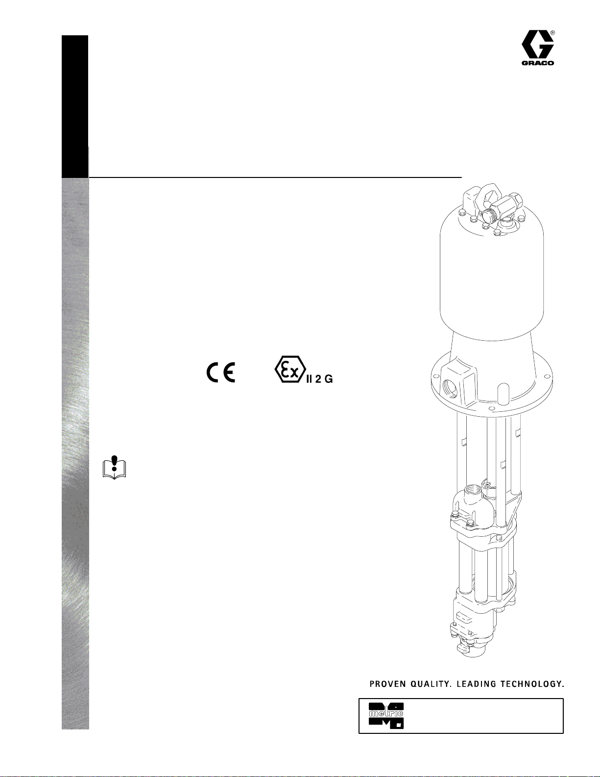
HIGH FLOR Pumps
Designed for low pressure, medium volume
circulation of finishing materials
NOTES:
Stainless steel pumps are severe-duty and
electropolished. Use with water-base coatings.
Refer to manual 307837 for adapter kits to mount
the displacement pump to an existing motor.
308793L
This manual contains and
compliant models. For a list of models with this compliancy,
see pages 5 and 6.
Patent Pending
Read warnings and instructions.
See page 2 for table of contents. See pages 5
and 6 for list of models.
Senator Pump
Shown
01921B
GRACO INC.ąP.O. BOX 1441ąMINNEAPOLIS, MNą55440-1441
Copyright 1997, Graco Inc. is registered to I.S. EN ISO 9001
Page 2
Table of Contents
Symbols 2. . . . . . . . . . . . . . . . . . . . . . . . . . . . . . . . . . . . . .
Warnings 2. . . . . . . . . . . . . . . . . . . . . . . . . . . . . . . . . . . . . .
Pump Models 5. . . . . . . . . . . . . . . . . . . . . . . . . . . . . . . . . .
Installation
All Pumps 7. . . . . . . . . . . . . . . . . . . . . . . . . . . . . . . . . .
Air-Powered Pumps 10. . . . . . . . . . . . . . . . . . . . . . . .
Hydraulic-Powered Pumps 12. . . . . . . . . . . . . . . . . . .
Operation
All Pumps 15. . . . . . . . . . . . . . . . . . . . . . . . . . . . . . . . .
Air-Powered Pumps 16. . . . . . . . . . . . . . . . . . . . . . . .
Hydraulic-Powered Pumps 17. . . . . . . . . . . . . . . . . . .
Maintenance 18. . . . . . . . . . . . . . . . . . . . . . . . . . . . . . . . . .
Troubleshooting 21. . . . . . . . . . . . . . . . . . . . . . . . . . . . . . .
Service 22. . . . . . . . . . . . . . . . . . . . . . . . . . . . . . . . . . . . . .
Parts
President Pumps 32. . . . . . . . . . . . . . . . . . . . . . . . . . .
Quiet Senator Pumps 34. . . . . . . . . . . . . . . . . . . . . . .
Quiet Bulldog Pumps 35. . . . . . . . . . . . . . . . . . . . . . .
Symbols
Viscount Pumps 36. . . . . . . . . . . . . . . . . . . . . . . . . . . .
Carbon Steel Displacement Pumps 37. . . . . . . . . . .
Electropolished Stainless Steel
Displacement Pumps 39. . . . . . . . . . . . . . . . . . . . . . .
Electropolished Stainless Steel
Displacement Pumps, with bsp threads 41. . . . . . . .
Seal and Throat Packing Kits 45. . . . . . . . . . . . . . . . . . .
Conversion Kits 45. . . . . . . . . . . . . . . . . . . . . . . . . . . . . . .
Accessories 47. . . . . . . . . . . . . . . . . . . . . . . . . . . . . . . . . .
Dimensions 47. . . . . . . . . . . . . . . . . . . . . . . . . . . . . . . . . . .
Mounting Diagrams 48. . . . . . . . . . . . . . . . . . . . . . . . . . . .
Technical Data and Performance Charts
President Pumps 50. . . . . . . . . . . . . . . . . . . . . . . . . . .
Senator Pumps 55. . . . . . . . . . . . . . . . . . . . . . . . . . . .
Bulldog Pumps 56. . . . . . . . . . . . . . . . . . . . . . . . . . . . .
Viscount Pumps 57. . . . . . . . . . . . . . . . . . . . . . . . . . . .
Warranty 60. . . . . . . . . . . . . . . . . . . . . . . . . . . . . . . . . . . . .
Graco Information 60. . . . . . . . . . . . . . . . . . . . . . . . . . . . .
Warning Symbol
WARNING
This symbol alerts you to the possibility of serious
injury or death if you do not follow the instructions.
WARNING
PRESSURIZED EQUIPMENT HAZARD
Spray from the gun/valve, hose leaks, or ruptured components can splash fluid in the eyes or on the
skin and cause serious injury.
D Do not point the gun/valve at anyone or at any part of the body.
D Do not stop or deflect leaks with your hand, body, glove or rag.
D Follow the Pressure Relief Procedure on page 15 whenever you: are instructed to relieve pres-
sure; stop spraying/dispensing; clean, check, or service the equipment; and install or clean the
spray tip/nozzle.
Caution Symbol
CAUTION
This symbol alerts you to the possibility of damage to
or destruction of equipment if you do not follow the
instructions.
D Tighten all fluid connections before operating the equipment.
D Check the hoses, tubes, and couplings daily. Replace worn, damaged, or loose parts immediately.
2 308793
Permanently coupled hoses cannot be repaired; replace the entire hose.
Page 3
INSTRUCTIONS
WARNING
EQUIPMENT MISUSE HAZARD
Equipment misuse can cause the equipment to rupture or malfunction and result in serious injury.
D This equipment is for professional use only.
D Read all instruction manuals, tags, and labels before operating the equipment.
D Use the equipment only for its intended purpose. If you are uncertain about usage, call your Graco
distributor.
D Do not alter or modify this equipment. Use only genuine Graco parts and accessories.
D Check equipment daily. Repair or replace worn or damaged parts immediately.
D Do not exceed the maximum working pressure stated on the equipment or in the Technical Data
for your equipment. Do not exceed the maximum working pressure of the lowest rated component
in your system.
D Use fluids and solvents which are compatible with the equipment wetted parts. Refer to the Tech-
nical Data section of all equipment manuals. Read the fluid and solvent manufacturer’s warnings.
D Do not use hoses to pull equipment.
D Route hoses away from traffic areas, sharp edges, moving parts, and hot surfaces. Do not expose
Graco hoses to temperatures above 82_C (180_F) or below –40_C (–40_F).
D Wear hearing protection when operating this equipment.
D Do not lift pressurized equipment.
D Comply with all applicable local, state, and national fire, electrical, and safety regulations.
MOVING PARTS HAZARD
Moving parts, such as the air motor piston, can pinch or amputate your fingers.
D Keep clear of all moving parts when starting or operating the pump.
D Before servicing the equipment, follow the Pressure Relief Procedure on page 15 to prevent the
equipment from starting unexpectedly.
308793 3
Page 4
WARNING
FIRE AND EXPLOSION HAZARD
Improper grounding, poor ventilation, open flames or sparks can cause a hazardous condition and result in a fire or explosion and serious injury.
D Ground the equipment and the object being sprayed. Refer to Grounding on page 7.
D If there is any static sparking or you feel an electric shock while using this equipment, stop spray-
ing/dispensing immediately. Do not use the equipment until you identify and correct the problem.
D Provide fresh air ventilation to avoid the buildup of flammable fumes from solvents or the fluid be-
ing sprayed/dispensed.
D Keep the spray/dispense area free of debris, including solvent, rags, and gasoline.
D Electrically disconnect all equipment in the spray/dispense area.
D Extinguish all open flames or pilot lights in the spray/dispense area.
D Do not smoke in the spray/dispense area.
D Do not turn on or off any light switch in the spray/dispense area while operating or if fumes are
present.
D Do not operate a gasoline engine in the spray/dispense area.
TOXIC FLUID HAZARD
Hazardous fluid or toxic fumes can cause serious injury or death if splashed in the eyes or on the skin,
inhaled, or swallowed.
D Know the specific hazards of the fluid you are using.
D Store hazardous fluid in an approved container. Dispose of hazardous fluid according to all local,
state and national guidelines.
D Always wear protective eyewear, gloves, clothing and respirator as recommended by the fluid and
solvent manufacturer.
4 308793
Page 5
Pump Models
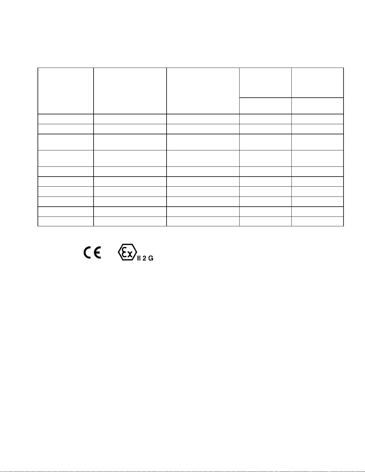
PTFE
NOTE: These pumps are not suitable for metering. Contact your Graco distributor for more information.
CARBON STEEL MODELS
Maximum Air
(or Hydraulic*)
Working
Pressure
Complete
Pump Part No.
**220560, Series B 2:1 President (32) 239834, Series A (37) 1.2, 12 (180) 2.5, 25 (360)
**220561, Series B 3:1 President (32) 239833, Series A (37) 1.1, 11 (166) 3.4, 34 (500)
**239855, Series A 3:1 President, stubby
**237223, Series B 3:1 President,
**220565, Series B 3.5:1 Quiet Senator (34) 239834, Series A (37) 0.7, 7.0 (100) 2.4, 24 (350)
**220567, Series B 2.5:1 Quiet Senator (34) 239835, Series A (37) 0.7, 7.0 (100) 1.7, 17 (250)
**220577, Series B 4:1 Quiet Bulldog (35) 239835, Series A (37) 0.7, 7.0 (100) 2.8, 28 (400)
**236601, Series B Viscount I+ (36) 239833, Series A (37) 10.3, 103 (1500)* 3.1, 31 (450)
**236605, Series B Viscount I+ (36) 239834, Series A (37) 10.3, 103 (1500)* 2.1, 21 (300)
**236712, Series B Viscount I+ (36) 239835, Series A (37) 10.3, 103 (1500)* 1.5, 15 (225)
Ratio and Type
(parts list page)
(32)
w/ packings (32)
Displacement Pump
(parts list page) MPa, bar (psi) MPa, bar (psi)
239833, Series A (37) 1.1, 11 (166) 3.4, 34 (500)
239860, Series A (37) 1.1, 11 (166) 3.4, 34 (500)
Maximum Fluid
Working
Pressure
** This model is and compliant.
308793 5
Page 6
Pump Models
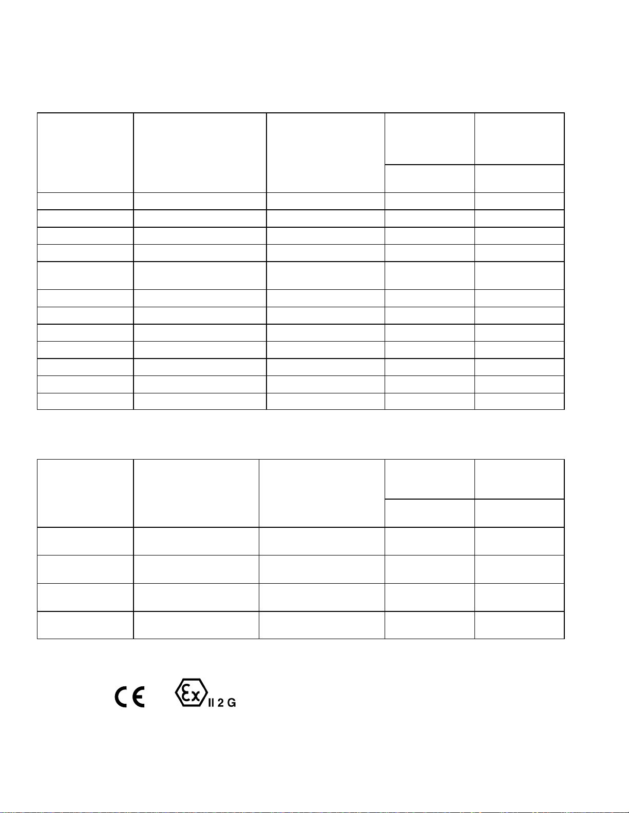
PTFE
NOTE: These pumps are not suitable for metering. Contact your Graco distributor for more information.
SEVERE-DUTY ELECTROPOLISHED STAINLESS STEEL MODELS
Maximum Air
(or Hydraulic*)
Working
Pressure
Complete
Pump Part No.
**220562, Series C 1.5:1 President (32) 239838, Series B (39) 1.2, 12 (180) 1.9, 19 (270)
**220563, Series C 2:1 President (32) 239837, Series B (39) 1.2, 12 (180) 2.5, 25 (360)
**220564, Series C 3:1 President (32) 239836, Series B (39) 1.1, 11 (166) 3.4, 34 (500)
**239854, Series B 3:1 President, stubby (32) 239836, Series B (39) 1.1, 11 (166) 3.4, 34 (500)
**237222, Series C 3:1 President,
**220568, Series C 3.5:1 Quiet Senator (34) 239837, Series B (39) 0.7, 7.0 (100) 2.4, 24 (350)
**220570, Series C 2.5:1 Quiet Senator (34) 239838, Series B (39) 0.7, 7.0 (100) 1.7, 17 (250)
**220578, Series C 4:1 Quiet Bulldog (35) 239838, Series B (39) 0.7, 7.0 (100) 2.8, 28 (400)
**236602, Series C Viscount I+ (36) 239836, Series B (39) 10.3, 103 (1500)* 3.1, 31 (450)
**236606, Series C Viscount I+ (36) 239837, Series B (39) 10.3, 103 (1500)* 2.1, 21 (300)
**236713, Series C Viscount I+ (36) 239838, Series B (39) 10.3, 103 (1500)* 1.5, 15 (225)
244142, Series A Viscount I+ (36) 239859, Series B (39) 10.3, 103 (1500)* 3.1, 31 (450)
Ratio and Type
(parts list page)
w/ packings (32)
Displacement Pump
(parts list page) MPa, bar (psi) MPa, bar (psi)
239859, Series B (39) 1.1, 11 (166) 3.4, 34 (500)
Maximum Fluid
Working
Pressure
SEVERE-DUTY ELECTROPOLISHED STAINLESS STEEL MODELS,
WITH BSP THREADS
Maximum Air
Working
Pressure
Complete
Pump Part No.
**240618, Series A 3:1 President (32) 240610, Series A, with
**240619, Series A 3:1 President (32) 240611, Series A, without
**240625, Series B 4:1 Quiet Bulldog (35) 240606, Series A, with
**240626, Series B 4:1 Quiet Bulldog (35) 240607, Series A, without
NOTE: High-Flo displacement pumps 240608 and 240612 (with tri-clamp adapters) and 240609 and 240613 (without tri-clamp adapters) are available as options. See page 43 for parts.
** This model is and compliant.
Ratio and Type
(parts list page)
Displacement Pump
(parts list page) MPa, bar (psi) MPa, bar (psi)
1.1, 11 (166) 3.4, 34 (500)
tri-clamp adapters (41)
1.1, 11 (166) 3.4, 34 (500)
tri-clamp adapters (41)
0.7, 7.0 (100) 2.8, 28 (400)
tri-clamp adapters (41)
0.7, 7.0 (100) 2.8, 28 (400)
tri-clamp adapters (41)
Maximum Fluid
Working
Pressure
6 308793
Page 7
Installation (All Pumps)
Application
The High-Flo pump is designed for low pressure,
medium volume circulation of finishing materials such
as paints and stains.
Do not use this pump for flushing or purging lines with
caustics, acids, abrasive line strippers, and other
similar fluids.
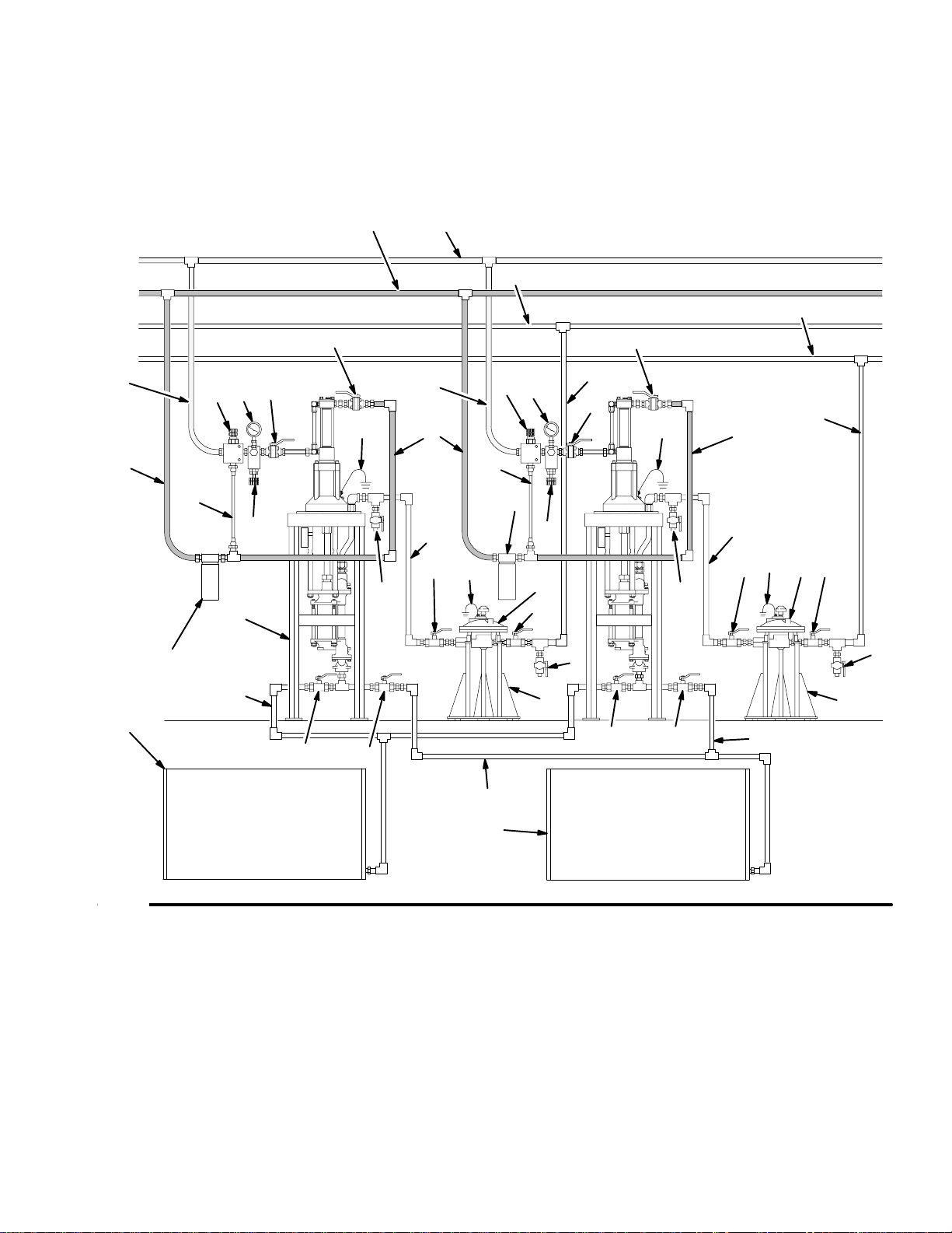
Typical Installation
The Typical Installations shown in Figs. 4 and 5, and
the following installation information are only guides.
Proper sizing of the pump, accessories and lines is
essential to get the maximum performance from your
system. Contact your Graco distributor for assistance
in designing a system to meet your needs.
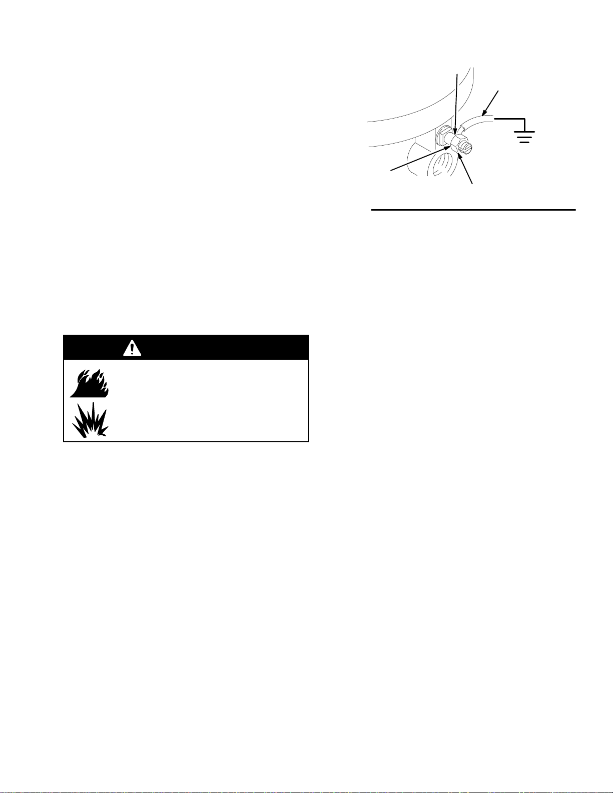
Grounding
WARNING
Z
Y
X
W
Fig. 1
2. Air and fluid hoses: use only electrically conductive
hoses.
3. Air compressor or hydraulic power supply: follow
manufacturer’s recommendations.
4. Surge tank: use a ground wire and clamp.
See Fig. 1.
5. Spray gun: ground through connection to a properly grounded fluid hose and pump.
0720
FIRE AND EXPLOSION HAZARD
Before operating the pump, ground the
system as explained below. Also read
the section FIRE AND EXPLOSION
HAZARD on page 4.
1. Pump: use the ground wire and clamp. See Fig. 1.
Loosen the grounding lug locknut (W) and washer
(X). Insert one end of a 12 ga (1.5 mm@) minimum
ground wire (Y) into the slot in lug (Z) and tighten
the locknut securely. Connect the other end of the
wire to a true earth ground. Order Part No.
237569 Ground Wire and Clamp.
6. Fluid supply container: follow your local code.
7. Object being sprayed: follow your local code.
8. Solvent pails used when flushing: follow your local
code. Use only metal pails, which are conductive,
placed on a grounded surface. Do not place the
pail on a nonconductive surface, such as paper or
cardboard, which interrupts the grounding continuity.
9. To maintain grounding continuity when flushing or
relieving pressure, hold a metal part of the spray
gun firmly to the side of a grounded metal pail,
then trigger the gun.
308793 7
Page 8
Installation (All Pumps)
Mount the Pump
This pump can be mounted on a floor stand, cart, wall
bracket, or drum. The floor stand shown in Figs. 4 and
5 is Part. No. 220581.
Instructions for mounting the pump are supplied with
the mounting accessory.
Plumbing
Most displacement pumps have a 1–1/2 in. npt(f) fluid
inlet and a 1 in. npt(f) fluid outlet. Models 240606,
240607, 240608, 240609, 240610, 240611, 240612,
and 240613, have a 1–1/2 in. bsp(f) fluid inlet and a
1–1/4 in. bsp(f) fluid outlet.
Use a minimum 25 mm (1 in.) diameter pipe or hose
between the pump outlet and any supply line accessories. Use a minimum 38 mm (1–1/2 in.) diameter pipe
or hose between the mix tanks and pump inlet.
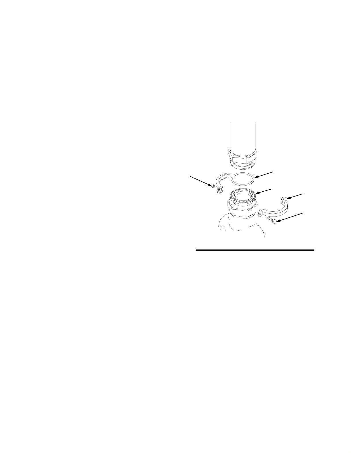
Pumps With Tri-Clamp Adapters
Displacement Pumps 240606, 240608, 240610, and
240612 include tri-clamp adapters which allow sanitary
pipe to be connected to the pump inlet and outlet.
Refer to Fig. 2.
Install a 1–1/2 in. tri-clamp gasket (GG, not supplied)
in the groove of the tri-clamp adapter (LL). Mate the
tri-clamp adapter with the sanitary pipe and secure
with two clamps (HH), bolts (JJ), and nuts (KK) (not
supplied). Install the bolts in opposite directions.
KK
GG
LL
HH
JJ
When using a stainless steel pump, use stainless steel
plumbing to maintain a corrosion-resistant system.
8689A
Fig. 2
8 308793
Page 9
Installation (All Pumps)
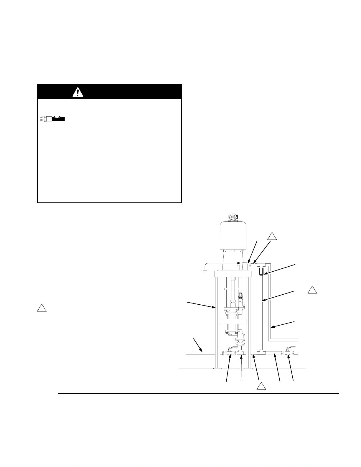
Non-Circulating Systems
In non-circulating systems with a fluid outlet that can
be closed off (causing the pump to stall), install a fluid
pressure relief valve (AA) and a return line (BB) leading back to the fluid supply line (C). See Fig. 3.
WARNING
COMPONENT RUPTURE HAZARD
The pressure relief valve reduces the
risk of the pump overpressurizing if the
piston seal is worn and leaking, and the
fluid outlet is closed off. Install the valve so the arrow on its body matches the direction of fluid flow.
Do not install a fluid shutoff valve in the fluid line
between the pump outlet (DD) and the pump inlet
(CC). Doing so defeats the purpose of the pressure
relief valve if the shutoff valve is closed, resulting in
pump overpressurization. Overpressurization can
cause the pump or components to rupture, resulting in serious injury and property damage.
Pressure Relief Valve
(for non-circulating systems)
KEY
B Pump Stand
C Fluid Supply Line; 38 mm (1–1/2 in.) minimum diameter
D Fluid Shutoff Valve
E Fluid Line; 25 mm (1 in.) minimum diameter
AA External Pressure Relief Valve
BB Fluid Return Line
CC Pump Fluid Inlet
DD Pump Fluid Outlet
Do not install a fluid shutoff valve in the fluid line
1
between the pump outlet (DD) and the pump inlet (CC).
See the WARNING above.
Fig. 3
DD
1
AA
1
BB
B
E
C
CC
CDD 1
7656A
308793 9
Page 10
Installation (Air-Powered Pumps)
Air Line to Motor
WARNING
A bleed-type master air valve (M) is required in
your system, to help reduce the risk of serious
injury including splashing fluid in the eyes or on the
skin, and injury from moving parts if you are adjusting or repairing the pump.
The bleed-type master air valve relieves air trapped
between this valve and the pump after the air is
shut off. Trapped air can cause the pump to cycle
unexpectedly. Locate the valve close to the pump.
Order Part No. 113333.
1. The air line lubricator (N) automatically lubricates
the air motor to prevent corrosion. See Fig. 4.
2. The bleed-type master air valve (M) relieves air
trapped between itself and the motor, when the
valve is closed. Install one valve close to the
pump, downstream from the air regulator. Install a
second bleed valve upstream from all other air line
accessories, to isolate the accessories for servicing.
5. The air filter (K) removes harmful dirt and moisture
from the compressed air supply.
6. The air supply line (J) must be large enough to
supply the proper volume of air to the motor.
Fluid Line from Pump
WARNING
A fluid drain valve (U) is required in your system, to
help reduce the risk of serious injury including
splashing in the eyes or on the skin if the pump
cycles unexpectedly.
Locate one valve downstream from the pump outlet
and another valve downstream from the surge tank
(G). These drain valves are used to relieve fluid
pressure in the pump and surge tank during shutdown.
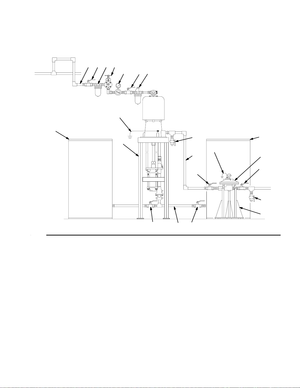
1. The surge tank (G) reduces fluid surging to prevent backflow into the pump. Mounting instructions
are supplied with the tank.
3. The air regulator (L) controls pump speed.
4. The pump runaway valve (P) shuts off the air to
the pump if the pump speed exceeds your
pre-adjusted setting. Running a pump too fast can
damage it.
2. The shutoff valves (D) before and after the surge
tank, and between each mix tank and the pump
fluid inlet, isolate these components for servicing.
3. Be sure the supply line (C) between the pump and
mix tanks (A) is level.
10 308793
Page 11
Installation (Air-Powered Pumps)
KEY
A Mix Tank
B Pump Stand
C Fluid Supply Line; 38 mm (1–1/2 in.)
minimum diameter
D Fluid Shutoff Valve
KJ
M
P
L
MN
H
A
B
E Fluid Line; 25 mm (1 in.)
minimum diameter
F Surge Tank Stand
G Surge Tank
H Ground Wire (required;
see page 7 for installation)
J Air Supply Line
K Airline Filter
L Air Regulator and Gauge
M Bleed-Type Master Air Valve (required)
N Airline Lubricator
P Pump Runaway Control Valve
U Fluid Drain Valve (required)
U
H
E
A
G
Fig. 4
D
D
U
F
D
CD
01923A
308793 11
Page 12
Installation (Hydraulic-Powered Pumps)
Hydraulic Power Supply
CAUTION
The Hydraulic Power Supply must be kept clean at
all times to avoid damage to the motor and hydraulic
power supply.
1. Blow out hydraulic lines with air and flush thoroughly before connection to the motor.
2. Plug hydraulic inlets, outlets, and line ends when
disconnecting them for any reason.
1. Be sure the power supply can provide sufficient
power to the motor.
2. Be sure the power supply is equipped with a
suction filter to the hydraulic pump.
Hydraulic Supply to Motor
Hydraulic Return from Motor
NOTE: The motor’s hydraulic outlet is 7/8 in., 37_
flare. Use a minimum 16 mm (5/8 in.) ID hydraulic
return line (K).
1. The return line shutoff valve (R) isolates the motor
when servicing the system.
CAUTION
To avoid damage to the pump, never use the return
line shutoff valve to control the hydraulic flow. Do not
install any flow control devices on the hydraulic return line.
2. The 10 micron size return filter (J) removes residue from the hydraulic fluid to help keep the system running smoothly.
Fluid Line from Pump
WARNING
NOTE: The motor’s hydraulic inlet is 3/4 in., 37_ flare.
Use a minimum 13 mm (1/2 in.) ID hydraulic supply
line (L).
1. The supply line shutoff valve (S) isolates the motor
when servicing the system. See Fig. 5.
2. The hydraulic fluid pressure gauge (Q) monitors
the hydraulic oil pressure to the motor. This helps
avoid overpressurizing the motor or displacement
pump.
3. The pressure- and temperature-compensated flow
control valve (T) prevents the motor from running
too fast, which can damage it.
4. The pressure reducing valve (P) which has a drain
line (M) running to the return line (K), controls the
hydraulic pressure to the motor.
A fluid drain valve (U) is required in your system, to
help reduce the risk of serious injury including
splashing in the eyes or on the skin if the pump
cycles unexpectedly.
Locate one valve downstream from the pump outlet
and another valve downstream from the surge tank
(G). These drain valves are used to relieve fluid
pressure in the pump and surge tank during shutdown.
1. The surge tank (G) reduces fluid surging to prevent backflow into the pump. Mounting instructions
are supplied with the tank.
2. The shutoff valves (D) before and after the surge
tank, and between each mix tank and the pump
fluid inlet, isolate these components for servicing.
3. Be sure the supply line (C) between the pump and
mix tanks (A) is level.
12 308793
Page 13
Installation (Hydraulic-Powered Pumps)
KEY
A Mix Tank
B Pump Stand
C Fluid Supply Line;
38 mm (1–1/2 in.)
minimum diameter
D Fluid Shutoff Valve
E Fluid Line; 25 mm (1 in.)
minimum diameter
F Surge Tank Stand
G Surge Tank
H Ground Wire (required; see
page 7 for installation)
KL
J 10 Micron Return Filter
K Hydraulic Return Line; 16 mm
(5/8 in.) minimum diameter
L Hydraulic Supply Line; 13 mm
(1/2 in.) minimum diameter
M Drain Line
E
P Pressure Reducing Valve
Q Hydraulic Pressure Gauge
R Return Line Shutoff Valve
S Supply Line Shutoff Valve
T Flow Control Valve
U Fluid Drain Valve (required)
E
R
L
PQ S
H
L
K
K
M
T
E
D
U
B
J
C
PQ
M
J
T
H
G
D
U
F
R
E
S
E
H
K
E
HG
D D
U
U
F
A
DD
D
D
C
Fig. 5
C
A
01924A
308793 13
Page 14

Notes
14 308793
Page 15
Operation (All Pumps)
Before You Start the Pump
Read and follow all instruction manuals, labels and
tags supplied with this pump and with all the accessories you add to the system, before operating the system.
Flush the Pump Before First Use
The pump was tested in lightweight oil. If the oil will
contaminate the fluid you are pumping, flush it out with
a compatible solvent.
Pressure Relief Procedure
WARNING
PRESSURIZED EQUIPMENT HAZARD
The system pressure must be manually relieved to
prevent the system from starting or spraying accidentally. To reduce the risk of an injury from accidental spray from the gun, splashing fluid, or
moving parts, follow the Pressure Relief Proce-
dure whenever you:
D are instructed to relieve the pressure,
D stop spraying,
D check or service any of the system equipment,
D or install or clean the spray nozzle.
1. Shut off the power to the pump.
2. In an air-powered system, close the air regulator
(L) and close the bleed-type master air valve (M).
3. In a hydraulic-powered system, close the hydraulic supply line shutoff valve (S) first, then the
return line shutoff valve (R). In a multi-pump
system, do this at each pump to isolate the pumps.
4. Close the fluid shutoff valves from the supply
tanks.
5. Trigger the gun at the last gun station to relieve
fluid pressure. Maintain firm metal-to-metal contact
between the gun and a grounded waste pail.
Repeat for all gun stations.
6. Open all drain valves (U) to relieve fluid pressure
which may be trapped in the pump or hose.
If you suspect that pressure is not fully relieved after
following the steps above, wrap a fitting near the pump
outlet with a rag, and slowly and carefully loosen the
fitting to relieve pressure. Be careful to protect your
eyes from splashing.
308793 15
Page 16
Operation (Air-Powered Pumps)
Starting and Adjusting the Pump
1. Charge the surge tank, if you are using one. See
the separate instruction manual, 307707.
2. Open all fluid shutoff valves (D).
3. Open the dispensing valve/spray gun at the last
gun station and keep it open while starting the
pump.
4. Open the bleed-type master air valves (M).
5. Adjust the air regulator (L) to the minimum pressure necessary for the pump to cycle slowly.
6. When fluid is flowing smoothly from the gun,
release the gun trigger.
7. One at a time, open any other guns in the system
to purge air from the lines.
8. Adjust the pump runaway valve (P) according to
the instructions supplied with it.
9. Adjust the lubricator (N) according to the instructions supplied with it.
NOTE: In a circulating system, the pump operates
continuously until the power supply is shut off. In a
direct supply system, the pump starts when the gun/
valve is opened, and stops when the gun/valve is
closed.
WARNING
COMPONENT RUPTURE HAZARD
To reduce the risk of overpressurizing
your system, which could cause
component rupture and serious injury,
never exceed the specified maximum air input
pressure to the pump (see Technical Data on
pages 50–56).
Shutdown
WARNING
To reduce the risk of serious injury whenever you
are instructed to relieve pressure, always follow the
Pressure Relief Procedure on page 15.
Relieve the pressure.
16 308793
Page 17
Operation (Hydraulic-Powered Pumps)
Starting and Adjusting the Pump
1. Charge the surge tank, if you are using one. See
the separate instruction manual, 307707.
2. Open all fluid shutoff valves (D).
3. Turn on the hydraulic power supply.
4. Open the flow control valve (T) all the way.
5. Open the return line shutoff valve (R) first, then
open the supply line shutoff valve (S).
6. Open the dispensing valve/spray gun at the last
gun station and keep it open while starting the
pump.
7. Adjust the pressure reducing valve (P) until you
get the desired fluid pressure.
8. When fluid is flowing smoothly from the gun,
release the gun trigger.
9. One at a time, open any other guns in the system
to purge air from the lines.
10. With a gun triggered open (dead-end systems
only) or with the pump running in a circulating
system, count the cycle rate of the pump for one
minute. Close the flow control valve (T) until the
cycle rate drops to below the desired cycle rate.
12. Release the gun trigger.
NOTE: In a circulating system, the pump operates
continuously until the power supply is shut off. In a
direct supply system, the pump starts when the gun/
valve is opened, and stops when the gun/valve is
closed.
WARNING
COMPONENT RUPTURE HAZARD
To reduce the risk of overpressurizing
your system, which could cause
component rupture and serious injury,
never exceed the specified maximum hydraulic
input pressure to the pump (see Technical Data
on pages 57–59).
Shutdown
WARNING
To reduce the risk of serious injury whenever you
are instructed to relieve pressure, always follow the
Pressure Relief Procedure on page 15.
11. Open the flow control valve (T) slowly until the
cycle rate and fluid pressure return to the desired
level. This method of setting the hydraulic controls
ensures proper pump operation and prevents
pump runaway and damage if the fluid supply runs
dry.
Relieve the pressure.
Always shut off the supply line shutoff valve (S) first,
and then the return line shutoff valve (R). This is to
prevent overpressurizing the motor or its seals.
308793 17
Page 18
Maintenance
Preventive Maintenance Schedule
The operating conditions of your particular system
determine how often maintenance is required. Establish a preventive maintenance schedule by recording
when and what kind of maintenance is needed, and
then determine a regular schedule for checking your
system. Your maintenance schedule should include the
following:
Flushing
WARNING
FIRE AND EXPLOSION HAZARD
Before flushing, read the section FIRE
AND EXPLOSION HAZARD on page
4. Be sure the entire system and flushing pails are properly grounded. Refer to
Grounding on page 7.
1. Flush before shutting down the system for an
extended period of time.
2. Flush before repairing the pump, if possible.
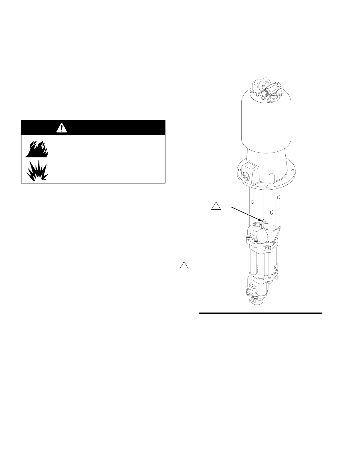
Excessive Leaking at Throat
If you see excessive leaking at the throat, and tightening the packing nut does not help, replace the throat
packings. See page 27.
Senator Pump
Shown
1
21
3. Flush before the fluid you are pumping can dry out,
settle or set up in the pump and hoses.
Packing Nut Tightness
The packing nut (21) should be tight enough to stop
leakage, but no tighter. Overtightening compresses
and damages the packings, and may cause the pump
to leak, reducing performance. See Fig. 6.
To check the adjustment of the packing nut, first relieve fluid pressure. If you have a torque wrench,
tighten the packing nut to 34–40 NSm (25–30 ft–lb).
Torque to 34–40 NSm
1
(25–30 ft–lb).
Fig. 6
01921B
18 308793
Page 19

Maintenance
Air Line Lubricator
Keep properly filled for automatic air motor lubrication.
Air Line Filter
Drain and clean as necessary.
Hydraulic Power Supply Check
Carefully follow the hydraulic power supply manufacturer’s recommendations on reservoir and filter cleaning, and periodic changes of hydraulic fluid.
Mix Tank Volume
Don’t let the mix tank run dry. When the tank is empty,
the pump demands more power as it tries to suck in
some fluid. This causes the pump to run too fast,
which can seriously damage the pump.
Stop the Pump at the Bottom of Its Stroke
WARNING
To reduce the risk of serious injury whenever you
are instructed to relieve pressure, always follow the
Pressure Relief Procedure on page 15.
Whenever you stop the pump for any reason, relieve
the pressure. Stop the pump on the downstroke,
before the air motor changes over.
CAUTION
Failure to stop the pump at the bottom of its stroke
allows fluid to dry on the piston rod, which can cause
damage to the throat packings when the pump is
restarted.
308793 19
Page 20

Notes
20 308793
Page 21

Troubleshooting
WARNING
To reduce the risk of serious injury whenever you
are instructed to relieve pressure, always follow the
Pressure Relief Procedure on page 15.
1. Relieve the pressure.
2. Check all possible problems and solutions before
disassembling pump.
PROBLEM
Pump output low on both strokes. Restricted air or hydraulic supply
Pump output low on only one
stroke.
Pump operates erratically. Exhausted fluid supply. Refill and reprime pump.
Pump will not operate. Restricted air or hydraulic supply
Pump will not prime. Suction line clogged. Clear. Flush more frequently.
Excessive throat leakage. Worn piston rod (17) or throat pack-
CAUSE SOLUTION
Clear any obstructions; be sure all shut-
lines.
Exhausted fluid supply. Refill and reprime pump.
Clogged fluid outlet line, valves, etc. Clear.
Worn piston packing (15). Replace. See page 27.
Held open or worn ball check valves. Check and repair.
Worn piston packing (15). Replace. See page 27.
Held open or worn ball check valves. Check and repair.
Worn piston packing (15). Replace. See page 27.
Excessive hydraulic fluid supply pressure to Viscount motor.
lines.
Exhausted fluid supply. Refill and reprime pump.
Clogged fluid outlet line, valves, etc. Clear.
Damaged air motor or hydraulic motor.
Fluid dried on piston rod (17). Disassemble and clean pump (see
Held open or worn ball check valves. Check and repair.
Piston assembled with wrong nut. Use only the large, round, special nut
ings.
off valves are open; increase pressure,
but do not exceed maximum working
pressure.
See Viscount motor manual.
Clear any obstructions; be sure all shutoff valves are open; increase pressure,
but do not exceed maximum working
pressure.
See motor manual.
page 27). In future, stop pump at bottom
of stroke.
(12).
Replace. See page 27.
308793 21
Page 22

Service
Disconnecting the Displacement Pump
NOTE: To change only the throat packings without
removing the displacement pump from the motor, refer
to page 25.
If you are doing a complete service of the displacement pump, disconnect it from the motor as described
in the applicable procedure on this page, and disassemble the pump as described on page 27.
NOTE: In stand or wall-mounted installations, you do
not have to remove the entire pump from its mounting.
WARNING
To reduce the risk of serious injury whenever you
are instructed to relieve pressure, always follow the
Pressure Relief Procedure on page 15.
1. Relieve the pressure.
Senator Pump Shown
G
F
H
Torque to 102–109 NSm
1
(75–80 ft-lb).
Torque to 68–75 NSm
2
(50–55 ft-lb).
E
J
1
A
C
3
2
B
D
2. Disconnect the hoses from the displacement pump
and plug the ends to prevent fluid contamination.
3. Disconnect the displacement pump from the motor
as follows:
D For Senator and Bulldog pumps (Fig. 7):
Unscrew the coupling nut (A). Unscrew the
locknuts (B) from the tie rods (C). Pull the
displacement pump (D) off the motor (E).
Remove the pin (F) and screw the coupling
(G) off the piston rod (H).
D For President (Fig. 8) and Viscount (Fig. 9)
pumps: Unscrew the coupling nut (K) from the
piston rod (H). Unscrew the locknuts (B) from
the tie rods (C). Pull the displacement pump
(D) off the motor (E).
Lubricate threads.
3
01926B
Fig. 7
Reconnecting the Displacement Pump
1. Reconnect the displacement pump to the motor as
follows:
D For Senator and Bulldog pumps (Fig. 7):
Make sure the coupling nut (A) and o-ring (J)
are in place on the coupling (G). Screw the
coupling onto the piston rod (H) and install the
pin (F). Orient the displacement pump (D) to
the motor (E) as shown. Position the displacement pump (D) on the tie rods (C). Lubricate
the threads of the tie rods. Screw the locknuts
(B) onto the tie rods loosely. Screw the coupling nut (A) onto the motor shaft and torque to
102–109 NSm (75–80 ft-lb). Torque the tie rod
locknuts to 68–75 NSm (50–55 ft-lb).
22 308793
Page 23

Service
D For President (Fig. 8) and Viscount (Fig. 9)
pumps:
NOTE: If the coupling rod (G) and tie rods (C)
have been disassembled from a President or
Viscount motor, refer to Reassembling the
Coupling Rod and Tie Rods. If they have not
been removed, proceed as follows:
Orient the displacement pump (D) to the motor
(E) and adapter plate (L) as shown. Position
the displacement pump (D) on the tie rods (C).
Lubricate the threads of the tie rods. Screw the
locknuts (B) onto the tie rods loosely. Screw
the coupling nut (K) onto the piston rod (H)
and torque to 102–109 NSm (75–80 ft-lb).
Torque the tie rod locknuts to 68–75 NSm
(50–55 ft-lb).
2. Flush and test the pump before reinstalling it in the
system. Connect hoses for flushing. Flush the
pump. While it is pressurized, check for smooth
operation and leaks. Adjust or repair as necessary
before reinstalling in the system. Reconnect the
pump ground wire before operating.
President Pump Shown
Viscount I+ Pump Shown
E
L
C
3
B
2
Torque to 102–109 NSm
1
(75–80 ft-lb).
Torque to 68–75 NSm
2
(50–55 ft-lb).
3
Lubricate threads.
Fig. 9
G
1
K
H
D
01928B
Torque to 102–109 NSm
1
(75–80 ft-lb).
Torque to 68–75 NSm
2
(50–55 ft-lb).
3
Lubricate threads.
Fig. 8
E
L
K
1
C
H
3
B
2
D
01927B
308793 23
Page 24

Service
Reassembling the Coupling Rod and Tie
Rods (President and Viscount only)
NOTE: Use this procedure only if the coupling rod (G)
and tie rods (C) have been disassembled from a
President or Viscount motor, to ensure proper alignment of the motor shaft to the piston rod.
1. Loosen, but do not remove, the screws (M) holding
the adapter plate (L) to the motor (E). See Fig. 10.
2. Screw the tie rods (C) into the adapter plate (L)
and torque to 68–75 NSm (50–55 ft-lb).
On Viscount I+ pumps, the tie rods will engage
threaded holes in the base of the motor.
3. Fill the cavity in the bottom of the motor shaft with
grease. Screw the coupling (G) into the motor
shaft until the pin holes align. Install the pin (F) in
the second hole from the end of the coupling for
President pumps, and in the first hole from the
end of the coupling for Viscount pumps.
4. Align the displacement pump with the tie rods (C)
and loosely install the locknuts (B).
5. Screw the coupling nut (K) onto the piston rod (H)
and torque to 102–109 NSm (75–80 ft-lb).
6. Torque the screws (M) holding the adapter plate
(L) to the motor (E) to 20–23 NSm (15–17 ft-lb).
Torque the tie rod locknuts (B) to 68–75 NSm
(50–55 ft-lb).
President Pump Shown
4
F
G
K
1
H
Torque to 102–109 NSm
1
(75–80 ft-lb).
Torque to 68–75 NSm
2
(50–55 ft-lb).
Torque to 20–23 NSm
3
(15–17 ft-lb).
For President Pumps,
4
install in second hole
from end of coupling (G);
for Viscount Pumps,
use first hole.
5
Lubricate threads.
Fig. 10
C
5
01929B
E
M
3
L
2
B
2
24 308793
Page 25

Service
PTFE
PTFE
Replacing the Throat Packings Without
Disconnecting the Displacement Pump
NOTE: To replace the throat packings as part of a
complete servicing of the displacement pump, refer to
page 27.
NOTE: Throat packing kits are available. Refer to page
45 to order. Parts supplied in the throat packing kit are
marked with a symbol, for example (19{). For the best
results, use all the parts in the kit.
1. Flush the pump, if possible.
2. Stop the pump at the middle of its stroke.
3. Shut off the air or hydraulic supply.
4. Remove the cotter pin (F). See Fig. 7 for Senator
and Bulldog Pumps, and Fig. 10 for President and
Viscount Pumps.
5. Cycle the pump slowly to the bottom of its stroke.
WARNING
NOTE: To convert carbon steel pumps to the throat
cartridge design used on stainless steel pumps, order
Conversion Kit 239869.
10. Remove the glands (19, 26) and packings (20, 25).
11. Lubricate the throat packings and glands. Install
one male gland (19{), then five v-packings with the
lips facing down: one UHMWPE (20{), one leather
(25{), UHMWPE, leather, UHMWPE. Install the
female gland (26{). Install three v-packings with
the lips facing up: UHMWPE, leather, UHMWPE.
Install the other male gland (19{). Install the
packing nut (21) finger-tight.
NOTE: Model 239859, 239860, 240612, and 240613
displacement pumps use 8 v-packings (20) in
the throat, instead of 5 UHMWPE (20) and 3 leather
(25) as on all other models.
12. Stainless Steel Pumps Only: Install the o-ring
(39{) on the throat cartridge (38), then screw the
throat cartridge into the upper pump housing (1).
Torque the throat cartridge to 135 NSm (100 ft-lb).
To reduce the risk of serious injury whenever you
are instructed to relieve pressure, always follow the
Pressure Relief Procedure on page 15.
6. Relieve the pressure.
7. Uncouple the displacement pump as follows:
D Senator and Bulldog Pumps: See Fig. 7.
Unscrew the coupling nut (A) from the motor
shaft. Unscrew the coupling (G) from the
piston rod (H). Set the coupling and coupling
nut aside.
D President and Viscount Pumps: See Figs. 9
and 10. Unscrew the coupling nut (K) from the
piston rod (H). Unscrew the coupling rod (G)
from the air motor and set it aside.
8. See Fig. 11. Loosen and remove the packing nut
(21).
9. Stainless Steel Pumps Only: Loosen and remove
the throat cartridge (38). Remove the r
o-ring (39).
13. Torque the packing nut (21) to 34–40 NSm (25–30
ft-lb).
14. Recouple the displacement pump as follows:
D Senator and Bulldog Pumps: See Fig. 7. Make
sure the coupling nut (A) and o-ring (J) are in
place on the coupling (G). Screw the coupling
onto the piston rod (H). Screw the coupling nut
(A) onto the motor shaft and torque to
102–109 NSm (75–80 ft-lb).
D President and Viscount Pumps: See Fig. 10.
Screw the coupling (G) into the motor shaft
until the pin holes align. Screw the coupling
nut (K) onto the piston rod (H) and torque to
102–109 NSm (75–80 ft-lb).
15. Reinstall the pin (F). If necessary, reconnect the
air or hydraulic supply and move the pump to the
middle of its stroke. Install the pin (F) in the sec-
ond hole from the end of the coupling for President pumps, and in the first hole from the end of
the coupling for Viscount pumps.
308793 25
Page 26

Service
PTFE
Throat Packing Detail
OUTLET
17
21
5
7
21 (Ref)
5
19{
20{
14
25{
20{
26{
20{
25{
20{
25{
20{
14
14
1
12 13
1
1
1
1
151516
38
1
19{
39{
38 (Ref)
39{ (Ref)
151516
01930C
1
Lips of v-packings must face down.
5
Torque to 34–40 NSm (25–30 ft-lb).
7
Apply sealant to threads.
Lubricate.
12
Models 239859, 239860, 240612, and
13
240613 use 8 v-packings (20),
instead of 5 UHMWPE (20) and 3 leather
(25) as shown for all other models.
Lips of v-packings must face up.
14
Used on stainless steel pumps only.
15
16
Torque to 135 NSm (100 ft-lb).
Fig. 11
7522B
26 308793
Page 27

Service
PTFE
Repair Kits
Pump seal kits are available for each pump size.
Throat packing kits are also available. Refer to page
45 to order.
Parts supplied in the pump seal kit are marked with
one asterisk in the text and drawings, for example (2*).
Parts supplied in the throat packing kit are marked with
a symbol, for example (19{). For the best results, use
all the parts in the kit.
Disassembling the Displacement Pump
1. Remove the pump from the motor as explained on
page 22.
2. Secure the displacement pump intake housing (10)
in a vise.
3. Refer to Fig. 13. Loosen but do not remove the
packing nut (21) and the cartridge (38, used on
stainless steel pumps only).
4. Remove the four capscrews (9) and washers (8)
from around the pump outlet housing (22).
5. Remove the outlet housing (22), balls (23), seats
(24) and gaskets (7).
NOTE: One intake seat (6) includes a pressure relief
valve (V). This seat must be located exactly where
shown (the left side as viewed in Fig. 13).
12. Remove the balls (5), intake seats (6 and 34), and
gaskets (7).
13. Inspect the pressure relief valve in the seat (6) to
make sure it is not clogged. Press down on the
valve’s ball (B) to see if the ball and the spring (S)
are free to move. See Fig. 12.
CAUTION
If the pressure relief valve in the seat (6) is clogged
or filled with material, soak the seat in a compatible
solvent. Make sure all material residue is cleaned
from the ball and seat area.
If the relief valve cannot be thoroughly cleaned so
that the ball and spring are free to move, replace the
seat (6).
14. Place the flats of the piston nut (12) in a vise.
Unscrew the rod (17) from the nut. Disassemble
the piston (16) and remove the seal (15).
6. Remove the three tie bolts (13) and lockwashers
(14). Lift off the upper pump housing (1), along
with the fluid tubes (3), cylinder (4), and piston
assembly (16).
7. Remove the packing nut (21). On stainless steel
pumps only, remove the throat cartridge (38) and
o-ring (39).
8. Remove the glands (19, 26) and packings (20, 25).
NOTE: Model 239859, 239860, 240612, and 240613
displacement pumps use 8 v-packings (20) in
the throat, instead of 5 UHMWPE (20) and 3 leather
(25) as on all other models.
9. Remove the tubes (3) and cylinder (4) from the
housing (1). Pull the piston assembly out of the
cylinder.
10. Remove the intake housing (10) from the vise.
11. Remove the four capscrews (9) and washers (8)
from the intake housing (10). Use a flatblade
screwdriver inserted between the lower pump
housing (11) and the intake housing (10) to separate them.
11
6
B
S
10
7523B
Fig. 12
Cleaning and Inspecting Parts
Clean all parts in a compatible solvent. Inspect all
parts for wear or damage. If you are using a repair kit,
use all the new parts in the kit, discarding the old ones
they replace. Replace any other parts as needed.
Worn or damaged parts may cause the pump to perform poorly or cause premature wear of the new seals
and packings.
308793 27
Page 28

Service
PTFE
Severe-Duty Electropolished Stainless Steel Pump Shown
21
4
19
20
25
20
26
22
23
20
25
OUTLET
9
20
25
20
8
19
38
39
1
5
5
Models 239859, 239860, 240612, and 240613 use 8
1
2
3
4
5
v-packings (20), instead of 5 UHMWPE (20) and 3
leather (25) as shown for all other models.
Relief valve intake seat.
Intake seat without a relief valve.
Torque to 34–40 NSm (25–30 ft-lb).
Used on stainless steel pumps only.
17 (Ref)
16
15
16
24
12
7
2
18
1
11
14
Y35
3
4
2
7
5
V
6
2
7
5
34
3
18
13
8
Fig. 13
28 308793
17
9
10
INLET
01930C
Page 29

Service
PTFE
Reassembling the Displacement Pump
NOTE: When thread sealant is specified, use low
strength (blue) Loctiter.
1. Place the halves of the piston (16) around the
packing (15*) and snap them together. See Fig.
15.
2. Apply thread sealant to the piston rod (17) threads.
Screw the rod through the piston and packings and
into the special piston nut (12). Torque the nut to
68–81 NSm (50–60 ft-lb).
3. With the lower pump housing (11) turned upside
down, install the balls (5) and the gaskets (7*).
WARNING
COMPONENT RUPTURE HAZARD
The relief valve seat (6) must be installed at the fluid intake, as shown in
Fig. 15. The relief valve relieves pressure trapped in the pump cylinder when the pump
is shut off, and reduces the risk of pump overpressurization. The seat cannot relieve pressure if
installed in any other position.
6. Place the intake housing (10) on the lower pump
housing (11). Install the lockwashers (8) and
capscrews (9). Torque to 34–40 NSm (25–30 ft-lb).
See Fig. 15.
7. Place the intake housing (10) in a vise. Place one
o-ring (2*) in each side of the lower pump housing
(11), where the tubes (3) sit. Place o-rings (2*) in
the grooves at each end of the tubes. Place a
gasket (18*) in both the upper and lower housings
(1 and 11). Position the tubes and cylinder (4) in
the lower housing (11).
8. Lubricate the inside of the cylinder (4). Slide the
piston assembly into the cylinder.
9. On stainless steel pumps, install the o-ring (39{)
on the throat cartridge (38), then screw the throat
cartridge into the upper pump housing (1).
10. Lubricate the throat packings and glands. Install
one male gland (19{), then five v-packings with the
lips facing down: one UHMWPE (20{), one leather
(25{), UHMWPE, leather, UHMWPE. Install the
female gland (26{). Install three v-packings with
the lips facing up: UHMWPE, leather, UHMWPE.
Install the other male gland (19{). Install the
packing nut (21) finger-tight.
4. Install the relief valve intake seat (6) in the left side
of the lower housing (11), as viewed in Fig. 15 (the
arrow on label 35 points to the correct location).
The pin (P) on the seat must point up into the
housing. The pin limits the positioning of the seat,
ensuring that the vent hole (V) is not blocked by
part of the housing. Refer to Fig. 14.
5. Install the intake seat without a relief valve (34) in
the right side of the lower housing (11).
NOTE: The seats (6 and 34) are not reversible; the
chamfered side must face the ball.
11
6
P
10
V
7*
NOTE: Model 239859, 239860, 240612, and 240613
displacement pumps use 8 v-packings (20) in
the throat, instead of 5 UHMWPE (20) and 3 leather
(25) as on all other models.
11. Install the upper pump housing (1). It may not seat
well on the tubes and cylinder. Install the bolts and
lockwashers (14) from the lower pump housing
(11). As you tighten the bolts into the upper housing (1), they will draw the housings firmly onto the
tubes and cylinders. Tighten the bolts uniformly
and torque to 34–40 NSm (25–30 ft-lb).
12. On stainless steel pumps, torque the cartridge
(38) to 135 NSm (100 ft-lb).
13. Torque the packing nut (21) to 34–40 NSm (25–30
ft-lb).
14. Place a ball (23), seat (24) and gasket (7*) in each
side of the outlet housing (22). Install the outlet
housing on the upper pump housing (1). Note that
the flatter side of the housing faces the outside
edge of the pump. Install the lockwashers (8) and
screws (9), and torque to 34–40 NSm (25–30 ft-lb).
Fig. 14
7523B
15. Reconnect the displacement pump to the motor as
explained on page 22.
308793 29
Page 30

Side View of Outlet Housing (22)
PTFE
Service
Throat Packing Detail
9
01932
10
17
7
21 (Ref)
5
19{
20{
14
OUTLET
21
5
151516
38
1
22
8
23
24
9
5
8
25{
20{
26{
20{
25{
20{
25{
20{
14
14
1
12 13
1
1
1
1
19{
*7
39{
38 (Ref)
39{ (Ref)
151516
01930C
18*
13
4 5
*2
11
4
3
10
Fig. 15
6
Y35
5
*15
2
16
16
12
*2
11
1
Lips of v-packings must face down.
2
Relief valve intake seat must be installed on
the left side of the housing (11), as shown.
Orient the seat as shown in Fig. 14.
Intake seat without relief valve. Do not
3
install the relief valve seat (6) on this
side of the housing (11).
4
Tighten uniformly.
5
Torque to 34–40 NSm (25–30 ft-lb).
6
Torque to 68–81 NSm (50–60 ft-lb).
7
Apply sealant to threads.
5
5
6
18*
8
34
3
10
7*
9
10
*7
INLET
8
Left side.
9
Outside.
10
Chamfered side must face ball (5).
11
Lubricate inside diameter.
Lubricate.
12
Models 239859, 239860, 240612, and
13
240613 use 8 v-packings (20),
instead of 5 UHMWPE (20) and 3 leather
(25) as shown for all other models.
Lips of v-packings must face up.
14
Used on stainless steel pumps only.
15
16
Torque to 135 NSm (100 ft-lb).
7522B
30 308793
Page 31

Notes
308793 31
Page 32

Parts (President Pumps)
CARBON STEEL PUMPS
Model 220560, Series B, 2:1 Ratio
Model 220561, Series B, 3:1 Ratio
Model 237223, Series B, 3:1 Ratio
Model 239855, Series A, 3:1 Ratio, stubby
Ref Part
No. No. Description Qty
101 205038 MOTOR, President; see 306982 1
102 183033 ROD, tie; 13.625” (346 mm)
between shoulders 3
192582 ROD, tie; 7.625” (194 mm)
between shoulders;
used on Model 239855 only 3
103 100103 PIN, cotter; 1/8” dia x 1–1/2” 1
104 156082 PACKING, o-ring; buna-N 1
105 220883 COUPLING 1
239848 COUPLING;
used on Model 239855 only 1
106 100450 CAPSCREW, hex hd; 5/16–18
unc–2a x 1” long 3
107 239834 DISPLACEMENT PUMP
for Model 220560; see page 37 1
239833 DISPLACEMENT PUMP
for Models 220561 and 239855;
see page 37 1
239860 DISPLACEMENT PUMP
for Model 237223; see page 37 1
108 108527 NUT, lock, hex; 9/16–12 unc 3
113 100214 LOCKWASHER; 0.318” 3
114 186071 PLATE, adapter 1
115 183351 LABEL, ID (not shown) 1
SEVERE-DUTY, ELECTROPOLISHED
STAINLESS STEEL PUMPS
Model 220562, Series C, 1.5:1 Ratio
Model 220563, Series C, 2:1 Ratio
Model 220564, Series C, 3:1 Ratio
Model 237222, Series C, 3:1 Ratio
Model 239854, Series B, 3:1 Ratio, stubby
Model 240618, Series A, 3:1 Ratio, with bsp
threads and tri-clamp adapters
Model 240619, Series A, 3:1 Ratio, with bsp
threads, without tri-clamp adapters
Ref Part
No. No. Description Qty
101 205038 MOTOR, President; see 306982 1
102 183089 ROD, tie; 13.625” (346 mm)
between shoulders 3
192582 ROD, tie; 7.625” (194 mm)
between shoulders;
used on Model 239854 only 3
103 101946 PIN, cotter; 1/8” dia x 1–1/2” 1
104 156082 PACKING, o-ring; buna-N 1
105 220883 COUPLING 1
239848 COUPLING;
used on Model 239854 only 1
106 100450 CAPSCREW, hex hd; 5/16–18
unc–2a x 1” long 3
107 239838 DISPLACEMENT PUMP
for Model 220562; see page 39 1
239837 DISPLACEMENT PUMP
for Model 220563; see page 39 1
239836 DISPLACEMENT PUMP
for Models 220564 and 239854;
see page 39 1
239859 DISPLACEMENT PUMP
for Model 237222; see page 39 1
240610 DISPLACEMENT PUMP, with
tri-clamp adapters, for Model 240618;
see page 41 1
240611 DISPLACEMENT PUMP, without
tri-clamp adapters, for Model 240619;
see page 41 1
108 108683 NUT, lock, hex; 9/16–12 unc 3
113 100214 LOCKWASHER; 0.318” 3
114 186071 PLATE, adapter 1
115 183351 LABEL, ID (not shown) 1
32 308793
Page 33

Parts (President Pumps)
CARBON STEEL PUMPS
Model 220560, Series B, 2:1 Ratio
Model 220561, Series B, 3:1 Ratio
Model 237223, Series B, 3:1 Ratio
Model 239855, Series A, 3:1 Ratio, stubby
SEVERE-DUTY, ELECTROPOLISHED
STAINLESS STEEL PUMPS
Model 220562, Series C, 1.5:1 Ratio
Model 220563, Series C, 2:1 Ratio
101
106
113
Model 220564, Series C, 3:1 Ratio
Model 237222, Series C, 3:1 Ratio
Model 239854, Series B, 3:1 Ratio, stubby
Model 240618, Series A, 3:1 Ratio, with bsp
threads and tri-clamp adapters
Model 240619, Series A, 3:1 Ratio, with bsp
threads, without tri-clamp adapters
104
103
105
107
114
102
108
01929B
308793 33
Page 34

Parts (Quiet Senator Pumps)
CARBON STEEL PUMPS
Model 220565, Series B, 3.5:1 Ratio
Model 220567, Series B, 2.5:1 Ratio
Ref Part
No. No. Description Qty
101 220571 MOTOR, Quiet Senator
See 307592 for parts 1
102 183033 ROD, tie; 13.625” (346 mm)
between shoulders 3
103 100103 PIN, cotter; 1/8” dia x 1–1/2” 1
104 108284 PACKING, o-ring; buna-N 1
105 183041 COUPLING 1
106 183042 NUT, coupling 1
107 239834 DISPLACEMENT PUMP
Used on Model 220565
See separate parts list on page 37 1
239835 DISPLACEMENT PUMP
Used on Model 220567
See separate parts list on page 37 1
108 108527 NUT, lock, hex; 9/16–12 unc 3
113 181096 LABEL, ID (not shown) 1
101
SEVERE-DUTY, ELECTROPOLISHED
STAINLESS STEEL PUMPS
Model 220568, Series C, 3.5:1 Ratio
Model 220570, Series C, 2.5:1 Ratio
Ref Part
No. No. Description Qty
101 220571 MOTOR, Quiet Senator
See 307592 for parts 1
102 183089 ROD, tie; 13.625” (346 mm)
between shoulders 3
103 101946 PIN, cotter; 1/8” dia x 1–1/2” 1
104 108284 PACKING, o-ring; buna-N 1
105 183084 COUPLING 1
106 183079 NUT, coupling 1
107 239837 DISPLACEMENT PUMP
Used on Model 220568
See separate parts list on page 39 1
239838 DISPLACEMENT PUMP
Used on Model 220570
See separate parts list on page 39 1
108 108683 NUT, lock, hex; 9/16–12 unc 3
113 181096 LABEL, ID (not shown) 1
105
102
103
104
106
107
108
34 308793
01926B
Page 35

Parts (Quiet Bulldog Pumps)
CARBON STEEL PUMPS
Model 220577, Series B, 4:1 Ratio
Ref Part
No. No. Description Qty
101 215255 MOTOR, Quiet Bulldog
See 307304 for parts 1
102 183033 ROD, tie; 13.625” (346 mm)
between shoulders 3
103 100103 PIN, cotter; 1/8” dia x 1–1/2” 1
104 108284 PACKING, o-ring; buna-N 1
105 183041 COUPLING 1
106 183042 NUT, coupling 1
107 239835 DISPLACEMENT PUMP,
for Model 220577;
See separate parts list on page 37 1
108 108527 NUT, lock, hex; 9/16–12 unc 3
113 181096 LABEL, ID (not shown) 1
SEVERE-DUTY, ELECTROPOLISHED
STAINLESS STEEL PUMPS
Model 220578, Series C , 4:1 Ratio
Model 240625, Series A, 4:1 Ratio, with bsp
threads and tri-clamp adapters
Model 240626, Series A, 4:1 Ratio, with bsp
threads, without tri-clamp adapters
113 181096 LABEL, ID (not shown) 1
101
105
103
102
104
Ref Part
No. No. Description Qty
101 215255 MOTOR, Quiet Bulldog (used on
220578) See 307304 for parts 1
233077 MOTOR, Quiet Bulldog (used on
240625 and 240626)
See 307304 for parts 1
102 183089 ROD, tie; 13.625” (346 mm)
between shoulders 3
103 101946 PIN, cotter; 1/8” dia x 1–1/2” 1
104 108284 PACKING, o-ring; buna-N 1
105 183084 COUPLING 1
106 183079 NUT, coupling 1
107 239838 DISPLACEMENT PUMP,
for Model 220578;
See separate parts list on page 39 1
240606 DISPLACEMENT PUMP, with
tri-clamp adapters, for Model 240625;
See separate parts list on page 41 1
240607 DISPLACEMENT PUMP, without
tri-clamp adapters, for Model 240626;
See separate parts list on page 41 1
108 108683 NUT, lock, hex; 9/16–12 unc 3
106
107
108
01934B
308793 35
Page 36

Parts (Viscount I+ Pumps)
CARBON STEEL PUMPS
Model 236601, Series B, Model 236605, Series B, Model 236712, Series B
Ref Part
No. No. Description Qty
101 236417 MOTOR, hydraulic, Viscount I+
See 308330 for parts 1
102 183033 ROD, tie; 13.625” (346 mm)
between shoulders 3
103 100103 PIN, cotter; 1/8” dia x 1–1/2” 1
104 156082 PACKING, o-ring; buna-N 1
105 220883 COUPLING 1
107 239834 DISPLACEMENT PUMP
Used on Model 236605
See separate parts list on page 37 1
239833 DISPLACEMENT PUMP
Used on Model 236601
See separate parts list on page 37 1
239835 DISPLACEMENT PUMP
Used on Model 236712
See separate parts list on page 37 1
108 108527 NUT, lock, hex; 9/16–12 unc 3
112 100001 SCREW, cap, hex hd;
5/16–18 unc–2a x 0.625 in. (16 mm) 4
113 100214 LOCKWASHER; 0.318” 4
114 189206 PLATE, adapter 1
101
113
112
114
SEVERE-DUTY, ELECTROPOLISHED
STAINLESS STEEL PUMPS
Model 236602, Series C, Model 236606, Series C
Model 236713, Series C, Model 244142, Series A
Ref Part
No. No. Description Qty
101 236417 MOTOR, hydraulic, Viscount I+
See 308330 for parts 1
102 183089 ROD, tie; 13.625” (346 mm)
between shoulders 3
103 101946 PIN, cotter; 1/8” dia x 1–1/2” 1
104 156082 PACKING, o-ring; buna-N 1
105 220883 COUPLING 1
107 239837 DISPLACEMENT PUMP
Used on Model 236606
See separate parts list on page 39 1
239836 DISPLACEMENT PUMP
Used on Model 236602
See separate parts list on page 39 1
239838 DISPLACEMENT PUMP
Used on Model 236713
See separate parts list on page 39 1
239859 DISPLACEMENT PUMP
Used on 244142
See seperate parts list on page 39 1
108 108683 NUT, lock, hex; 9/16–12 unc 3
112 100001 SCREW, cap, hex hd;
5/16–18 unc–2a x 0.625 in. (16 mm) 4
113 100214 LOCKWASHER; 0.318” 4
114 189206 PLATE, adapter 1
102
101
(Ref)
101 (Ref)
108
104
103
105
107
36 308793
03248B
Page 37

Displacement Pump Parts
Ref
PTFE
PTFE
PTFE
CARBON STEEL DISPLACEMENT PUMPS
Model 239833, Series A; for Pump Models 220561, 236601, and 239855
Model 239834, Series A; for Pump Models 220560, 220565, and 236605
Model 239835, Series A; for Pump Models 220567, 220577, and 236712
Model 239860, Series A; for Pump Model 237223
NOTE: Part numbers vary by pump. To find the part number used in your pump, read down the chart to find the
desired ref. no., then read left to right to find the part number for your pump.
.
No. Description
1 HOUSING, pump, upper; ductile iron 192751 192751 192751 192751 1
2* PACKING, o-ring; r 108526 108526 108526 108526 6
3 TUBE, fluid; sst 183085 183085 183085 183085 2
4 CYLINDER, pump; cst 181899 183032 181900 181899 1
5 BALL, intake; 1.25” diameter; sst 101968 101968 101968 101968 2
6 SEAT, intake valve, with relief valve; sst 239805 239805 239805 239805 1
7* GASKET, seat, valve; UHMWPE 181877 181877 181877 181877 4
8 WASHER, flat; 8.4 mm; sst 111003 111003 111003 111003 8
9 CAPSCREW, hex hd; M8 x 1.25 x 25; cst 107558 107558 107558 107558 8
10 HOUSING, intake; ductile iron 192260 192260 192260 192260 1
11 HOUSING, pump, lower; ductile iron 181730 181730 181730 181730 1
12 NUT, piston; sst 108528 108528 108528 108528 1
13 CAPSCREW, hex hd; 9/16–12 unc x 7.75” long; cst 108524 108524 108524 108524 3
14 LOCKWASHER, spring; 9/16”; cst 101333 101333 101333 101333 3
15* PACKING, piston; UHMWPE 181680 183039 181793 1
PACKING, piston; 187761 1
16 PISTON; cst 181685 183040 181792 181685 2
17 ROD, piston; sst 181898 181898 181898 181898 1
18* GASKET, cylinder; UHMWPE 181875 183094 181876 181875 2
19{ GLAND, male; sst 192263 192263 192263 192263 2
20{ V-PACKING, throat; UHMWPE 183295 183295 183295 5
V-PACKING, throat; 183352 8
21 NUT, packing; sst 181684 181684 181684 181684 1
22 HOUSING, outlet; ductile iron 181728 181728 181728 181728 1
23 BALL, outlet; 1” (25 mm) diameter; sst 110259 110259 110259 110259 2
24 SEAT, valve; sst 183095 183095 183095 183095 2
25{ V-PACKING, throat; leather 183294 183294 183294 3
26{ GLAND, female; sst 192264 192264 192264 192264 1
34 SEAT, intake valve; sst 239865 239865 239865 239865 1
35Y PLATE, warning 290537 290537 290537 290537 1
36 SCREW, drive, type U; 3/16” long 100508 100508 100508 100508 2
37Y TAG, warning (not shown) 172479 172479 172479 172479 1
239833 239834 239835 239860
Displacement Pump Part Numbers
Qty
* These parts are included in the Seal Repair Kit, which may be purchased separately. Refer to page 45.
{ These parts are included in the Throat Packing Repair Kit, which may be purchased separately. Refer to page 45.
Y Replacement Danger and Warning labels, tags and cards are available at no cost.
308793 37
Page 38

Displacement Pump Parts
PTFE
CARBON STEEL DISPLACEMENT PUMPS
Model 239833, Series A; for Pump Models 220561, 236601, and 239855
Model 239834, Series A; for Pump Models 220560, 220565, and 236605
Model 239835, Series A; for Pump Models 220567, 220577, and 236712
Model 239860, Series A; for Pump Model 237223
NOTE: See Service Section for important assembly procedures, torque notes, and sealants.
22
23
24
*7
21
19{
20{
25{
9
8
*2
20{
26{
20{
25{
20{
25{
20{
19{
1
18*
Model 239860 uses 8 v-packings (20), instead of 5
4
UHMWPE (20) and 3 leather (25) as shown for all other models.
17 (Ref)
4
16
15*
16
12
38 308793
*2
11
10
14
7*
5
34
13
01936B
3
Y35, 36
4
*7
18*
17
5
6
8
9
Page 39

Displacement Pump Parts
Ref
PTFE
PTFE
PTFE
PTFE
SEVERE-DUTY ELECTROPOLISHED STAINLESS STEEL DISPLACEMENT PUMPS
Model 239836, Series B; for Pump Models 220564, 236602, and 239854
Model 239837, Series B; for Pump Models 220563, 220568, and 236606
Model 239838, Series B; for Pump Models 220562, 220570, 220578, and 236713
Model 239859, Series B; for Pump Model 237222, 244142
NOTE: Part numbers vary by pump. To find the part number used in your pump, read down the chart to find the
desired ref. no., then read left to right to find the part number for your pump.
.
No. Description
1 HOUSING, pump, upper; sst 192512 192512 192512 192512 1
2* PACKING, o-ring; r 108526 108526 108526 108526 6
3 TUBE, fluid; sst 183085 183085 183085 183085 2
4 CYLINDER, pump; sst 183049 183047 183048 183049 1
5 BALL, intake; 1.25” diameter; sst 101968 101968 101968 101968 2
6 SEAT, intake valve, with relief valve; sst 239805 239805 239805 239805 1
7* GASKET, seat, valve; UHMWPE 181877 181877 181877 181877 4
8 WASHER, flat; 8.4 mm; sst 111003 111003 111003 111003 8
9 CAPSCREW, hex hd; M8 x 1.25 x 25; sst 112084 112084 112084 112084 8
10 HOUSING, intake; sst 192259 192259 192259 192259 1
11 HOUSING, pump, lower; sst 181905 181905 181905 181905 1
12 NUT, piston; sst 108528 108528 108528 108528 1
13 CAPSCREW, hex hd; 9/16–12 unc x 7.75” long; sst 108523 108523 108523 108523 3
14 LOCKWASHER, spring; 9/16”; sst 108525 108525 108525 108525 3
15* PACKING, piston; UHMWPE 181680 183039 181793 1
PACKING, piston; 187761 1
16 PISTON; sst 183081 183082 183083 183081 2
17 ROD, piston; sst 181898 181898 181898 181898 1
18* GASKET, cylinder; UHMWPE 181875 183094 181876 181875 2
19{ GLAND, male; sst 192263 192263 192263 192263 2
20{ V-PACKING, throat; UHMWPE 183295 183295 183295 5
V-PACKING, throat; 183352 8
21 NUT, packing; sst 181684 181684 181684 181684 1
22 HOUSING, outlet; sst 188104 188104 188104 188104 1
23 BALL, outlet; 1” (25 mm) diameter; sst 110259 110259 110259 110259 2
24 SEAT, valve; sst 183095 183095 183095 183095 2
25{ V-PACKING, throat; leather 183294 183294 183294 3
26{ GLAND, female; sst 192264 192264 192264 192264 1
34 SEAT, intake valve; sst 239865 239865 239865 239865 1
35Y PLATE, warning 290537 290537 290537 290537 1
36 SCREW, drive, type U; 3/16” long 103972 103972 103972 103972 2
37Y TAG, warning (not shown) 172479 172479 172479 172479 1
38 CARTRIDGE, throat; sst 192490 192490 192490 192490 1
39{ O-RING; 107313 107313 107313 107313 1
239836 239837 239838 239859
Displacement Pump Part Numbers
Qty
* These parts are included in the Seal Repair Kit, which may be purchased separately. Refer to page 45.
{ These parts are included in the Throat Packing Repair Kit, which may be purchased separately. Refer to page 45.
Y Replacement Danger and Warning labels, tags and cards are available at no cost.
308793 39
Page 40

Displacement Pump Parts
PTFE
SEVERE-DUTY ELECTROPOLISHED STAINLESS STEEL DISPLACEMENT PUMPS
Model 239836, Series B; for Pump Models 220564, 236602, and 239854
Model 239837, Series B; for Pump Models 220563, 220568, and 236606
Model 239838, Series B; for Pump Models 220562, 220570, 220578, and 236713
Model 239859, Series B; for Pump Model 237222
NOTE: See Service Section for important assembly procedures, torque notes, and sealants.
22
23
24
*7
21
19
20
25
20
26{
20{
25{
9
8
*2
20{
25{
20{
19{
38
39{
18*
4
1
Y35, 36
Model 239859 uses 8 v-packings (20), instead of 5
4
UHMWPE (20) and 3 leather (25) as shown for all other models.
17 (Ref)
16
15*
16
12
11
14
40 308793
*2
3
4
18*
17
*7
5
6
8
9
7*
5
34
13
10
01930C
Page 41

Displacement Pump Parts
Ref
PTFE
PTFE
PTFE
PTFE
SEVERE-DUTY ELECTROPOLISHED STAINLESS STEEL DISPLACEMENT PUMPS,
WITH BSP THREADS
Model 240606, Series A, with tri-clamp adapters; for Pump Model 240625
Model 240607, Series A, without tri-clamp adapters; for Pump Model 240626
Model 240610, Series A, with tri-clamp adapters; for Pump Model 240618
Model 240611, Series A, without tri-clamp adapters; for Pump Model 240619
NOTE: Part numbers vary by pump. To find the part number used in your pump, read down the chart to find the
desired ref. no., then read left to right to find the part number for your pump.
.
No. Description
1 HOUSING, pump, upper; sst 192512 192512 192512 192512 1
2* PACKING, o-ring; r 108526 108526 108526 108526 6
3 TUBE, fluid; sst 183085 183085 183085 183085 2
4 CYLINDER, pump; sst 183048 183048 183049 183049 1
5 BALL, intake; 1.25” diameter; sst 101968 101968 101968 101968 2
6 SEAT, intake valve, with relief valve; sst 239805 239805 239805 239805 1
7* GASKET, seat, valve; UHMWPE 181877 181877 181877 181877 4
8 WASHER, flat; 8.4 mm; sst 111003 111003 111003 111003 8
9 CAPSCREW, hex hd; M8 x 1.25 x 25; sst 112084 112084 112084 112084 8
10 HOUSING, intake; sst 193205 193205 193205 193205 1
11 HOUSING, pump, lower; sst 181905 181905 181905 181905 1
12 NUT, piston; sst 108528 108528 108528 108528 1
13 CAPSCREW, hex hd; 9/16–12 unc x 7.75” long; sst 108523 108523 108523 108523 3
14 LOCKWASHER, spring; 9/16”; sst 108525 108525 108525 108525 3
15* PACKING, piston; UHMWPE 181793 181793 181680 181680 1
16 PISTON; sst 183083 183083 183081 183081 2
17 ROD, piston; sst 181898 181898 181898 181898 1
18* GASKET, cylinder; UHMWPE 181876 181876 181875 181875 2
19{ GLAND, male; sst 192263 192263 192263 192263 2
20{ V-PACKING, throat; UHMWPE 183295 183295 183295 183295 5
21 NUT, packing; sst 181684 181684 181684 181684 1
22 HOUSING, outlet; sst 193204 193204 193204 193204 1
23 BALL, outlet; 1” (25 mm) diameter; sst 110259 110259 110259 110259 2
24 SEAT, valve; sst 183095 183095 183095 183095 2
25{ V-PACKING, throat; leather 183294 183294 183294 183294 3
26{ GLAND, female; sst 192264 192264 192264 192264 1
34 SEAT, intake valve; sst 239865 239865 239865 239865 1
35Y PLATE, warning 290537 290537 290537 290537 1
36 SCREW, drive, type U; 3/16” long 103972 103972 103972 103972 2
37Y TAG, warning (not shown) 172479 172479 172479 172479 1
38 CARTRIDGE, throat; sst 192490 192490 192490 192490 1
39{ O-RING; 107313 107313 107313 107313 1
40 ADAPTER, tri-clamp; fluid outlet 193427 193427 1
41 SEAL; 1–1/4 in. (32 mm) ID 193422 193422 1
42 ADAPTER, tri-clamp; fluid inlet 193426 193426 1
43 SEAL; 1–1/2 in. (38 mm) ID 193423 193423 1
* These parts are included in the Seal Repair Kit, which may be purchased separately. Refer to page 45.
{ These parts are included in the Throat Packing Repair Kit, which may be purchased separately. Refer to page 45.
Y Replacement Danger and Warning labels, tags and cards are available at no cost.
240606 240607 240610 240611
Displacement Pump Part Numbers
308793 41
Qty
Page 42

Displacement Pump Parts
SEVERE-DUTY ELECTROPOLISHED STAINLESS STEEL DISPLACEMENT PUMPS,
WITH BSP THREADS
Model 240606, Series A, with tri-clamp adapters; for Pump Model 240625
Model 240607, Series A, without tri-clamp adapters; for Pump Model 240626
Model 240610, Series A, with tri-clamp adapters; for Pump Model 240618
Model 240611, Series A, without tri-clamp adapters; for Pump Model 240619
NOTE: See Service Section for important assembly procedures, torque notes, and sealants.
21
19
20
40
41
9
8
22
23
24
*7
25
20
26{
20{
25{
20{
25{
20{
19{
38
39{
17 (Ref)
16
15*
16
12
1
42 308793
*2
*2
11
18*
3
4
18*
17
Y35, 36
*7
5
6
8
9
14
7*
5
34
13
10
43
42
8688A
Page 43

Displacement Pump Parts
Ref
PTFE
PTFE
PTFE
PTFE
PTFE
PTFE
SEVERE-DUTY ELECTROPOLISHED STAINLESS STEEL DISPLACEMENT PUMPS,
WITH BSP THREADS
Models 240608 and 240612, Series A, with tri-clamp adapters; optional
Models 240609 and 240613, Series A, without tri-clamp adapters; optional
NOTE: Part numbers vary by pump. To find the part number used in your pump, read down the chart to find the
desired ref. no., then read left to right to find the part number for your pump.
.
No. Description
1 HOUSING, pump, upper; sst 192512 192512 192512 192512 1
2* PACKING, o-ring; r 108526 108526 108526 108526 6
3 TUBE, fluid; sst 183085 183085 183085 183085 2
4 CYLINDER, pump; sst 183047 183047 183049 183049 1
5 BALL, intake; 1.25” diameter; sst 101968 101968 101968 101968 2
6 SEAT, intake valve, with relief valve; sst 239805 239805 239805 239805 1
7* GASKET, seat, valve; UHMWPE 181877 181877 181877 181877 4
8 WASHER, flat; 8.4 mm; sst 111003 111003 111003 111003 8
9 CAPSCREW, hex hd; M8 x 1.25 x 25; sst 112084 112084 112084 112084 8
10 HOUSING, intake; sst 193205 193205 193205 193205 1
11 HOUSING, pump, lower; sst 181905 181905 181905 181905 1
12 NUT, piston; sst 108528 108528 108528 108528 1
13 CAPSCREW, hex hd; 9/16–12 unc x 7.75” long; sst 108523 108523 108523 108523 3
14 LOCKWASHER, spring; 9/16”; sst 108525 108525 108525 108525 3
15* PACKING, piston; UHMWPE 183039 183039 1
PACKING, piston; 187761 187761 1
16 PISTON; sst 183082 183082 183081 183081 2
17 ROD, piston; sst 181898 181898 181898 181898 1
18* GASKET, cylinder; UHMWPE 183094 183094 181875 181875 2
19{ GLAND, male; sst 192263 192263 192263 192263 2
20{ V-PACKING, throat; UHMWPE 183295 183295 5
V-PACKING, throat; 183352 183352 8
21 NUT, packing; sst 181684 181684 181684 181684 1
22 HOUSING, outlet; sst 193204 193204 193204 193204 1
23 BALL, outlet; 1” (25 mm) diameter; sst 110259 110259 110259 110259 2
24 SEAT, valve; sst 183095 183095 183095 183095 2
25{ V-PACKING, throat; leather 183294 183294 3
26{ GLAND, female; sst 192264 192264 192264 192264 1
34 SEAT, intake valve; sst 239865 239865 239865 239865 1
35Y PLATE, warning 290537 290537 290537 290537 1
36 SCREW, drive, type U; 3/16” long 103972 103972 103972 103972 2
37Y TAG, warning (not shown) 172479 172479 172479 172479 1
38 CARTRIDGE, throat; sst 192490 192490 192490 192490 1
39{ O-RING; 107313 107313 107313 107313 1
40 ADAPTER, tri-clamp; fluid outlet 193427 193427 1
41 SEAL; 1–1/4 in. (32 mm) ID 193422 193422 1
42 ADAPTER, tri-clamp; fluid inlet 193426 193426 1
43 SEAL; 1–1/2 in. (38 mm) ID 193423 193423 1
240608 240609 240612 240613
Displacement Pump Part Numbers
Qty
* These parts are included in the Seal Repair Kit, which may be purchased separately. Refer to page 45.
{ These parts are included in the Throat Packing Repair Kit, which may be purchased separately. Refer to page 45.
Y Replacement Danger and Warning labels, tags and cards are available at no cost.
308793 43
Page 44

Displacement Pump Parts
PTFE
SEVERE-DUTY ELECTROPOLISHED STAINLESS STEEL DISPLACEMENT PUMPS,
WITH BSP THREADS
Model 240608, Series A, with tri-clamp adapters; optional
Model 240609, Series A, without tri-clamp adapters; optional
Model 240612, Series A, with tri-clamp adapters; optional
Model 240613, Series A, without tri-clamp adapters; optional
NOTE: See Service Section for important assembly procedures, torque notes, and sealants.
40
41
22
23
24
*7
21
19
20
25
20
26{
20{
9
8
*2
25{
20{
25{
20{
19{
38
39{
Models 240612 and 240613 use 8 v-packings (20),
4
instead of 5 UHMWPE (20) and 3 leather (25) as shown for all
other models.
4
1
11
17 (Ref)
16
15*
16
12
44 308793
*2
18*
3
4
18*
17
Y35, 36
*7
5
6
8
9
14
7*
5
34
13
10
43
42
8688A
Page 45

Seal and Throat Packing Kits
PTFE
PTFE
PTFE
NOTE: To find the part number of a repair or conversion kit, read down the chart to find the desired kit description,
then read left to right to find the kit number for your pump.
Pump and Displacement Pump Part Numbers
220561 (cst)
220564 (sst)
236601 (cst)
236602 (sst)
239833 (cst)
239836 (sst)
239854 (sst)
239855 (cst)
240610 (sst)
240611 (sst)
240618 (sst)
240619 (sst)
Description
UHMWPE Seal Kit (includes items 2, 7, 15, and 18) 220589 220588 220587 220589
Seal Kit (includes items 2, 7, 15, and 18) 224934 224935 224936 224934
High Temperature UHMWPE Seal Conversion Kit
(includes items 2, 7, 15, and 18)
UHMWPE/Leather Throat Packing Kit (includes items 19,
26, 39, five UHMWPE v-packings, item 20, and three
leather v-packings, item 25)
Throat Packing Kit (includes items 19, 26, 39,
and eight v-packings, item 20)
Leather Throat Packing Kit (includes items 19, 26, 39,
and eight leather v-packings, item 25)
236057 236057
239872 239872 239872 239872
239866 239866 239866 239866
239868 239868 239868 239868
220560 (cst)
220563 (sst)
220565 (cst)
220568 (sst)
236605 (cst)
236606 (sst)
239834 (cst)
239837 (sst)
220562 (sst)
220567 (cst)
220570 (sst)
220577 (cst)
220578 (sst)
236712 (cst)
236713 (sst)
239835 (cst)
239838 (sst)
240606 (sst)
240607 (sst)
240625 (sst)
240626 (sst)
237222 (sst)
237223 (cst)
239859 (sst)
239860 (cst)
Conversion Kits
Intake Seat Conversion Kit 239867
Converts Series A High-Flo pumps to the new relief
valve intake seat design.
Throat Cartridge Conversion Kit 239869
Converts carbon steel High-Flo displacement pumps to
the cartridge design used on stainless steel pumps.
308793 45
Page 46

Notes
46 308793
Page 47

Accessories
Packing Nut Wrench 110335
For tightening the packing nut.
Graco-Approved Hydraulic Fluid
169236 20 liter (5 gal.)
207428 3.8 liter (1 gal.)
180090 0.9 m (3 ft) long
1” npt(f)
1
3
Dimensions
A
B
Pump Mounting Adapter Kits
Provides adapter plate and tie rods for retrofitting
existing motor to a High-Flo displacement pump. Refer
to Medium Volume High-Flo Accessories Manual
307837.
220579 For Series A, B, C, or D Bulldog Mo-
tors, Part No. 208356, and Series A
Senator Motor, Part No. 217540. More
recent series of these motors do not
require this kit.
221159 Required for all Viscount I and Presi-
dent Motors.
Pump
Model
President
CST
President
SST
President
SST, with
adjustable
stroke
President
CST stubby
President
SST stubby
Senator CST 1260 mm
Senator SST 1260 mm
Bulldog CST 1258 mm
Bulldog SST 1258 mm
Viscount I+
CST
Viscount I+
SST
A B Weight
1158 mm
(45.60 in.)
1158 mm
(45.60 in.)
1222 mm
(48.11 in.)
1006 mm
(39.60 in.)
1006 mm
(39.60 in.)
(49.60 in.)
(49.60 in.)
(49.53 in.)
(49.53 in.)
1245 mm
(49.0 in.)
1245 mm
(49.0 in.)
731 mm
(28.78 in.)
731 mm
(28.78 in.)
731 mm
(28.78 in.)
579 mm
(22.78 in.)
579 mm
(22.78 in.)
712 mm
(28.04 in.)
712 mm
(28.04 in.)
712 mm
(28.04 in.)
712 mm
(28.04 in.)
711 mm
(28.0 in.)
711 mm
(28.0 in.)
(approx.)
30 kg (66 lb)
27 kg (59 lb)
27 kg (59 lb)
30 kg (66 lb)
27 kg (59 lb)
36 kg (80 lb)
33 kg (73 lb)
42 kg (92 lb)
39 kg (85 lb)
35 kg (76 lb)
32 kg (69 lb)
1–1/2 in. npt(f)
2 3
Models 240618, 240619, 240625, and 240626:
1
1–1/4” bsp(f)
Models 240618, 240619, 240625, and 240626:
2
1–1/2” bsp(f)
3
Models 240618 and 240625 include tri-clamp adapters
01942A
308793 47
Page 48

Pump Mounting Hole
Bolt Pattern for
Diagram
247.7
mm
(9.75 in.)
Four
11.1 mm (0.44 in.)
diameter holes on
10.5 in. Bolt Circle
Bolt Pattern for
218742 Surge Tank
Stand
Gasket
161806
220581 Pump Stand
Four 11.1 mm (0.44”)
diameter holes.
188.6 mm
(7.43”)
94.3 mm
(3.7”)
151.2 mm
(5.95”)
247.7 mm
(9.75”) diameter
302.4 mm
(11.9”)
04598
185.0 mm
(7.4 in.) Radius
160.2 mm
(6.41 in.)
30_
160.2 mm
(6.41 in.)
30_
60_
Three 17 mm
(0.68 in.) Holes
277.5 mm
(11.1 in.)
01943
48 308793
Page 49

Notes
308793 49
Page 50

Technical Data
PTFE
PTFE
1.5:1 Ratio President Pump Model 220562
Category Data
Maximum Working Pressure 1.9 MPa, 19 bar (270 psi)
Air Operating Range 0.1–1.2 MPa, 1.4–12 bar (20–180 psi)
Air Consumption See Performance Chart
Fluid Flow at 60 cycles per minute 68.9 liter/min (18.2 gpm)
Pump Cycles Per Liter (gallon) 0.90 (3.3)
Maximum Fluid Temperature Rating 66_C (150_F)
Air Inlet 1/2 npt(f)
Fluid Inlet 1–1/2” npt(f)
Fluid Outlet 1” npt
Wetted Parts Model 220562: Chrome-Plated Stainless Steel, Leather, r, Ultra-High
Molecular Weight Polyethylene
r Loctiter is a registered trademark of the Loctite Corp.
Sound Pressure Levels (measured at 1 meter from unit)
Input Air Pressures at 15 cycles per minute
Air Motor 40 psi (0.28 MPa, 2.8 bar) 70 psi (0.48 MPa, 4.8 bar) 100 psi (0.7 MPa, 7 bar)
President 73.6 dB(A) 78.3 dB(A) 80.9 dB(A)
Sound Power Levels (tested in accordance with ISO 9614–2)
Input Air Pressures at 15 cycles per minute
Air Motor 40 psi (0.28 MPa, 2.8 bar) 70 psi (0.48 MPa, 4.8 bar) 100 psi (0.7 MPa, 7 bar)
President 87.4 dB(A) 92.1 dB(A) 94.6 dB(A)
Performance Charts
To find Fluid Outlet Pressure (psi/MPa/bar) at a specific fluid flow
(lpm/gpm) and operating air pressure (psi/MPa/bar):
1. Locate desired flow along bottom of chart.
2. Follow vertical line up to intersection with selected fluid outlet
pressure curve (black). Follow left to scale to read fluid outlet
pressure.
A 0.7 MPa, 7 bar (100 psi) air pressure
B 0.49 MPa, 4.9 bar (70 psi) air pressure
C 0.28 MPa, 2.8 bar (40 psi) air pressure
Fluid Outlet Pressure
psi
MPa, bar
300
2.1, 21
250
1.7, 17
200
1.4, 14
150
1.0, 10
100
0.7, 7
FLUID PRESSURE
50
0.35, 3.5
0
gpm
liters/minute
FLUID FLOW (TEST FLUID: NO. 10 WEIGHT OIL)
A
B
C
0 3 6 9 12 15 18
cycles per minute
10 20 30
11 23 34 46 57
40 50
60
68
50 308793
To find Pump Air Consumption (m#/min or scfm) at a specific fluid
flow (lpm/gpm) and air pressure (psi/MPa/bar):
1. Locate desired flow along bottom of chart.
2. Read vertical line up to intersection with selected air consumption
curve (dashes). Follow left to scale to read air consumption.
Air Consumption
scfm
m#/min
40
1.12
30
0.84
20
0.56
10
AIR CONSUMPTION
0.28
0
0 3 6 9 12 15 18
gpm
liters/minute
FLUID FLOW (TEST FLUID: NO. 10 WEIGHT OIL)
cycles per minute
10 20 4030
B
C
11 23 34 46 57
50 60
A
68
Page 51

Technical Data
PTFE
PTFE
PTFE
2:1 Ratio President Pumps, Models 220560 and 220563
Category Data
Maximum Working Pressure 2.5 MPa, 25 bar (360 psi)
Air Operating Range 0.1–1.2 MPa, 1.4–12 bar (20–180 psi)
Air Consumption See Performance Chart
Fluid Flow at 60 cycles per minute 49.2 liter/min (13.0 gpm)
Pump Cycles Per Liter (gallon) 1.2 (4.6)
Maximum Fluid Temperature Rating 66_C (150_F)
Air Inlet 1/2 npt(f)
Fluid Inlet 1–1/2” npt(f)
Fluid Outlet 1” npt
Wetted Parts Model 220560: Carbon Steel, Stainless Steel, Leather, r, Ultra-High
Molecular Weight Polyethylene
Model 220563: Chrome-Plated Stainless Steel, Leather, r, Ultra-High
Molecular Weight Polyethylene
r Loctiter is a registered trademark of the Loctite Corp.
Sound Pressure Levels (measured at 1 meter from unit)
Input Air Pressures at 15 cycles per minute
Air Motor 40 psi (0.28 MPa, 2.8 bar) 70 psi (0.48 MPa, 4.8 bar) 100 psi (0.7 MPa, 7 bar)
President 73.6 dB(A) 78.3 dB(A) 80.9 dB(A)
Sound Power Levels (tested in accordance with ISO 9614–2)
Input Air Pressures at 15 cycles per minute
Air Motor 40 psi (0.28 MPa, 2.8 bar) 70 psi (0.48 MPa, 4.8 bar) 100 psi (0.7 MPa, 7 bar)
President 87.4 dB(A) 92.1 dB(A) 94.6 dB(A)
Performance Charts
To find Fluid Outlet Pressure (psi/MPa/bar) at a specific fluid flow
(lpm/gpm) and operating air pressure (psi/MPa/bar):
1. Locate desired flow along bottom of chart.
2. Follow vertical line up to intersection with selected fluid outlet
pressure curve (black). Follow left to scale to read fluid outlet
pressure.
A 0.7 MPa, 7 bar (100 psi) air pressure
B 0.49 MPa, 4.9 bar (70 psi) air pressure
C 0.28 MPa, 2.8 bar (40 psi) air pressure
Fluid Outlet Pressure
psi
MPa, bar
400
2.8, 28
300
2.1, 21
200
1.4, 14
100
FLUID PRESSURE
0.7, 7
0
gpm
liters/minute
FLUID FLOW (TEST FLUID: NO. 10 WEIGHT OIL)
A
B
C
0246810121416
cycles per minute
91828
815233038
37 46
55
46
64 74
54 62
To find Pump Air Consumption (m#/min or scfm) at a specific fluid
flow (lpm/gpm) and air pressure (psi/MPa/bar):
1. Locate desired flow along bottom of chart.
2. Read vertical line up to intersection with selected air consumption
curve (dashes). Follow left to scale to read air consumption.
Air Consumption
scfm
m#/min
50
1.40
40
1.12
30
0.84
20
0.56
10
AIR CONSUMPTION
0.28
0
0246810121416
gpm
liters/minute
FLUID FLOW (TEST FLUID: NO. 10 WEIGHT OIL)
cycles per minute
91828
815233038
37 464655
B
C
64 74
A
54 62
308793 51
Page 52

Technical Data
PTFE
PTFE
PTFE
PTFE
PTFE
3:1 Ratio President Pumps,
Models 220561, 220564, 237222, 237223, 239855, 239854, 240618, and 240619
Category Data
Maximum Working Pressure 3.4 MPa, 34 bar (500 psi)
Air Operating Range 0.1–1.1 MPa, 1.4–11 bar (20–166 psi)
Air Consumption See Performance Chart
Fluid Flow at 60 cycles per minute 37.1 liter/min (9.8 gpm)
Pump Cycles Per Liter (gallon) 1.6 (6.12)
Maximum Fluid Temperature Rating 66_C (150_F)
Air Inlet 1/2 npt(f)
Fluid Inlet Model 220561, 220564, 237222, 237223, 239854, and 239855: 1–1/2” npt(f)
Model 240618 and 240619: 1–1/2” bsp(f)
Fluid Outlet Model 220561, 220564, 237222, 237223, 239854, and 239855: 1” npt(f)
Model 240618 and 240619: 1–1/4” bsp(f)
Wetted Parts Model 220561 and 239855: Carbon Steel, Stainless Steel, Leather, r, Ultra-High
Molecular Weight Polyethylene
Model 220564, 239854, 240618, and 240619 : Chrome-Plated Stainless Steel, Leather,
r, Ultra-High Molecular Weight Polyethylene
Model 237223: Carbon Steel, Stainless Steel, r, Ultra-High Molecular Weight
Polyethylene
Model 237222: Chrome-Plated Stainless Steel, r, Ultra-High Molecular Weight
Polyethylene
r Loctiter is a registered trademark of the Loctite Corp.
Sound Pressure Levels (measured at 1 meter from unit)
Input Air Pressures at 15 cycles per minute
Air Motor 40 psi (0.28 MPa, 2.8 bar) 70 psi (0.48 MPa, 4.8 bar) 100 psi (0.7 MPa, 7 bar)
President 73.6 dB(A) 78.3 dB(A) 80.9 dB(A)
Sound Power Levels (tested in accordance with ISO 9614–2)
Input Air Pressures at 15 cycles per minute
Air Motor 40 psi (0.28 MPa, 2.8 bar) 70 psi (0.48 MPa, 4.8 bar) 100 psi (0.7 MPa, 7 bar)
President 87.4 dB(A) 92.1 dB(A) 94.6 dB(A)
52 308793
Page 53

Technical Data
3:1 Ratio President Pumps,
Models 220561, 220564, 237222, 237223, 239855, 239854, 240618, and 240619
Performance Charts
To find Fluid Outlet Pressure (psi/MPa/bar) at a specific fluid flow
(lpm/gpm) and operating air pressure (psi/MPa/bar):
1. Locate desired flow along bottom of chart.
2. Follow vertical line up to intersection with selected fluid outlet
pressure curve (black). Follow left to scale to read fluid outlet
pressure.
A 0.7 MPa, 7 bar (100 psi) air pressure
B 0.49 MPa, 4.9 bar (70 psi) air pressure
C 0.28 MPa, 2.8 bar (40 psi) air pressure
psi
MPa, bar
500
3.5, 35
400
2.8, 28
300
2.1, 21
200
1.4, 14
100
FLUID PRESSURE
0.7, 7
0
gpm
liters/minute
FLUID FLOW (TEST FLUID: NO. 10 WEIGHT OIL)
Fluid Outlet Pressure
cycles per minute
12 25 37
A
B
C
02468101214
815233038
49
615473 86
46
To find Pump Air Consumption (m#/min or scfm) at a specific fluid
flow (lpm/gpm) and air pressure (psi/MPa/bar):
1. Locate desired flow along bottom of chart.
2. Read vertical line up to intersection with selected air consumption
curve (dashes). Follow left to scale to read air consumption.
Air Consumption
scfm
m#/min
50
1.40
40
1.12
30
0.84
20
0.56
10
AIR CONSUMPTION
0.28
0
02468101214
gpm
liters/minute
FLUID FLOW (TEST FLUID: NO. 10 WEIGHT OIL)
cycles per minute
12 25 37
81523303849466154
73 86
A
B
C
308793 53
Page 54

Technical Data
PTFE
PTFE
PTFE
2.5:1 Ratio Quiet Senator Pumps, Models 220567 and 220570
Category Data
Maximum Working Pressure 1.7 MPa, 17 bar (250 psi)
Air Operating Range 0.28–0.7 MPa, 2.8–7 bar (40–100 psi)
Air Consumption See Performance Chart
Fluid Flow at 60 cycles per minute 89.9 liter/min (24 gpm)
Pump Cycles Per Liter (gallon) 0.66 (2.5)
Maximum Fluid Temperature Rating 66_C (150_F)
Air Inlet 3/4 npsm(f)
Fluid Inlet 1–1/2” npt(f)
Fluid Outlet 1” npt
Wetted Parts Model 220567: Carbon Steel, Stainless Steel, Leather, r, Ultra-High
Molecular Weight Polyethylene
Model 220570: Chrome-Plated Stainless Steel, Leather, r, Ultra-High
Molecular Weight Polyethylene
r Loctiter is a registered trademark of the Loctite Corp.
Sound Pressure Levels (measured at 1 meter from unit)
Input Air Pressures at 15 cycles per minute
Air Motor 40 psi (0.28 MPa, 2.8 bar) 70 psi (0.48 MPa, 4.8 bar) 100 psi (0.7 MPa, 7 bar)
Quiet Senator 83.4 dB(A) 84.3 dB(A) 88.5 dB(A)
Sound Power Levels (tested in accordance with ISO 9614–2)
Input Air Pressures at 15 cycles per minute
Air Motor 40 psi (0.28 MPa, 2.8 bar) 70 psi (0.48 MPa, 4.8 bar) 100 psi (0.7 MPa, 7 bar)
Quiet Senator 89.8 dB(A) 91.8 dB(A) 94.4 dB(A)
Performance Charts
To find Fluid Outlet Pressure (psi/MPa/bar) at a specific fluid flow
(lpm/gpm) and operating air pressure (psi/MPa/bar):
1. Locate desired flow along bottom of chart.
2. Follow vertical line up to intersection with selected fluid outlet
pressure curve (black). Follow left to scale to read fluid outlet
pressure.
A 0.7 MPa, 7 bar (100 psi) air pressure
B 0.49 MPa, 4.9 bar (70 psi) air pressure
C 0.28 MPa, 2.8 bar (40 psi) air pressure
Fluid Outlet Pressure
psi
MPa, bar
300
2.1, 21
250
1.7, 17
200
1.4, 14
150
1.0, 10
100
0.7, 7
FLUID PRESSURE
50
0.35, 3.5
0
gpm
liters/minute
FLUID FLOW (TEST FLUID: NO. 10 WEIGHT OIL)
A
B
C
0 5 10 15 20 25 30 35
cycles per minute
13 25 38
19 38 57 76 95
50 63
75
114
88
133
54 308793
To find Pump Air Consumption (m#/min or scfm) at a specific fluid
flow (lpm/gpm) and air pressure (psi/MPa/bar):
1. Locate desired flow along bottom of chart.
2. Read vertical line up to intersection with selected air consumption
curve (dashes). Follow left to scale to read air consumption.
Air Consumption
scfm
m#/min
50
1.40
40
1.12
30
0.84
20
0.56
10
AIR CONSUMPTION
0.28
0
0 5 10 15 20 25 30 35
gpm
liters/minute
FLUID FLOW (TEST FLUID: NO. 10 WEIGHT OIL)
cycles per minute
13 25 38
19 38 57 76 95
50 63
B
C
A
11475133
88
Page 55

Technical Data
PTFE
PTFE
PTFE
3.5:1 Ratio Quiet Senator Pumps, Models 220565 and 220568
Category Data
Maximum Working Pressure 2.4 MPa, 24 bar (350 psi)
Air Operating Range 0.28–0.7 MPa, 2.8–7 bar (40–100 psi)
Air Consumption See Performance Chart
Fluid Flow at 60 cycles per minute 65.8 liter/min (17.4 gpm)
Pump Cycles Per Liter (gallon) 0.91 (3.44)
Maximum Fluid Temperature Rating 66_C (150_F)
Air Inlet 3/4 npsm(f)
Fluid Inlet 1–1/2” npt(f)
Fluid Outlet 1” npt
Wetted Parts Model 220565: Carbon Steel, Stainless Steel, Leather, r, Ultra-High
Molecular Weight Polyethylene
Model 220568: Chrome-Plated Stainless Steel, Leather, r, Ultra-High
Molecular Weight Polyethylene
r Loctiter is a registered trademark of the Loctite Corp.
Sound Pressure Levels (measured at 1 meter from unit)
Input Air Pressures at 15 cycles per minute
Air Motor 40 psi (0.28 MPa, 2.8 bar) 70 psi (0.48 MPa, 4.8 bar) 100 psi (0.7 MPa, 7 bar)
Quiet Senator 83.4 dB(A) 84.3 dB(A) 88.5 dB(A)
Sound Power Levels (tested in accordance with ISO 9614–2)
Input Air Pressures at 15 cycles per minute
Air Motor 40 psi (0.28 MPa, 2.8 bar) 70 psi (0.48 MPa, 4.8 bar) 100 psi (0.7 MPa, 7 bar)
Quiet Senator 89.8 dB(A) 91.8 dB(A) 94.4 dB(A)
Performance Charts
To find Fluid Outlet Pressure (psi/MPa/bar) at a specific fluid flow
(lpm/gpm) and operating air pressure (psi/MPa/bar):
1. Locate desired flow along bottom of chart.
2. Follow vertical line up to intersection with selected fluid outlet
pressure curve (black). Follow left to scale to read fluid outlet
pressure.
A 0.7 MPa, 7 bar (100 psi) air pressure
B 0.49 MPa, 4.9 bar (70 psi) air pressure
C 0.28 MPa, 2.8 bar (40 psi) air pressure
Fluid Outlet Pressure
psi
MPa, bar
400
2.8, 28
300
2.1, 21
200
1.4, 14
100
FLUID PRESSURE
0.7, 7
0
gpm
liters/minute
FLUID FLOW (TEST FLUID: NO. 10 WEIGHT OIL)
A
B
C
036912151821
cycles per minute
10 21 31
11 23 34 46 57
41 52
627972
68
To find Pump Air Consumption (m#/min or scfm) at a specific fluid
flow (lpm/gpm) and air pressure (psi/MPa/bar):
1. Locate desired flow along bottom of chart.
2. Read vertical line up to intersection with selected air consumption
curve (dashes). Follow left to scale to read air consumption.
Air Consumption
scfm
m#/min
50
1.40
40
1.12
30
0.84
20
0.56
10
AIR CONSUMPTION
0.28
0
036912151821
gpm
liters/minute
FLUID FLOW (TEST FLUID: NO. 10 WEIGHT OIL)
cycles per minute
10 21 31
11 23 34 46 57
41 5268627972
A
B
C
308793 55
Page 56

Technical Data
PTFE
PTFE
PTFE
4:1 Ratio Quiet Bulldog Pumps, Models 220577, 220578, 240625, and 240626
Category Data
Maximum Working Pressure 2.8 MPa, 28 bar (400 psi)
Air Operating Range 0.28–0.7 MPa, 2.8–7 bar (40–100 psi)
Air Consumption See Performance Chart
Fluid Flow at 60 cycles per minute 90.8 liter/min (24 gpm)
Pump Cycles Per Liter (gallon) 0.66 (2.5)
Maximum Fluid Temperature Rating 66_C (150_F)
Air Inlet 3/4 npsm(f)
Fluid Inlet Model 220577 and 220578: 1–1/2” npt(f)
Model 240625 and 240626: 1–1/2” bsp(f)
Fluid Outlet Model 220577 and 220578: 1” npt(f)
Model 240625 and 240626: 1–1/4” bsp(f)
Wetted Parts Model 220577: Carbon Steel, Stainless Steel, Leather, r, Ultra-High
Molecular Weight Polyethylene
Models 220578, 240625, and 240626: Chrome-Plated Stainless Steel, Leather,
r, Ultra-High Molecular Weight Polyethylene
r Loctiter is a registered trademark of the Loctite Corp.
Sound Pressure Levels (measured at 1 meter from unit)
Input Air Pressures at 15 cycles per minute
Air Motor 40 psi (0.28 MPa, 2.8 bar) 70 psi (0.48 MPa, 4.8 bar) 90 psi (0.6 MPa, 6.2 bar)
Quiet Bulldog 81.5 dB(A) 83.6 dB(A) 85.6 dB(A)
Sound Power Levels (tested in accordance with ISO 9614–2)
Input Air Pressures at 15 cycles per minute
Air Motor 40 psi (0.28 MPa, 2.8 bar) 70 psi (0.48 MPa, 4.8 bar) 90 psi (0.6 MPa, 6.2 bar)
Quiet Bulldog 90.2 dB(A) 93.5 dB(A) 94.9 dB(A)
Performance Charts
To find Fluid Outlet Pressure (psi/MPa/bar) at a specific fluid flow
(lpm/gpm) and operating air pressure (psi/MPa/bar):
1. Locate desired flow along bottom of chart.
2. Follow vertical line up to intersection with selected fluid outlet
pressure curve (black). Follow left to scale to read fluid outlet
pressure.
A 0.7 MPa, 7 bar (100 psi) air pressure
B 0.49 MPa, 4.9 bar (70 psi) air pressure
C 0.28 MPa, 2.8 bar (40 psi) air pressure
Fluid Outlet Pressure
psi
MPa, bar
500
3.4, 34
400
2.8, 28
300
2.1, 21
200
1.4, 14
100
FLUID PRESSURE
0.7, 7
0
gpm
liters/minute
FLUID FLOW (TEST FLUID: NO. 10 WEIGHT OIL)
A
B
C
036912151821
cycles per minute
81523
11 23 34 46 57
30 38
457953
68
56 308793
To find Pump Air Consumption (m#/min or scfm) at a specific fluid
flow (lpm/gpm) and air pressure (psi/MPa/bar):
1. Locate desired flow along bottom of chart.
2. Read vertical line up to intersection with selected air consumption
curve (dashes). Follow left to scale to read air consumption.
Air Consumption
scfm
m#/min
100
2.80
80
2.24
60
1.68
40
1.12
20
AIR CONSUMPTION
0.56
0
036912151821
gpm
liters/minute
FLUID FLOW (TEST FLUID: NO. 10 WEIGHT OIL)
cycles per minute
81523
11 23 34 46 57
30 3868457953
A
B
C
Page 57

Technical Data
PTFE
PTFE
PTFE
Viscount I+ Pumps, Models 236601 and 236602, 244142
Category Data
Maximum Working Pressure 3.1 MPa, 31 bar (450 psi)
Maximum Hydraulic Working Pressure 10.3 MPa, 103 bar (1500 psi)
Hydraulic Oil Consumption See Performance Chart
Maximum Hydraulic Motor Fluid
Temperature
Fluid Flow at 60 cycles per minute 36.5 liter/min (9.6 gpm)
Pump Cycles Per Liter (gallon) 1.64 (6.2)
Maximum Fluid Temperature Rating 66_C (150_F)
Hydraulic Fluid Inlet 3/4”, (37_ flare)
Hydraulic Fluid Outlet 7/8”, (37_ flare)
Fluid Inlet 1–1/2” npt(f)
Fluid Outlet 1” npt
Wetted Parts Model 236601: Carbon Steel, Stainless Steel, Leather, r,
54_C (134_F)
Ultra-High Molecular Weight Polyethylene
Model 236602: Chrome-Plated Stainless Steel, Leather, r,
Ultra-High Molecular Weight Polyethylene
r Loctiter is a registered trademark of the Loctite Corp.
MPa, BAR
3.4, 34
3.15, 31.5
2.8, 28
2.45, 24.5
2.1, 21
1.7, 17
1.4, 14
1.05, 10.5
0.7, 7
PUMP OUTLET PRESSURE
0.35, 3.5
PSI
500
450
400
350
300
250
200
150
100
50
0
03691215
GPM
l/min
PUMP DELIVERY (Test Fluid: No. 10 Motor Oil)
CPM
19 37 56 74
A
B
C
11 23 34 46 57
GPM l/min
5 19.0
4
15.2
3 11.4
2
7.6
1
3.8
0
HYDRAULIC OIL CONSUMPTION
A 10.3 MPa, 103 bar (1500 psi)
hydraulic oil pressure
B 7.0 MPa, 70 bar (1000 psi)
hydraulic oil pressure
C 3.4 MPa, 34 bar (500 psi)
hydraulic oil pressure
To find Outlet Pressure (MPa/bar/psi) at
a specific delivery (liter/min or gpm) and
operating hydraulic pressure (MPa/bar/
psi):
1. Locate desired delivery along bottom
of chart.
2. Read vertical line up to intersection
with selected fluid outlet pressure
curve (black curves). Curve slopes
down from left to right. Follow left to
scale and read outlet pressure.
To find Motor Hydraulic Oil
Consumption (liter/min or gpm) at a
specific delivery (liter/min or gpm) :
1. Locate desired delivery along bottom
of chart.
2. Read vertical line up to intersection
with hydraulic oil consumption curve
(gray curve). Curve slopes up from
left to right. Follow right to scale and
read hydraulic oil consumption.
308793 57
Page 58

Technical Data
PTFE
PTFE
PTFE
Viscount I+ Pumps, Models 236605 and 236606
Category Data
Maximum Working Pressure 2.1 MPa, 21 bar (300 psi)
Maximum Hydraulic Working Pressure 10.3 MPa, 103 bar (1500 psi)
Hydraulic Oil Consumption See Performance Chart
Maximum Hydraulic Motor Fluid
Temperature
Fluid Flow at 60 cycles per minute 55.6 liter/min (14.7 gpm)
Pump Cycles Per Liter (gallon) 1.1 (4.1)
Maximum Fluid Temperature Rating 66_C (150_F)
Hydraulic Fluid Inlet 3/4”, (37_ flare)
Hydraulic Fluid Outlet 7/8”, (37_ flare)
Fluid Inlet 1–1/2” npt(f)
Fluid Outlet 1” npt
Wetted Parts Model 236605: Carbon Steel, Stainless Steel, Leather, r,
54_C (134_F)
Ultra-High Molecular Weight Polyethylene
Model 236606: Chrome-Plated Stainless Steel, Leather, r,
Ultra-High Molecular Weight Polyethylene
r Loctiter is a registered trademark of the Loctite Corp.
A 10.3 MPa, 103 bar (1500 psi)
hydraulic oil pressure
B 7.0 MPa, 70 bar (1000 psi)
hydraulic oil pressure
C 3.4 MPa, 34 bar (500 psi)
HYDRAULIC OIL CONSUMPTION
hydraulic oil pressure
To find Outlet Pressure (MPa/bar/psi) at
a specific delivery (liter/min or gpm) and
operating hydraulic pressure (MPa/bar/
psi):
1. Locate desired delivery along bottom
of chart.
2. Read vertical line up to intersection
with selected fluid outlet pressure
curve (black curves). Curve slopes
down from left to right. Follow left to
scale and read outlet pressure.
To find Motor Hydraulic Oil
Consumption (liter/min or gpm) at a
specific delivery (liter/min or gpm) :
1. Locate desired delivery along bottom
of chart.
2. Read vertical line up to intersection
with hydraulic oil consumption curve
(gray curve). Curve slopes up from
left to right. Follow right to scale and
read hydraulic oil consumption.
MPa, BAR
2.1, 21
1.7, 17
1.4, 14
1.05, 10.5
0.7, 7
PUMP OUTLET PRESSURE
0.35, 3.5
GPM
l/min
CPM
PSI
300
12 25 37 49
A
250
200
B
150
100
50
0
PUMP DELIVERY (Test Fluid: No. 10 Motor Oil)
C
03691215
11 23 34 46 57
GPM l/min
6 22.8
5 19.0
4
15.2
3 11.4
2
7.6
1
3.8
0
58 308793
Page 59

Technical Data
PTFE
PTFE
PTFE
Viscount I+ Pumps, Models 236712 and 236713
Category Data
Maximum Working Pressure 1.5 MPa, 15 bar (225 psi)
Maximum Hydraulic Working Pressure 10.3 MPa, 103 bar (1500 psi)
Hydraulic Oil Consumption See Performance Chart
Maximum Hydraulic Motor Fluid
Temperature
Fluid Flow at 60 cycles per minute 75.6 liter/min (20 gpm)
Pump Cycles Per Liter (gallon) 0.8 (3.0)
Maximum Fluid Temperature Rating 66_C (150_F)
Hydraulic Fluid Inlet 3/4”, (37_ flare)
Hydraulic Fluid Outlet 7/8”, (37_ flare)
Fluid Inlet 1–1/2” npt(f)
Fluid Outlet 1” npt
Wetted Parts Model 236712: Carbon Steel, Stainless Steel, Leather, r,
54_C (134_F)
Ultra-High Molecular Weight Polyethylene
Model 236713: Chrome-Plated Stainless Steel, Leather, r,
Ultra-High Molecular Weight Polyethylene
r Loctiter is a registered trademark of the Loctite Corp.
PUMP OUTLET PRESSURE
2.1, 21
1.7, 17
1.4, 14
1.05, 10.5
0.7, 7
0.35, 3.5
CPM
PSIMPa, BAR
300
250
200
150
12 24 36 48
A
B
100
C
50
0
0 4 8 12 16 20
GPM
l/min
PUMP DELIVERY (Test Fluid: No. 10 Motor Oil)
15 30 46 62 76
60
GPM l/min
6 22.8
5 19.0
4
3 11.4
2
1
0
15.2
7.6
3.8
A 10.3 MPa, 103 bar (1500 psi)
hydraulic oil pressure
B 7.0 MPa, 70 bar (1000 psi)
hydraulic oil pressure
C 3.4 MPa, 34 bar (500 psi)
HYDRAULIC OIL CONSUMPTION
hydraulic oil pressure
To find Outlet Pressure (MPa/bar/psi) at
a specific delivery (liter/min or gpm) and
operating hydraulic pressure (MPa/bar/
psi):
1. Locate desired delivery along bottom
of chart.
2. Read vertical line up to intersection
with selected fluid outlet pressure
curve (black curves). Curve slopes
down from left to right. Follow left to
scale and read outlet pressure.
To find Motor Hydraulic Oil
Consumption (liter/min or gpm) at a
specific delivery (liter/min or gpm) :
1. Locate desired delivery along bottom
of chart.
2. Read vertical line up to intersection
with hydraulic oil consumption curve
(gray curve). Curve slopes up from
left to right. Follow right to scale and
read hydraulic oil consumption.
308793 59
Page 60

Graco Standard Warranty
Graco warrants all equipment manufactured by Graco and bearing its name to be free from defects in material and workmanship on the
date of sale by an authorized Graco distributor to the original purchaser for use. With the exception of any special, extended, or limited
warranty published by Graco, Graco will, for a period of twelve months from the date of sale, repair or replace any part of the equipment
determined by Graco to be defective. This warranty applies only when the equipment is installed, operated and maintained in accordance with Graco’s written recommendations.
This warranty does not cover, and Graco shall not be liable for general wear and tear, or any malfunction, damage or wear caused by
faulty installation, misapplication, abrasion, corrosion, inadequate or improper maintenance, negligence, accident, tampering, or substitution of non–Graco component parts. Nor shall Graco be liable for malfunction, damage or wear caused by the incompatibility of
Graco equipment with structures, accessories, equipment or materials not supplied by Graco, or the improper design, manufacture,
installation, operation or maintenance of structures, accessories, equipment or materials not supplied by Graco.
This warranty is conditioned upon the prepaid return of the equipment claimed to be defective to an authorized Graco distributor for
verification of the claimed defect. If the claimed defect is verified, Graco will repair or replace free of charge any defective parts. The
equipment will be returned to the original purchaser transportation prepaid. If inspection of the equipment does not disclose any defect
in material or workmanship, repairs will be made at a reasonable charge, which charges may include the costs of parts, labor, and
transportation.
THIS WARRANTY IS EXCLUSIVE, AND IS IN LIEU OF ANY OTHER WARRANTIES, EXPRESS OR IMPLIED, INCLUDING BUT
NOT LIMITED TO WARRANTY OF MERCHANTABILITY OR WARRANTY OF FITNESS FOR A PARTICULAR PURPOSE.
Graco’s sole obligation and buyer’s sole remedy for any breach of warranty shall be as set forth above. The buyer agrees that no other
remedy (including, but not limited to, incidental or consequential damages for lost profits, lost sales, injury to person or property, or any
other incidental or consequential loss) shall be available. Any action for breach of warranty must be brought within two (2) years of the
date of sale.
Graco makes no warranty, and disclaims all implied warranties of merchantability and fitness for a particular purpose in connection
with accessories, equipment, materials or components sold but not manufactured by Graco. These items sold, but not manufactured
by Graco (such as electric motors, switches, hose, etc.), are subject to the warranty, if any, of their manufacturer. Graco will provide
purchaser with reasonable assistance in making any claim for breach of these warranties.
In no event will Graco be liable for indirect, incidental, special or consequential damages resulting from Graco supplying equipment
hereunder, or the furnishing, performance, or use of any products or other goods sold hereto, whether due to a breach of contract,
breach of warranty, the negligence of Graco, or otherwise.
FOR GRACO CANADA CUSTOMERS
The parties acknowledge that they have required that the present document, as well as all documents, notices and legal proceedings
entered into, given or instituted pursuant hereto or relating directly or indirectly hereto, be drawn up in English. Les parties reconnaissent avoir convenu que la rédaction du présente document sera en Anglais, ainsi que tous documents, avis et procédures judiciaires
exécutés, donnés ou intentés à la suite de ou en rapport, directement ou indirectement, avec les procedures concernées.
Graco Information
TO PLACE AN ORDER, contact your Graco distributor, or call one of the following numbers
to identify the distributor closest to you:
1–800–367–4023 Toll Free
612–623–6921
612–378–3505 Fax
All written and visual data contained in this document reflects the latest product information available at the time of publication.
Graco reserves the right to make changes at any time without notice.
International Offices: Belgium, Korea, Hong Kong, Japan
Sales Offices: Minneapolis, Detroit
www.graco.com
PRINTED IN USA 308793 09/1997, Revised 07/2003
60 308793
 Loading...