

Page 1
Instructions – Parts List
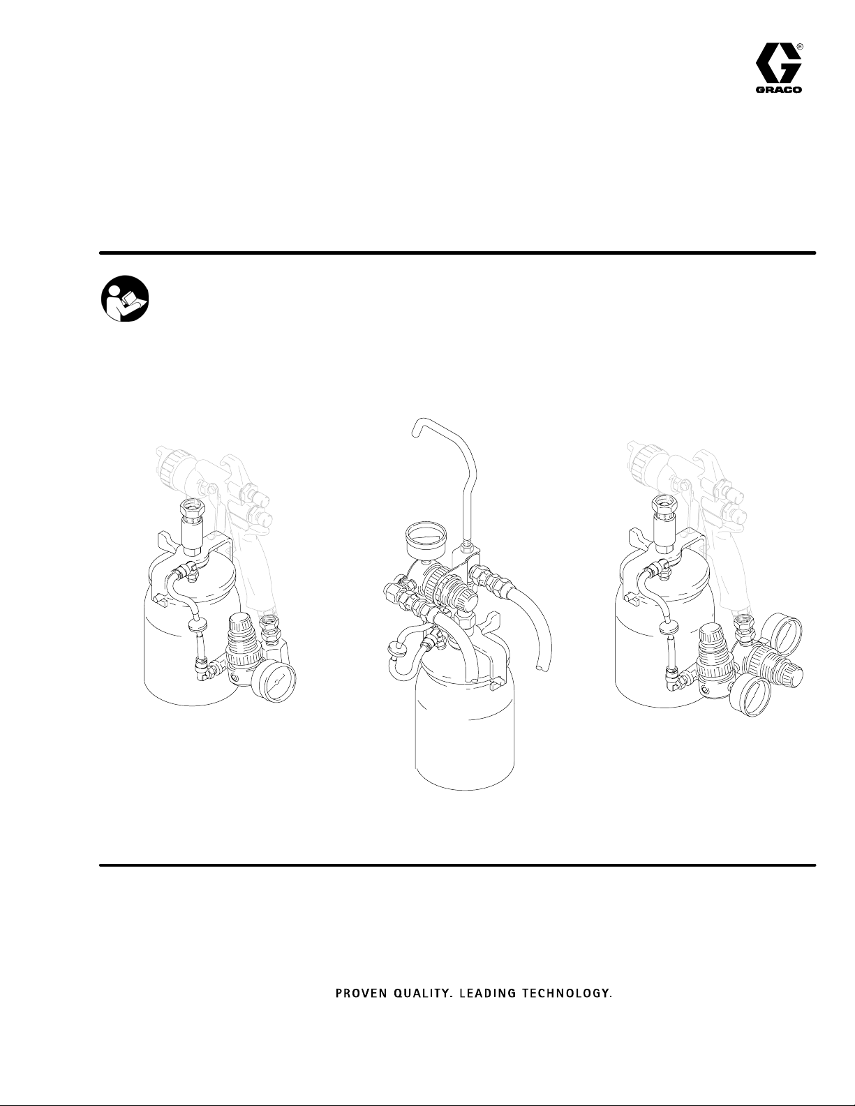
STAINLESS STEEL, ONE QUART (ONE LITER)
Air Regulated
Pressure Cups
Important Safety Instructions
Read all warnings and instructions in this manual.
Save these instructions.
See page 10 for model numbers and maximum
working pressures.
308791E
7611A
Single Air Regulator
Pressure Cup Kit
Part No. 239802 and 245181
7613A
Remote Single Air Regulator
Pressure Cup Kit
Part No. 239804
Double Air Regulator
Pressure Cup Kit
Part No. 239803
7612A
Page 2
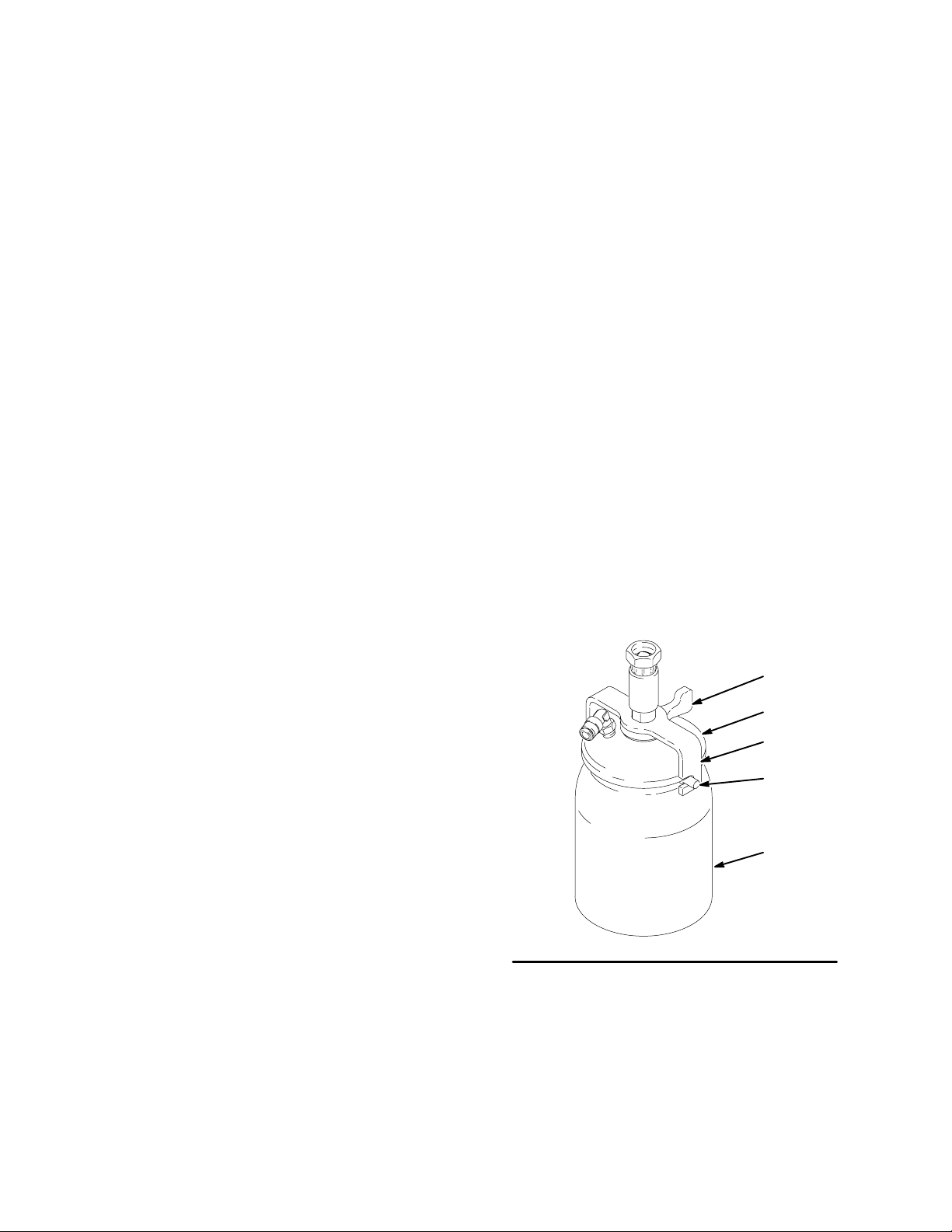
Table of Contents
A
Set-Up 2. . . . . . . . . . . . . . . . . . . . . . . . . . . . . . . . . . . . . . .
Operation 4. . . . . . . . . . . . . . . . . . . . . . . . . . . . . . . . . . . . .
Maintenance 6. . . . . . . . . . . . . . . . . . . . . . . . . . . . . . . . . .
Parts
One Quart Pressure Cup 239801 7. . . . . . . . . . . . .
Single Air Reg 7
Pressure Cup Kit 239802, 245181 7. . . . . . . . . . . .
Single Air Reg. Assembly 235375, 245192 7. . . . .
Double Air Reg. Pressure Cup Kit 239803 8. . . . . .
Setup
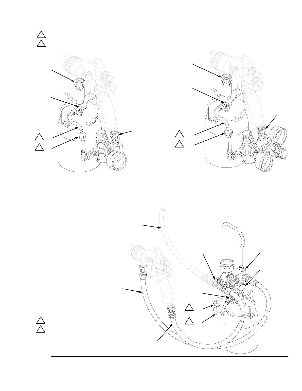
NOTE: Tighten all fittings securely.
Install the Elbow Fitting and Tubing
Push the tubing (3), with the check valve (13), firmly
into the cup’s elbow fitting (D). See Fig. 2 or 3. The
tapered side of the check valve must face towards the
cup’s elbow fitting.
NOTE: To disconnect the tubing, push down on the
fitting’s outer ring and pull on the tubing.
Part No. 239802, 239803, and 245181:
Install the Gun on the Cup
1. Tighten the cup swivel fitting (E) onto the gun fluid
inlet. See Fig. 2.
2. Tighten the air fitting (F) onto the gun air inlet.
Part No. 239804: Assemble the Remote
Single Air Regulator Pressure Cup Kit
1. Tighten the cup swivel fitting (E) onto the fluid
outlet fitting (4) of the air regulator assembly. See
Fig. 3.
2. Tighten the air supply line (G) onto the air inlet
fitting (19).
Double Air Reg. Assembly 235376 8. . . . . . . . . . . .
Remote Single Air Reg. 9. . . . . . . . . . . . . . . . . . . . .
Pressure Cup Kit 239804 9. . . . . . . . . . . . . . . . . . . .
Remote Single Air Reg. Assembly 236142 9. . . . .
Technical Data 10. . . . . . . . . . . . . . . . . . . . . . . . . . . . . . .
Accessories 11. . . . . . . . . . . . . . . . . . . . . . . . . . . . . . . . .
Warranty 12. . . . . . . . . . . . . . . . . . . . . . . . . . . . . . . . . . . .
Graco Information 12. . . . . . . . . . . . . . . . . . . . . . . . . . . .
Fill the Pressure Cup
1. Push the clamp lever (A) fully to the unclamped
position, against the yoke (B). See Fig. 1.
2. Twist the cup lid (101) counterclockwise to disengage the yoke hook from the cup extended
pins (C).
3. Remove the cup lid (101) and fill the cup with fluid.
4. Twist the cup lid (101) clockwise to engage the
yoke (B) hook, then push the clamp lever (A) fully
to the clamped position. Use your thumb to force
the clamp lever into position; do not use wrenches
or tools to move it.
A
101
B
C
103
3. Tighten the air line (H) onto the gun air inlet.
4. Tighten the fluid line (J) onto the gun fluid inlet.
2 308791
Fig. 1
01961
Page 3
Setup
1
Push tube (3) fully into elbow fitting (D)
2
Tapered side of the check valve must face towards the cup’s elbow fitting
E
D
F
1
3
2
13
E
D
F
1
3
2
13
Part No. 239802 and 245181
Single Air Regulator Pressure Cup Kit
Fig. 2
Part No. 239804
Remote Single Air Regulator
Pressure Cup Kit
7612A7611A
Part No. 239803
Double Air Regulator Pressure Cup Kit
G
19 4
E
J
D
2
13
1
Push tube (3) fully into elbow fitting (D)
2
Tapered side of the check valve must face
towards the cup’s elbow fitting
Fig. 3
1
3
H
7623A
308791 3
Page 4
WARNING
Operation
Never exceed 20 psi (1.4 bar) static air pressure to
the cup. Exceeding the maximum working pressure
of the cup or any other system component could
cause component rupture, which could result in
serious injury and property damage.
WARNING
Pressure Relief Procedure
To reduce the risk of serious injury, including splashing in the eyes or on the skin, always follow this
procedure after you stop spraying, when checking or
servicing any part of the spray system, before disconnecting the gun, air regulator, or pressure cup
and when removing a pressure cup for refilling or
cleaning.
1. Turn off the air supply to the gun.
2. Trigger the gun into a grounded metal waste
container to relieve fluid pressure.
3. Place the cup on a table and slowly release the
clamp (A) to bleed-off any residual pressure in
the cup. See Fig. 4. Be sure to push the clamp
lever fully to the clamped position before turning
on the air supply to the gun again.
Setting the Cup Air Pressure
A
Fig. 4
M
K
L
7611A
Spraying Tips
The regulator is not self relieving so if the regulated air
pressure setting is causing excessive fluid flow, follow
these steps.
1. Pull up the cup regulator adjustment knob lock-ring
(L). See Fig. 4.
2. Turn the adjustment knob (K) counterclockwise.
3. Trigger the gun into a grounded metal waste
container until cup pressure is lowered.
1. Pull up the cup regulator adjustment knob lock-ring
(L); this allows the knob (K) to turn. See Fig. 4.
2. Set the cup pressure at zero by turning the
adjustment knob (K) fully counterclockwise.
3. Slowly turn the adjustment knob (K) clockwise to
increase the air pressure to the cup.
4. Push the adjustment knob lock-ring (L) down to
lock the cup pressure setting.
Setting the Gun Air Pressure
NOTE: Installing the gun air inlet regulator adds a
pressure drop that could limit the air cap pressure.
Set the gun air pressure regulator for the minimum
pressure needed to atomize your fluid. See your gun
manual for recommended settings.
4. Turn the adjustment knob (K) clockwise until you
obtain the desired lower pressure setting.
5. Push down the adjustment knob lock-ring (L).
CAUTION
Do not restrict the fluid flow by continuously spraying
with the gun’s fluid adjustment knob (M) turned in
(clockwise) as this will cause excessive abrasive
wear on the fluid needle and trigger/air valve shaft.
To restrict the fluid flow, lower the cup pressure or use
a smaller size needle/nozzle set and air cap combination.
If the cup pressure must be below 1.0 psi (0.07 bar) to
achieve the desired fluid flow, a smaller needle/nozzle
size is recommended.
4 308791
Page 5

Operation
Optional Gun Air Regulator 235119
NOTE:
D Installing the gun air inlet regulator adds a pressure
drop that could limit the air cap pressure.
D See Accessories on page 11 for air regulator
replacement parts.
1. Pull up the gun regulator adjustment knob lock-ring
(L); this allows the knob to turn. See Fig. 5.
2. Set the gun air pressure at zero by turning the
regulator adjustment knob (K) fully counterclockwise.
3. Turn on the air supply to the gun.
L
4. Turn the regulator adjustment knob (K) clockwise
to increase the air pressure to the gun.
WARNING
Never exceed 100 psi (7 bar) Maximum Working
Air Pressure to the gun. Exceeding the maxi-
mum working pressure of the gun or any other
system component could cause component
rupture, which could result in serious injury and
property damage.
5. Push the adjustment knob lock-ring (L) down to
hold the pressure setting.
Fig. 5
K
7614A
308791 5
Page 6

Maintenance
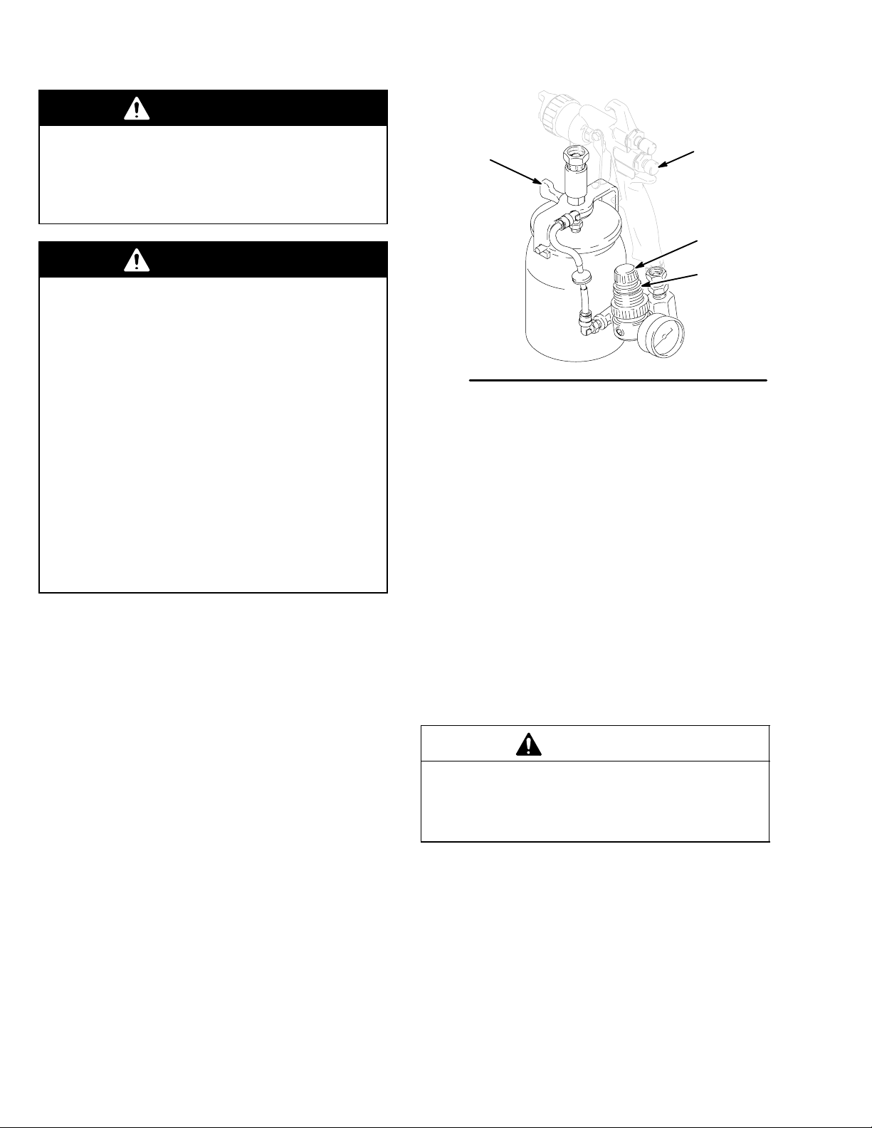
Disconnect the Gun and Air Regulator
from the Cup
1. Follow the Pressure Relief Procedure Warning
on page 4.
2. To disengage the tube grip, push down on the
outer ring of the lid elbow fitting (N), then pull the
tubing (3) out of the fitting. See Fig. 6.
3. Holding a wrench on the gun fluid inlet fitting,
disconnect the pressure cup swivel nut fitting (E).
4. Disconnect the air regulator fitting from the gun air
inlet.
5. Clean the gun as instructed in the gun manual.
CAUTION
Do not clean the air regulators in a gun washer as it
will damage the regulator diaphragm. Do not use any
cleaning method that allows solvent to enter the
regulator internally.
5. If any fluid is in the lid elbow fitting (N), flush it with
solvent but do not soak it in solvent for an
extended period.
6. If fluid is in the tubing (3) or check valve (13),
replace them. See the parts list for your cup
assembly to order parts.
E
N
3
A
101
B
102
Remove the Cup Lid
1. Push the clamp lever (A) fully to the unclamped
position, against the yoke (B). See Fig. 6.
2. Twist the cup lid (101) counterclockwise to disengage the yoke hook from the cup extended pins
(C).
3. Remove the cup lid (101).
4. Clean the cup lid (101) and cup (103).
CAUTION
When cleaning the pressure cup lid (101), avoid
prolonged exposure of the gasket (102) to solvent as
this will cause it to swell.
13
Fig. 6
C
103
3668
6 308791
Page 7

Parts
8
Use Only Genuine Graco Parts and Accessories
One Quart Pressure Cup
Part No. 239801
Includes the following parts:
Ref.
No. Part No. Description Qty.
101 236908 LID, pressure cup; Includes
item 102 1
102 189883 GASKET 1
103 239727 CUP, 1 quart (1 liter) 1
NOTE: See the Technical Data, page 10, for a list of
pressure cup materials.
101
102
Single Air Regulator Assembly
Part No. 235375, Series B
Part No. 245192
Includes the following parts:
Ref.
No. Part No. Description Qty.
1 162453 NIPPLE 1
2 156823 SWIVEL FITTING 1
3 112699 TUBE; 1/4 in. OD X 2.38 in. 1
4 187410 AIR FITTING 1
5 111500 GAUGE; 0-15 psi (0-1 bar) range 1
6 111501 REGULATOR; 0-12 psi
(0-0.8 bar) range 1
8 112698 ELBOW FITTING; 90_ swivel;
for 1/4 in. OD tube 1
9 100168 NIPPLE 1
10 110440 TEE FITTING 1
11 112059 PRESSURE RELIEF VALVE 1
12 189557 AIR RESTRICTOR 1
13 M71256 CHECK VALVE1
14 112699 TUBE, 1/4 in. OD X 2.38 in.
(235735) 1
198527 TUBE 1/4 in. OD X 6.00 in.
(245192) 1
103
01960A
Single Air Regulator Pressure Cup Kit
Includes the following parts:
Part No. 239802
Part No. Description Qty.
235375 Single Air Regulator Assembly
See parts list at right 1
239801 Pressure Cup Assembly
See parts list above 1
195065 Air Inlet Fitting
Part No. 245181
Part No. Description Qty.
245192 Single Air Regulator Assembly
See parts list at right 1
239801 Pressure Cup Assembly
See parts list above 1
195065 Air Inlet Fitting
14
3
13
11
1
3
1
9
1
8
1
1
Apply anaerobic pipe sealant (white) to external threads
2
Press fit tightly into tee (10)
3
Tapered side of the check valve must face towards the cup’s
elbow fitting
10
2
12
1
1
65
1
2
4
1
1
0172
308791 7
Page 8

Parts
A
Use Only Genuine Graco Parts and Accessories
Double Air Regulator Pressure Cup Kit
Part No. 239803
Includes the following parts:
Part No. Description Qty.
235376 Double Air Regulator Assembly
See parts list below 1
239801 Pressure Cup Assembly
See parts list, page 7 1
195065 Air Inlet Fitting 1
Double Air Regulator Assembly
Part No. 235376, Series B
Includes the following parts:
Ref.
No. Part No. Description Qty.
2 156823 SWIVEL FITTING 1
3 112699 TUBE; nylon; 1/4 in. OD 2
4 162453 NIPPLE 1
5 111500 GAUGE; 0-15 psi (0-1 bar) range 1
6 111501 REGULATOR; 0-12 psi
(0-0.8 bar) range 1
8 112698 ELBOW FITTING; 90_ swivel;
for 1/4 in. OD tube 1
9 100168 NIPPLE 1
10 110440 TEE FITTING 1
11 112059 PRESSURE RELIEF VALVE 1
12 189557 AIR RESTRICTOR 1
13 M71256 CHECK VALVE 1
14 110436 GAUGE; 0-100 psi
(0-7 bar) range 1
15 110438 REGULATOR; 0-100 psi
(0-7 bar) range 1
3
13
11
1
1
8
1
10
2
12
1
9
1
2
1
14
15
1
4
3
8 308791
1
1
Apply anaerobic pipe sealant (white) to external threads
2
Press fit tightly into tee (10)
3
Tapered side of the check valve must face towards the cup’s
elbow fitting
1
65
01729
Page 9

Parts
Use Only Genuine Graco Parts and Accessories
Remote Single Air Regulator
Pressure Cup Kit
Part No. 239804
Includes the following parts:
Part No. Description Qty.
236142 Remote Air Regulator Assembly
See parts list below 1
239801 Pressure Cup Assembly
See parts list, page 7 1
Remote Air Regulator Assembly
Part No. 236142, Series B
Includes the following parts:
Ref.
No. Part No. Description Qty.
1 172620 HOOK 1
2 100188 HEX NUT 1
Ref.
No. Part No. Description Qty.
3 172680 ELBOW FITTING 1
4 172682 HOSE ADAPTER 1
5 111500 GAUGE; 0-15 psi (0-1 bar) range 1
6 111501 REGULATOR; 0-12 psi
(0-0.8 bar) range 1
7 112698 CONNECTOR; for 1/4 in. OD tube 1
9 112699 TUBE; nylon; 1/4 in. OD 2
10 110440 TEE FITTING 1
11 112059 PRESSURE RELIEF VALVE 1
12 189557 AIR RESTRICTOR 1
13 M71256 CHECK VALVE 1
14 103656 HEX NIPPLE 1
15 212005 AIR HOSE; buna-n; 1/4 npsm;
6 ft. (1.83 m) long 1
16 212006 FLUID HOSE; nylon; 3/8 npsm;
6.5 ft. (1.98 m) long 1
17 188770 MOUNTING BRACKET 1
18 112308 PANEL NUT 1
19 183696 TEE FITTING 1
1
5
1
14
1
11
19
15
1
10
1
Apply anaerobic pipe sealant (white) to external threads
2
Press fit tightly into tee (10)
1
6
17
18
1
2
3
4
4
16
2
12
1
7
9
3
13
3
Tapered side of the check valve must face towards the cup’s
elbow fitting
4
Apply high strength anaerobic pipe sealant (green) to external
threads.
01963A
308791 9
Page 10

Technical Data
Single Air Regulator Pressure Cup Kit, Part No. 239802 and 245181
Maximum Outlet Pressure 12 psi (0.8 bar). . . . . . . . . . . . . . . . . . . . . . . . . . . . . . . . . . . . . . . . . . . . . . . . . . . . . . . . . . . .
Maximum Inlet Pressure 100 psi (7 bar) . . . . . . . . . . . . . . . . . . . . . . . . . . . . . . . . . . . . . . . . . . . . . . . . . . . . . . . . . . . . . .
Double Air Regulator Pressure Cup Kit, Part No. 239803
Cup Regulator Maximum Outlet Pressure 12 psi (0.8 bar). . . . . . . . . . . . . . . . . . . . . . . . . . . . . . . . . . . . . . . . . . . . . . .
Gun Regulator Maximum Outlet Pressure 100 psi (7 bar). . . . . . . . . . . . . . . . . . . . . . . . . . . . . . . . . . . . . . . . . . . . . . .
Maximum Inlet Pressure 100 psi (7 bar). . . . . . . . . . . . . . . . . . . . . . . . . . . . . . . . . . . . . . . . . . . . . . . . . . . . . . . . . . . . . .
Remote Single Air Regulator Pressure Cup Kit, Part No. 239804
Maximum Outlet Pressure 12 psi (0.8 bar). . . . . . . . . . . . . . . . . . . . . . . . . . . . . . . . . . . . . . . . . . . . . . . . . . . . . . . . . . . .
Maximum Inlet Pressure 100 psi (7 bar) . . . . . . . . . . . . . . . . . . . . . . . . . . . . . . . . . . . . . . . . . . . . . . . . . . . . . . . . . . . . . .
One Quart Pressure Cup, Part No. 239801
Maximum Working Pressure 20 psi (1.4 bar). . . . . . . . . . . . . . . . . . . . . . . . . . . . . . . . . . . . . . . . . . . . . . . . . . . . . . . . . .
Size 1 quart (1 liter). . . . . . . . . . . . . . . . . . . . . . . . . . . . . . . . . . . . . . . . . . . . . . . . . . . . . . . . . . . . . . . . . . . . . . . . . . . . . . . .
Material
Cup, Tube, Seat, and Nut 304 Stainless Steel. . . . . . . . . . . . . . . . . . . . . . . . . . . . . . . . . . . . . . . . . . . . . . . . . . . . .
Lid Glass–Filled Nylon. . . . . . . . . . . . . . . . . . . . . . . . . . . . . . . . . . . . . . . . . . . . . . . . . . . . . . . . . . . . . . . . . . . . . . . . . .
Sleeve, Clamp Arm Electroless Nickel Plated Aluminum. . . . . . . . . . . . . . . . . . . . . . . . . . . . . . . . . . . . . . . . . . . . .
Yoke Electroless Nickel Plated Steel. . . . . . . . . . . . . . . . . . . . . . . . . . . . . . . . . . . . . . . . . . . . . . . . . . . . . . . . . . . . .
Cup Gasket Polyethylene Foam. . . . . . . . . . . . . . . . . . . . . . . . . . . . . . . . . . . . . . . . . . . . . . . . . . . . . . . . . . . . . . . . .
Cup Fluid Nut Thread 3/8–18 npsm; R3/8–19 compound thread. . . . . . . . . . . . . . . . . . . . . . . . . . . . . . . . . . . . . . . . . . . .
Regulator Swivel Nut Thread 1/4–18 npsm; R1/4–19 compound thread. . . . . . . . . . . . . . . . . . . . . . . . . . . . . . . . . . . . .
Weight
Pressure Cup Only 1 lb. 7 oz. (646 g). . . . . . . . . . . . . . . . . . . . . . . . . . . . . . . . . . . . . . . . . . . . . . . . . . . . . . . . . . . . . . . . .
Cup with Single Air Regulator* 2 lb. 4 oz. (1007 g). . . . . . . . . . . . . . . . . . . . . . . . . . . . . . . . . . . . . . . . . . . . . . . . . . . . . .
Cup with Double Air Regulator* 2 lb. 8 oz. (1113 g). . . . . . . . . . . . . . . . . . . . . . . . . . . . . . . . . . . . . . . . . . . . . . . . . . . . .
Remote Cup with Air Regulator Assembly* 2 lb. 9 oz. (1130 g). . . . . . . . . . . . . . . . . . . . . . . . . . . . . . . . . . . . . . . . . . .
Remote Cup with Air Regulator Assembly and Hoses* 4 lb. 1 oz. (1816 g). . . . . . . . . . . . . . . . . . . . . . . . . . . . . . . . .
Gun Air Regulator* 8 oz. (224 g). . . . . . . . . . . . . . . . . . . . . . . . . . . . . . . . . . . . . . . . . . . . . . . . . . . . . . . . . . . . . . . . . . . . .
* Weight without gun
10 308791
Page 11

Accessories
Spray Gun Air Regulator Assembly 235119
100 psi (7 bar) Maximum Outlet Pressure
150 psi (10 bar) Maximum Inlet Pressure
For use on a spray gun with a 1/4–18 npsm air fitting.
Includes the following parts:
Ref.
No. Part No. Description Qty.
1 162453 NIPPLE; 1/4 npt x 1/4 npsm 1
2 156823 SWIVEL UNION; 1/4 npt 1
3 110436 GAUGE; 0-100 psi
(0-7 bar) range 1
4 110438 REGULATOR; 0-100 psi
(0-7 bar) range 1
NOTE: Installing the gun air inlet regulator adds a
pressure drop that could limit the air cap pressure.
3
1
2
Quick Disconnect Coupler 208536
1/4 npt(f), zinc-plated brass
NOTE: Installing the coupler adds a pressure drop that
could limit the air cap pressure.
Quick Disconnect Pin 169970
1/4 npt(m), zinc-plated steel
169970
Replaces nipple 162453,
item 1, at left
208536
0697
One Quart Pressure Cup Liners 112490
Box of 20 special blend polyethylene liners.
Use to line cup for easy clean-up. Graco Standard
4
01730
Warranty
308791 11
Page 12

Graco Standard Warranty
Graco warrants all equipment manufactured by Graco and bearing its name to be free from defects in material and workmanship on the
date of sale to the original purchaser for use. With the exception of any special, extended, or limited warranty published by Graco,
Graco will, for a period of twelve months from the date of sale, repair or replace any part of the equipment determined by Graco to be
defective. This warranty applies only when the equipment is installed, operated and maintained in accordance with Graco’s written
recommendations.
This warranty does not cover, and Graco shall not be liable for general wear and tear, or any malfunction, damage or wear caused by
faulty installation, misapplication, abrasion, corrosion, inadequate or improper maintenance, negligence, accident, tampering, or substitution of non–Graco component parts. Nor shall Graco be liable for malfunction, damage or wear caused by the incompatibility of
Graco equipment with structures, accessories, equipment or materials not supplied by Graco, or the improper design, manufacture,
installation, operation or maintenance of structures, accessories, equipment or materials not supplied by Graco.
This warranty is conditioned upon the prepaid return of the equipment claimed to be defective to an authorized Graco distributor for
verification of the claimed defect. If the claimed defect is verified, Graco will repair or replace free of charge any defective parts. The
equipment will be returned to the original purchaser transportation prepaid. If inspection of the equipment does not disclose any defect
in material or workmanship, repairs will be made at a reasonable charge, which charges may include the costs of parts, labor, and
transportation.
THIS WARRANTY IS EXCLUSIVE, AND IS IN LIEU OF ANY OTHER WARRANTIES, EXPRESS OR IMPLIED, INCLUDING BUT
NOT LIMITED TO WARRANTY OF MERCHANTABILITY OR WARRANTY OF FITNESS FOR A PARTICULAR PURPOSE.
Graco’s sole obligation and buyer’s sole remedy for any breach of warranty shall be as set forth above. The buyer agrees that no other
remedy (including, but not limited to, incidental or consequential damages for lost profits, lost sales, injury to person or property, or any
other incidental or consequential loss) shall be available. Any action for breach of warranty must be brought within two (2) years of the
date of sale.
Graco makes no warranty, and disclaims all implied warranties of merchantability and fitness for a particular purpose in connection
with accessories, equipment, materials or components sold but not manufactured by Graco. These items sold, but not manufactured
by Graco (such as electric motors, switches, hose, etc.), are subject to the warranty, if any, of their manufacturer. Graco will provide
purchaser with reasonable assistance in making any claim for breach of these warranties.
In no event will Graco be liable for indirect, incidental, special or consequential damages resulting from Graco supplying equipment
hereunder, or the furnishing, performance, or use of any products or other goods sold hereto, whether due to a breach of contract,
breach of warranty, the negligence of Graco, or otherwise.
FOR GRACO CANADA CUSTOMERS
The parties acknowledge that they have required that the present document, as well as all documents, notices and legal proceedings
entered into, given or instituted pursuant hereto or relating directly or indirectly hereto, be drawn up in English. Les parties reconnaissent avoir convenu que la rédaction du présente document sera en Anglais, ainsi que tous documents, avis et procédures judiciaires
exécutés, donnés ou intentés à la suite de ou en rapport, directement ou indirectement, avec les procedures concernées.
Graco Information
TO PLACE AN ORDER, contact your Graco distributor, or call one of the following numbers
to identify the distributor closest to you:
1–800–328–0211 Toll Free
612–623–6921
612–378–3505 Fax
All written and visual data contained in this document reflects the latest product information available at the time of publication.
Graco reserves the right to make changes at any time without notice.
This manual contains English. MM 308791
International Offices: Belgium, China, Japan, Korea
GRACO INC.ąP.O. BOX 1441ąMINNEAPOLIS, MNą55440-1441
Graco Headquarters: Minneapolis
Copyright 1977, Graco Inc. is registered to I.S. EN ISO 9001
www.graco.com
Revised March 2008
12 308791
 Loading...