

Page 1
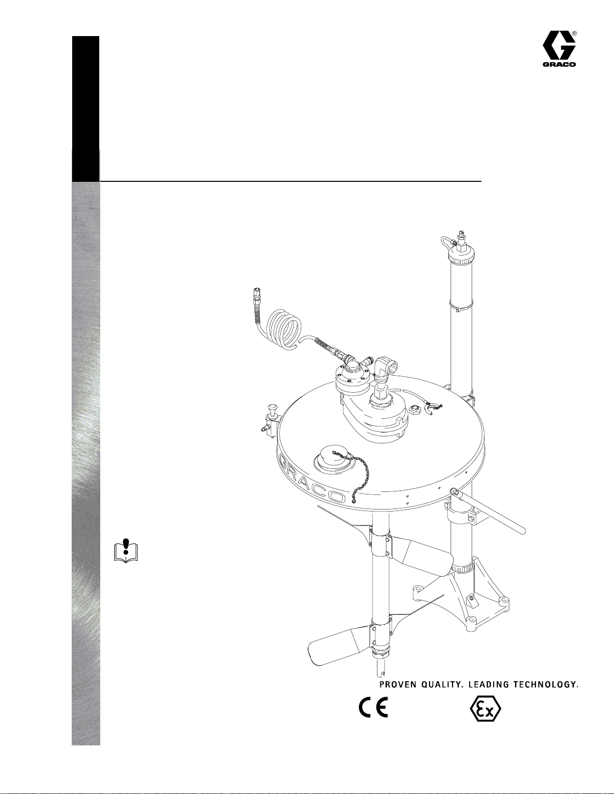
Instructions – Parts List
Parts
55 GALLON (200 LITER) DRUM SIZE
239857 Supply Module
Includes elevator, stainless steel drum cover,
and back-geared agitator
100 psi (0.7 MPa, 7 bar) Maximum Air Input Pressure
This module fits the following pump modules:
Part No. 232078
SST 3:1 President Module
Part No. 232079
CST 3:1 President Module
Part No. 232081
SST 3:1 President Module
Part No. 232080
SST Husky 1040 Module
Part No. 232082
SST Husky 1040 Module
308769D
Read warnings and instructions.
See page 2 for table of contents.
GRACO INC.ąP.O. BOX 1441ąMINNEAPOLIS, MNą55440-1441
Copyright 1998-1997, Graco Inc. is registered to I.S. EN ISO 9001
7707A
0359
II 1/2 G T6
ITS03ATEX11251
Page 2
Table of Contents
Symbols
Warnings 2. . . . . . . . . . . . . . . . . . . . . . . . . . . . . . . . . . . . . .
Installation 5. . . . . . . . . . . . . . . . . . . . . . . . . . . . . . . . . . . . .
Operation 10. . . . . . . . . . . . . . . . . . . . . . . . . . . . . . . . . . . .
Parts 12. . . . . . . . . . . . . . . . . . . . . . . . . . . . . . . . . . . . . . . .
Technical Data 14. . . . . . . . . . . . . . . . . . . . . . . . . . . . . . . .
Dimensions 14. . . . . . . . . . . . . . . . . . . . . . . . . . . . . . . . . . .
Mounting Hole Layout 15. . . . . . . . . . . . . . . . . . . . . . . . . .
Graco Warranty 16. . . . . . . . . . . . . . . . . . . . . . . . . . . . . . .
Graco Information 16. . . . . . . . . . . . . . . . . . . . . . . . . . . . .
WARNING
EQUIPMENT MISUSE HAZARD
Equipment misuse can cause the equipment to rupture or malfunction and result in serious injury.
INSTRUCTIONS
D This equipment is for professional use only.
Warning Symbol
WARNING
This symbol alerts you to the possibility of serious
injury or death if you do not follow the instructions.
Caution Symbol
CAUTION
This symbol alerts you to the possibility of damage to
or destruction of equipment if you do not follow the
instructions.
D Read all instruction manuals, tags, and labels before operating the equipment.
D Use the equipment only for its intended purpose. If you are uncertain about usage, call your Graco
distributor.
D Do not alter or modify this equipment. Use only genuine Graco parts and accessories.
D Check equipment daily. Repair or replace worn or damaged parts immediately.
D Do not exceed the maximum working pressure stated on the equipment or in the Technical Data
for your equipment. Do not exceed the maximum working pressure of the lowest rated component
in your system.
D Use fluids and solvents which are compatible with the equipment wetted parts. Refer to the Tech-
nical Data section of all equipment manuals. Read the fluid and solvent manufacturer’s warnings.
D Route hoses away from traffic areas, sharp edges, moving parts, and hot surfaces. Do not expose
Graco hoses to temperatures above 180_F (82_C) or below –40_F (–40_C).
D Wear hearing protection when operating this equipment.
D Do not lift pressurized equipment.
D Comply with all applicable local, state, and national fire, electrical, and safety regulations.
2 308769
Page 3
WARNING
FIRE AND EXPLOSION HAZARD
Improper grounding, poor ventilation, open flames or sparks can cause a hazardous condition and
result in a fire or explosion and serious injury.
D Ground the equipment and the object being sprayed. Refer to Grounding on page 8.
D If there is any static sparking or you feel an electric shock while using this equipment, stop spray-
ing immediately. Do not use the equipment until you identify and correct the problem.
D Provide fresh air ventilation to avoid the buildup of flammable fumes from solvents or the fluid
being sprayed.
D Keep the spray area free of debris, including solvent, rags, and gasoline.
D Electrically disconnect all equipment in the spray area.
D Extinguish all open flames or pilot lights in the spray area.
D Do not smoke in the spray area.
D Do not turn on or off any light switch in the spray area while operating or if fumes are present.
D Do not operate a gasoline engine in the spray area.
TOXIC FLUID HAZARD
Hazardous fluid or toxic fumes can cause serious injury or death if splashed in the eyes or on the skin,
inhaled, or swallowed.
D Know the specific hazards of the fluid you are using.
D Store hazardous fluid in an approved container. Dispose of hazardous fluid according to all local,
state and national guidelines.
D Always wear protective eyewear, gloves, clothing and respirator as recommended by the fluid and
solvent manufacturer.
308769 3
Page 4

WARNING
PRESSURIZED EQUIPMENT HAZARD
Spray from the gun, hose leaks, or ruptured components can splash fluid in the eyes or on the skin
and cause serious injury.
D Do not point the gun at anyone or at any part of the body.
D Do not stop or deflect leaks with your hand, body, glove or rag.
D Follow the Pressure Relief Procedure on page 10 whenever you: are instructed to relieve pres-
sure; stop spraying; clean, check, or service the equipment; and install or clean the spray tip.
D Tighten all fluid connections before operating the equipment.
D Check the hoses, tubes, and couplings daily. Replace worn, damaged, or loose parts immediately.
Permanently coupled hoses cannot be repaired; replace the entire hose.
MOVING PARTS HAZARD
Moving parts, such as the air motor piston, elevator, and agitator blades, can pinch or amputate your
fingers.
D Keep clear of all moving parts when starting or operating the pump.
D Keep your hands away from the elevator, pump support, drum cover, and the lip of the drum while
the elevator is operating or is charged with air.
D Always shut off the agitator and disconnect the air line before you remove the agitator from the
drum or check or repair any part of the agitator.
D Before servicing the equipment, follow the Pressure Relief Procedure on page 10 to prevent the
equipment from starting unexpectedly.
4 308769
Page 5

WARNING
Installation
Prepare the Site
FIRE AND EXPLOSION HAZARD
Always maintain a minimum of 1 in.
clearance between rotating agitator parts
and container to prevent sparks from
contact.
General Information
NOTE: Reference numbers and letters in parentheses
in the text refer to the callouts in the figures and the
parts drawing.
NOTE: Always use Genuine Graco Parts and Accessories, available from your Graco distributor. If you
supply your own accessories, be sure they are adequately sized and pressure-rated for your system.
Prepare the Operator
All persons who operate the equipment must be
trained in the safe, efficient operation of all system
components as well as the proper handling of all fluids.
All operators must thoroughly read all instruction
manuals, tags, and labels before operating the equipment.
Select a site with at least 9 ft (2.8 m) overhead clearance for the elevator when fully raised.
Ensure that the wall is strong enough to support the
weight of the pump and accessories, fluid, hoses, and
stress caused during pump operation.
Refer to Fig. 1. Bring a compressed air supply line (A)
from the air compressor to the supply module location.
Be sure all air hoses are properly sized and pressurerated for your system. Use only electrically conductive
hoses. The air hose should have a 3/8 npt(m) thread.
Install a bleed-type shutoff valve (B) in the air line to
isolate the air line components for servicing. Install a
moisture trap and drain valve (C) to help remove
moisture and contaminants from the compressed air
supply.
The following manuals are included with this equipment:
D 308769, Supply Module
D 306287, Elevator
D 308466, Drum Cover
D 308609, Back-Geared Agitator
Keep the site clear of any obstacles or debris that
could interfere with the operator’s movement.
Have a grounded, metal pail available for use when
flushing the system.
308769 5
Page 6

Installation
Installing the 239857 Supply Module
NOTE: Refer to Fig. 1 and to the Dimension drawing
on page 14 and the Mounting Hole Layout on page 15.
1. Ensure that there is at least 9 ft (2.8 m) overhead
clearance for the elevator (150) when fully raised.
WARNING
To reduce the risk of serious injury whenever you
are instructed to relieve pressure, always follow the
Pressure Relief Procedure on page 10.
2. Remove and discard the existing suction tube at
the end of suction hose (H).
3. Locate the elevator (150) so the pump’s suction
hose (H) will reach the swivel (101) at the top of
the back-geared agitator (102). The suction hose
is 6 ft (1.8 m) long. Do not stretch the hose tight;
let it hang as shown in Fig. 1, to assist fluid flow
into the pump.
4. See page 15. Using the elevator base as a template, mark the floor. Drill four holes in the floor for
1/2 in. bolts. Make sure the bolts are long enough
to prevent the elevator from tipping.
5. Connect the suction hose to the swivel outlet (101)
of the agitator (102). Connect the suction hose
ground wire to the ground lug on the agitator as
shown on page 8.
6. Loosen the captive screw and open the quick
connector (F) on the air filter/regulator/lubricator
assembly (G).
7. Slide the pipe adapter (J) out of the quick connector (F). Remove and discard the pipe plug from the
bottom port of the tee (K).
8. Bring the coiled hose (105) up through the large
hole in the back pressure regulator’s bracket (E).
9. Screw the adapter (159) at the end of the coiled
hose (105) into the tee (K).
10. Slide the pipe adapter (J) into the quick connector
(F), close, and tighten the captive screw.
Supplied Components
Refer to Fig. 1.
D Fluid is supplied to the pump through the suction
tube (109). The suction tube is installed in the shaft
of the agitator (102). See Fig. 1.
D The back-geared agitator (102) keeps the fluid in
suspension and also includes a suction tube (109)
to draw fluid from a 55 gallon drum.
D The air-operated elevator (150) allows you to
raise the drum cover and agitator from an empty
drum, replace the drum, and lower the agitator into
the new drum.
D The stainless steel drum cover (114) fits a 55
gallon (200 liter) drum.
6 308769
Page 7

Installation
B
A
Detail of Air Controls
C
K
105
108
159
J
G
F
150
1
4
2
101
E
102
114
Fig. 1
109
Supply Module Shown with
3:1 President Pump Module
Ensure that there is 9 ft (2.8 m) overhead clearance
H
3
1
for the elevator when fully raised.
Mount the pump module so the top of the bracket is
2
4 to 5 ft (1.2 to 1.5 m) above the floor.
The suction hose is 6 ft (1.8 m) long. Do not stretch
3
the hose tight; let it hang as shown, to assist fluid
flow into the pump.
See Detail of Air Controls in upper left corner.
4
7704B
308769 7
Page 8

Grounding
Installation
WARNING
FIRE AND EXPLOSION HAZARD
Before operating the pump, ground the
system as explained below. Also read
the section FIRE AND EXPLOSION
HAZARD on page 3.
1. Pump: refer to the grounding instructions in your
separate pump manual.
2. Air and fluid hoses: use only electrically conductive
hoses.
3. Air compressor: follow manufacturer’s recommendations.
4. Spray gun: ground through connection to a properly grounded fluid hose and pump.
5. Agitator: remove the ground screw (Z) and insert
through the eye of the ring terminal at end of
ground wire (Y). Fasten the ground screw back
onto the pump and tighten securely. Connect the
other end of the ground wire to a true earth
ground. See Fig. 2. To order a ground wire and
clamp, order Part No. 222011.
Z
Fig. 2
6. Suction hose: attach the hose ground wire to the
ground lug on the agitator. See Fig. 2. If you are
not using an agitator, attach the wire to the fluid
supply container.
7. Fluid supply container: follow your local code.
8. Object being sprayed: follow your local code.
9. Solvent pails used when flushing: follow your local
code. Use only metal pails, which are conductive,
placed on a grounded surface. Do not place the
pail on a nonconductive surface, such as paper or
cardboard, which interrupts the grounding continuity.
10. To maintain grounding continuity when flushing or
relieving pressure, hold a metal part of the spray
gun firmly to the side of a grounded metal pail,
then trigger the gun.
Y
TI1052
8 308769
Page 9

Notes
308769 9
Page 10

Operation
Pressure Relief Procedure
WARNING
PRESSURIZED EQUIPMENT HAZARD
The system pressure must be manually relieved to
prevent the system from starting or spraying accidentally. To reduce the risk of an injury from accidental spray from the gun, splashing fluid, or
moving parts, follow the Pressure Relief Proce-
dure whenever you:
D are instructed to relieve the pressure,
D stop spraying,
D check or service any of the system equipment,
D or install or clean the spray nozzle.
1. Press down the air control valve (P) button. Lower
the elevator until the cover (114) rests properly on
the lip of the drum. Disconnect the quick coupler
(124) from the male fitting (D) on the air control
valve.
2. Relieve the air and fluid pressure, following the
instructions in your separate pump manual.
Elevator Operation
2. Position a full drum under the drum cover (114).
3. To lower the elevator (150), press down the air
control valve (P) button. Lower the elevator until
the cover (114) rests properly on the lip of the
drum. Disconnect the quick coupler (124) from the
male fitting (D).
4. Refer to manual 306287 for further elevator operating instructions.
Agitator Operation
1. Close the agitator’s needle valve (L).
2. Connect the quick coupler (124) on the end of the
coiled hose (105) to the male fitting (M) on the
agitator (102).
3. Slowly open the needle valve (L) to start the
agitator (102). Use the valve to adjust the speed.
Do not operate the agitator too fast. If the fluid
foams or a vortex forms on the fluid surface,
reduce the speed of the agitator.
1. To raise the elevator (150), connect the quick
coupler (124) on the end of the coiled hose (105)
to the male fitting (D) on the air control valve (P).
Pull up the air control valve button to raise the
elevator to its full height.
WARNING
MOVING PARTS HAZARD
Moving parts can pinch or amputate your
fingers. When raising or lowering the
elevator, keep your fingers and hands
away from the elevator (150), cover support (125),
drum cover (114), and lip of the drum.
Do not remove the quick coupler (124) from the
male fitting (D) until the elevator is completely
lowered.
4. Refer to manual 308609 for further agitator operating instructions.
Shutdown
WARNING
To reduce the risk of serious injury whenever you
are instructed to relieve pressure, always follow the
Pressure Relief Procedure on page 10.
1. Lower the elevator (150).
2. Shut off the agitator (102).
3. Relieve the pressure.
10 308769
Page 11

105
124
Operation
150
M
L
P
114
D
102
125
Fig. 3
7688B
308769 11
Page 12

Parts
Part No. 239857, Series A, Supply Module
159
105
159 (Ref)
105 (Ref)
134
102
124
104
103
109
108
155 (Ref)
101
155
150
107
125
B
B
114
102 (Ref)
12 308769
109 (Ref)
7686B
Page 13

Parts
Part No. 239857, Series A, Supply Module
Ref.
No. Description Part No. Qty
101 SWIVEL; sst; 3/4 npt (m x f) 112268 1
102 AGITATOR, back-geared; see manual 308609 238157 1
103 BUSHING; sst; 1” npt(m) x 3/4 npt(f) 502851 1
104 ELBOW, 90_; sst; 1” npt (fbe) 500251 1
105 HOSE, air; nylon; 1/4 in. (6 mm) ID; 1/4 npt (mbe); 50 ft (15.2 m) long 205600 1
107 STRAP, tie 103546 3
108 GROUND WIRE AND CLAMP 222011 1
109 RISER TUBE KIT; see manual 308609 238250 1
114 COVER, drum; sst; see manual 308466 238283 1
124 COUPLER, quick disconnect, female 114558 1
125 ASSEMBLY, cover support; see manual 306287 237578 1
134 KIT, air control, elevator; see manual 306287 237579 1
150 ELEVATOR, drum; see manual 306287 204385 1
155 KIT, return tube 238884 1
159 ADAPTER; 3/8 npt(m) x 1/4 npt(f) 159841 1
308769 13
Page 14

Technical Data
Category Data
Maximum air input pressure 100 psi (0.7 MPa, 7 bar)
Weight approximately 100 lb (45 kg)
Wetted parts Back-Geared Agitator: See agitator manual 308609.
Drum Cover: Stainless Steel
Fluid Hoses: Nylon
Dimensions
Ensure that there is 9 ft (2.8 m) overhead clearance
1
for the elevator when fully raised.
1
7707A
14 308769
Page 15

Mounting Hole Layout
5.5 in.
(140 mm)
8.88 in.
(225.9 mm)
0.56 in. (14.2 mm) Holes
06533
308769 15
Page 16

Graco Standard Warranty
Graco warrants all equipment manufactured by Graco and bearing its name to be free from defects in material and workmanship on the
date of sale by an authorized Graco distributor to the original purchaser for use. With the exception of any special, extended, or limited
warranty published by Graco, Graco will, for a period of twelve months from the date of sale, repair or replace any part of the equipment
determined by Graco to be defective. This warranty applies only when the equipment is installed, operated and maintained in accordance with Graco’s written recommendations.
This warranty does not cover, and Graco shall not be liable for general wear and tear, or any malfunction, damage or wear caused by
faulty installation, misapplication, abrasion, corrosion, inadequate or improper maintenance, negligence, accident, tampering, or substitution of non–Graco component parts. Nor shall Graco be liable for malfunction, damage or wear caused by the incompatibility of
Graco equipment with structures, accessories, equipment or materials not supplied by Graco, or the improper design, manufacture,
installation, operation or maintenance of structures, accessories, equipment or materials not supplied by Graco.
This warranty is conditioned upon the prepaid return of the equipment claimed to be defective to an authorized Graco distributor for
verification of the claimed defect. If the claimed defect is verified, Graco will repair or replace free of charge any defective parts. The
equipment will be returned to the original purchaser transportation prepaid. If inspection of the equipment does not disclose any defect
in material or workmanship, repairs will be made at a reasonable charge, which charges may include the costs of parts, labor, and
transportation.
THIS WARRANTY IS EXCLUSIVE, AND IS IN LIEU OF ANY OTHER WARRANTIES, EXPRESS OR IMPLIED, INCLUDING BUT
NOT LIMITED TO WARRANTY OF MERCHANTABILITY OR WARRANTY OF FITNESS FOR A PARTICULAR PURPOSE.
Graco’s sole obligation and buyer’s sole remedy for any breach of warranty shall be as set forth above. The buyer agrees that no other
remedy (including, but not limited to, incidental or consequential damages for lost profits, lost sales, injury to person or property, or any
other incidental or consequential loss) shall be available. Any action for breach of warranty must be brought within two (2) years of the
date of sale.
Graco makes no warranty, and disclaims all implied warranties of merchantability and fitness for a particular purpose in connection
with accessories, equipment, materials or components sold but not manufactured by Graco. These items sold, but not manufactured
by Graco (such as electric motors, switches, hose, etc.), are subject to the warranty, if any, of their manufacturer. Graco will provide
purchaser with reasonable assistance in making any claim for breach of these warranties.
In no event will Graco be liable for indirect, incidental, special or consequential damages resulting from Graco supplying equipment
hereunder, or the furnishing, performance, or use of any products or other goods sold hereto, whether due to a breach of contract,
breach of warranty, the negligence of Graco, or otherwise.
FOR GRACO CANADA CUSTOMERS
The parties acknowledge that they have required that the present document, as well as all documents, notices and legal proceedings
entered into, given or instituted pursuant hereto or relating directly or indirectly hereto, be drawn up in English. Les parties reconnaissent avoir convenu que la rédaction du présente document sera en Anglais, ainsi que tous documents, avis et procédures judiciaires
exécutés, donnés ou intentés à la suite de ou en rapport, directement ou indirectement, avec les procedures concernées.
Graco Information
TO PLACE AN ORDER, contact your Graco distributor, or call this number to identify the distributor closest to you:
1–800–328–0211 Toll Free
All written and visual data contained in this document reflects the latest product information available at the time of publication.
Graco reserves the right to make changes at any time without notice.
Foreign Offices: Belgium, Canada, England, Korea, France, Germany, China, Japan
Sales Office: Minneapolis
GRACO INC. P.O. BOX 1441 MINNEAPOLIS, MN 55440–1441
http://www.graco.com
e1998–1997 Graco Inc. 308769 Rev. D 10/2004 PRINTED IN U.S.A.
16 308769
 Loading...