

Page 1
Instructions–Parts List
IM5™ Inline Electronic Meter
For use with petroleum-based and synthetic oils, antifreeze, and
windshield washer fluid only
Model 239824
500 psi (3.4 MPa, 34 bar) Maximum Working Pressure
5 gpm (19 lpm) Maximum Flow Rate
Important Safety Instructions
Read all warnings and instructions in this manual.
Save these instructions.
Contents
Warnings 2. . . . . . . . . . . . . . . . . . . . . . . . . . . . . . . .
Installation 4. . . . . . . . . . . . . . . . . . . . . . . . . . . . . . .
Operation 6. . . . . . . . . . . . . . . . . . . . . . . . . . . . . . . .
Service 8. . . . . . . . . . . . . . . . . . . . . . . . . . . . . . . . . .
Troubleshooting 10. . . . . . . . . . . . . . . . . . . . . . . . . .
Parts 10. . . . . . . . . . . . . . . . . . . . . . . . . . . . . . . . . . .
Accessories 11. . . . . . . . . . . . . . . . . . . . . . . . . . . . .
Technical Data 11. . . . . . . . . . . . . . . . . . . . . . . . . . .
Graco Standard Warranty 12. . . . . . . . . . . . . . . . .
Graco Phone Number 12. . . . . . . . . . . . . . . . . . . . .
308687H
3172585
Conforms
to FM 3610
Cert. to CAN/CSA Std C22.2
No. 157
INTRINSICALLY SAFE
APPARATUS AND ASSOCIATED
APPARATUS FOR USE IN CLASS 1,
DIVISION 2, GROUP C, D, T6
Page 2
Symbols
Warning Symbol
WARNING
This symbol alerts you to the possibility of serious
injury or death if you do not follow the instructions.
WARNING
WARNING
EQUIPMENT MISUSE HAZARD
Equipment misuse can cause the equipment to rupture or malfunction and result in serious injury.
INSTRUCTIONS
D This equipment is for professional use only.
D Read all instruction manuals, tags, and labels before you operate this equipment.
D Use the equipment only for its intended purpose. If you are not sure, call your Graco distributor.
D Do not alter or modify this equipment. Use only genuine Graco parts and accessories.
Caution Symbol
CAUTION
This symbol alerts you to the possibility of damage to
or destruction of equipment if you do not follow the
instructions.
D Check equipment daily. Repair or replace worn or damaged parts immediately.
D Do not exceed the maximum working pressure of the lowest rated system component. See the
Technical Data on page 11 for the maximum working pressure of this component.
D Use fluids and solvents that are compatible with the equipment wetted parts. See the Technical
Data section of all equipment manuals. Read the fluid and solvent manufacturer’s warnings.
D Route hoses away from traffic areas, sharp edges, moving parts, and hot surfaces. Do not
expose Graco hoses to temperatures above 180_ F (82_ C) or below –40_ F (–40_ C).
D Comply with all applicable local, state, and national fire, electrical, and safety regulations.
D Do not use 1,1,1–trichloroethane, methylene chloride, other halogenated hydrocarbon solvents,
or fluids containing such solvents in pressurized aluminum equipment. Such use could result in a
chemical reaction, with the possibility of explosion.
D Do not use hoses to pull equipment.
D Do not lift pressurized equipment.
D Follow the Pressure Relief Procedure on page 10 before you clean, check, or service this
equipment.
D Tighten all fluid connections before you operate this equipment.
D Check the hoses, tubes, and couplings daily. Replace worn or damaged parts immediately. Do
2 308687
not repair high pressure couplings; you must replace the entire hose.
Page 3
WARNING
WARNING
FIRE AND EXPLOSION HAZARD
Improper grounding, poor ventilation, open flames, or sparks can cause a hazardous condition and
result in a fire or explosion and serious injury.
D Be sure the entire fluid system is properly grounded. Refer to your pump instruction manual for
complete details. See Grounding on page 5.
D If there is any static sparking or you feel an electric shock while using this equipment, stop dis-
pensing immediately. Do not use the equipment until you identify and correct the problem.
D Provide fresh air ventilation to avoid the buildup of flammable fumes from solvents or the fluid
being dispensed.
D Keep the dispensing area free of debris, including solvent, rags, and spilled gasoline.
D Do not smoke while dispensing flammable fluids.
D You must use one of the battery types as specified in Replacing the Battery on page 8. Use of
any other batteries than those specified could affect the intrinsic safety of this unit.
SKIN INJECTION HAZARD
Fluid from the dispensing valve, leaks, or ruptured components can inject fluid into your body and
cause extreme injury, including the need for amputation. Fluid splashed in the eyes or on the skin
can also cause serious injury.
D Fluid injected into the skin might look like a minor cut, but it is a serious injury. Get immediate
surgical treatment.
D Do not point the dispensing valve at anyone or at any part of the body.
D Do not put your hand or fingers over the dispensing valve nozzle.
D Do not stop or deflect leaks with your hand, body, glove, or rag.
D Use only extensions and automatic tips that are designed for use with your dispensing valve.
D A thermal pressure relief valve is required in closed systems of which this meter is a part.
3308687
Page 4
Installation
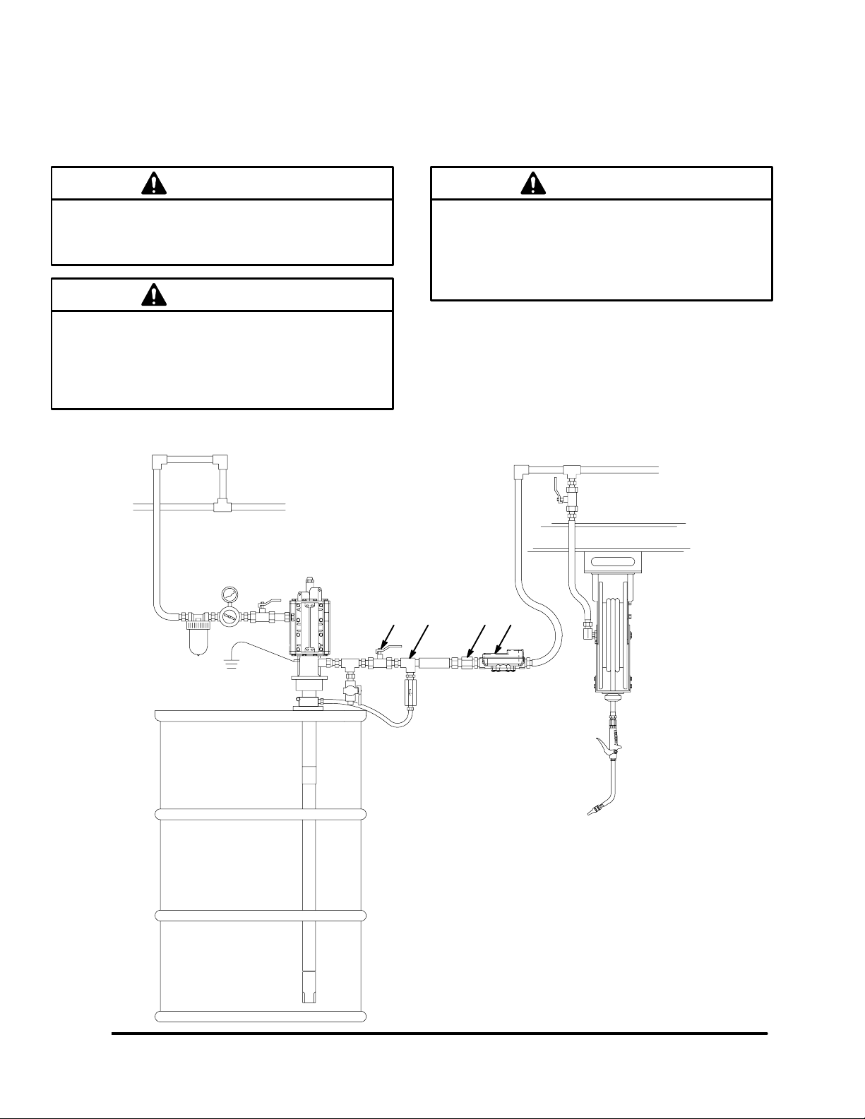
These meters must be installed in-line as part of a dispense system as shown in Fig. 1. The typical installation
shown is only a guide for selecting and installing an in-line meter; it is not an actual system design. Contact your
Graco distributor for assistance in designing a system to suit your needs.
CAUTION
To prevent line contamination, which can cause
equipment malfunction or damage, flush the lines
before you install this equipment in the system.
CAUTION
The use of this meter with a control valve and a
manual shut-off nozzle is prohibited in systems
where the operating pressure exceeds the
maximum pressure of the meter or any other
component in the system.
CAUTION
The use of PTFE tape on threaded connections to
the meter is not recommended. Such use could
contribute to overtightening of the parts and cause
the meter housing to crack. Standard pipe thread
compound is recommended.
Fig. 1
A
BCD
KEY
A Shut-off valve
B Thermal relief valve (required; Part No. 235998)
Install downstream from pump.
C In-line filter
D in-line electronic meter
7263A
4 308687
Page 5

Installation
Grounding
CAUTION
The use of PTFE tape on threaded connections to
the meter is not recommended, because it could
interrupt the grounding continuity of the system.
Standard pipe thread compound is recommended.
Proper grounding is an essential part of maintaining a
safe system.
To reduce the risk of static sparking, ground all system
components per local and national electrical codes.
See the user manuals for the pump and other system
components to ground the following:
D Pump: Follow the manufacturer’s recommenda-
tions.
D Air and fluid hoses: Use only grounded hoses.
D Air compressor: Follow the manufacturer’s recom-
mendations.
D Fluid supply container: Follow your local code.
Factory Settings
The meter is factory calibrated for 10W–30 oil, and the
default unit of measurement is quarts. For other fluids
and different units of measurement, see Changing the
Measurement Units and Calibration Factor on
page 7.
D To maintain grounding continuity when you flush or
relieve pressure, always hold a metal part of the
valve firmly to the side of a grounded metal pail,
then trigger the valve.
5308687
Page 6

Operation
Sleep Mode
The meter automatically shuts down the display after
one minute of non-use.
Activation Mode
There are two ways to activate the display:
D Press any button on the keypad to wake up the
digital display. The amount displayed is the value
stored when the meter went into sleep mode.
D Dispense fluid through the meter to wake up the
digital display. Dispensing fluid through the meter
causes the meter to count up from the last displayed value. See Fig. 2.
Function of TOTAL
Press and hold the TOTAL key to see the accumulated
total of fluid dispensed through the meter.
The accumulated total is shown in gallons when the
unit of measurement is set in gallons, quarts, or pints.
The accumulated total is shown in liters when the
measurement is set in liters. The meter accumulates a
running total of up to 99,999 gallons (or liters)
dispensed before returning to zero. See Fig. 3.
Function of RESET
Press and hold the RESET key to clear the digital
display after each dispense cycle.
Example of Total for Last Dispense Cycle
Fig. 2
Example of Accumulated Total
Fig. 3
LITERS
PINTS
L
NOTE: Always press the RESET key to clear the
digital display before each new dispense cycle.
For Maximum Dispensing Accuracy
Set the meter to dispense in pints or quarts when
dispensing 1 gallon (3.8 liters) or less.
Measurement Units
Fig. 4 shows the various measurement units as they
appear on the display.
6 308687
QUARTS
GALLONS
Examples of Measurement Units
Fig. 4
Page 7

Operation
Changing the Measurement Units and Calibration Factor
NOTE: A one liter Weights and Measures ap-
proved container is required for calibration.
This meter is factory calibrated to dispense 10W–30
motor oil at 70_ F (21_ C) at 2.0 gpm (7.6 lpm) and is
acceptably accurate for most common fluids over a
typical temperature range. If you will use the meter to
dispense antifreeze or other approved fluids, you may
have to recalibrate it for greater accuracy.
1. Press and hold both the TOTAL and RESET
buttons for four seconds.
The numbers on the display turn off, and the
L (for liters) and CAL (for calibration) icons turn
on.
2. Set the units of measurement by repeatedly press-
ing the RESET button until the correct unit of
measurement is displayed. See the list below:
GAL = gallons
QTS = quarts
PTS = pints
L = liters
3. Press the TOTAL button to go to the CALIBRA-
TION menu.
4. Dispense exactly one liter of fluid into a calibrated
1-liter container. For proper calibration, you must
dispense exactly 1 liter according to the markings
on the container.
NOTE: If you dispense more than 1 liter, press
the TOTAL button to exit the CALIBRATION
menu. Pressing the TOTAL button at this point
does not save the new calibration factor. You must
complete steps 1 to 5 change the calibration
factor.
5. Press the RESET button to store the new calibration factor and resume normal operation.
NOTE: The number on the display is the calibration factor number. It must be in the range of 311
to 466. The following table lists approximate
calibration factors for different fluids. Your calibration number may vary slightly due to temperature
or flow rate.
Fluid Calibration Number
oil (10W–30) 389
gear lube 389
automatic transmission
fluid
389
NOTE: If you do not want to change the calibration factor, press the TOTAL button again to use
the existing calibration factor and to resume normal operation. To change the calibration factor,
do steps 4 and 5.
antifreeze 367
windshield washer
solvent
Calibration factors at 70_ F (21_ C) at 2.0 gpm (7.6 lpm).
341
7308687
Page 8

Replacing the Battery
WARNING
FIRE AND EXPLOSION HAZARD
Only replace the battery in a
non-hazardous location, away from
flammable fluids or fumes.
You must use one of the following battery types:
D DuracellR MN1604, PC1604
D EvereadyR EN22, 522
Use of any batteries other than those specified
could affect the intrinsic safety of this unit.
CAUTION
To avoid damaging the electronic components of
the control:
D Do not remove the black cover over the
electronic area when you replace the battery.
There are no user-replaceable components
under this cover.
D Do not lay anything on the electronics.
D Do not twist or force parts. Align parts
properly as instructed.
Service
Follow this procedure to replace the battery:
1. Relieve the pressure.
WARNING
To reduce the risk of serious injury, whenever you
are instructed to relieve pressure, always follow the
Pressure Relief Procedure on page 10.
2. Remove the four screws (3) holding the electronic
control (1) and the metering unit (4) together.
3. Remove the battery.
4. Install the new battery as shown in Fig. 5.
NOTE: See Technical Data on page 11 for
recommended battery types.
CAUTION
To avoid pinching the battery wires, install the
battery as shown in Fig. 5, so that the battery wire
is extended to the far side of the battery
compartment.
WARNING
To reduce the risk of a fire, explosion, and serious
burns to the body, handle and dispose of a used
battery properly.
Do not short circuit, charge, force over discharge,
disassemble, crush, penetrate, incinerate, or heat
the battery to a temperature exceeding 185_ F
(85_ C). Any misuse or abuse of the battery may
cause it to leak or explode.
WARNING
To avoid malfunction or high-pressure fluid spray,
do not remove the metal cover of the metering unit
(see Fig. 5). There are no user-serviceable parts
inside.
5. Install the electronic control (1) to the metering unit
(4), aligning the longer screw boss on the meter
housing with the counterbore in the plastic housing.
6. Install the four screws (3) holding the electronic
control (1) and the metering unit (4) together.
Torque the screws to 15 to 20 in-lb (1.7 to 2.3
N-m) or until no gap exists between the electronic
control and the metering unit.
CAUTION
Closing the gap between the electronic control and
the metering unit is very important; it ensures that
no moisture can enter the electronics.
8 308687
Page 9

Service
metal
cover
Fig. 5
6. Replace battery as shown in Fig. 5. (new battery
recommended, see Replacing the Battery procedure on page 8).
NOTE: See Technical Data on page 11 for
recommended battery types.
CAUTION
4
3
1
7262B
To avoid pinching the battery wires, install the
battery as shown in Fig. 5, so that the battery wire
is extended to the far side of the battery
compartment.
7. Install the electronic control (1) to the metering unit
(4), aligning the longer screw boss on the meter
housing with the counterbore in the plastic housing.
8. Install the four screws (3) holding the electronic
control (1) and the metering unit (4) together.
Torque the screws to 15 to 20 in-lb (1.7 to 2.3
N-m) or until no gap exists between the electronic
control and the metering unit.
Replacing the Electronic Control
Follow this procedure to replace the electronic control:
1. Relieve the pressure.
WARNING
To reduce the risk of serious injury, whenever you
are instructed to relieve pressure, always follow the
Pressure Relief Procedure on page 10.
2. Remove the four screws (3) holding the electronic
control (1) and the metering unit (4) together as
shown in Fig. 6.
3. Remove the battery (see Replacing the Battery
procedure on page 8).
4. Remove all gasket material from the metering unit
(4).
5. Assemble adhesive side of new gasket (2) to
metering unit (4).
CAUTION
Closing the gap between the electronic control and
the metering unit is very important; it ensures that
no moisture can enter the electronics.
3
2
4
Fig. 6
1
TI1706A
9308687
Page 10

Troubleshooting
WARNING
Pressure Relief Procedure
PRESSURIZED EQUIPMENT HAZARD
The equipment stays pressurized until pressure is
manually relieved. To reduce the risk of serious
injury from pressurized fluid, accidental spray from
the dispenser, or splashing fluid, follow the Pres-
sure Relief Procedure whenever you
D Are instructed to relieve pressure
D Stop dispensing
D Check, clean, or service any system equipment
D Install or clean fluid nozzles
Problem Cause Solution
Battery icon is
shown on the
display.
Digital display
does not activate.
Battery is low. Replace the battery. See Replacing the Battery on
Battery is low.
1. Turn off the power supply to the pump.
2. Trigger the valve into a waste container to relieve
pressure.
3. Open any bleed-type master air valves and fluid
drain valves in the system.
4. Leave the drain valve open until you have completed repairs and are ready to pressurize the
system.
NOTE: Before you check or repair the meter, be sure
all other valves, controls, and the pump are operating
properly.
page 8. See Technical Data on page 11 for the
recommended battery.
Replace battery. See Replacing the Battery on page
8. See Technical Data on page 11 for the
recommended battery.
Electronic control is malfunctioning.
There is no fluid
flow.
Metering unit is malfunctioning. Replace the meter.
Strainer, if used, is clogged. Remove and clean strainer.
Pump is not turned on. Turn on the pump.
Parts
Model 239824 (Includes replaceable items 1–3)
Ref.
No. Part No. Description Qty.
1 245598* CONTROL, electronic 1
2 113930 GASKET 1
3 113941 SCREW 4
4 UNIT, Metering (cannot be sold
separately) 1
* Replacement screws and gasket are
included with item 1.
Replace electronic control.
1
4
3
2
10 308687
TI1706A
Page 11

Accessories
Shutoff valve 108458
Install upstream from the meter. Shuts off fluid supply
from the pump. 1/2–14 npt(f) both ends.
Thermal Relief Kit 235998
(1/2–14 npt(m) x 1/2–14 npt(f)
Install downstream from the pump.
Technical Data
Strainer Kit 239876
(includes strainer and o-ring)
Install the strainer before the meter or before the valve
on the meter/valve combination.
Install the o-ring after the strainer to hold the strainer in
place. See below.
strainer
o-ring
7464A
Flow range 0.5 to 5 gpm (1.9 to 19 lpm). . . . . . . . . . . . . . . . . . . . . . . . . . . . . . . . . . . . . . . . . . . . . . . . . . . . . . . . . . . . . . . . . .
Maximum working pressure 500 psi (3.4 MPa, 34 bar). . . . . . . . . . . . . . . . . . . . . . . . . . . . . . . . . . . . . . . . . . . . . . . . . . . . . .
Minimum working pressure 5 psi (34 kPa, 0.3 bar). . . . . . . . . . . . . . . . . . . . . . . . . . . . . . . . . . . . . . . . . . . . . . . . . . . . . . . . .
Weight 1.8 lb (0.82 kg). . . . . . . . . . . . . . . . . . . . . . . . . . . . . . . . . . . . . . . . . . . . . . . . . . . . . . . . . . . . . . . . . . . . . . . . . . . . . . . . .
Units of measurement Factory-set in quarts. . . . . . . . . . . . . . . . . . . . . . . . . . . . . . . . . . . . . . . . . . . . . . . . . . . . . . . . . . . . . . .
Display shows quantity in 0.01 increments
up to 999.99 gallons, quarts, pints, or liters.
{
Accuracy +/– 0.5 percent. . . . . . . . . . . . . . . . . . . . . . . . . . . . . . . . . . . . . . . . . . . . . . . . . . . . . . . . . . . . . . . . . . . . . . . . . . . .
}
Repeatability +/– 0.15 percent. . . . . . . . . . . . . . . . . . . . . . . . . . . . . . . . . . . . . . . . . . . . . . . . . . . . . . . . . . . . . . . . . . . . . . . .
Inlet and outlet 1/2 npt. . . . . . . . . . . . . . . . . . . . . . . . . . . . . . . . . . . . . . . . . . . . . . . . . . . . . . . . . . . . . . . . . . . . . . . . . . . . . . . . .
Operating temperature range –4_ F to 122_ F. . . . . . . . . . . . . . . . . . . . . . . . . . . . . . . . . . . . . . . . . . . . . . . . . . . . . . . . . . . .
Storage temperature range –13_ F to 122_ F. . . . . . . . . . . . . . . . . . . . . . . . . . . . . . . . . . . . . . . . . . . . . . . . . . . . . . . . . . . . .
Wetted parts nickel, zinc, LCP, nitrile rubber. . . . . . . . . . . . . . . . . . . . . . . . . . . . . . . . . . . . . . . . . . . . . . . . . . . . . . . . . . . . . . .
Totalizes in gallons or liters up to 99,999 units.
Meter can be installed with flow in either direction.
(–20_ C to 50_ C)
(–25_ C to 50_ C)
* Battery standard 9V alkaline. . . . . . . . . . . . . . . . . . . . . . . . . . . . . . . . . . . . . . . . . . . . . . . . . . . . . . . . . . . . . . . . . . . . . . . . . .
Expected battery life in a typical shop environment 6 to 12 months. . . . . . . . . . . . . . . . . . . . . . . . . . . . . . . . . . . . . . . . . . .
{
At 2.5 gpm (9.5 lpm), at 70_ F (21_ C), with 10-weight oil, and 1 gallon dispensed.
May require calibration; out-of-box accuracy is +/– 1.25 percent.
}
At 2.5 gpm (9.5 lpm), at 70_ F (21_ C), with 10-weight oil, and 1 gallon dispensed.
* Battery required to meet safety approvals:
DuracellR MN1604, Duracell PC1604, EvereadyR EN22, Eveready 522
DuracellR is a registered trademark of Duracell Inc.
EvereadyR is a registered trademark of Eveready Battery Co., Inc.
11308687
Page 12

Graco Standard Warranty
Graco warrants all equipment manufactured by Graco and bearing its name to be free from defects in material and workmanship on the
date of sale to the original purchaser for use. With the exception of any special, extended, or limited warranty published by Graco,
Graco will, for a period of twelve months from the date of sale, repair or replace any part of the equipment determined by Graco to be
defective. This warranty applies only when the equipment is installed, operated and maintained in accordance with Graco’s written
recommendations.
This warranty does not cover, and Graco shall not be liable for general wear and tear, or any malfunction, damage or wear caused by
faulty installation, misapplication, abrasion, corrosion, inadequate or improper maintenance, negligence, accident, tampering, or substitution of non-Graco component parts. Nor shall Graco be liable for malfunction, damage or wear caused by the incompatibility of
Graco equipment with structures, accessories, equipment or materials not supplied by Graco, or the improper design, manufacture,
installation, operation or maintenance of structures, accessories, equipment or materials not supplied by Graco.
This warranty is conditioned upon the prepaid return of the equipment claimed to be defective to an authorized Graco distributor for
verification of the claimed defect. If the claimed defect is verified, Graco will repair or replace free of charge any defective parts. The
equipment will be returned to the original purchaser transportation prepaid. If inspection of the equipment does not disclose any defect
in material or workmanship, repairs will be made at a reasonable charge, which charges may include the costs of parts, labor, and
transportation.
THIS WARRANTY IS EXCLUSIVE, AND IS IN LIEU OF ANY OTHER WARRANTIES, EXPRESS OR IMPLIED, INCLUDING BUT
NOT LIMITED TO WARRANTY OF MERCHANTABILITY OR WARRANTY OF FITNESS FOR A PARTICULAR PURPOSE.
Graco’s sole obligation and buyer’s sole remedy for any breach of warranty shall be as set forth above. The buyer agrees that no other
remedy (including, but not limited to, incidental or consequential damages for lost profits, lost sales, injury to person or property, or any
other incidental or consequential loss) shall be available. Any action for breach of warranty must be brought within two (2) years of the
date of sale.
Graco makes no warranty, and disclaims all implied warranties of merchantability and fitness for a particular purpose in connection
with accessories, equipment, materials or components sold but not manufactured by Graco. These items sold, but not manufactured
by Graco (such as electric motors, switches, hose, etc.), are subject to the warranty, if any, of their manufacturer. Graco will provide
purchaser with reasonable assistance in making any claim for breach of these warranties.
In no event will Graco be liable for indirect, incidental, special or consequential damages resulting from Graco supplying equipment
hereunder, or the furnishing, performance, or use of any products or other goods sold hereto, whether due to a breach of contract,
breach of warranty, the negligence of Graco, or otherwise.
FOR GRACO CANADA CUSTOMERS
The parties acknowledge that they have required that the present document, as well as all documents, notices and legal proceedings
entered into, given or instituted pursuant hereto or relating directly or indirectly hereto, be drawn up in English. Les parties reconnaissent avoir convenu que la rédaction du présente document sera en Anglais, ainsi que tous documents, avis et procédures judiciaires
exécutés, donnés ou intentés à la suite de ou en rapport, directement ou indirectement, avec les procedures concernées.
Graco Phone Number
For the latest information about Graco products, visit www.graco.com.
TO PLACE AN ORDER, contact your Graco distributor or call to identify the distributor closest to you:
Phone: 612–623–6928 or Toll Free: 1–800–533–9655 Fax: 612–378–3590 Fax
All written and visual data contained in this document reflects the latest product information available at the time of publication.
Graco reserves the right to make changes at any time without notice.
This manual contains English. MM 308687
12 308687
International Offices: Belgium, China, Japan, Korea
Graco Headquarters: Minneapolis
GRACO INC. P.O. BOX 1441 MINNEAPOLIS, MN 55440–1441
Copyright 2001, Graco Inc. is registered to ISO 9001
www.graco.com
Revised 06/2009
 Loading...