

Page 1
Instructions – Parts List
ALUMINUM
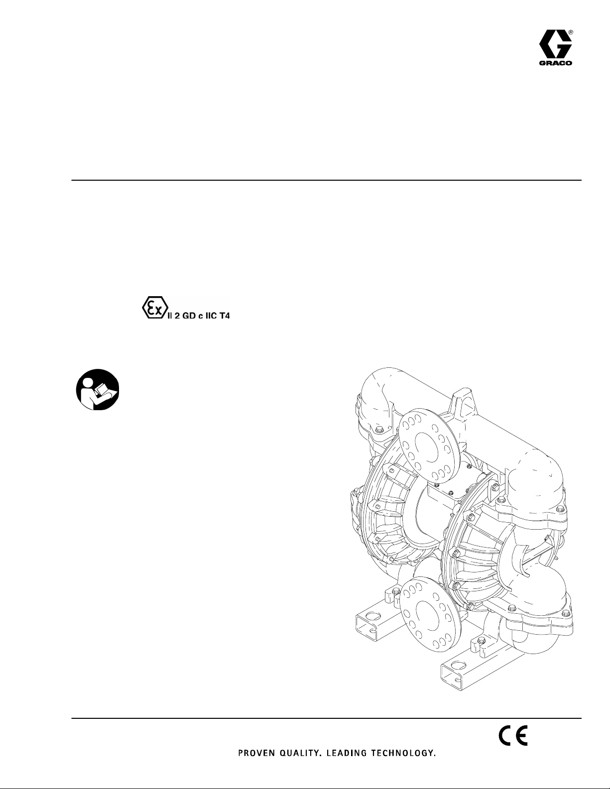
Huskyt3275 Air–Operated
Diaphragm Pump
3–inch pump for fluid transfer applications. For professional use only.
120 psi (0.8 MPa, 8 bar) Maximum Incoming Air Pressure
120 psi (0.8 MPa, 8 bar) Maximum Fluid Working Pressure
* Part No. DK3XXX
Part No. 232505 Private–Label Aluminum 3275 Pump (See page 20.)
Part No. 24D619 Private–Label Aluminum 3275 Pump (See page 20.)
* This model is certified.
US and Foreign Patents Pending
308639L
ENG
Important Safety Instructions
Read all warning and instructions in this
manual. Save these instructions.
Refer to the Pump Matrix on page 20 to
determine the Part No. of your pump.
Contents
Warnings 2. . . . . . . . . . . . . . . . . . . . . . . . . . . . . . .
Installation 4. . . . . . . . . . . . . . . . . . . . . . . . . . . . . .
Operation 9. . . . . . . . . . . . . . . . . . . . . . . . . . . . . . .
Maintenance 10. . . . . . . . . . . . . . . . . . . . . . . . . . . .
Troubleshooting 11. . . . . . . . . . . . . . . . . . . . . . . . .
Service 12. . . . . . . . . . . . . . . . . . . . . . . . . . . . . . . .
Pump Matrix 20. . . . . . . . . . . . . . . . . . . . . . . . . . . .
Repair Kit Matrix 21. . . . . . . . . . . . . . . . . . . . . . . .
Parts Drawing 22. . . . . . . . . . . . . . . . . . . . . . . . . . .
Parts Lists 23. . . . . . . . . . . . . . . . . . . . . . . . . . . . . .
Technical Data 24. . . . . . . . . . . . . . . . . . . . . . . . . .
Torque Sequence 25. . . . . . . . . . . . . . . . . . . . . . .
Dimensional Drawings 26. . . . . . . . . . . . . . . . . . .
Performance Charts 27. . . . . . . . . . . . . . . . . . . . .
Graco Standard Warranty 30. . . . . . . . . . . . . . . .
Graco Information 30. . . . . . . . . . . . . . . . . . . . . . .
06317
Page 2
Warnings
Warning Symbol
WARNING
This symbol alerts you to the possibility of serious
injury or death if you do not follow the instructions.
WARNING
EQUIPMENT MISUSE HAZARD
INSTRUCTIONS
Any misuse of the equipment or accessories, such as overpressurizing, modifying parts, using
incompatible chemicals and fluids, or using worn or damaged parts, can cause them to rupture and
result in splashing in the eyes or on the skin, other serious injury, or fire, explosion or property damage.
D This equipment is for professional use only. Observe all warnings. Read and understand all
instruction manuals, warning labels, and tags before you operate the equipment.
D Never alter or modify any part of this equipment; doing so could cause it to malfunction. Use only
genuine Graco parts and accessories.
Caution Symbol
CAUTION
This symbol alerts you to the possibility of damage to
or destruction of equipment if you do not follow the
instructions.
D Check all equipment regularly and repair or replace worn or damaged parts immediately.
D Never exceed the recommended working pressure or the maximum air inlet pressure stated on
your pump or in the Technical Data on page 24.
D Do not exceed the maximum working pressure of the lowest rated component in your system.
This equipment has a 120 psi (0.8 MPa, 8 bar) maximum working pressure at 120 psi
(0.8 MPa, 8 bar) maximum incoming air pressure.
D Be sure that all fluids and solvents used are chemically compatible with the wetted parts shown in
the Technical Data on page 24. Always read the manufacturer’s literature before you use fluid
or solvent in the pump.
D Never move or lift a pump under pressure. If dropped, the fluid section may rupture. Always
follow the Pressure Relief Procedure on page 9 before you move or lift the pump.
D The pump weighs approximately 150 lb (68 kg) If it must be moved, use the lift ring, or have two
people lift the pump by grasping the outlet manifold.
2 308639
Page 3
WARNING
HAZARDOUS FLUIDS
Improper handling of hazardous fluids or inhaling toxic vapors can cause extremely serious injury or
death from to splashing in the eyes, ingestion, or bodily contamination. Observe all the following
precautions when handling known or potentially hazardous fluids.
D Know what fluid you are pumping and its specific hazards. Take precautions to avoid a toxic fluid
spill.
D Always wear appropriate clothing and equipment, such as eye protection and breathing appara-
tus, to protect yourself.
D Store hazardous fluid in an appropriate, approved container. Dispose of it according to all Local,
State and Federal guidelines for hazardous fluids.
D Secure the fluid outlet hose tightly into the receiving container to prevent it from coming loose
and improperly draining the fluid.
D Pipe and dispose of the exhaust air safely, away from people, animals, and food handling areas.
If the diaphragm fails, the fluid is exhausted along with the air. See Air Exhaust Ventilation on
page 7.
FIRE AND EXPLOSION HAZARD
Static electricity is created by the flow of fluid through the pump and hose. If the equipment is not
properly grounded, sparking may occur. Sparks can ignite fumes from solvents and the fluid being
pumped, dust particles, and other flammable substances, whether you are pumping indoors or
outdoors, and can cause a fire or explosion and serious injury and property damage.
D To reduce the risk of static sparking, ground the pump and all other equipment used or located in
the work area. Check your local electrical code for detailed grounding instructions for your area
and type of equipment. Refer to Grounding on page 4.
D If you experience any static sparking or even a slight shock while using this equipment, stop
pumping immediately. Check the entire system for proper grounding. Do not use the system
again until the problem has been identified and corrected.
D Pipe and dispose of the exhaust air safely, away from all sources of ignition. If the diaphragm
fails, the fluid is exhausted along with the air. See Air Exhaust Ventilation on page 7.
D Do not smoke in the work area. Do not operate the equipment near a source of ignition or an
open flame, such as a pilot light.
HALOGENATED HYDROCARBON HAZARD
Never use 1,1,1–trichloroethane, methylene chloride, other halogenated hydrocarbon solvents or
fluids containing such solvents in aluminum pumps. Such use could result in a serious chemical
reaction, with the possibility of explosion, which could cause death, serious injury, and/or substantial
property damage.
Consult your fluid suppliers to ensure that the fluids used are compatible with aluminum parts.
United States Government safety standards have been adopted under the Occupational Safety and Health Act.
You should consult these standards—particularly the General Standards, Part 1910, and the Construction
Standards, Part 1926.
3308639
Page 4
Installation
General Information
D The Typical Installation shown in Fig. 2 is only a
guide for selecting and installing system
components. Contact your Graco distributor for
assistance in planning a system to suit your needs.
D Always use genuine Graco parts and accessories.
D Reference numbers and letters in parentheses refer
to the callouts in the figures and in the Parts
Drawing on page 22 and the Parts Lists on pages
23 and 24.
WARNING
HAZARDOUS FLUIDS
To reduce the risk of serious injury,
splashing in the eyes or on the skin, and
toxic fluid spills, never move or lift a
pump under pressure. If dropped, the fluid section
could rupture. Always follow the Pressure Relief
Procedure on page 9 before you move or lift the
pump.
D The pump is very heavy. If it must be moved, have
two people lift the pump by grasping the outlet
manifold (50). See the Parts Drawing on page 22.
Grounding
WARNING
ELECTRIC SHOCK HAZARD
This pump must be grounded. The
steps for grounding may differ from the
way you ground other pumps. Read and
carefully follow the grounding instructions below
before you operate the pump.
To reduce the risk of static sparking, ground the pump
and all other equipment used or located in the pumping
area. Check your local electrical code for detailed
grounding instructions for your area and type of
equipment.
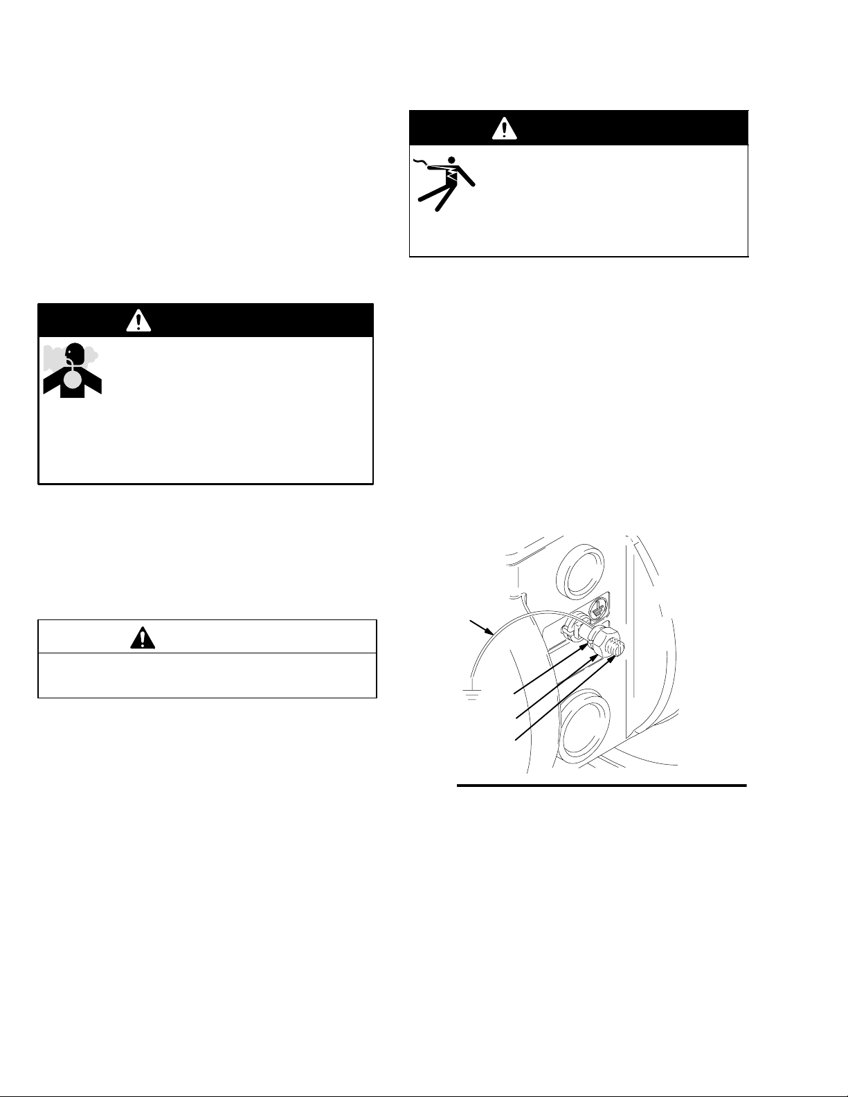
Ground all of this equipment:
D Pump: Connect a ground wire and clamp as shown
in Fig. 1. Loosen the grounding lug locknut (W)
and washer (X). Insert one end of a 12 ga (1.5
mm@) minimum ground wire (Y) into the slot in the
lug (Z), and tighten the locknut securely. Connect
the clamp end of the ground wire to a true earth
ground. To order a ground wire and clamp, order
Part No. 222011.
Use a compatible thread sealant on all male threads.
Tighten all connections firmly to avoid air or fluid leaks.
CAUTION
To avoid pump damage, do not overtighten the
fittings to the pump.
Tightening Screws Before First Use
Before using the pump for the first time, check and
retorque all external fasteners. See Torque
Sequence, page 25. After the first day of operation,
retorque the fasteners. Although pump use varies, a
general guideline is to retorque fasteners every two
months.
Y
X
W
Z
Fig. 1
D Air compressor: Follow the manufacturer’s
recommendations.
D Air and fluid hoses: Use only grounded hoses with
a maximum of 500 ft (150 m) combined hose
length to ensure grounding continuity.
D All solvent pails used when flushing: Follow the
local code. Use only metal pails, which are
conductive. Do not place the pail on a
non-conductive surface, such as paper or
cardboard, which interrupts grounding continuity.
06318
4 308639
D Fluid supply container: Follow the local code.
Page 5
Installation
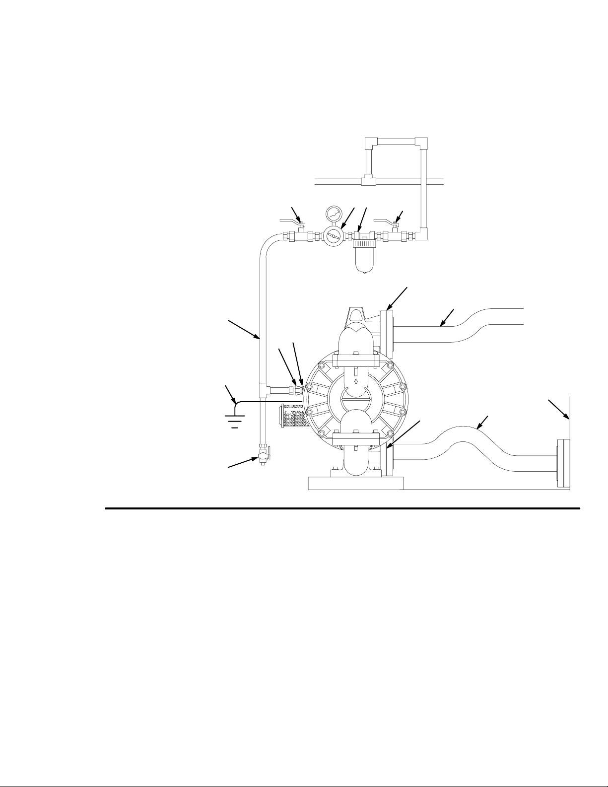
FLOOR-MOUNT TYPICAL INSTALLATION
KEY
A Air supply hose
B Bleed-type master air valve
(required for pump)
C Air regulator
D Air line quick disconnect
E Master air valve (for accessories)
F Air line filter
G Fluid suction hose
H Fluid supply
J Ball valve (for releasing collected moisture)
L Fluid outlet hose
N Air inlet port
R Fluid inlet port
S Fluid outlet port
Y Ground wire (required; see page 4
for installation instructions)
A
B
C
F
E
S
L
Fig. 2
N
D
Y
H
R
G
J
06319
5308639
Page 6
Installation
Mountings
CAUTION
The pump exhaust air may contain contaminants.
Ventilate to a remote area if contaminants could
affect your fluid supply. See Air Exhaust Ventila-
tion on page 7.
D Be sure the mounting can support the weight of the
pump, hoses, and accessories, as well as the
stress caused during operation.
D For all mountings, be sure the pump is secured with
screws through the mounting feet (58). See the
mounting feet in the Parts Drawing on page 22.
Air Line
WARNING
A bleed-type master air valve and a fluid drain
valve are required on your system.
The bleed-type master air valve relieves air
trapped between itself and the pump. Trapped air
can cause the pump to cycle unexpectedly, which
could result in serious bodily injury, including
splashing in the eyes, injury from moving parts, or
contamination from hazardous fluids.
The fluid drain valve reduces the risk of serious
bodily injury, including splashing in the eyes or on
the skin, or contamination from hazardous fluids.
Install the fluid drain valve close to the pump’s
fluid outlet to relieve pressure in the hose if the
hose becomes plugged.
2. Install a flexible air hose between the accessories
and the pump air inlet. Screw the air line fitting
into the air inlet.
3. Do not restrict the exhaust port. Excessive
exhaust restriction can cause erratic pump
operation.
Fluid Lines
WARNING
Graco always recommends that you use grounded
fluid hoses to dissipate static electricity. When
pumping non-conductive flammable fluids, grounded fluid hoses are required. See Fire and Explo-
sion Hazard on page 3.
Fluid Outlet Line
1. Attach the fluid outlet hose to the fluid outlet flange
by using a 3-in. ANSI or DIN flanged hose or pipe.
2. Install a fluid drain valve near the fluid outlet. See
the WARNING in the Air Line section at left.
Fluid Suction Line
Attach the fluid suction hose to the pump fluid inlet
flange by using a 3-in. ANSI or DIN flanged fluid
suction hose or pipe.
D If the inlet pressure to the pump is more than 25
percent of the outlet working pressure, the ball
check valves do not close fast enough, which
results in inefficient pump operation.
D At inlet fluid pressures over 15 psi (100 kPa, 1.0
bar), diaphragm life is shortened.
1. Mount the air line accessories on the wall or on a
bracket. Be sure the air line supplying the
accessories is grounded.
a. The pump speed can be controlled in one of
two ways: To control it on the air side, install
an air regulator. To control it on the fluid side,
install a fluid valve near the outlet.
b. Install a bleed-type master air valve
downstream from the air regulator, and use it
to relieve trapped air. See the WARNING,
above. Locate another bleed-type master air
valve upstream from all air line accessories,
and use it to isolate the accessories during
cleaning and repair.
c. The air line filter removes harmful dirt and
moisture from the compressed air supply.
6 308639
D The maximum suction lift is 8 ft (2.5 m) of water dry
or 28 ft (8.5 m) of water wet. For suction lifts
between 8 ft (2.5 m) and 28 ft (8.5 m) of water, it is
necessary to install a foot valve, and it is necessary
to flood the suction to prime the pump. The pump
may prime better if you reduce the inlet air pressure
until the pump is primed.
Page 7
Installation
Air Exhaust Ventilation
Changing Manifold Orientation
(See Fig. 6 on page 14)
The outlet manifold (50) and inlet manifold (53) can be
rotated to best suit your installation needs. The pump
is shipped with the inlet and outlet facing in the same
direction.
1. Remove the screws (54) from each end of the
manifold (50 or 53).
2. Turn the manifold to the desired position, and
reinstall the screws (54). Torque to 55 to 60 ft-lb
(75 to 81 NSm). See Torque Sequence, page 25.
NOTE: To ensure proper seating, visually check
that the manifold is centered on the fluid covers
(51) before you tighten the screws (54).
Fluid Pressure Relief Valve
CAUTION
Some systems may require installation of a pressure relief capability at the pump outlet to prevent
overpressurization and rupture of the pump or
hose.
Thermal expansion of fluid in the outlet line can
cause overpressurization if the fluid line is close
ended. Such overpressurization can occur when
using long fluid lines exposed to sunlight or ambient heat, or when pumping from a cool to a warm
area (for example, from an underground tank).
WARNING
TOXIC FLUID HAZARD
Be sure to read and follow the USING
HAZARDOUS FLUIDS, and FIRE OR
EXPLOSION HAZARD warnings on
page 3, before you operate this pump.
Be sure the system is properly ventilated
for your type of installation. You must
vent the exhaust to a safe place, away
from people, animals or food handling
areas when pumping flammable or
hazardous fluids.
The minimum size for the air exhaust hose is1 in.
(25.4 mm) ID x 5 ft. (1.5 m). If a longer hose is
required, use a larger diameter hose. Avoid sharp
bends or kinks in the hose.
If the diaphragm ruptures, the fluid being pumped
will be exhausted with the air. Place a container at
the end of the air exhaust line to catch fluid in case
the diaphragm ruptures.
The air exhaust port is 1 npt(f). Do not restrict the air
exhaust port. Excessive exhaust restriction can cause
erratic pump operation.
To provide a remote exhaust:
1. Remove the muffler (60) from the pump air
exhaust port.
2. Install a grounded air exhaust hose (T) and
connect the muffler (60) to the other end of the
hose. The minimum size for the air exhaust hose
is 1 in. (25.4 mm) ID x 5 ft (1.5 m). If a longer
hose is required, use a larger diameter hose.
Avoid sharp bends or kinks in the hose. See
Fig. 3.
3. Place a container (U) at the end of the air exhaust
line to catch fluid in case a diaphragm ruptures.
7308639
Page 8

Installation
VENTING EXHAUST AIR
KEY
A Air supply line
E
FC
B
B Bleed-type master air valve
(required for pump)
C Air regulator
D Air Line quick disconnect
E Master air valve (for accessories)
F Air line filter
J Ball valve (for releasing collected moisture)
P Muffler
T Grounded air exhaust hose
U Container for remote air exhaust
Fig. 3
D
A
J
T
U
60
06321
8 308639
Page 9
Operation
Pressure Relief Procedure
WARNING
To reduce the risk of serious injury, including
splashing fluid in the eyes or on the skin, follow this
procedure whenever you are instructed to relieve
pressure, when you shut off the pump, and before
you check, adjust, clean, move, or repair any
system equipment.
1. Shut off the air to the pump.
2. Open any available outbound fluid valves to relieve
fluid pressure from the pump.
3. If fluid is still in the outbound fluid lines, isolate this
fluid as follows:
a. Close the outbound fluid valves.
b. Slowly remove the fluid connections from the
pump, and have a container ready to catch
any fluid that runs out.
Flush the Pump Before First Use
The pump was tested in water. If water could
contaminate the fluid you are pumping, flush it
thoroughly with a compatible solvent. Follow the
procedure in Starting and Adjusting the Pump.
3. Place the suction tube (if used) in the fluid to be
pumped.
NOTE: If the inlet pressure to the pump is more
than 25 percent of the outlet working pressure, the
ball check valves will not close fast enough,
resulting in inefficient pump operation.
4. Place the end of the outlet hose into an
appropriate container.
5. Close the fluid drain valve.
6. With the air regulator closed, open all bleed-type
master air valves.
7. If the outlet hose has a dispensing device, hold it
open while continuing with step 8.
8. Slowly open the air regulator until the pump starts
to cycle. Allow the pump to cycle slowly until all air
is pushed out of the lines and the pump is primed.
If you are flushing, run the pump long enough to
thoroughly clean the pump and hoses, close the
air regulator, and remove the suction hose from
the solvent and place it in the fluid to be pumped.
If you are shutting down the pump, remove the
suction hose from the fluid container, run the pump
until the fluid is forced out of the system, and shut
off the air supply immediately.
If you are going to use the pump, start the pump
again, and place the suction hose in the supply
container.
Starting and Adjusting the Pump
WARNING
To reduce the risk of serious injury, splashing in
the eyes or on the skin, and toxic fluid spills,
never move or lift a pump under pressure. If the
pump is dropped, the fluid section could rupture.
Always follow the Pressure Relief Procedure
above before you move or lift the pump.
1. Be sure the pump is properly grounded. Read and
follow the instructions in Grounding on page 4.
2. Check all fittings to be sure they are tight. Be sure
to use a compatible liquid thread sealant on all
male threads.
Pump Shutdown
At the end of the work shift and before checking,
adjusting, cleaning, or repairing the system, relieve
the pressure.
WARNING
To reduce the risk of serious injury whenever you
are instructed to relieve pressure, always follow the
Pressure Relief Procedure at left.
9308639
Page 10
Maintenance
Lubrication
The air valve is designed to operate unlubricated.
If lubrication is desired, every 500 hours of operation
(or monthly), remove the hose from the pump air inlet
and add two drops of machine oil to the air inlet.
CAUTION
Do not over-lubricate the pump. Excess oil is exhausted through the muffler, which could contaminate your fluid supply or other equipment.
Flushing and Storage
Flush the pump often enough to prevent the fluid you
are pumping from drying or freezing in the pump and
damaging it. Always flush the pump and relieve the
pressure before storing it for any length of time. Use
a compatible solvent.
WARNING
Tightening Connections
Before each use, check all hoses for wear or damage,
and replace them as necessary. Check to be sure all
connections are tight and leak free. Check fasteners.
Tighten or retorque as necessary. Although pump use
varies, a general guideline is to retorque fasteners
every two months. See Torque Sequence, page 25.
Preventive Maintenance Schedule
Establish a preventive maintenance schedule, based
on the pump’s service history. This is especially
important for prevention of spills or leakage due to
diaphragm failure.
To reduce the risk of serious injury whenever you
are instructed to relieve pressure, always follow the
Pressure Relief Procedure on page 9.
10 308639
Page 11

Troubleshooting
WARNING
To reduce the risk of serious injury, including splashing fluid in the eyes or on the skin, follow the Pressure
Relief Procedure on page 9. You must do this whenever this manual instructs you to relieve pressure, when
you shut off the pump, and before checking, adjusting, cleaning, moving, or repairing any system equipment.
NOTE: Check all possible problems and causes before you disassemble the pump.
PROBLEM CAUSE SOLUTION
Pump cycles at stall or fails to hold pressure at stall.
Pump will not cycle, or cycles once and
stops.
Pump operates erratically. Suction line is clogged. Inspect; clear.
Air bubbles in fluid. Suction line is loose. Tighten.
Worn check valve balls (201), seats
(101) or o-rings (102).
Air valve is stuck or dirty. Disassemble and clean air valve. See
Check valve ball (201) severely worn
and wedged in seat (101) or manifold
(50 or 53).
Check valve ball (201) is wedged into
seat (101), due to overpressurization.
Dispensing valve is clogged. Relieve pressure and clear valve.
Sticky or leaking check valve balls
(201).
Diaphragm (301) is ruptured. Replace. See pages 15 to 17.
Restricted exhaust. Remove restriction.
Diaphragm (301) is ruptured. Replace. See pages 15 to 17.
Loose inlet manifold (53), damaged seal
between manifold and seat (101), or
damaged o-rings (101).
Replace. See page 14.
pages 12 to 13. Use filtered air.
Replace ball and seat. See page 14.
Install a pressure relief valve
(see page 7).
Clean or replace. See page 14.
Tighten manifold bolts (54), or replace
seats (101) or o-rings (102). See
page 14.
Loose diaphragm shaft bolt (14). Tighten or replace. See pages 15 to 17.
Damaged o-ring (102). Replace. See pages 15 to 17.
Fluid in exhaust air. Diaphragm (301) is ruptured. Replace. See pages 15 to 17.
Loose diaphragm shaft bolt (14). Tighten or replace. See pages 15 to 17.
Damaged o-ring (102). Replace. See pages 15 to 17.
Pump leaks air externally. Air valve cover screws (3) are loose. Tighten screws. See page 13.
Pump leaks fluid externally from ball
check valves.
Air valve gasket (20) or air cover gasket
(10) is damaged.
Loose manifolds (50 or 53), damaged
o-ring (102) between manifold and seat.
Inspect; replace. See pages 12 to 13,
18 to 19.
Tighten manifold bolts (54), or replace
o-rings (102). See page 14.
11308639
Page 12

Service
Repairing the Air Valve
Tools Required
D Torque wrench
D 7-mm or 9/32-in. socket wrench or TorxR
screwdriver T20
D Needle-nose pliers
D O-ring pick
D Lithium-base grease, Part No. 111920 (Lubriplate
630AA or equivalent)
NOTE: Air Valve Service Kit 238765 is available.
Parts included in the Air Valve Service Kit are marked
with a symbol in the Air Motor Parts List, for
example (3{). See page 23. Use all the parts in the
kit for the best results.
3. Move the main valve (6) to the center position, and
pull it out of the cavity. Using a needle-nose pliers,
pull the pilot block (16) straight up and out of the
cavity.
4. Pull the two actuator pistons (7) out of the
bearings (8). Remove the u-cup seals (9) from the
pistons. Pull the push pins (18) out of the bearings
(17). Remove the o-rings (19) from the housing
(2) with an o-ring pick.
5. Inspect the valve plate (11) in place. If damaged,
use a TorxR T20 screwdriver or 7-mm or 9/32-in.
socket wrench to remove the screws (3).
Disassembly (See Fig. 4)
1. Relieve the pressure.
WARNING
To reduce the risk of serious injury whenever you
are instructed to relieve pressure, always follow the
Pressure Relief Procedure on page 9.
2. With a 7-mm or 9/32-in. socket wrench or TorxR
T20 screwdriver, remove the screws (3), air valve
cover (5), and valve cover gasket (20).
2
3
5
16
20
6. Remove the valve plate (11) and seal (12). See
Fig. 5.
7. Inspect the bearings (8 and 17) in place. The
bearings are tapered, and, if damaged, must be
removed from the outside. See Removing and
Replacing Bearings and Air Gasket on page 18.
8. Clean all parts and inspect for wear or damage.
Replace as needed. Reassemble as explained on
page 13.
11
3
1
2
19
8
17
6
groove
18
4
6
2
Fig. 4
12 308639
06322
Apply grease to lapped
1
surfaces of 16.
2
Torque to 28 to 50 in-lb (3.2 to 5.6 NSm).
3
Install with lips facing narrow end of piston.
4
Insert narrow end first.
5 Insert wide end first.
6
Grease.
3
9
6
5
7
06323
Page 13

Service
Reassembly
For steps 1 to 3, see Fig. 5.
1. If you removed the bearings (8 and 17), install new
ones and reassemble the fluid section as
explained on page 18.
2. Grease and install the valve plate seal (12) in the
groove at the bottom of the valve cavity.
6. Grease the u-cup seals (9). Insert the actuator
pistons in the bearings (8) wide end first. Leave
the narrow end of each piston exposed in the valve
cavity.
7. Grease the lower face of the pilot block (16), and
install so its tabs snap into the grooves on the
ends of the pilot pins (16).
3. Install the valve plate (11) in the cavity with the
counter-bore facing up. Insert the screws (3) that
hold the valve plate. Using a 7-mm or 9/32-in.
socket wrench or TorxR T20 screwdriver, torque
the screws to 28 to 50 in-lb (3.2 to 5.6 NSm).
For steps 4 to 11, see Fig. 4.
4. Grease the o-rings (19), and install them in the
housing (2). Grease the push pins, and insert them
into the bearings (17) narrow end first.
5. Install a u-cup seal (9) on each actuator piston (7),
so the lips of the packings face the narrow end of
the piston.
1
1
Grease.
12
11
8. Grease the lower face of the main valve (6).
9. Install the main valve (6) so its tabs slip into the
grooves on the narrow ends of the actuator
pistons (7).
10. Slide the pilot block (16) and the main valve (6) to
one side of the valve cavity. See Fig. 4.
11. Align the valve cover o-ring (20) and cover (5) with
the holes in the center housing (2). Insert the
screws (3). Using a TorxR T20 screwdriver or
7 mm or 9/32-in. socket wrench, torque the screws
to 28 to 50 in-lb (3.2 to 5.6 NSm).
2
3
2
Fig. 5
Torque to 28 to 50 in-lb (3.2 to 5.6 NSm).
06324
13308639
Page 14

Service
Ball Check Valve Repair
Tools Required
D Torque wrench
D 15-mm socket wrench
D O-ring pick
NOTE: A Fluid Section Service Kit is available. See
the Repair Kit Matrix on page 21 to find the correct kit
for your pump. Parts included in the kit are marked
with an asterisk in the Parts Drawing on page 22, for
example (201*). Use all the parts in the kit for the best
results.
NOTE: To ensure proper seating of the balls (201),
always replace the seats (101) when you replace the
balls.
Disassembly (See Fig. 6)
1. Relieve the pressure.
WARNING
Torque to 55 to 60 ft-lb (75 to 81 NSm). See Torque
1
Sequence, page 25.
2
The ball seat is on the same side as the step for the
o-ring (102).
3
To ensure proper seating, visually check that the
manifold (50 or 53) is centered on the fluid covers
(51) before you tighten the screws (54).
54
50
1
3
201
102
To reduce the risk of serious injury whenever you
are instructed to relieve pressure, always follow the
Pressure Relief Procedure on page 9.
WARNING
Some of the pump parts and assemblies are heavy.
Use proper lifting equipment and techniques.
2. Using a 15-mm socket wrench, remove the bolts
(54) holding the outlet manifold (50) to the fluid
covers (51).
3. Remove the seats (101), balls (201), and o-rings
(102) from the fluid covers (51).
4. Remove the inlet manifold bolts (54).
5. Remove the seats (101), balls (201), and o-rings
(102) from the fluid covers (51).
Reassembly (See Fig. 6)
1. Clean all parts, and inspect for wear or damage.
Replace parts as needed.
101
54
101
53
2
51
1
201
102
2
3
2. Reassemble in the reverse order, following all
notes in Fig. 6. Be sure all parts are assembled
exactly as shown.
NOTE: To ensure proper seating, visually check
that the manifold (50 or 53) is centered on the fluid
covers (51) before you tighten the screws (54).
14 308639
Fig. 6
06325
Page 15

Service
Diaphragm Repair
Tools Required
D Torque wrench
D 15-mm socket wrench
D 15/16-in. socket wrench
D 7/8 in. open–end wrench
D O-ring pick
D Lithium-base grease, Part No. 111920 (Lubriplate
630AA or equivalent)
51
NOTE: A Fluid Section Service Kit is available. See
the Repair Kit Matrix on page 21 to find the correct kit
for your pump. Parts included in the kit are marked
with an asterisk in the Parts Drawing on page 22, for
example (201*). Use all the parts in the kit for the best
results.
Fig. 7
1
54
1
1
1
Torque to 55 to 60 ft-lb (75 to 81 NSm) in a crossing pattern.
See Torque Sequence, page 25.
51
54
1
06326
15308639
Page 16

Service
Disassembly
1. Relieve the pressure.
WARNING
To reduce the risk of serious injury whenever you
are instructed to relieve pressure, always follow the
Pressure Relief Procedure on page 9.
WARNING
Some of the pump parts and assemblies are heavy.
Use proper lifting equipment and techniques.
2. Remove the manifolds and disassemble the ball
check valves as explained in Ball Check Valve
Repair on page 14.
3. Using a 15-mm socket wrench, remove the
screws (54), and pull the fluid covers off the pump.
See Fig. 7.
For steps 4 to 9, see Fig. 8.
Reassembly (See Fig. 8)
1. Install each u-cup seal (15) so the lips face away
from the center of the pump. Lubricate the u-cup
seals.
2. Install a diaphragm assembly on one end of the
shaft (14) as follows:
a. Place a washer (63) and then a white o-ring
(64) on the diaphragm bolt (62). The o-ring
may fit very snugly on the bolt. Insert the bolt
into the fluid-side diaphragm plate (52) as
shown in Fig. 8. Grease the bolt threads.
b. Lay the diaphragm (301) into the grooves on
the fluid-side diaphragm plate (52) so that the
side marked AIR SIDE faces the center of the
pump.
For models with bolt–through PTFE
diaphragms, also install the shim (302) and
back-up diaphragm (303), as shown in Fig. 8.
Line up diaphragm tabs with tabs on air cover.
The bolts must go through the bolt–through
PTFE diaphragm.
4. Using 15/16-in. wrenches or sockets, loosen but
do not remove one of the diaphragm plate bolts
(62). (whichever one turns)
5. Remove the fluid-side plate (52), diaphragm (301),
and air-side plate (57).
For models with PTFE diaphragms, also remove
the shim (302) and back-up diaphragm (303).
6. Pull the other diaphragm assembly and the
diaphragm shaft (14) out of the center housing (2).
Hold the shaft flats with a 7/8-in. wrench, and
remove the remaining fluid-side plate (52) from the
shaft. Disassemble the remaining diaphragm
assembly.
7. Inspect the diaphragm shaft (14) for wear or
scratches. If it is damaged, inspect the bearings
(13) in place. If the bearings are damaged, see
Removing and Replacing Bearings and Air
Gasket on page 18.
8. Reach into the center housing (2) with an o-ring
pick, and hook the u-cup seals (15), then pull them
out of the housing. This can be done with the
bearings (13) in place.
9. Clean all parts and inspect for wear or damage.
Replace parts as needed.
c. Place the air-side diaphragm plate (57) and
washer (63) over the bolt. Screw the shaft
(14) onto the bolt handtight.
3. Grease the length of the shaft (14), and slide it
through the center housing (2).
4. Assemble the other diaphragm assembly to the
shaft as explained in step 2.
Step 5 is easiest if the pump is mounted vertically in a
vise.
5. Torque the bolts (62) to 100 to 120 ft-lb (136 to
163 NSm).
WARNING
Failure to properly torque the diaphragm bolts (62)
could result in a bolt failure. If a diaphragm bolt
fails, fluid is exhausted through the muffler. See
Air Exhaust Ventilation on page 7.
6. Install the fluid cover screws (54) hand tight.
Torque the screws to 55 to 60 ft-lb (75 to 81 NSm)
in a crossing pattern. See Fig. 7. See Torque
Sequence, page 25.
7. Reassemble the ball check valves and manifolds
as explained on page 14.
16 308639
Page 17

Service
Cutaway View with Diaphragms in Place Cutaway View with Diaphragms Removed
57
52
64
62
4
63
1313
1
14
15
3
2
303
3
14
63
57
302
5
2
6
1
Lips face out of housing (1).
2
Side marked AIR SIDE must face center housing (2).
3
Grease.
4
301
Torque to 100 to 120 ft-lb (136 to 163 NSm).
5
52
06327
06328
1 1
1
14
64
1
3
63
301
2
4
62
06329A
5
Used only in models with PTFE diaphragms.
6
Bolt–through PTFE diaphragms: Line up diaphragm tabs with tabs on air cover. Bolts go through the diaphragm.
Fig. 8
17308639
Page 18

Service
Removing and Replacing Bearings and Air Gasket (See Fig. 9)
Tools Required
D Torque wrench
D 13-mm socket wrench
D Bearing puller
D O-ring pick
6. Remove the air cover gaskets (10). Always
replace the gaskets with new ones.
7. Use a bearing puller to remove the diaphragm
shaft bearings (13), piston actuator bearings (8),
and push pin bearings (17). Do not remove any
bearings if they are not damaged.
D Press, or block and mallet
Disassembly
NOTE: Do not remove undamaged bearings. This
procedure is only for replacing bearings that are
damaged.
1. Relieve the pressure.
WARNING
To reduce the risk of serious injury whenever you
are instructed to relieve pressure, always follow the
Pressure Relief Procedure on page 9.
2. Remove the manifolds, and disassemble the ball
check valves as explained on page 14.
3. Remove the fluid covers and diaphragm
assemblies as explained on pages 15 and 16.
NOTE: If you are removing only the diaphragm shaft
bearing (8), skip step 4.
4. Disassemble the air valve as explained on
page 12.
5. Using a 13-mm socket wrench, remove the screws
(27) holding the air covers (1) to the center
housing (2). See Fig. 9.
Reassembly
1. Insert the bearings (8, 13, and 17) into the housing
(2), tapered end first. Using a press or a block
and mallet, press-fit each bearing so it is flush with
the surface of the housing.
2. Reassemble the air valve as explained on
page 13.
3. Install the u-cup shaft seals (15) with the lips
facing away from the bearing (13). See Fig. 8.
4. Align each new air cover gasket (10) so the push
pin (18) protruding from the center housing (2) fits
through the proper hole (H) in the gasket, as
shown in Fig. 8.
5. Align each air cover (1) so the through hole is on
the bottom, as shown in Fig. 8. Install the screws
(27) handtight. Using a 13-mm socket, torque the
screws oppositely and evenly to 19 to 21 ft-lb (26
to 28 NSm).
6. Install the diaphragm assemblies and fluid covers
as explained on page 16.
7. Reassemble the ball check valves and manifolds
as explained on page 14.
18 308639
Page 19

1
Press-fit bearings flush with surface of center housing (2).
2
Torque to 19 to 21 ft-lb (26 to 28 NSm).
Service
8
1
17
1
Detail of Bearings
Fig. 9
06330
15
1
18
H
1
2
10
2
27
through hole must
be on bottom
1
06331
19308639
Page 20

Pump Matrix
Husky 3275 Pumps, Series C
Your Model No. is marked on the pump’s serial plate. To determine the Model No. of your pump from the following
matrix, select the six digits that describe your pump, working from left to right. The first digit is always D,
designating Husky diaphragm pumps. The remaining five digits define the materials of construction.
For example, a pump with an aluminum air motor and fluid section, TPE seats, PTFE balls, and TPE diaphragms is
Model
D K 3 5 1 5. To order replacement parts, refer to the Part Lists on pages 23 and 24. The digits in the
matrix do not correspond to the reference numbers in the Parts Drawing and Parts Lists.
Diaphragm
Pump Air Motor Fluid Section – Seats Balls Diaphragms
232505* aluminum aluminum – TPE acetal TPE
D (for all pumps) K (aluminum) 3 (aluminum) – 0 (null) 0 (null) 0 (null)
– 3 (316 SST) 1 (PTFE)
– 5 (TPE) 2 (acetal) 5 (TPE)
– 6 (Santoprener) 6 (Santoprener) 6 (Santoprener)
– G (Geolastr) G (Geolastr) G (Geolastr)
P (bolt–through PTFE)
* 232505, Aluminum 3275 Pump, Series C
Model No. 232505 is a private-label aluminum 3275 pump. Other than the label, it is the same
as Model No. DK3525.
* 24D619, Aluminum 3275 Pump, Series A
Model No. 24D619 is a private-label aluminum 3275 pump. Other than the label and the parts listed below, it is the
same as Model No. DK3525.
Ref. No. 54 is Part No. 16D109 SCREW, M12 x 1.75 x 55 mm (2.17”); stainless steel. Qty: 40
20 308639
Page 21

Repair Kit Matrix
For Husky 3275 Pumps, Series C
Repair kits may be ordered separately. To repair the air valve, order the Air Valve Service Kit, Part No. 238765
(see page 23). Parts included in the Air Valve Service Kit are marked with a symbol in the Air Motor Parts List, for
example (3{).
To repair the seats, balls, and diaphragms, select the six digits that describe your pump from the following matrix,
working from left to right. The first digit is always D, the second digit is always 0 (zero), and the third digit is
always K. The remaining three digits define the materials of construction. Parts included in the kit are marked with
an asterisk in the Parts Drawing on page 22, for example (201*).
For example, if your pump has SantopreneR seats, PTFE balls, and SantopreneR diaphragms, you need to order
Repair Kit D 0 K 6 1 6. The digits in the matrix do not correspond to the reference numbers in the Parts
Drawing and Parts Lists on pages 23 and 24.
Diaphragm
Pump Air Motor Shaft O-Ring – Seats Balls Diaphragms
D (for all pumps) 0 (for all pumps) K (for all pumps) – 0 (null) 0 (null) 0 (null)
– 3 (316 SST) 1 (PTFE)
– 5 (TPE) 2 (acetal) 5 (TPE)
– 6 (SantopreneR) 6 (SantopreneR) 6 (SantopreneR)
– G (Geolastr) G (Geolastr) G (Geolastr)
P (bolt–through PTFE)
21308639
Page 22

3{
Parts Drawing
55
54
{16
61
5
20{
6
11
12{
1
23
24
2
8
13
{9
*15
10
60
19{
18
17
7
63
57
*}302
27
303}*
52
64
63
301*
62
56
54
50
201*
102*
101*
51
54
201*
102*
101*
1
* Included in Fluid Section Service Kit. See the
Repair Kit Matrix on page 21 to find the correct kit
for your pump.
{ Included in Air Valve Service Kit 238765, which
may be purchased separately. Kit includes 2 of
113554.
} Used only in models with PTFE diaphragms.
14
54
53
06316A
58
22 308639
Page 23

Parts Lists
Air Motor Parts List (Matrix Column 2)
Ref.
Digit
No. Part No. Description Qty.
K 1 190827 COVER, air; aluminum 2
2 190826 HOUSING, center;
aluminum
3{ 113554
5 190831 COVER, valve; aluminum 1
6 240222 MAIN VALVE; aluminum 1
7 190822 PISTON, actuator; acetal 2
8 190823 BEARING, piston; acetal 2
9{ 113249 SEAL, u-cup; nitroxile
10 190835 GASKET, air cover;
11 190817 PLATE, valve; SST 1
12{ 190825 SEAL, valve plate;
13 190819 BEARING, shaft; acetal 2
14 190818 SHAFT; SST 1
16{ 188614 BLOCK, pilot; acetal 1
17 190821 BEARING, pin; acetal 2
18 190820 PIN, push; SST 2
19{ 114375 PACKING, o-ring; nitrile 2
SCREW, mach, TorxR,
hex flange hd; M5 x 0.8 x
16 mm (0.63”); SST
nitrile
HDPE foam
Buna–N
1
10
2
2
1
Fluid Section Parts List (Matrix Column 3)
Ref.
No.
Digit
3 50 190830 MANIFOLD, outlet;
Y Replacement Danger and Warning labels, tags, and
cards are available at no cost.
Part No. Description Qty.
aluminum
51 190828 COVER, fluid; aluminum 2
52 191990 PLATE, fluid side;
aluminum
53 190829 MANIFOLD, inlet;
aluminum
54 113629 SCREW, M12 x 1.75 x
55 mm ( 2.17”); aluminum
55Y 290267 LABEL, warning 1
56Y 290266 LABEL, warning 1
57 192196 PLATE, air side;
aluminum
58 190906 FOOT, mounting; carbon
steel
60 111897 MUFFLER 1
61 290211 LABEL, identification 1
62 114313 SCREW, hex washer
head; 5/8–11 x 3
63 114314 WASHER, plain; 5/8” 4
64 114315 PACKING, o-ring; PTFE 2
1
2
1
40
2
2
2
20{ 113252 PACKING, o-ring;
Buna–N
23 104029 CLAMP, grounding 1
24 104582 WASHER, tab 1
27 114193 SCREW, mach, hex,
washer head
{ Included in Air Valve Service Kit 238765, which may be
purchased separately. Kit includes 2 of 113554.
* Included in Fluid Section Service Kit. See the Repair Kit
Matrix on page 21 to find the correct kit for your pump.
1
16
23308639
Page 24

Parts Lists
Seat Parts List (Matrix Column 4)
Ref.
Digit
3 101* 190840 SEAT; 316 SST 4
5 101* 190837 SEAT; TPE 4
6 101* 190836 SEAT; SantopreneR 4
G 101* 194217 SEAT; GeolastR 4
Part No. Description Qty.
No.
102* 113449 O-RING; PTFE 4
102* 113449 O-RING; PTFE 4
102* 113449 O-RING; PTFE 4
102* 113449 O-RING; PTFE 4
Ball Parts List (Matrix Column 5)
Ref.
Digit
No. Part No. Description Qty.
1 201* 113253 BALL; PTFE 4
2 201* 113266 BALL; acetal 4
6 201* 113254 BALL; SantopreneR 4
G 201* 114754 BALL; GeolastR 4
Diaphragm Parts List (Matrix Column 6)
Ref.
Digit
5 301* 190839 DIAPHRAGM; TPE 2
6 301* 190838 DIAPHRAGM;
G 301* 194218 DIAPHRAGM; GeolastR 2
P 301* 15M510 BOLT–THROUGH
* Included in Fluid Section Service Kit. See the Repair Kit
Matrix on page 21 to find the correct kit for your pump.
Part No. Description Qty.
No.
15* 113265 SEAL, u-cup; nitroxile
nitrile
SantopreneR
15* 113265 SEAL, u-cup; nitroxile
nitrile
15* 113265 SEAL, u-cup; nitroxile
nitrile
DIAPHRAGM; PTFE
302* 193414 SHIM 2
303* 190838 DIAPHRAGM, back-up;
SantopreneR
15* 113265 SEAL, u-cup; nitroxile
nitrile
2
2
2
2
2
2
2
Technical Data
Maximum fluid working pressure 120 psi . . . . . . . . . . . .
(0.8 MPa, 8 bar)
Air operating range 20 to 120 psi . . . . . . . . . . . . . . . . . .
(0.14 to 0.8 MPa, 1.4 to 8 bar)
Maximum air consumption 325 scfm. . . . . . . . . . . . . . .
Air consumption at 70 psi and100 gpm
(480 kPa, 4.8 bar and 379 lpm) 120 scfm. . . . . . . . . . . .
(1.26 m3/min)
Maximum free-flow delivery 275 gpm (1,041 lpm). . . . .
Maximum pump speed 135 cpm. . . . . . . . . . . . . . . . . . .
Gallons (liters) per cycle 2.0 (7.6). . . . . . . . . . . . . . . . . .
Maximum suction lift (water)
Dry 8 ft (2.5 m). . . . . . . . . . . . . . . . . . . . . . . . . . . . . . . .
Wet 28 ft (8.5 m). . . . . . . . . . . . . . . . . . . . . . . . . . . . . .
Maximum size pumpable solids 3/8 in. (9.4 mm). . . . .
* Sound power level measured per ISO Standard 9614–2. Sound pressure measured 1 meter from pump.
Geolastr and Santoprener are registered trademarks of the Monsanto Company.
Torx
R is a registered trademark of Camcar, Division of Textron, Inc.
24 308639
* Sound power level at 120 psi (0.8 MPa, 8 bar)
and 105 cpm 101 dBa. . . . . . . . . . . . . . . . . . . . . . . . .
* Sound pressure level at 120 psi (0.8 MPa, 8 bar)
and 105 cpm 86 dBa. . . . . . . . . . . . . . . . . . . . . . . . . .
* Sound pressure level at 50 psi (0.3 MPa, 3 bar)
and 50 cpm 76 dBa. . . . . . . . . . . . . . . . . . . . . . . . . . .
Air inlet 3/4 npt(f). . . . . . . . . . . . . . . . . . . . . . . . . . . . . . . .
Maximum operating temperature 150_ F (65_ C). . . . .
Fluid inlet 3-in. ANSI 4-bolt / DIN 8-bolt flange. . . . . . . .
Fluid outlet 3-in. ANSI 4-bolt / DIN 8-bolt flange. . . . . .
Wetted parts aluminum, PTFE, GeolastR. . . . . . . . . . .
SantopreneR, TPE, plated steel, acetal, SST
Weight approximately 150 lb (68 kg). . . . . . . . . . . . . . . .
Page 25

Torque Sequence
Always follow torque sequence when instructed to torque fasteners.
1. Left/Right Fluid Cover
Torque bolts to 55–60 ft–lb (75–81 NSm)
1
8
10
12
6
4
SIDE VIEW
3
5
11
9
7
2
2. Inlet Manifold
Torque bolts to 55–60 ft–lb (75–81 NSm)
13
17
15
3. Outlet Manifold
Torque bolts to 55–60 ft–lb (75–81 NSm)
23
19
22
TOP VIEW
21
20
24
16
14
18
BOTTOM VIEW
25308639
Page 26

Dimensional Drawings
FRONT VIEW
15.25 in.
(387.5 mm)
Eight 0.84 in.
(21.5 mm) holes (DIN)
0.185 in.
(5 mm)
7.9 in.
(200 mm) O.D.
12 in.
(305 mm)
30.5 in.
(774 mm)
SIDE VIEW
20.65 in.
(524.5 mm)
Four 0.84 in.
(21.5 mm) holes
(ANSI)
4.75 in.
(121 mm)
Fluid inlet (bottom
manifold) and fluid
outlet (top manifold):
3.25 in. (83 mm) dia. I.D.
20.3 in.
(516 mm)
24.5 in.
(622.5 mm)
4.1 in.
(104 mm)
28.6 in.
(727 mm)
PUMP MOUNTING HOLE PATTERN
13 in.
(330 mm)
Four 0.5 in.
(12.5 mm) holes
Flanges
are Flat
Faced
6.5 in.
(165 mm)
13 in.
(330 mm)
15 in.
(381 mm)
3/4 npt(f)
Air Inlet
A
4.22 in.
(117 mm)
A
16.94 in.
(430 mm)
Section
A–A
1 npt(f)
Air Exhaust
(muffler not shown)
12 in.
(305 mm)
7432A
26 308639
Page 27

140
(0.98, 9.8)
Performance Charts
Aluminum Husky 3275 Fluid Outlet Pressure
Test Conditions: Pump tested in water with inlet submerged.
120
(0.8, 8)
A
100
(0.7, 7)
B
80
(0.55, 5.5)
60
(0.41, 4.1)
40
(0.28, 2.8)
FLUID OUTLET PRESSURE––psi (MPa, bar)
20
(0.14, 1.4)
0
0 30 60 90 120 150 180 210 240 270
C
D
E
(114) (227) (568) (795)
Fluid Pressure Curves
A at 120 psi (0.8 MPa, 8 bar) air pressure
B at 100 psi (0.7 MPa, 7 bar) air pressure
C at 70 psi (0.48 MPa, 4.8 bar) air pressure
D at 40 psi (0.28 MPa, 2.8 bar) air pressure
E at 20 psi (0.14 MPa, 1.4 bar) air pressure
(341) (454) (681) (1022)
FLUID FLOW––gpm (lpm)
(908)
To find Fluid Outlet Pressure (psi/MPa/bar) at a
specific fluid flow (gpm/lpm) and operating air
pressure (psi/MPa/bar):
1. Locate fluid flow rate along bottom of chart.
2. Follow vertical line up to intersection with selected
fluid outlet pressure curve.
3. Follow left to scale to read fluid outlet pressure.
To calculate Pressure Head in feet at a specific fluid outlet
pressure (psi):
pressure head, feet = (psi * 2.31) / specific gravity of fluid
To calculate Pressure Head in meters at a specific fluid outlet
pressure (MPa):
pressure head, meters = (MPa * 102) / specific gravity of fluid
To calculate Pressure Head in meters at a specific fluid outlet
pressure (bar):
pressure head, meters = (bar * 10.2) / specific gravity of fluid
27308639
Page 28

350
(9.8)
300
(8.4)
250
(7.0)
200
(5.6)
Performance Charts
Aluminum Husky 3275 Air Consumption
Test Conditions: Pump tested in water with inlet submerged.
Air Consumption Curves
A at 120 psi (0.8 MPa, 8 bar) air pressure
B at 100 psi (0.7 MPa, 7 bar) air pressure
C at 70 psi (0.48 MPa, 4.8 bar) air pressure
D at 40 psi (0.28 MPa, 2.8 bar) air pressure
E at 20 psi (0.14 MPa, 1.4 bar) air pressure
A
150
(4.2)
100
(2.8)
AIR CONSUMPTION––scfm (cubic meters/min)
50
(1.4)
0
0 30 60 90 120 150 180 210 240 270
(114) (227) (568) (795)
To find Pump Air Consumption (scfm or m#/min) at a
specific fluid flow (gpm/lpm) and air pressure
(psi/MPa/bar):
1. Locate fluid flow rate along bottom of chart.
2. Read vertical line up to intersection with selected air
consumption curve.
3. Follow left to scale to read air consumption.
(341) (454) (681) (1022)
B
C
D
E
(908)
FLUID FLOW––gpm (lpm)
28 308639
Page 29

Notes
29308639
Page 30

Graco Warranties
Graco Standard Husky Pump Warranty
Graco warrants all equipment manufactured by Graco and bearing its name to be free from defects in material and workmanship on the
date of sale to the original purchaser for use. With the exception of any special, extended, or limited warranty published by Graco,
Graco will, for a period of five years from the date of sale, repair or replace any part of the equipment determined by Graco to be
defective. This warranty applies only when the equipment is installed, operated and maintained in accordance with Graco’s written
recommendations.
This warranty does not cover, and Graco shall not be liable for general wear and tear, or any malfunction, damage or wear caused by
faulty installation, misapplication, abrasion, corrosion, inadequate or improper maintenance, negligence, accident, tampering, or
substitution of non-Graco component parts. Nor shall Graco be liable for malfunction, damage or wear caused by the incompatibility of
Graco equipment with structures, accessories, equipment or materials not supplied by Graco, or the improper design, manufacture,
installation, operation or maintenance of structures, accessories, equipment or materials not supplied by Graco.
This warranty is conditioned upon the prepaid return of the equipment claimed to be defective to an authorized Graco distributor for
verification of the claimed defect. If the claimed defect is verified, Graco will repair or replace free of charge any defective parts. The
equipment will be returned to the original purchaser transportation prepaid. If inspection of the equipment does not disclose any defect
in material or workmanship, repairs will be made at a reasonable charge, which charges may include the costs of parts, labor, and
transportation.
THIS WARRANTY IS EXCLUSIVE, AND IS IN LIEU OF ANY OTHER WARRANTIES, EXPRESS OR IMPLIED, INCLUDING BUT
NOT LIMITED TO WARRANTY OF MERCHANTABILITY OR WARRANTY OF FITNESS FOR A PARTICULAR PURPOSE.
Graco’s sole obligation and buyer’s sole remedy for any breach of warranty shall be as set forth above. The buyer agrees that no other
remedy (including, but not limited to, incidental or consequential damages for lost profits, lost sales, injury to person or property, or any
other incidental or consequential loss) shall be available. Any action for breach of warranty must be brought within six years of the date
of sale.
Graco makes no warranty, and disclaims all implied warranties of merchantability and fitness for a particular purpose in connection
with accessories, equipment, materials or components sold but not manufactured by Graco. These items sold, but not manufactured
by Graco (such as electric motors, switches, hose, etc.), are subject to the warranty, if any, of their manufacturer. Graco will provide
purchaser with reasonable assistance in making any claim for breach of these warranties.
In no event will Graco be liable for indirect, incidental, special or consequential damages resulting from Graco supplying equipment
hereunder, or the furnishing, performance, or use of any products or other goods sold hereto, whether due to a breach of contract,
breach of warranty, the negligence of Graco, or otherwise.
FOR GRACO CANADA CUSTOMERS
The parties acknowledge that they have required that the present document, as well as all documents, notices and legal proceedings
entered into, given or instituted pursuant hereto or relating directly or indirectly hereto, be drawn up in English. Les parties
reconnaissent avoir convenu que la rédaction du présente document sera en Anglais, ainsi que tous documents, avis et procédures
judiciaires exécutés, donnés ou intentés à la suite de ou en rapport, directement ou indirectement, avec les procedures concernées.
Extended Product Warranty
Graco warrants all Husky 205, 307, 515, 716, 1040, 1590, 2150, and 3275 air valve center sections to be free from defects in material
and workmanship for a period of fifteen years from date installed in service by the original purchaser. Normal wear of items such as
packings or seals are not considered to be defects in material and workmanship.
Five years Graco will provide parts and labor.
Six to Fifteen years Graco will replace defective parts only.
Graco Information
For the latest information about Graco products, visit www.graco.com.
TO PLACE AN ORDER, contact your Graco distributor, or call one of the following numbers
to identify the distributor closest to you:
1–800–367–4023 Toll Free, 612–623–6921, 612–378–3505 Fax
All written and visual data contained in this document reflects the latest product information available at the time of publication.
Graco reserves the right to make changes at any time without notice.
Original instructions. This manual contains English. MM 308639
International Offices: Belgium, Korea, China, Japan
GRACO INC.ąP.O. BOX 1441ąMINNEAPOLIS, MNą55440-1441
Graco Headquarters: Minneapolis
Copyright 2002, Graco Inc. is registered to ISO 9001
www.graco.com
Revised 03/2010
30 308639
 Loading...