

Page 1
Instructions–Parts List
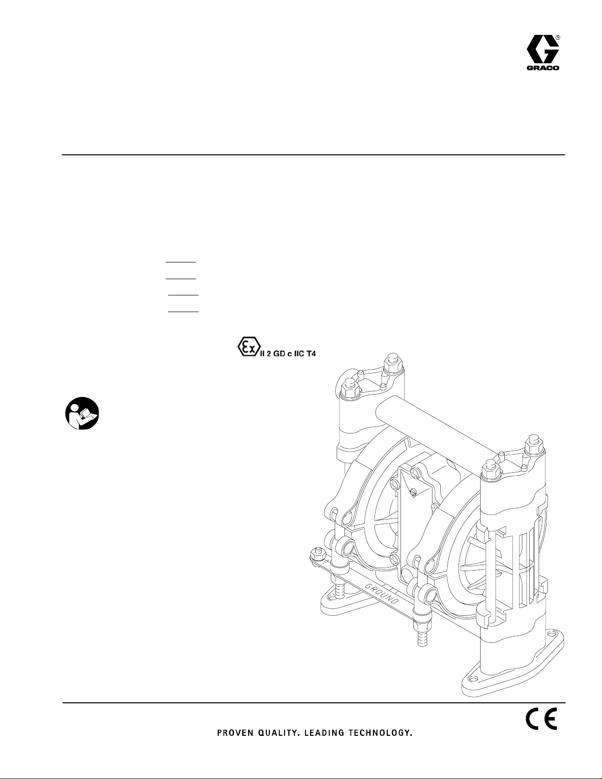
ACETAL AND POLYPROPYLENE
Husky™ 307 Air–Operated
308553ZAC
Diaphragm Pumps
For fluid transfer applications. For professional use only.
Only pumps with acetal fluid sections are approved for use in European
explosive atmosphere locations.
100 psi (0.7 MPa, 7 bar) Maximum Fluid Working Pressure
100 psi (0.7 MPa, 7 bar) Maximum Air Input Pressure
*Model No. D31 Acetal Pumps**, Series F
*Model No. D32 Polypropylene Pumps, Series F
*Model No. D3A
*Model No. D3B Polypropylene BSPT Pumps, Series F
* To determine the Model No. for your pump and for additional models, refer to the Pump Matrix
on page 26.
Acetal BSPT Pumps**, Series F
EN
** Pumps with Acetal fluid sections are certified.
Important Safety Instructions
Read all warnings and instructions in this manual.
Save these instructions.
01428B
Page 2
Table of Contents
Warnings 2. . . . . . . . . . . . . . . . . . . . . . . . . . . . . . . . . . . . . .
Installation 4. . . . . . . . . . . . . . . . . . . . . . . . . . . . . . . . . . . . .
Operation 11. . . . . . . . . . . . . . . . . . . . . . . . . . . . . . . . . . . .
Troubleshooting 12. . . . . . . . . . . . . . . . . . . . . . . . . . . . . . .
Maintenance 14. . . . . . . . . . . . . . . . . . . . . . . . . . . . . . . . . .
Service
Replacing the Air Valve 16. . . . . . . . . . . . . . . . . . . . . .
Repairing the Air Valve 18. . . . . . . . . . . . . . . . . . . . . .
Ball Check Valves 21. . . . . . . . . . . . . . . . . . . . . . . . . .
Diaphragm Repair 23. . . . . . . . . . . . . . . . . . . . . . . . . .
Pump Matrix 26. . . . . . . . . . . . . . . . . . . . . . . . . . . . . . . . . .
Additional Diaphragm Pumps 26. . . . . . . . . . . . . . . . . . .
Repair Kit Matrix 27. . . . . . . . . . . . . . . . . . . . . . . . . . . . . .
Parts 28. . . . . . . . . . . . . . . . . . . . . . . . . . . . . . . . . . . . . . . .
Torque Sequence 32. . . . . . . . . . . . . . . . . . . . . . . . . . . . .
Technical Data and Performance Charts 33. . . . . . . . . .
Dimensions 35. . . . . . . . . . . . . . . . . . . . . . . . . . . . . . . . . . .
Graco Warranties 36. . . . . . . . . . . . . . . . . . . . . . . . . . . . .
Graco Information 36. . . . . . . . . . . . . . . . . . . . . . . . . . . . .
Symbols
Warning Symbol
WARNING
This symbol alerts you to the possibility of serious
injury or death if you do not follow the instructions.
Caution Symbol
CAUTION
This symbol alerts you to the possibility of damage to
or destruction of equipment if you do not follow the
instructions.
INSTRUCTIONS
WARNING
WARNING
EQUIPMENT MISUSE HAZARD
Equipment misuse can cause the equipment to rupture or malfunction and result in serious injury.
D This equipment is for professional use only.
D Read all instruction manuals, tags, and labels before operating the equipment.
D Use the equipment only for its intended purpose. If you are not sure, call your Graco distributor.
D Do not alter or modify this equipment. Use only genuine Graco parts and accessories.
D Check equipment daily. Repair or replace worn or damaged parts immediately.
D Do not exceed the maximum working pressure of the lowest rated component in your system.
This equipment has a 100 psi (0.7 MPa, 7 bar) maximum working pressure at 100 psi
(0.7 MPa, 7 bar) maximum incoming air pressure.
D Use fluids and solvents which are compatible with the equipment wetted parts. Refer to the
Technical Data section of all equipment manuals. Read the fluid and solvent manufacturer’s
warnings.
D Do not kink or overbend hoses or use hoses to pull equipment.
2 308553
D Route hoses away from traffic areas, sharp edges, moving parts, and hot surfaces. Do not
expose Graco hoses to temperatures above 82_ C (180_ F) or below –40_ C (–40_ F).
D Do not lift pressurized equipment.
D Comply with all applicable local, state, and national fire, electrical, and safety regulations.
Page 3
WARNING
WARNING
TOXIC FLUID HAZARD
Hazardous fluid or toxic fumes can cause serious injury or death if splashed in the eyes or on the
skin, inhaled, or swallowed.
D Know the specific hazards of the fluid you are using.
D Store hazardous fluid in an approved container. Dispose of hazardous fluid according to all local,
state and national guidelines.
D Always wear protective eyewear, gloves, clothing and respirator as recommended by the fluid
and solvent manufacturer.
D Pipe and dispose of the exhaust air safely, away from people, animals, and food handling areas.
If the diaphragm fails, the fluid is exhausted along with the air. See Air Exhaust Ventilation on
page 10.
D To pump acids, always use a polypropylene pump. Take precautions to avoid acid or acid fumes
from contacting the pump housing exterior. Stainless steel parts will be damaged by exposure to
acid spills and fumes. Never use an acetal pump to pump acids.
FIRE AND EXPLOSION HAZARD
Improper grounding, poor ventilation, open flames or sparks can cause a hazardous condition and
result in a fire or explosion and serious injury.
D Ground the equipment. Refer to Grounding on page 5.
D Never use a polypropylene pump with non-conductive flammable fluids as specified by your local
fire protection code. Refer to Grounding on page 5 for additional information. Consult your fluid
supplier to determine the conductivity or resistivity of your fluid.
D If there is any static sparking or you feel an electric shock while using this equipment, stop
pumping immediately. Do not use the equipment until you identify and correct the problem.
D Provide fresh air ventilation to avoid the buildup of flammable fumes from solvents or the fluid
being pumped.
D Pipe and dispose of the exhaust air safely, away from all sources of ignition. If the diaphragm
fails, the fluid is exhausted along with the air. See Air Exhaust Ventilation on page 10.
D Keep the work area free of debris, including solvent, rags, and gasoline.
D Electrically disconnect all equipment in the work area.
D Extinguish all open flames or pilot lights in the work area.
D Do not smoke in the work area.
D Do not turn on or off any light switch in the work area while operating or if fumes are present.
D Do not operate a gasoline engine in the work area.
D Keep a fire extinguisher in the work area.
308553 3
Page 4
Installation
General Information
D The Typical Installations in Fig. 4 to Fig. 7 are only
guides for selecting and installing system compo-
nents. Contact your Graco distributor for assistance
in planning a system to suit your needs.
D Always use Genuine Graco Parts and Accessories,
available from your Graco distributor. Refer to the
Product Data Sheet for the pump, Form No.
305528 (acetal pumps) or 305543 (polypropylene
pumps). If you supply your own accessories, be
sure they are adequately sized and pressure rated
for your system.
D Use a compatible, liquid thread sealant or PTFE
tape on all male threads. Tighten all connections
firmly to avoid air or fluid leaks. Do not over-
tighten plastic threads.
D Reference numbers and letters in parentheses refer
to the callouts in the Figures and the parts lists on
pages 28 to 29.
CAUTION
Safe Operating Temperature
Minimum: 40_F (4.4_C); Maximum: 150_F (66_C).
Operating outside these temperature limits will
adversely affect the strength of the pump housing.
Certain chemicals may further reduce the operating temperature range. Consult engineering guides
for chemical compatibilities and temperature limits,
or contact your Graco distributor.
Tightening Threaded Fasteners Before
First Use
Before using the pump for the first time, check and
retorque all external fasteners. See Torque Se-
quence, page 32. After the first day of operation,
retorque the fasteners. Although pump use varies, a
general guideline is to retorque fasteners every two
months.
Mountings
D Be sure the mounting can support the weight of the
pump, hoses, and accessories, as well as the
stress caused during operation.
WARNING
TOXIC FLUID HAZARD
Hazardous fluid or toxic fumes can
cause serious injury or death if splashed
in the eyes or on the skin, inhaled, or
swallowed.
1. Read TOXIC FLUID HAZARD on page 3.
2. Use fluids and solvents which are compatible
with the equipment wetted parts. Refer to the
Technical Data section of all equipment manuals. Read the fluid and solvent manufacturer’s
warnings.
D The Husky 307 Pump can be used in a variety of
installations, some of which are shown in
Fig. 4 to Fig. 7. Kits are available to adapt your
pump to your system. Refer to the Product Data
Sheet for the pump, Form No. 305528 (acetal
pumps) or 305543 (polypropylene pumps).
D For all other mountings, be sure the pump is ade-
quately secured.
Dual Manifolds
Dual manifold kits are available to enable you to pump
two fluids simultaneously, or to mix two fluids in the
pump. Order Part No. 237211 for acetal pumps and
Part No. 237210 for polypropylene pumps.
4 308553
Page 5
Installation
Grounding
WARNING
FIRE AND EXPLOSION HAZARD
This pump must be grounded. Before
operating the pump, ground the system
as explained at right. Also read the sec-
tion FIRE AND EXPLOSION HAZARD on page
3.
The acetal pump contains stainless steel fibers,
which makes the wetted parts conductive.
Attaching the ground wire to the grounding strip
grounds the air motor and the wetted parts.
The polypropylene pump is not conductive.
When pumping conductive flammable fluids,
always ground the entire fluid system by making
sure the fluid system has an electrical path to a
true earth ground (see Fig. 4 through Fig. 7).
Never use a polypropylene pump with
non-conductive flammable fluids as specified by
your local fire protection code.
Ground all of this equipment:
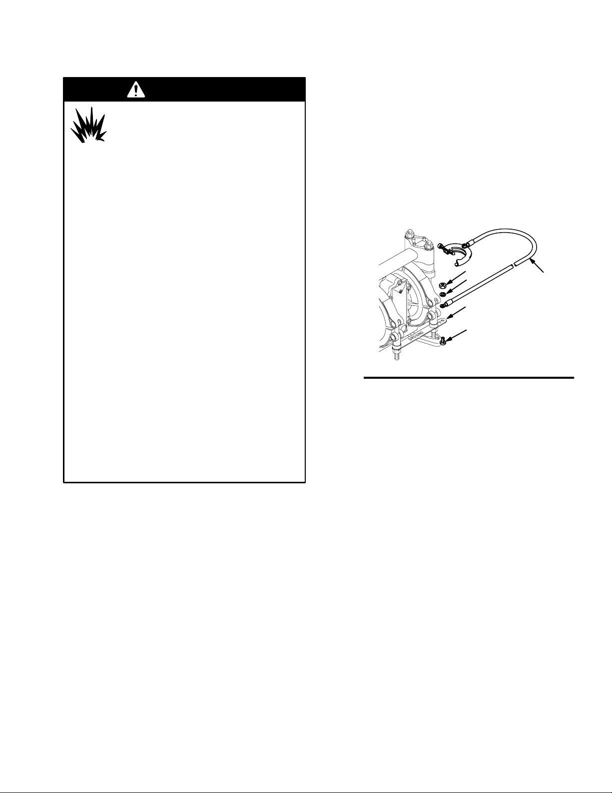
D Pump: Attach a ground wire (Y) to the grounding
strip (112) with the screw (28), lockwasher (29) and
nut (27), as shown in Fig. 1. Connect the clamp end
of the ground wire to a true earth ground. Order
Part No. 222011 Ground Wire and Clamp.
NOTE: When pumping conductive flammable fluids
with a polypropylene pump, always ground the fluid
system. See the WARNING at left. Fig. 4 through
Fig. 7 show recommended methods of grounding
flammable fluid containers during filling.
27
29
112
28
Y
US Code (NFPA 77 Static Electricity) recommends
a conductivity greater than 50 x 10
ter (mhos/meter) over your operating temperature
range to reduce the hazard of fire. Consult your
fluid supplier to determine the conductivity or
resistivity of your fluid. The resistivity must be less
than 2 x 10¹² ohm-centimeters.
To reduce the risk of static sparking, ground the pump
and all other equipment used or located in the pumping
area. Check your local electrical code for detailed
grounding instructions for your area and type of equipment.
–12
Siemans/me-
Fig. 1
D Air and fluid hoses: Use only electrically conductive
hoses.
D Air compressor: Follow the manufacturer’s recom-
mendations.
D Solvent pails used when flushing: Follow your local
code. Use only metal pails, which are conductive.
Do not place the pail on a non-conductive surface,
such as paper or cardboard, which interrupts the
grounding continuity.
D Fluid supply container: Follow your local code.
01432B
308553 5
Page 6
Installation
Air Line
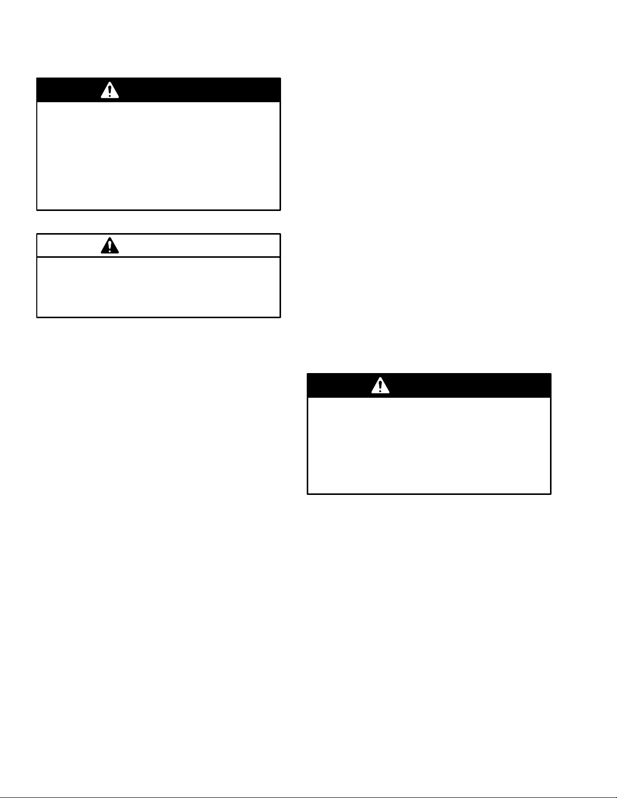
WARNING
A bleed-type master air valve (B) is required in
your system to relieve air trapped between this
valve and the pump. See Fig. 4 to Fig. 7. Trapped
air can cause the pump to cycle unexpectedly,
which could result in serious injury, including
splashing in the eyes or on the skin, injury from
moving parts, or contamination from hazardous
fluids.
CAUTION
The pump exhaust air may contain contaminants.
Ventilate to a remote area if the contaminants
could affect your fluid supply. See Air Exhaust
Ventilation on page 10.
1. Install the air line accessories as shown in Fig. 4 to
Fig. 7. Mount these accessories on the wall or on
a bracket. Be sure the air line supplying the accessories is grounded.
a. The fluid pressure can be controlled in either
of two ways. To control it on the air side, install
an air regulator (H). To control it on the fluid
side, install a fluid regulator (M) near the pump
fluid outlet (see Fig. 5).
b. Locate one bleed-type master air valve (B)
close to the pump and use it to relieve trapped
air. See the WARNING above. Locate the
other master air valve (E) upstream from all air
line accessories and use it to isolate them
during cleaning and repair.
c. The air line filter (F) removes harmful dirt and
moisture from the compressed air supply.
Fluid Suction Line
D If using a conductive (acetal) pump, use conductive
hoses. If using a non-conductive (polypropylene)
pump, ground the fluid system. See Grounding on
page 5.
D The pump fluid inlet is 3/8 npt(f). See Fig. 2.
Screw the fluid fitting into the pump inlet snugly.
Use a compatible liquid thread sealant or PTFE
tape on connections to prevent air from getting into
material line.
D At inlet fluid pressures greater than 15 psi (0.1
MPa,1 bar), diaphragm life will be shortened.
D See the Technical Data on pages 33 and 34 for
maximum suction lift and flow rate loss at various
lift distances.
Fluid Outlet Line
WARNING
A fluid drain valve (J) is required in your system to
relieve pressure in the hose if it is plugged. See
Fig. 4 to Fig. 7. The drain valve reduces the risk of
serious injury, including splashing in the eyes or on
the skin, or contamination from hazardous fluids
when relieving pressure. Install the valve close to
the pump fluid outlet.
D Use electrically conductive fluid hoses (N). The
pump fluid outlet is 3/8 npt(f). See Fig. 2. Screw the
fluid fitting into the pump outlet snugly.
2. Install an electrically conductive, flexible air hose
(C) between the accessories and the 1/4 npt(f)
pump air inlet (see Fig. 2). Use a minimum 1/4”
(6.3 mm) ID air hose. Screw an air line quick
disconnect coupler (D) onto the end of the air hose
(C), and screw the mating fitting into the pump air
inlet snugly. Do not connect the coupler (D) to the
fitting yet.
6 308553
D Install a fluid regulator (M) at the pump fluid outlet
to control fluid pressure, if desired (see Fig. 5). See
Air Line, step 1a, for another method of controlling
pressure.
D Install a fluid drain valve (J) near the fluid outlet.
See the WARNING above.
Page 7
Installation
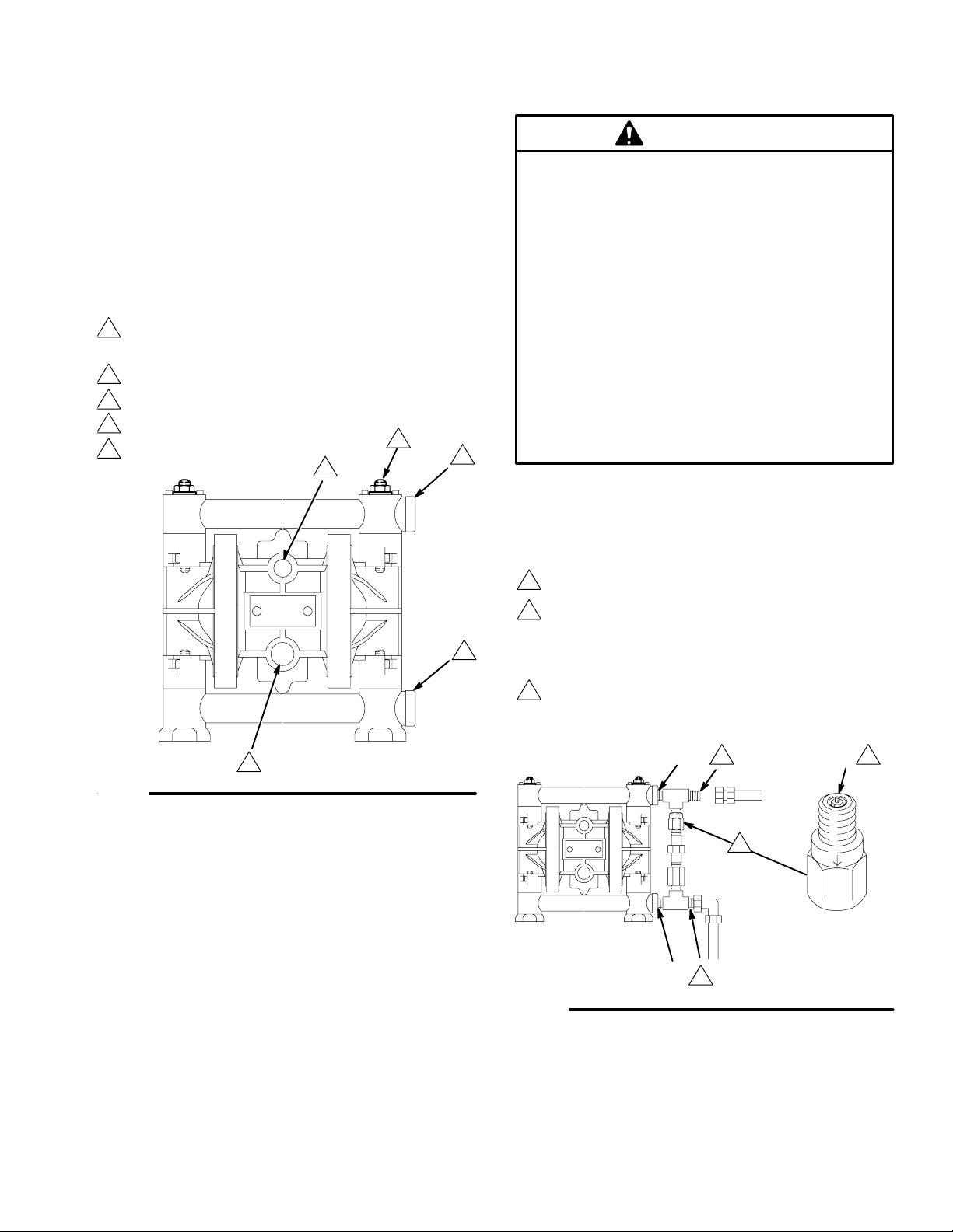
Changing the Orientation of the Fluid Inlet
and Outlet Ports
The pump is shipped with the fluid inlet and outlet
ports facing the same direction. See Fig. 2. If desired,
the direction of one or both ports can be changed.
Remove the manifold(s) from the pump as explained in
steps 1, 2, and 4 on page 21. Reattach with the port
facing the desired direction. See Torque Sequence,
page 32. Do not over-torque.
Acetal Pump Shown
Apply thread lube, and torque to 50 to 60 in-lb
1
(5.6 to 6.8 N-m). See Torque Sequence, page
32. Do not over-torque.
2
1/4 npt(f) air inlet
3
3/8 npt(f) fluid inlet
4
3/8 npt(f) fluid outlet
5
3/8 npt(f) air exhaust port
2
1
4
Fluid Pressure Relief Valve
CAUTION
Some systems may require installation of a pressure relief valve at the pump outlet to prevent
overpressurization and rupture of the pump or
hose. See Fig. 3.
Thermal expansion of fluid in the outlet line can
cause overpressurization. This can occur when
using long fluid lines exposed to sunlight or ambient heat, or when pumping from a cool to a warm
area (for example, from an underground tank).
Overpressurization can also occur if the Husky
pump is being used to feed fluid to a piston pump,
and the intake valve of the piston pump does not
close, causing fluid to back up in the outlet line.
KEY
A 3/8 npt(f) fluid inlet port
B 3/8 npt(f) fluid outlet port
C Pressure relief valve
Part No. 112119 (stainless steel)
Fig. 2
1
Install valve between fluid inlet and outlet ports.
2
Connect fluid inlet line here. Use a compatible liquid thread sealant or PTFE tape on
3
connection to prevent air from getting into
the material line.
3
Connect fluid outlet line here.
B 1
5
01459B
3
1
A
2
Fig. 3
C
01539B
308553 7
Page 8
Installation
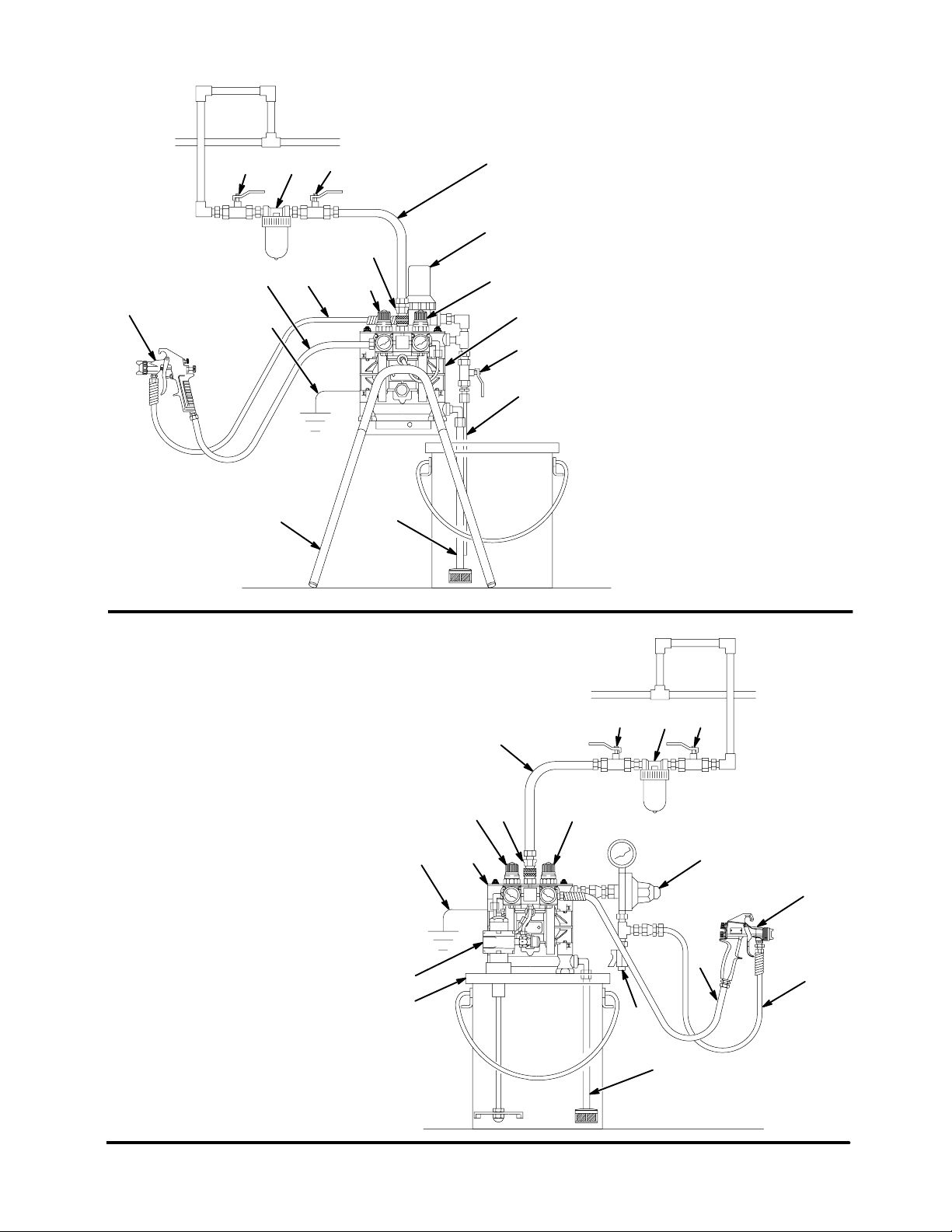
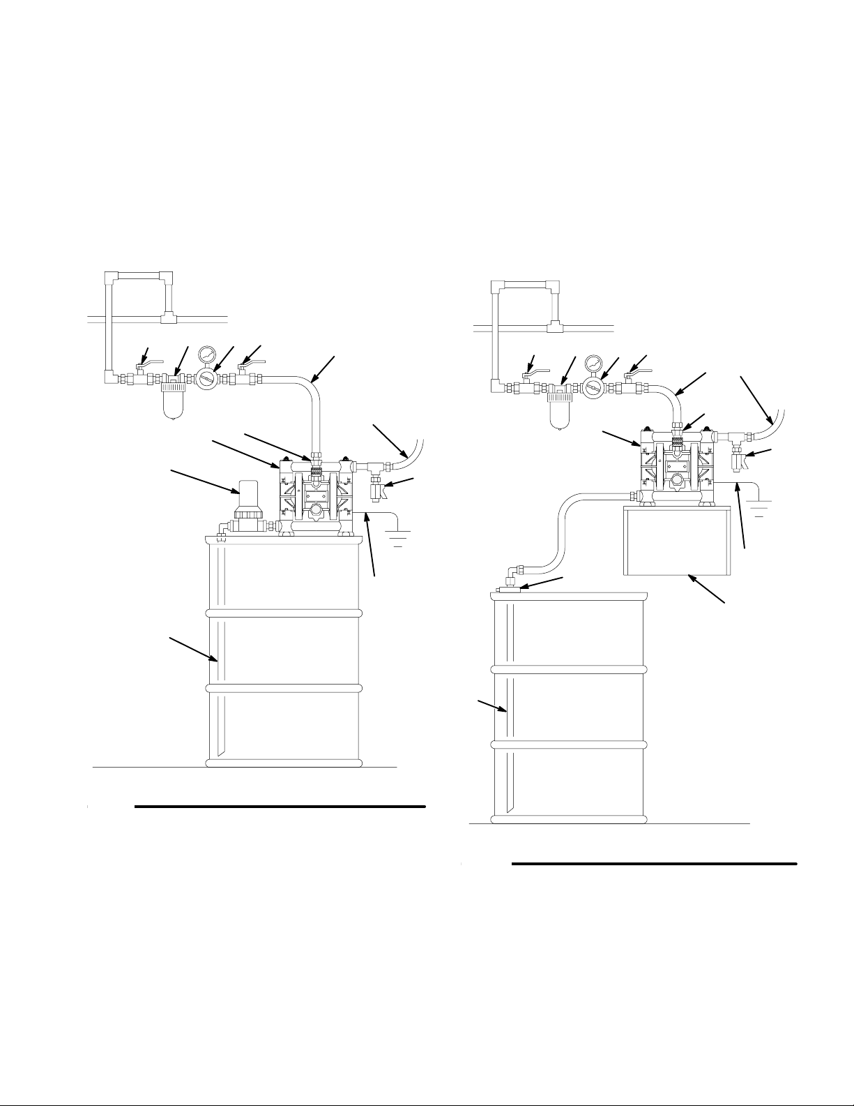
STAND-MOUNTED AIR SPRAY INSTALLATION
KEY
F BE
C
M
D
NP
R
Y
G
H
A
J
K
A Husky 307 Pump
B Bleed-Type Master Air Valve
(required for pump)
C Air Supply Hose
D Air Line Quick Disconnect
E Master Air Valve (for accessories)
F Air Line Filter
G Gun Air Regulator
H Pump Air Regulator
J Fluid Drain Valve (required)
K Fluid Recirculation Line
L Fluid Suction Line
M Surge Tank and Filter
N Fluid Supply Hose
P Gun Air Supply Hose
R Air Spray Gun
S Floor Stand
Y Ground Wire (required; see page 5
for installation instructions)
S
L
Fig. 4
PAIL-MOUNTED HVLP AIR SPRAY INSTALLATION
KEY
A Husky 307 Pump
B Bleed-Type Master Air Valve
(required for pump)
C Air Supply Line
D Air Line Quick Disconnect
E Master Air Valve (for accessories)
F Air Line Filter
G Gun Air Regulator
H Pump Air Regulator
J Fluid Drain Valve (required)
K Agitator
L Fluid Suction Line
M Fluid Regulator
N Fluid Supply Hose
P Gun Air Supply Hose
R HVLP Air Spray Gun
S Pail Cover
Y Ground Wire (required; see page 5
for installation instructions)
01433B
FBE
C
H
DG
Y
A
M
R
P
K
N
S
J
Fig. 5
8 308553
L
01434B
Page 9
Installation
BUNG-MOUNT TRANSFER INSTALLATION
KEY
A Husky 307 Pump
B Bleed-Type Master Air Valve
(required for pump)
C Air Supply Line
D Air Line Quick Disconnect
E Master Air Valve (for accessories)
F Air Line Filter
H Pump Air Regulator
J Fluid Drain Valve (required)
L Fluid Suction Line
M Fluid Inlet Filter
N Fluid Supply Hose
Y Ground Wire (required; see page 5
for installation instructions)
FHBE
D
A
C
N
M
WALL-MOUNT TRANSFER INSTALLATION
KEY
A Husky 307 Pump
B Bleed-Type Master Air Valve
(required for pump)
C Air Supply Line
D Air Line Quick Disconnect
E Master Air Valve (for accessories)
F Air Line Filter
H Pump Air Regulator
J Fluid Drain Valve (required)
L Fluid Suction Line
N Fluid Supply Hose
S Wall Bracket
T Bung Adapter
Y Ground Wire (required; see page 5
for installation instructions)
FHBE
NC
D
A
J
J
Fig. 6
Y
T
Y
S
L
L
01444B
Fig. 7
01457B
308553 9
Page 10
Installation
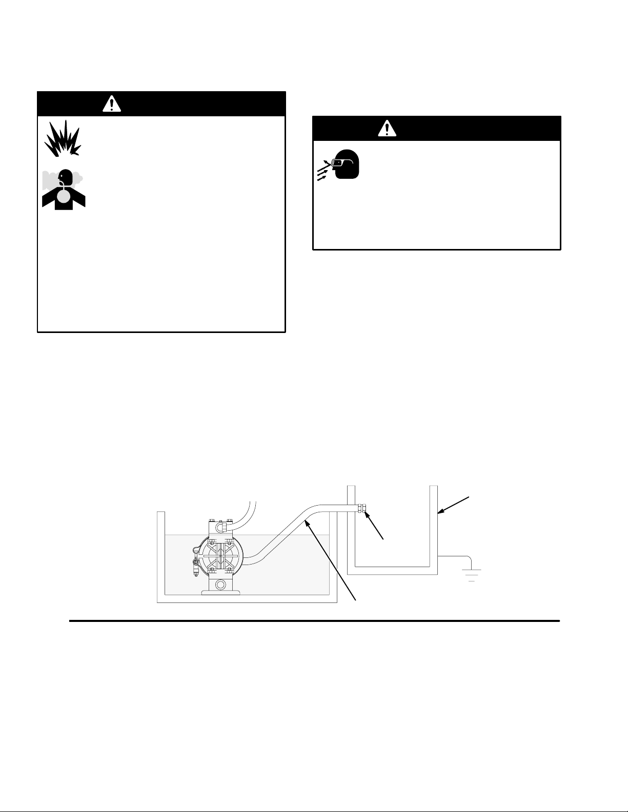
Air Exhaust Ventilation
WARNING
FIRE AND EXPLOSION HAZARD
Be sure to read FIRE OR EXPLOSION
HAZARD and TOXIC FLUID HAZARD
on page 3, before operating this pump.
Be sure the system is properly ventilated
for your type of installation. You must
vent the exhaust to a safe place, away
from people, animals, food handling areas, and all
sources of ignition when pumping flammable or
hazardous fluids.
Diaphragm failure will cause the fluid being
pumped to exhaust with the air. Place an appropriate container at the end of the air exhaust line to
catch the fluid. See Fig. 8.
The air exhaust port is 3/8 npt(f). Do not restrict the air
exhaust port. Excessive exhaust restriction can cause
erratic pump operation.
To exhaust to a remote location:
1. Remove the muffler (11) from the pump air
exhaust port.
WARNING
PRESSURIZED EQUIPMENT HAZARD
To reduce the risk of serious eye injury
from ice particles, never operate the
pump with the air exhaust port open. Ice
may form during pump operation, and ice particles
will be ejected from the port along with the exhaust
air. If the muffler (11) is removed, always connect
an air exhaust hose to the exhaust port.
2. Install an electrically conductive air exhaust hose
(X) and connect the muffler to the other end of the
hose. The minimum size for the air exhaust hose
is 3/8 in. (10 mm) ID. If a hose longer than 15 ft
(4.57 m) is required, use a larger diameter hose.
Avoid sharp bends or kinks in the hose.
3. Place a container (Z) at the end of the air exhaust
line to catch fluid in case a diaphragm ruptures. If
the fluid is flammable, ground the container. See
Fig. 8.
Fig. 8
VENTING EXHAUST AIR (Submerged Installation Shown)
See Fig. 4 for accessories
In a submerged installation (as shown), all wetted and non-wetted
pump parts must be compatible with the fluid being pumped.
11
X
Z
01445A
10 308553
Page 11
Operation
Pressure Relief Procedure
WARNING
PRESSURIZED EQUIPMENT HAZARD
The system pressure must be manually relieved to
prevent the system from starting or spraying accidentally. To reduce the risk of an injury from accidental spray from the gun, splashing fluid, or moving parts, follow the Pressure Relief Procedure
whenever you
D Are instructed to relieve the pressure
D Stop spraying
D Check or service any of the system equipment
D Install or clean the spray tips
1. Shut off the air to the pump.
2. Open the dispensing valve, if used.
3. Open the fluid drain valve to relieve all fluid pressure, having a container ready to catch the drainage.
Flush the Pump Before First Use
The pump was tested with lightweight oil, which is left
in the fluid passages to protect parts. To avoid contaminating your fluid with oil, flush the pump with a compatible solvent before using the equipment. Follow the
steps under Starting and Adjusting the Pump.
1. Be sure the pump is properly grounded. Read
FIRE OR EXPLOSION HAZARD on page 3.
2. Check all fittings to be sure they are tight. Be sure
to use a compatible liquid thread sealant or PTFE
tape on all male threads. Tighten the fluid inlet and
outlet fittings snugly. Do not overtighten the fittings
into the pump.
3. Place the suction tube (if used) in the fluid to be
pumped.
4. Place the end of the fluid hose (N) into an
appropriate container. Close the fluid drain valve
(J).
5. With the pump air regulator (H) closed, open all
bleed-type master air valves (B, E).
6. If the fluid hose has a dispensing device, hold it
open while continuing with the following step.
Slowly open the air regulator (H) until the pump
starts to cycle. Allow the pump to cycle slowly until
all air is pushed out of the lines and the pump is
primed.
If you are flushing, run the pump long enough to
thoroughly clean the pump and hoses. Close the
air regulator. Remove the suction tube from the
solvent and place it in the fluid to be pumped.
Starting and Adjusting the Pump
WARNING
TOXIC FLUID HAZARD
Hazardous fluid or toxic fumes can
cause serious injury or death if splashed
in the eyes or on the skin, inhaled, or
swallowed. Do not lift a pump under pressure. If
dropped, the fluid section may rupture. Always
follow the Pressure Relief Procedure above
before lifting the pump.
Pump Shutdown
WARNING
To reduce the risk of serious injury whenever you
are instructed to relieve pressure, always follow the
Pressure Relief Procedure at left.
At the end of the work shift, relieve the pressure.
308553 11
Page 12

Troubleshooting
1. Relieve the pressure before checking or servicing
WARNING
To reduce the risk of serious injury whenever you
are instructed to relieve pressure, always follow the
Pressure Relief Procedure on page 11.
PROBLEM CAUSE SOLUTION
the equipment.
2. Check all possible problems and causes before
disassembling the pump.
The pump will not cycle, or cycles
once and stops.
The pump cycles at stall or fails to
hold pressure at stall.
There is excessive air leakage from
the exhaust port.
The air valve is stuck or dirty. Turn the reset shaft (21).
Disassemble and clean the air
valve. See pages 18, 19.
Use filtered air.
The detent link (22) is worn or
broken.
The springs (3, 6) and/or valve cup
(5) and plate (13) are broken or
damaged.
The check valves or o-rings (108)
are leaking.
The check balls (301) or seat (201)
are worn.
The check ball (301) is wedged in
the seat (201).
The air valve cup (5) or plate (13) is
worn.
The shaft seals (30}) are worn. Replace the seals.
Replace the detent link (22) and ball
(8). See pages 18, 19.
Replace these parts.
See pages 18, 19.
Replace these parts.
See page 21.
Replace these parts.
See page 21.
Replace the ball.
See page 21.
Replace these parts.
See pages 18, 19.
See page 23.
The pump operates erratically. The suction line is clogged. Inspect; clear the line.
The check valve balls (301) are
sticking or leaking.
The diaphragm (401) is ruptured. Replace the diaphragm.
Clean or replace the balls.
See page 21.
See page 23.
12 308553
Page 13

Troubleshooting
PROBLEM CAUSE SOLUTION
There are air bubbles in the fluid. The suction line is loose, or there is
a lack of thread sealant.
The diaphragm (401) is ruptured. Replace the diaphragm.
The manifolds (102) are loose or
the o-rings (108) are damaged.
The outer diaphragm plates (103)
are loose.
There is fluid in the exhaust air. The diaphragm (401*) is ruptured. Replace the diaphragm.
The outer diaphragm plates (103)
are loose.
The pump exhausts air at stall. The air valve cup (5) or plate (13) is
worn.
The shaft seals (30}) are worn. Replace the seals.
The pump exhausts air from the
clamps.
The pump exhausts air near the air
valve.
The clamps (111) are loose. Tighten the clamp nuts (113).
The air valve screws (15) are loose. Tighten the screws.
Tighten the suction line. Use a compatible liquid thread sealant or
PTFE tape on connections.
See page 23.
Tighten the manifold bolts (104) or
nuts (106); replace the o-rings
(108). See page 21.
Tighten the plates. See page 23.
See page 23.
Tighten the plates. See page 23.
Replace these parts.
See pages 18, 19.
See page 23.
See page 14.
See page 16.
The pump leaks fluid from the
check valves.
The air valve o-ring (19) is
damaged.
The o-rings (108) are worn or
damaged.
Inspect; replace the o-ring.
See pages 18, 19.
Inspect; replace the o-rings.
See page 21.
308553 13
Page 14

Maintenance
Lubrication
The air valve is designed to operate unlubricated,
however if lubrication is desired, every 500 hours of
operation (or monthly) remove the hose from the pump
air inlet and add two drops of machine oil to the air
inlet.
CAUTION
Do not over-lubricate the pump. Oil is exhausted
through the muffler, which could contaminate your
fluid supply or other equipment. Excessive lubrication can also cause the pump to malfunction.
Flushing and Storage
WARNING
To reduce the risk of serious injury whenever you
are instructed to relieve pressure, always follow the
Pressure Relief Procedure on page 11.
Tightening the Clamps
When tightening the clamps (111), apply thread lubricant to the bolts and be sure to torque the nuts (113)
to 50 to 60 in-lb (5.6 to 6.8 NSm). See Fig. 9. See
Torque Sequence, page 32.
Apply thread lube and torque nuts to 50 to 60 In-lb
1
(5.6 to 6.8 NSm). See Torque Sequence, page 32.
111
Flush the pump when necessary to prevent the fluid
you are pumping from drying or freezing in the pump
and damaging it. Use a compatible solvent.
Before storing the pump, always flush the pump and
relieve the pressure.
Tightening Threaded Connections
Before each use, check all hoses for wear or damage,
and replace as necessary. Check to be sure all
threaded connections are tight and leak-free.
Check fasteners. Tighten or retorque as necessary.
Although pump use varies, a general guideline is to
retorque fasteners every two months. See Torque
Sequence, page 32.
1113
Fig. 9
01446B
Preventive Maintenance Schedule
Establish a preventive maintenance schedule, based
on the pump’s service history. This is especially important for prevention of spills or leakage due to diaphragm failure.
14 308553
Page 15

Notes
308553 15
Page 16

Service
Replacing the Air Valve
Tools Required
D Torque wrench
D Phillips screwdriver
D O-ring pick
NOTE: Air Valve Kit 239952 is available. Parts
included in the kit are marked with a dagger, for example (2{). A tube of general purpose grease (26{) is
supplied in the kit. Install the kit as follows.
WARNING
To reduce the risk of serious injury whenever you
are instructed to relieve pressure, always follow the
Pressure Relief Procedure on page 11.
1. Relieve the pressure.
2. Unscrew the six mounting screws (15) and remove
the air valve (A) from the pump. See Fig. 10.
3. Refer to the Valve Plate Detail in Fig. 10. Remove
the two screws (10) holding the valve plate (13) to
the pump. Use an o-ring pick to remove the valve
plate, seal (12), and bearing (9).
4. Apply grease (26{) to the bearing (9{). Install the
bearing and the seal (12) in the pump housing (1).
Install the valve plate (13) and secure with the two
screws (10{), as shown. Torque the screws to
5 to 7 in-lb (0.6 to 0.8 N-m).
5. Make certain the o-ring (19{) is in place on the air
valve cover (2{).
6. Apply grease (26{) where shown in Fig. 10.
7. Align the new air valve assembly so the reset shaft
(21{) is at the top. Install the valve on the pump,
making sure the valve saddle (14{) engages the
recessed area on the diaphragm shaft (23). Install
the six screws (15) and torque oppositely and
evenly, to 8 to 14 in-lb (0.9 to 1.6 N-m).
16 308553
Page 17

Service
19{
VALVE PLATE DETAIL
12
{21
4
A
15
1
112
4
1
Torque oppositely and evenly to 8 to 14 in-lb (0.9 to 1.6 N-m).
2
Torque to 5 to 7 in-lb (0.6 to 0.8 N-m).
3
Apply grease (26{).
01436B
13
10
2
1
3
9{
01458
GREASE APPLICATION
3
{16
3
{14
21{
19{
3
Fig. 10
3
03412A
308553 17
Page 18

Service
Repairing the Air Valve
Tools Required
D Torque wrench
D Phillips screwdriver
D O-ring pick
D Rubber mallet
Disassembly
WARNING
To reduce the risk of serious injury whenever you
are instructed to relieve pressure, always follow the
Pressure Relief Procedure on page 11.
1. Relieve the pressure.
NOTE: ALL PARTS SHOWN ARE INCLUDED
IN AIR VALVE KIT 239952.
2. Remove the air valve from the pump (see page
16).
3. Remove the screw (15) and shift saddle (14). See
Fig. 11.
4. Disassemble the link assembly, consisting of the
actuator link (16), spacer (17), detent link (22),
spring (3), stop (4), and valve cup (5).
5. Remove the detent ball (8) and spring (6). The
detent collar (7) is a press-fit and should not need
removal; if it does require replacement, you should
also replace the cover (2).
6. Remove the reset shaft (21), o-ring (20) and
washer (18).
7. Clean all parts and inspect for wear or damage.
Replace as needed. See Reassembly, page 19.
{2
{20
Fig. 11
{15
{14
{16
{17
{22
{3
{4
{21
{18
5{
8{
7{
6{
19{
01431A
18 308553
Page 19

Reassembly
Service
1. If the detent collar (7) was removed, carefully
install a new collar in a new cover (2), using a
rubber mallet. See Fig. 12.
2. Grease the spring (6) and place it in the collar (7).
Grease the ball (8) and set it on the spring.
3. Grease the o-ring (20) and install it in the hole (H)
in the cover (2). See Fig. 12. Slide the washer (18)
onto the blunt end of the reset shaft (21). Insert
the shaft through the cover (2) until it seats.
4. Grease the spring (3). Place the link stop (4) inside
the spring.
1
Apply grease (26{).
2
Press fit with rubber
mallet.
{21
1
{8
1
6{
7{
1
2
{18
{20
1
6. Squeeze the spring (3) and install it and the stop
(4) in the link assembly. The spring tension will
hold all these parts together. Grease the valve cup
(5) and install it in the link assembly as shown.
7. Install the link assembly on the cover (2) so the
pointed end of the reset shaft (21) fits through the
holes in the links and the square part of the shaft
engages the square hole. Make certain the bumps
on the detent link (22) engage the ball (8).
1
Apply grease (26{).
2
Bumps face up.
Reset shaft square must engage
3
with square hole.
1
{16
1
{17
1
{22
2
2
4{
5{
1
1
8{
H
2{
01437
Fig. 12
5. Grease the detent link (22) and link spacer (17).
Assemble the detent link, link spacer, and actuator
link (16) as shown in Fig. 13. The raised bumps on
the links (22 and 16) must face up.
Fig. 13
3
1
{3
2{
7505A
308553 19
Page 20

Service
8. Grease the inside surfaces of the shift saddle (14)
and install it as shown in Fig. 14. Hold the link
assembly firmly in place and install the screw (15).
Torque to 7 to 9 in-lb (0.8 to 1.0 N-m). Install the
o-ring (19) on the cover (2).
1
Apply grease (26{).
Torque to 7 to 9 in-lb (0.8 to 1.0 N-m).
2
{14
1
1
{5
{22
1
9. Reinstall the air valve as explained on page 16.
15{
2
19{
{2
Fig. 14
CAUTION
Do not over-torque the manifold bolts (104). Doing
so may cause the nuts (106) to spin in the housings, damaging the cover (101).
21{
1
7506A
20 308553
Page 21

Ball Check Valves
Service
Tools Required
D Torque wrench
D 1/2” (13 mm) socket wrench
D O-ring pick
NOTE: A Fluid Section Repair Kit is available. See
page 27 for the correct kit. Parts included in the kit are
marked with an asterisk, for example (301*). Use all
the parts in the kit for the best results. Always replace
the o-rings (108) with new ones whenever the old ones
are removed.
WARNING
To reduce the risk of serious injury whenever you
are instructed to relieve pressure, always follow the
Pressure Relief Procedure on page 11.
1. Relieve the pressure. Disconnect all hoses.
Remove the pump from its mounting.
2. Using a 1/2” socket wrench, remove the nuts (106)
holding the top manifold (102) to the covers (101).
Lift the manifold off the pump. See Fig. 15.
3. Remove the outer o-ring (108), ball guide (202),
ball (301), seat (201), and inner o-ring (108) from
each of the covers.
5. Remove the outer o-ring (108), seat (201), ball
(301), ball guide (202), and inner o-ring (108) from
each of the covers (101).
6. Clean all parts and inspect for wear or damage.
Replace parts as needed.
7. Reassemble the intake ball checks in the bottom of
the pump, following all notes in Fig. 15. Be sure
the ball checks are assembled exactly as shown.
8. Set the lower manifold (102) and feet (107) in
place on the bottom of the pump.
9. Insert the long threads of each rod (104) through
the feet and lower manifold. Push the rods up
through the covers (101) until the nut (106) on the
end of the rods bottoms on the foot. Make sure the
rods are pushed all the way through. Turn the
pump upright (the rods are a slight interference fit
and will hold the pump parts securely in place).
10. Reassemble the outlet ball checks in the top of the
pump, following all notes in Fig. 15. Be sure the
ball checks are assembled exactly as shown. To
avoid leaks, run your finger over the o-rings (108)
to ensure that they are properly seated.
4. Turn the pump over. Pull the tie rods (104) out of
the pump, leaving the four nuts (106) on the rods.
Remove the feet (107) and lower manifold (102).
11. Install the top manifold (102) and four nuts (106).
Torque to 50 to 60 in-lb (5.6 to 6.8 N-m). See
Torque Sequence, page 32. Do not over-torque.
308553 21
Page 22

Service
108*
106
104
102
4 5
1
6
202*
301*
201*
108*
101
108*
202*
301*
201*
108*
3
2
3
2
Fig. 15
22 308553
Apply thread lubricant.
1
Flat side faces ball.
2
Beveled end up.
3
Torque to 50 to 60 in-lb (5.6 to
4
6.8 N-m). See Torque Se-
quence, page 32.
5
Do not over-torque.
Long threads at top.
6
102
107
106
4 5
02457C
Page 23

Diaphragm Repair
Service
Tools Required
D Torque wrench
D One 7/16” (11 mm) and two 1/2” (13 mm)
socket wrenches
D Phillips screwdriver
D O-ring pick
D 13/32” EZY-OUT bearing extractor
D Rubber mallet
D Vise with soft jaws
Disassembly
NOTE: A Fluid Section Repair Kit is available. See
page 27 for the correct kit. Parts included in the kit are
marked with an asterisk, for example (401*). Use all
the parts in the kit for the best results.
WARNING
To reduce the risk of serious injury whenever you
are instructed to relieve pressure, always follow the
Pressure Relief Procedure on page 11.
1. Relieve the pressure. Disconnect all hoses.
4. Using a 7/16” socket wrench, remove the clamp
nuts (113) and the grounding strip (112). Loosen
the clamps (111) and slip them over the housing
(1). Pull the covers (101) off the pump, then
remove the clamps from the housing. See the
Detail in Fig. 16.
5. Using a 1/2” socket wrench on both outer diaphragm plates (103), unscrew one plate from the
diaphragm shaft (23). Remove one diaphragm
(401), inner diaphragm plate (118), and o-ring
(404). Pull the opposite diaphragm assembly and
the diaphragm shaft out of the pump housing (1).
See Fig. 16. Clamp the shaft in a vise with soft
jaws and unscrew the outer plate (103), then
disassemble the remaining diaphragm assembly.
6. Inspect the diaphragm shaft (23}) for wear or
scratches. If it is damaged, check the bearings
(31}) also. Replace parts as needed. To remove
the bearings, place a 13/32 EZY-OUT in a vise.
Position the pump housing (1) over the EZY-OUT
(see Fig. 16). Turn the housing in the direction
shown by the arrows to remove the bearing.
2. Remove the air valve from the pump (see page
16).
3. Remove the manifolds (102) and disassemble the
ball check valves as explained on page 21. Always
replace the o-rings (108) with new ones.
7. Hook the shaft seals (30}) with an o-ring pick and
pull them out of the housing (1).
8. Clean all parts and inspect for wear or damage.
Replace parts as needed.
308553 23
Page 24

Service
Reassembly
1. Install the shaft seals (30}) in the housing (1).
Using a rubber mallet, carefully drive the bearings
(31}) flush into the housing so the holes face out.
See Fig. 16.
2. Grease the diaphragm shaft (23}) and slide it into
the housing (1). Install the o-rings (404*) in the
grooves of the housing.
3. Assemble the inner diaphragm plates (118), diaphragms (401*), and outer diaphragm plates (103)
as shown in Fig. 16. Apply medium-strength (blue)
LoctiteR or equivalent to the threads of the fluidside plates (103), and torque the plates to 75 to 85
in-lb (8.5 to 9.6 NSm) at 100 rpm maximum using a
1/2-in. socket wrench. Do not over-torque. These
parts must be assembled correctly.
CAUTION
Do not over-torque the outer diaphragm plates
(103). Doing so will damage the hex heads.
4. When installing the covers (101), slip the clamps
(111) over the housing (1) before positioning the
covers. See the Detail in Fig. 16. Engage the
notches in the covers with the locator tabs on the
housing, then position the clamps over both parts.
The clamp bolts should be on the air valve side of
the housing, and pointing down toward the bottom
of the pump. Install the grounding strip on the
bolts. Apply thread lubricant to the bolts, then
install the clamp nuts (113). Using a 7/16” socket
wrench, torque the nuts to 50 to 60 in-lb (5.6 to 6.8
NSm). See Torque Sequence, page 32.
5. Reassemble the ball check valves and manifolds
as explained on page 21. Always install new
o-rings (108*), and make sure they are properly
seated.
6. Reinstall the air valve, using the six mounting
screws (15). See Fig. 10.
24 308553
Page 25

1
Grease shaft.
2
Apply thread lubricant.
3
Flat side faces ball.
4
Beveled end up.
6
Round side must face toward diaphragm.
7
Apply medium-strength (blue) LoctiteR or
equivalent. Torque to 75 to 85 in-lb
(8.5 to 9.6 N-m) at 100 rpm maximum using a
1/2-in. socket wrench.
8
Torque to 50 to 60 in-lb (5.6 to 6.8 N-m).
See Torque Sequence, page 32.
Do not over-torque.
9
10
Notches must
engage
tabs.
Service
106
8
104
2
1
102
4
202*
*108
301*
201*
3
101
10
111
1
01440
DETAIL OF CLAMPS AND COVERS
404*
AIR SIDEFLUID SIDE
113 8
2
112
23}
101
*404
1
*401118
106
111
2
113
8
4
202*
*108
103
7
1
301*
201*
102
3
Acetal Model Shown
107
8
106
30}
01441C
31}
3
9
*401
118
6
CUTAWAY VIEW OF DIAPHRAGM
ASSEMBLIES IN PUMP HOUSING
23
1
403*
5
402*
01442
13/32 IN. EZY-OUT
DETAIL OF BEARING REMOVAL USING EZY-OUT
1
01443
308553 25
Page 26

Pump Matrix
Husky 307 Acetal and Polypropylene Pumps, Series F
Your Model No. is marked on the pump’s serial plate. To determine the Model No. of your pump from the following
matrix, select the six digits which describe your pump, working from left to right. The first digit is always D,
designating Husky diaphragm pumps. The remaining five digits define the materials of construction. For example, a
pump with a polypropylene air motor, acetal fluid section, acetal seats, PTFE balls, and PTFE diaphragms is Model
D 3 1 2 1 1. To order replacement parts, refer to the part lists on pages 28 to 29. The digits in the matrix do not
correspond to the ref. nos. in the parts drawing and lists.
Diaphragm
Pump Air Motor Fluid Section – Seats Balls Diaphragms
D (for all pumps) 3 (polypropylene) 1 (acetal) – 1 (not used) 1 (PTFE) 1 (PTFE)
2 (polypropylene) – 2 (acetal) 2 (not used) 2 (not used)
A (acetal BSPT) – 3 (316 sst) 3 (316 sst) 3 (not used)
B (polypropylene
BSPT)
– 4 (not used) 4 (not used) 4 (not used)
– 5 (not used) 5 (TPE) 5 (TPE)
– 6 (not used) 6 (SantopreneR) 6 (SantopreneR)
– 7 (not used) 7 (buna-N) 7 (buna-N)
– 8 (not used) 8 (not used) 8 (not used)
– 9 (polypropylene) 9 (not used) 9 (not used)
Husky 307 Acetal and Polypropylene Pumps, Series F continued
Model 248167
Same as D31277 except with split inlets/outlets.
Model 248168
Same as D31255 except with split inlets/outlets.
Model 246169
Same as D32255 except with split inlets/outlets.
Model 248170
Same as D32977 except with split inlets/outlets.
26 308553
Page 27

Repair Kit Matrix
For Husky 307 Acetal and Polypropylene Pumps, Series F
Repair Kits may be ordered separately. To repair the air valve, order Part No. 239952 (see page 28). Parts included
in the Air Valve Repair Kit are marked with a symbol in the parts list, for example (2{).
To repair your pump, select the six digits which describe your pump from the following matrix, working from left to
right. The first digit is always D, the second digit is always 0 (zero), and the third is always 3. The remaining three
digits define the materials of construction. Parts included in the kit are marked with an asterisk in the parts list, for
example (201*). For example, if your pump has acetal seats, PTFE balls, and PTFE diaphragms, order Repair Kit
D 0 3 2 1 1. If you only need to repair certain parts (for example, the diaphragms), use the 0 (null) digits for the
seats and balls, and order Repair Kit D 0 3 0 0 1. The digits in the matrix do not correspond to the ref. nos. in
the parts drawing and lists on pages 28 to 29.
Diaphragm
Pump Null O-rings – Seats Balls Diaphragms
D (for all pumps) 0 (for all pumps) 3 (PTFE) – 0 (null) 0 (null) 0 (null)
– 1 (not used) 1 (PTFE) 1 (PTFE)
– 2 (acetal) 2 (not used) 2 (not used)
– 3 (316 sst) 3 (316 sst) 3 (not used)
– 4 (not used) 4 (not used) 4 (not used)
– 5 (not used) 5 (TPE) 5 (TPE)
– 6 (not used) 6 (SantopreneR) 6 (SantopreneR)
– 7 (not used) 7 (buna-N) 7 (buna-N)
– 8 (not used) 8 (not used) 8 (not used)
– 9 (polypropylene) 9 (not used) 9 (not used)
308553 27
Page 28

Air Motor Parts List (Matrix Column 2)
Parts
Ref.
Digit
No. Part No. Description Qty
3 1 187705 HOUSING, center;
polypropylene;
see page 29
2{ 187706 COVER, air valve;
polypropylene
3{ 187722 SPRING, compression;
sst
4{ 187853 STOP, link; acetal 1
5{ 192675 CUP, valve; acetal 1
6{ 187728 SPRING, compression;
sst
7{ 187730 COLLAR, detent; sst 1
8{ 111629 BALL, detent; carbide 1
9{ 187726 BEARING, link; acetal;
see page 29
10 111631 SCREW, thread-forming;
1/4–20; 0.375 in. (9.5
mm) long; see page 29
11 112933 MUFFLER; see page 29 1
12 187719 SEAL, plate, valve;
buna-N; see page 29
13 187720 PLATE, valve; sst;
see page 29
14{ 187718 SADDLE, shift; acetal 1
15{ 111630 SCREW, thread-forming;
10–14 size; 0.75 in.
(19 mm) long; see below
and page 29
Ref.
Digit
No. Part No. Description Qty
1
1
1
1
1
2
1
1
{ These parts are included in Air Valve Kit 239952, which
7
} These parts are included in Diaphragm Shaft Kit 239014,
16{ 187724 LINK, actuator; sst 1
17{ 188175 SPACER, link; acetal 1
18{ 111750 WASHER, plain; sst 1
19{ 111624 O-RING; buna-N 1
20{ 111625 O-RING; buna-N 1
21{ 187727 SHAFT, reset; sst 1
22{ 192526 LINK, detent; sst 1
23} 191781 SHAFT, diaphragm; sst;
see page 29
26{ 111920 GREASE, general pur-
pose; 0.375 oz. (10.5 g);
not shown
27[ 100179 NUT, hex; 10–24;
see page 29
28[ 102790 SCREW; 10–24;
0.75 in. (19 mm) long;
see page 29
29[ 100718 LOCKWASHER, int.
tooth; no. 10; see page
29
30} 113704 PACKING, u-cup; fluoroe-
lastomer
31} 191779 BEARING; acetal 2
may be purchased separately. The kit includes only one
screw (15), shown below, and a tube of grease (26).
which may be purchased separately.
1
1
1
1
1
2
28 308553
{15
{14
{16
{17
{22
{3
{4
[ Not supplied with Polypropylene pump.
{2
{20
{18
{21
6{
19{
8{
5{
7{
01431A
Page 29

Parts
Acetal Model Shown
10
15
Detail of Polypropylene Models
12
9{
13
{
106
104
1
30}
31}
118
*404
23}
27[
29[
28[
11
112[
113
Y109
401*
106
104
102
108*
202*
103
301*
201*
108*
101
106
108*
202*
301*
201*
102
101
102
107
106
108*
102
107
106
01429E
* Included in Pump Repair Kit, which may be purchased
separately. See page 27.
{ Included in Air Valve Kit 239952, which may be pur-
chased separately. See parts list on page 28.
Y Replacement Danger and Warning labels, tags and
cards are available at no cost.
} Included in Diaphragm Shaft Kit 239014, which may be
purchased separately.
[ Not supplied with Polypropylene pump.
308553 29
Page 30

Parts
Fluid Section Parts List (Matrix Column 3)
Ref.
Digit
1 101 187701 COVER, fluid; acetal with
2 101 187702 COVER, fluid;
Part No. Description Qty
No.
conductive sst fibers
102 235337 MANIFOLD; acetal with
conductive sst fibers
103 187711 PLATE, fluid side; acetal 2
104 188999 ROD, tie; 5/16–18 4
106 117233 NUT; 5/16–18 8
107 187721 FEET 2
108 111603 O-RING; PTFE 8
109Y187732 LABEL, warning 1
111 187820 CLAMP 2
112 191079 STRIP, grounding 1
113 112499 NUT, clamp; 1/4–28 2
118 191741 PLATE, air side; sst 2
polypropylene
102 235338 MANIFOLD;
polypropylene
103 187712 PLATE, fluid side;
polypropylene
104 188999 ROD, tie; 5/16–18 4
106 117233 NUT; 5/16–18 8
107 187721 FEET 2
108 111603 O-RING; PTFE 8
109Y187732 LABEL, warning 1
111 187820 CLAMP 2
113 112499 NUT, clamp; 1/4–28 2
118 191741 PLATE, air side; sst 2
Ref.
Digit
2
2
2
2
2
A 101 187701 COVER, fluid; acetal with
B 101 187702 COVER, fluid;
Part No. Description Qty
No.
conductive sst fibers
102 239146 MANIFOLD; acetal with
conductive sst fibers;
BSPT
103 187711 PLATE, fluid side; acetal 2
104 188999 ROD, tie; 5/16–18 4
106 117233 NUT; 5/16–18 8
107 187721 FEET 2
108 111603 O-RING; PTFE 8
109Y187732 LABEL, warning 1
111 187820 CLAMP 2
112 191079 STRIP, grounding 1
113 112499 NUT, clamp; 1/4–28 2
118 191741 PLATE, air side; sst 2
polypropylene
102 239147 MANIFOLD;
polypropylene; BSPT
103 187712 PLATE, fluid side;
polypropylene
104 188999 ROD, tie; 5/16–18 4
106 117233 NUT; 5/16–18 8
107 187721 FEET 2
108 111603 O-RING; PTFE 8
109Y187732 LABEL, warning 1
111 187820 CLAMP 2
113 112499 NUT, clamp; 1/4–28 2
2
2
2
2
2
30 308553
Page 31

Parts
Seat Parts List (Matrix Column 4)
Ref.
No.
Digit
2 201* 187709 SEAT; acetal 4
3 201* 190245 SEAT; 316 stainless steel 4
9 201* 187710 SEAT; polypropylene 4
Part No. Description Qty
202* 187707 GUIDE; acetal 4
202* 187707 GUIDE; acetal 4
202* 187708 GUIDE; polypropylene 4
Ball Parts List (Matrix Column 5)
Ref.
Digit
No. Part No. Description Qty
1 301* 111626 BALL; PTFE 4
3 301* 112926 BALL; 316 stainless steel 4
5 301* 111627 BALL; TPE 4
6 301* 113221 BALL; SantopreneR 4
7 301* 112884 BALL; buna-N 4
Diaphragm Parts List (Matrix Column 6)
Ref.
Digit
No. Part No. Description Qty
1 401* 187716 DIAPHRAGM; PTFE 2
404* 166071 O-RING; buna-N 2
5 401* 187715 DIAPHRAGM; TPE 2
404* 166071 O-RING; buna-N 2
6 401* 190754 DIAPHRAGM;
SantopreneR
404* 166071 O-RING; buna-N 2
7 401* 190209 DIAPHRAGM; buna-N 2
404* 166071 O-RING; buna-N 2
2
308553 31
Page 32

Torque Sequence
Always follow torque sequence when instructed to torque fasteners.
1. Left/Right Fluid Covers
Torque bolts to 50–60 in–lb (5.6–6.8 NSm)
2
FRONT VIEW
1
2. Outlet Manifold
Torque bolts to 50–60 in–lb (5.6–6.8 NSm)
5
3
3. Inlet Manifold
Torque bolts to 50–60 in–lb (5.6–6.8 NSm)
9
8
BOTTOM VIEW
7
10
4
4
TOP VIEW
6
6
32 308553
Page 33

Technical Data
Pumps with PTFE Diaphragms
Maximum fluid working pressure 100 psi (0.7 MPa, 7 bar). . .
Air pressure operating range 20 to 100 psi. . . . . . . . . . . . . . . .
Maximum air consumption 5.5 SCFM (see chart). . . . . . . . . .
Maximum free flow delivery 6.5 gpm (24.6 l/min). . . . . . . . . . .
Maximum pump speed 330 cpm. . . . . . . . . . . . . . . . . . . . . . . . .
Maximum suction lift 7 ft (2.1 m) dry; 12 ft (3.7 m) wet. . . . . .
Maximum size pumpable solids 1/16 in. (1.6 mm). . . . . . . . . .
Sound power level,
at full flow: (100 psi [0.7 MPa, 7 bar) 85 dBa. . . . . . . . . . . .
Sound power level,
at 70 psi (0.48 MPa, 4.8 bar) and 1 gpm (3.8 lpm) 78 dBa.
Operating temperature range 40 to 150_ F. . . . . . . . . . . . . . . .
feet
(meters)
280
(85.3)
(0.14 to 0.7 MPa, 1.4 to 7 bar)
(4.4 to 65.5_ C)
Example of Finding Pump Air Consumption and Air Pressure at a Specific Fluid Deliv-
psi
(bar)
(8.4)
ery and Discharge Head: To supply 3 gpm (11.4 liters) fluid flow (horizontal scale) at 50 psi
(3.5 bar) discharge head pressure (vertical scale) requires 3 scfm (.084 m
sumption at 70 psi (4.9 bar) inlet air pressure.
120
Air inlet size 1/4 npt(f). . . . . . . . . . . . . . . . . . . . . . . . . . . . . . . . . .
Fluid inlet and outlet size. 3/8 npt(f). . . . . . . . . . . . . . . . . . . . . .
Wetted parts Vary by model. See pages 28 and 30.. . . . . . . .
Acetal models include acetal with conductive sst fibers.
Non-wetted external parts acetal, polyester (labels),. . . . . . . .
Weight Acetal Pumps: 5.25 lb (2.4 kg). . . . . . . . . . . . . . . . . . . .
* Sound power level measured per ISO standard 9614–2.
Loctite
Santoprener is a registered trademark of the Monsanto
Company.
glass-filled polypropylene with conductive SST fibers,
303, 304 and 316 stainless steel
Polypropylene Pumps: 4.75 lb (2.2 kg)
r is a registered trademark of the Loctite Corporation.
#/min) air con-
240
(73.2)
200
(61.0)
160
(48.8)
120
100
(7.0)
80
(5.6)
60
(4.2)
100 psi air
(7 bar)
70 psi air
(4.9 bar)
(36.6)
40
80
(24.4)
40
(12.2)
0
TEST CONDITIONS
Pump tested in water with inlet submerged.
(2.8)
(1.4)
40 psi air
(2.8 bar)
20
20 psi air
(1.4 bar)
0
012345678
(3.8) (11.4) (19.0) (26.5)
3 scfm
(.084 m
(7.6) (15.2) (22.7) (30.3)
#/min)
5 scfm
(0.14 m
#/min)
FLUID FLOW GPM (lpm)
KEY FLUID PRESSURE AND FLOW
SCFM AIR CONSUMPTION
PUMPING RATE DECREASE AT DIFFERENT SUCTION LIFTS
EXAMPLE: At a suction lift of 10 ft (3.05 m), the pump flow rate will be decreased by 20 percent.
100
80
60
40
20
0
0 5 10 15 20 25
(1.52) (3.05) (4.57) (6.1) (7.62)
SUCTION LIFT IN FEET (METERS)
308553 33
Page 34

Technical Data
Pumps with TPE or Buna-N Diaphragms
Maximum fluid working pressure 100 psi (0.7 MPa, 7 bar). . .
Air pressure operating range 20 to 100 psi. . . . . . . . . . . . . . . .
Maximum air consumption 5.5 SCFM (see chart). . . . . . . . . .
Maximum free flow delivery 7 gpm (26.5 l/min). . . . . . . . . . . .
Maximum pump speed 330 cpm. . . . . . . . . . . . . . . . . . . . . . . . .
Maximum suction lift 12 ft (3.7 m) dry; 21 ft (6.4 m) wet. . . . .
Maximum size pumpable solids 1/16 in. (1.6 mm). . . . . . . . . .
Sound power level,
at full flow: (100 psi [0.7 MPa, 7 bar) 85 dBa. . . . . . . . . . . .
Sound power level,
at 70 psi (0.48 MPa, 4.8 bar) and 1 gpm (3.8 lpm) 78 dBa.
Operating temperature range 40 to 150_ F. . . . . . . . . . . . . . . .
feet
(meters)
280
(85.3)
(0.14 to 0.7 MPa, 1.4 to 7 bar)
(4.4 to 65.5_ C)
Example of Finding Pump Air Consumption and Air Pressure at a Specific Fluid Deliv-
psi
(bar)
(8.4)
ery and Discharge Head: To supply 3 gpm (11.4 liters) fluid flow (horizontal scale) at 50 psi
(3.5 bar) discharge head pressure (vertical scale) requires 3 scfm (.084 m
tion at 70 psi (4.9 bar) inlet air pressure.
120
Air inlet size 1/4 npt(f). . . . . . . . . . . . . . . . . . . . . . . . . . . . . . . . . .
Fluid inlet and outlet size. 3/8 npt(f). . . . . . . . . . . . . . . . . . . . . .
Wetted Parts Vary by model. See pages 28 and 30.. . . . . . . .
Acetal models include acetal with conductive sst fibers.
Non-wetted external parts acetal, polyester (labels),. . . . . . . .
Weight Acetal Pumps: 5.25 lb (2.4 kg). . . . . . . . . . . . . . . . . . . .
* Sound power level measured per ISO standard 9614–2.
Loctite
Santoprener is a registered trademark of the Monsanto
Company.
glass-filled polypropylene with conductive SST fibers,
303, 304 and 316 stainless steel
Polypropylene Pumps: 4.75 lb (2.2 kg)
r is a registered trademark of the Loctite Corporation.
#/min) air consump-
240
(73.2)
200
(61.0)
160
(48.8)
120
100
(7.0)
80
(5.6)
60
(4.2)
100 psi air
(7 bar)
70 psi air
(4.9 bar)
3 scfm
(.084 m
#/min)
5 scfm
(0.14 m
#/min)
(36.6)
40 psi air
40
80
(2.8)
(2.8 bar)
(24.4)
20 psi air
20
40
(12.2)
0
(1.4)
(1.4 bar)
0
012345678
(3.8) (11.4) (19.0) (26.5)
(7.6) (15.2) (22.7) (30.3)
FLUID FLOW GPM (lpm)
TEST CONDITIONS
Pump tested in water with inlet submerged.
KEY FLUID PRESSURE AND FLOW
SCFM AIR CONSUMPTION
PUMPING RATE DECREASE AT DIFFERENT SUCTION LIFTS
EXAMPLE: At a suction lift of 10 ft (3.05 m), the pump flow rate will be decreased by 20 percent.
100
80
60
40
20
0
0 5 10 15 20 25
(1.52) (3.05) (4.57) (6.1) (7.62)
SUCTION LIFT IN FEET (METERS)
34 308553
Page 35

Dimensions
6.05 in.
(153.5 mm)
3/8 npt(f)
Air Exhaust
(muffler included)
FRONT VIEW
3.14 in.
(80 mm)
1/4 npt(f)
Air Inlet
1.13 in.
(28.5 mm)
8.12 in.
(206.5 mm)
6.18 in.
(157 mm)
1.06 in.
(27 mm)
(206.5 mm)
7.24 in.
(184 mm)
8.13 in.
2.53 in.
(64.5 mm)
.66 in.
(17 mm)
SIDE VIEW
5.3 in.
(134.5 mm)
3/8 npt(f)
Fluid Outlet
3/8 npt(f)
Fluid Inlet
WALL BRACKET 224-835
9.0 in.
(228.6 mm)
5 in.
(127 mm)
Four 0.438 in. (11 mm) dia. holes
(to mount bracket to wall)
(WALL VIEW)
6.74 in.
(171.2 mm)
0654
8 in.
(203 mm)
PUMP MOUNTING HOLE PATTERN
3.50 in.
(89 mm)
6.30 in.
(160 mm)
0.28 in.
(7 mm)
Diameter (4)
07316B
308553 35
Page 36

Graco Warranties
Graco Standard Husky Pump Warranty
Graco warrants all equipment manufactured by Graco and bearing its name to be free from defects in material and workmanship on the
date of sale to the original purchaser for use. With the exception of any special, extended, or limited warranty published by Graco,
Graco will, for a period of five years from the date of sale, repair or replace any part of the equipment determined by Graco to be defective. This warranty applies only when the equipment is installed, operated and maintained in accordance with Graco’s written recommendations.
This warranty does not cover, and Graco shall not be liable for general wear and tear, or any malfunction, damage or wear caused by
faulty installation, misapplication, abrasion, corrosion, inadequate or improper maintenance, negligence, accident, tampering, or substitution of non-Graco component parts. Nor shall Graco be liable for malfunction, damage or wear caused by the incompatibility of
Graco equipment with structures, accessories, equipment or materials not supplied by Graco, or the improper design, manufacture,
installation, operation or maintenance of structures, accessories, equipment or materials not supplied by Graco.
This warranty is conditioned upon the prepaid return of the equipment claimed to be defective to an authorized Graco distributor for
verification of the claimed defect. If the claimed defect is verified, Graco will repair or replace free of charge any defective parts. The
equipment will be returned to the original purchaser transportation prepaid. If inspection of the equipment does not disclose any defect
in material or workmanship, repairs will be made at a reasonable charge, which charges may include the costs of parts, labor, and
transportation.
THIS WARRANTY IS EXCLUSIVE, AND IS IN LIEU OF ANY OTHER WARRANTIES, EXPRESS OR IMPLIED, INCLUDING BUT
NOT LIMITED TO WARRANTY OF MERCHANTABILITY OR WARRANTY OF FITNESS FOR A PARTICULAR PURPOSE.
Graco’s sole obligation and buyer’s sole remedy for any breach of warranty shall be as set forth above. The buyer agrees that no other
remedy (including, but not limited to, incidental or consequential damages for lost profits, lost sales, injury to person or property, or any
other incidental or consequential loss) shall be available. Any action for breach of warranty must be brought within six years of the date
of sale.
Graco makes no warranty, and disclaims all implied warranties of merchantability and fitness for a particular purpose in connection
with accessories, equipment, materials or components sold but not manufactured by Graco. These items sold, but not manufactured
by Graco (such as electric motors, switches, hose, etc.), are subject to the warranty, if any, of their manufacturer. Graco will provide
purchaser with reasonable assistance in making any claim for breach of these warranties.
In no event will Graco be liable for indirect, incidental, special or consequential damages resulting from Graco supplying equipment
hereunder, or the furnishing, performance, or use of any products or other goods sold hereto, whether due to a breach of contract,
breach of warranty, the negligence of Graco, or otherwise.
FOR GRACO CANADA CUSTOMERS
The parties acknowledge that they have required that the present document, as well as all documents, notices and legal proceedings
entered into, given or instituted pursuant hereto or relating directly or indirectly hereto, be drawn up in English. Les parties reconnaissent avoir convenu que la rédaction du présente document sera en Anglais, ainsi que tous documents, avis et procédures judiciaires
exécutés, donnés ou intentés à la suite de ou en rapport, directement ou indirectement, avec les procedures concernées.
Extended Product Warranty
Graco warrants all Husky 205, 307, 515, 716, 1040, 1590, 2150, and 3275 air valve center sections to be free from defects in material
and workmanship for a period of fifteen years from date installed in service by the original purchaser. Normal wear of items such as
packings or seals are not considered to be defects in material and workmanship.
Five years Graco will provide parts and labor.
Six to Fifteen years Graco will replace defective parts only.
Graco Information
For the latest information about Graco products, visit www.graco.com.
TO PLACE AN ORDER, contact your Graco distributor or call to identify the distributor closest to you:
Phone: 612–623–6921 or Toll Free: 1–800–328–0211 Fax: 612–378–3505
All written and visual data contained in this document reflects the latest product information available at the time of publication.
Graco reserves the right to make changes at any time without notice.
Original instructions. This manual contains English. MM 308553
International Offices: Belgium, China, Japan, Korea
GRACO INC. AND SUBSIDIARIES P.O. BOX 1441 MINNEAPOLIS, MN 55440–1441 USA
Graco Headquarters: Minneapolis
Copyright 1995, Graco Inc. All Graco manufacturing locations are registered to ISO 9001.
www.graco.com
Revision ZAC, January 2014
36 308553
 Loading...