

Page 1
INSTRUCTIONS-PARTS
LIST
308–425
This
manual contains important
warnings and information.
READ AND KEEP FOR REFERENCE.
INSTRUCTIONS
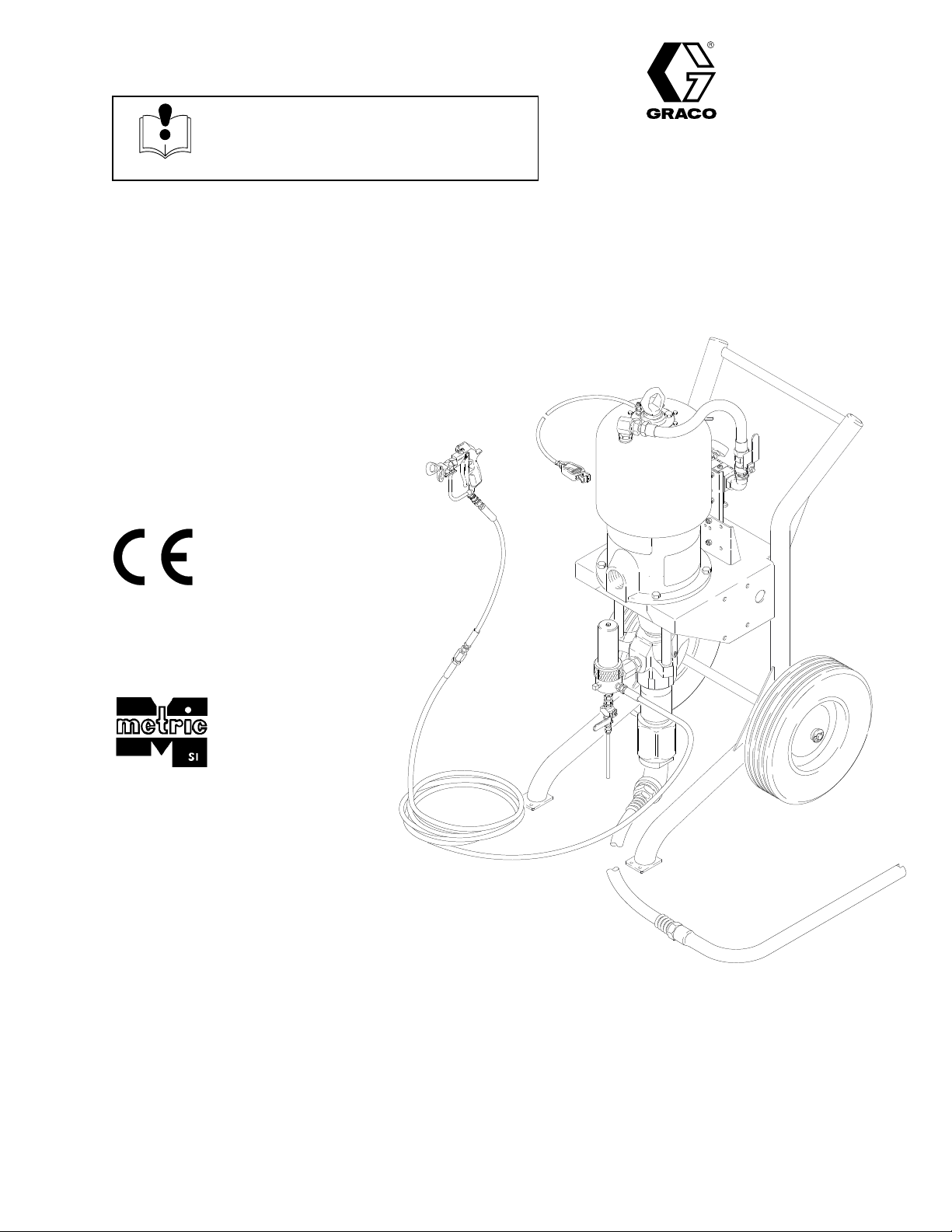
56:1
RA
TIO KING CARBON STEEL
Cart-Mounted
WITH
Refer
DURA-FLO
to page 2 for a List of Models.
900 DISPLACEMENT PUMP
Rev. C
Supersedes B
Airless Package
Table
Warnings 2.
Setup 6
Operation 8
Parts 12
Technical
Dimensions 19
Graco Warranty and Disclaimers
Toll-Free
. . . . . . . . . . . . . . . . . . . . . . . . . . . . . . . . . . . . .
. . . . . . . . . . . . . . . . . . . . . . . . . . . . . . . . . . . . . . . . .
. . . . . . . . . . . . . . . . . . . . . . . . . . . . . . . . . . . . .
. . . . . . . . . . . . . . . . . . . . . . . . . . . . . . . . . . . . . . . .
Data
Graco Phone Numbers
of Contents
. . . . . . . . . . . . . . . . . . . . . . . . . . . . . . .
. . . . . . . . . . . . . . . . . . . . . . . . . . . . . . . . . . .
. . . . . . . . . . . . . . .
. . . . . . . . . . . . . . .
GRACO INC. P.O. BOX 1441
COPYRIGHT
Graco
Inc. is registered to I.S. EN ISO 9001
18.
20.
20.
MINNEAPOLIS, MN
1994, GRACO INC.
Model
55440–1441
237–296 Shown
06223
Page 2
List
of Models
Part
No.
236–477 B Kingt 56:1
237–296 B Kingt
237–281 B Kingt
237–285 B
238–906 B
Series
Pump Model
, with hose and gun
, with surge tank
Reduced Icing Quiet
Kingt
Reduced Icing Quiet
Kingt
, with hose and gun
Ratio
56:1
56:1
56:1
56:1
Symbols
Warning Symbol
WARNING
This
symbol alerts you to the possibility of serious
injury or death if you do not follow the instructions.
Maximum Fluid
W
orking Pressure
5000 psi (345 bar
5000 psi (345 bar
5000 psi (345 bar
5000 psi (345 bar
5000 psi (345 bar
. 34.5 MPa)
. 34.5 MPa)
. 34.5 MPa)
. 34.5 MPa)
. 34.5 MPa)
Maximum Air
Input Pressure
90 psi (6 bar
90 psi (6 bar
90 psi (6 bar
90 psi (6 bar
90 psi (6 bar
, 0.6 MPa)
, 0.6 MPa)
, 0.6 MPa)
, 0.6 MPa)
, 0.6 MPa)
Caution Symbol
CAUTION
This
symbol alerts you to the possibility of damage to
or destruction of equipment if you do not follow the
instructions.
INSTRUCTIONS
WARNING
EQUIPMENT MISUSE HAZARD
Equipment
D
This equipment is for professional use only
D
Read all instruction manuals, tags, and labels before operating the equipment.
D
Use the equipment only for its intended purpose. If you are not sure, call your Graco distributor
D
Do not alter or modify this equipment.
D
Check equipment daily
D
Do not exceed the maximum working pressure of the lowest rated system component. Refer to the
T
D
Use fluids and solvents which are compatible with the equipment wetted parts. Refer to the
nical Data
D
Do not use hoses to pull equipment.
D
Route hoses away from traffic areas, sharp edges, moving parts, and hot surfaces. Do not expose
Graco hoses to temperatures above 180
misuse can cause the equipment to rupture or malfunction and result in serious injury
.
echnical Data
section of all equipment manuals. Read the fluid and solvent manufacturer’s warnings.
. Repair or replace worn or damaged parts immediately
on page 18 for the maximum working pressure of this equipment.
_F (82_
C) or below –40
_F (–40_C).
.
.
.
Tech-
D W
D
D
ear hearing protection when operating this equipment.
Do not lift pressurized equipment.
Comply with all applicable local, state, and national fire, electrical, and safety regulations.
Page 3
WARNING
INJECTION HAZARD
Spray
from the gun, leaks or ruptured components can inject fluid into your body and cause extremely
serious injury, including the need for amputation. Fluid splashed in the eyes or on the skin can also
cause serious injury
Fluid injected into the skin might look like just a cut, but it is a serious injury. Get immediate medi
cal attention.
Do not point the gun at anyone or at any part of the body
Do not put your hand or fingers over the spray tip.
Do not stop or deflect leaks with your hand, body
Do not “blow back” fluid; this is not an air spray system.
Always have the tip guard and the trigger guard on the gun when spraying.
Check the gun dif
Be sure the gun trigger safety operates before spraying.
Lock the gun trigger safety when you stop spraying.
.
fuser operation weekly
.
, glove or rag.
. Refer to the gun manual.
-
Follow the
checking or servicing the equipment.
T
ighten all fluid connections before operating the equipment.
Check the hoses, tubes, and couplings daily
Do not repair high pressure couplings; you must replace the entire hose.
Use only Graco approved hoses. Do not remove the spring guard that is used to help protect the
hose from rupture caused by kinks or bends near the couplings.
Pressure Relief Procedure
on page 8 if the spray tip clogs and before cleaning,
. Replace worn or damaged parts immediately.
MOVING PARTS HAZARD
Moving
parts, such as the air motor piston, can pinch or amputate your fingers.
Keep clear of all moving parts when starting or operating the pump.
Before servicing the equipment, follow the
equipment from starting unexpectedly
Pressure Relief Procedure
.
on page 8 to prevent the
Page 4
WARNING
FIRE AND EXPLOSION HAZARD
Improper
result in a fire or explosion and serious injury
grounding, poor ventilation, open flames or sparks can cause a hazardous condition and
.
Ground the equipment and the object being sprayed. Refer to
If there is any static sparking or you feel an electric shock while using this equipment,
ing immediately. Do not use the equipment until you identify and correct the problem.
Provide fresh air ventilation to avoid the buildup of flammable fumes from solvents or the fluid
being sprayed.
Keep the spray area free of debris, including solvent, rags, and gasoline.
Electrically disconnect all equipment in the spray area.
Extinguish all open flames or pilot lights in the spray area.
Do not smoke in the spray area.
Do not turn on or of
Do not operate a gasoline engine in the spray area.
f any light switch in the spray area while operating or if fumes are present.
Grounding
on page 5.
TOXIC FLUID HAZARD
stop spray-
Hazardous
inhaled, or swallowed.
Know the specific hazards of the fluid you are using.
Store hazardous fluid in an approved container
state and national guidelines.
Always wear protective eyewear
solvent manufacturer
fluid or toxic fumes can cause serious injury or death if splashed in the eyes or on the skin,
, gloves, clothing and respirator as recommended by the fluid and
.
. Dispose of hazardous fluid according to all local,
Page 5
Setup
General Information
NOTE:
in the text refer to the callouts in the figures and the
parts drawing.
NOTE:
sories, available from your Graco distributor
the Product Data Sheet for the pump, Form No.
305–787. If you supply your own accessories, be sure
they are adequately sized and pressure rated for your
system.
Fig. 2 is only a guide for selecting and installing sys
tem components and accessories. Contact your Graco
distributor for assistance in designing a system to suit
your particular needs.
Reference numbers and letters in parentheses
Always use Genuine Graco Parts and Acces
. Refer to
-
-
Prepare the Operator
All
persons who operate the equipment must be
trained in the safe, ef
components as well as the proper handling of all fluids.
All operators must thoroughly read all instruction
manuals, tags, and labels before operating the equip
ment.
ficient operation of all system
-
Grounding
WARNING
FIRE AND EXPLOSION HAZARD
Before operating the pump, ground the
system as explained below
the section
ARD
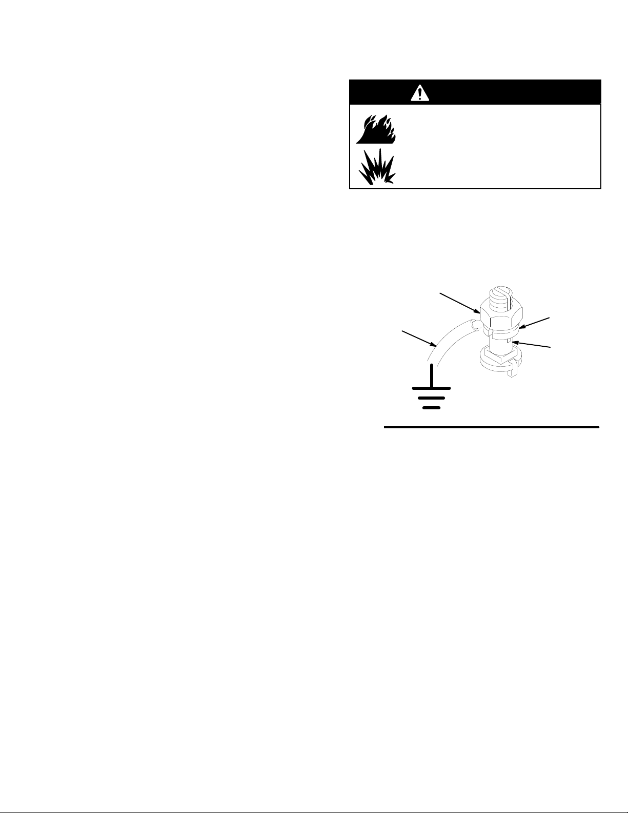
1.
Pump:
use the ground wire and clamp (supplied).
See Fig. 1. Loosen the grounding lug locknut (W)
and washer (X). Insert one end of the ground wire
(26) into the slot in lug (Z) and tighten the locknut
securely
true earth ground.
. Connect the other end of the wire to a
26
FIRE OR EXPLOSION HAZ
on page 4.
W
. Also read
-
X
Z
Prepare the Site
The
pump requires 150 scfm (4.2 m/min) of com
pressed air while operating at 90 psi (6 bar
air pressure and 60 cycles per minute. Ensure that you
have an adequate compressed air supply
Refer to Fig. 2. Bring a compressed air supply line (A)
from the air compressor to the pump location. Be sure
all air hoses (A) are properly sized and pressure-rated
for your system. Use only electrically conductive
hoses. The air hose should have a 3/4 npsm(m)
thread.
Install a bleed-type shutoff valve (B) in the air line to
isolate the air line components for servicing. Install an
air line moisture trap and drain valve (C) to help re
move moisture from the compressed air supply
Keep the site clear of any obstacles or debris that
could interfere with the operator’s movement.
Have a grounded, metal pail available for use when
flushing the system or draining the fluid filter
.
-
, 0.6 MPa)
-
.
.
Fig. 1
2.
Air and fluid hoses:
hoses.
3.
Air compressor:
dations.
4.
Spray gun:
erly grounded fluid hose and pump.
5.
Fluid supply container:
6.
Object being sprayed:
7.
Solvent pails used when flushing:
code. Use only metal pails, which are conductive,
placed on a grounded surface. Do not place the
pail on a nonconductive surface, such as paper or
cardboard, which interrupts the grounding continu
ity.
8.
T
o maintain grounding continuity when flushing or
relieving pressure
gun firmly to the side of a grounded
then trigger the gun.
ground through connection to a prop
use only electrically conductive
follow manufacturer’s recommen
follow your local code.
follow your local code.
follow your local
, hold a metal part of the spray
metal
-
-
-
pail,
Page 6

Setup
Supplied Components
Refer
to Fig. 2.
WARNING
A red-handled bleed-type master air valve (F) and
a fluid drain valve (D) are supplied. These accesso
ries help reduce the risk of serious injury
fluid injection and splashing of fluid in the eyes or
on the skin, and injury from moving parts if you are
adjusting or repairing the pump.
The bleed-type master air valve relieves air trapped
between this valve and the pump after the air is
shut of
f. T
rapped air can cause the pump to cycle
unexpectedly
The fluid drain valve assists in relieving fluid pres
sure in the displacement pump, hose, and gun.
T
riggering the gun to relieve pressure may not be
sufficient.
The red-handled bleed-type master air valve (F)
is required in your system to relieve air trapped
between it and the air motor when the valve is
closed (see the
bleed valve is easily accessible from the pump, and
is located
(H).
The air filter/regulator (H) controls pump speed
and outlet pressure by adjusting the air pressure to
the pump. It also removes harmful dirt and moisture
from the compressed air supply
pump, but
valve (F).
. Locate the valve close to the pump.
WARNING
downstream
upstream
above). Be sure the
from the air filter/regulator
. Locate close to the
from the bleed-type master air
, including
-
The air manifold (J)
lines to air-powered accessories.
The air relief valve (38)
prevent overpressurization of the pump.
The fluid filter (4) or surge tank
-
mesh (250 micron) stainless steel element to filter
particles from the fluid as it leaves the pump. It
includes the
quired in your system to relieve fluid pressure in the
hose and gun (see the
The suction hose (8) and tube (7)
to draw fluid from a 5 gallon (19 liter) pail.
fluid drain valve (D),
provides ports for connecting
opens automatically to
includes a 60
WARNING
which is re
at left).
allow the pump
-
Connect the Fluid Hoses and Gun
NOTE:
hoses, a spray gun, and connecting parts (ref. nos.
102–106). If you supply your own fluid hoses and gun,
be sure they are properly sized and pressure-rated for
your system. Use only electrically conductive hoses.
1.
2.
3.
4.
5.
Models 237–296 and 238–906 include fluid
Connect the main fluid hose (103) to the fluid filter
(4) outlet.
Screw the coupling (105) onto the other end of the
main fluid hose (103).
Screw the short whip hose (104) onto the coupling
(105).
Screw the whip hose (104) onto the gun swivel
(106).
Screw the gun swivel (106) onto the fluid inlet of
the spray gun (102).
Page 7

KEY
SUPPLIED
1 Pump
2 Cart
4
D
7
8
19
F
G
H
J
25
26
38
WITH ALL MODELS
Fluid Filter (includes drain valve D)
(surge tank on Model 237–281)
Fluid Drain V
Suction T
Suction Hose
Air Regulation Kit (includes items
F
, G, H, and J)
Red-Handled Bleed-T
Air V
Air Line Inlet Swivel
Pump Air Filter/Regulator
Air Manifold
Pump Air Hose
Ground Wire (required; see page 5
for installation instructions)
Air Relief V
alve (required)
ube
ype Master
alve (required, for pump)
alve (partially hidden)
Setup
SUPPLIED WITH MODELS 237–296 AND
238–906 ONL
102
Airless Spray Gun
103
Electrically Conductive Fluid
Supply Hose
104
Electrically Conductive Fluid Whip Hose
105 Coupling
Gun Swivel
106
Y
C
COMPONENTS YOU MUST SUPPL
A
Electrically Conductive Air Supply Hose
B Bleed-T
C
E
ype Master Air V
(for accessories)
Air Line Moisture Trap and Drain V
Grounded 5 Gallon (19 Liter) Pail
alve
B
25
Y
alve
103
105
104
102
26
106
4
D
J
Detail of Air Line Connection
H
and Air Regulation Kit (19)
A
25
F
G
38
F
2
1
8
7
E
Fig. 2
Model 237–296 Shown
06225
Page 8

Operation
Pressure Relief Procedure
WARNING
INJECTION
The system pressure must be manually
relieved to prevent the system from
starting or spraying accidentally
under high pressure can be injected through the
skin and cause serious injury
an injury from injection, splashing fluid, or moving
parts, follow the
whenever you:
are instructed to relieve the pressure,
stop spraying,
check or service any of the system equipment,
or install or clean the spray tips.
1.
Lock the gun trigger safety
2.
Close the red-handled bleed-type master air valve
(F
, required in your system).
3.
Unlock the gun trigger safety
HAZARD
. Fluid
. T
o reduce the risk of
Pressure Relief Procedure
.
.
Packing Nut/Wet-Cup
Before
starting, fill the packing nut (K) 1/3 full with
Graco Throat Seal Liquid (TSL) or compatible solvent.
See Fig. 3.
WARNING
T
o reduce the risk of serious injury whenever you
are instructed to relieve pressure, always follow the
Pressure Relief Procedure
The packing nut is torqued at the factory and is ready
for operation. If it becomes loose and there is leaking
from the throat packings,
torque the nut to 100–1
the supplied wrench. Do this whenever necessary
not overtighten the packing nut.
10 ft-lb (136–149 N.m) using
Flush the Pump Before First Use
at left.
relieve pressure,
then
. Do
4.
Hold a metal part of the gun firmly to the side of a
grounded metal pail, and trigger the gun to relieve
pressure.
5.
Lock the gun trigger safety
6.
Open the drain valve (D, required in your system),
having a container ready to catch the drainage.
7.
Leave the drain valve open until you are ready to
spray again.
If you suspect that the spray tip or hose is completely
clogged, or that pressure has not been fully relieved
after following the steps above, very slowly
tip guard retaining nut or hose end coupling and relieve
pressure gradually
the tip or hose.
, then loosen completely
.
loosen the
. Now clear
The
pump is tested with lightweight oil, which is left in
to protect the pump parts. If the fluid you are using
may be contaminated by the oil, flush it out with a
compatible solvent. See
Flushing
on page 10.
Using the Airless Spray Gun
Before
operating the equipment, read the instruction
manual supplied with the gun.
Spray some test patterns before doing any finished
work. Refer to the gun manual for detailed information
on correct spraying technique.
Page 9

Operation
CAUTION
T
o avoid tip-over
surface. Failure to follow this caution could result in
injury or equipment damage.
Prime the Pump
1. See
2.
3.
4.
5.
Fig. 3. Remove the tip guard and spray tip
from the gun (102). See the gun instruction manu
al.
Close the air filter/regulator (H) and bleed-type air
valves (B, F).
Close the fluid drain valve (D).
Connect the air line (A) to the air inlet swivel (G).
Check that all fittings throughout the system are
tightened securely
, the cart must be on a flat and level
.
Set the Air and Fluid Pressure
WARNING
To
reduce the risk of serious injury whenever you
are instructed to relieve pressure, always follow the
Pressure Relief Procedure
1.
Relieve the pressure. Install the tip guard and
-
spray tip in the gun, as explained in the gun manu
al.
2.
Open the air filter/regulator (H) slowly
regulator to control pump speed and fluid pres
sure. Always use the lowest air pressure neces
sary to get the desired results. Higher pressures
cause premature tip and pump wear
NOTE: T
T
-handle in (clockwise). T
handle counterclockwise. T
tighten the jam nut.
o open the air filter/regulator
on page 8.
. Use the
.
, turn the
o close the regulator
o lock the regulator setting,
, turn the
-
-
-
6.
Place the suction tube (7) into the fluid supply
container.
7.
Open the bleed-type air valves (B, F).
8.
Hold a metal part of the gun (102) firmly to the side
of a grounded metal pail and hold the trigger open.
9.
Slowly open the air filter/regulator (H) until the
pump starts.
10.
Cycle the pump slowly until all air is pushed out
and the pump and hoses are fully primed.
11.
Release the gun trigger and lock the trigger safety
The pump should stall against pressure.
12.
If the pump fails to prime properly
valve (D). Use the drain valve as a priming valve
until the fluid flows from the valve. Close the valve.
NOTE:
and gun already primed, open the drain valve (D) to
help prime the pump and vent air before it enters the
hose. Close the drain valve when all air is eliminated.
When changing fluid containers with the hose
, open the drain
WARNING
COMPONENT RUPTURE HAZARD
T
o reduce the risk of overpressurizing
your system, which could cause compo
nent rupture and serious injury,
exceed the specified Maximum Incoming Air Pres
sure to the pump
page 18).
3.
With the pump and lines primed, and with ade
quate air pressure and volume supplied, the pump
will start and stop as you open and close the gun.
.
(see the Technical Data,
never
on
-
-
-
CAUTION
Do not allow the pump to run dry
accelerate to a high speed, causing damage. If your
pump is running too fast, stop it immediately and
check the fluid supply
air has been pumped into the lines, refill the con
tainer and prime the pump and the lines, or flush and
leave it filled with a compatible solvent. Eliminate all
air from the fluid system.
. If the container is empty and
. It will quickly
-
Page 10

Shutdown and Care of the Pump
Operation
CAUTION
WARNING
To
reduce the risk of serious injury whenever you
are instructed to relieve pressure, always follow the
Pressure Relief Procedure
For overnight shutdown, stop the pump at the bottom
of its stroke to prevent fluid from drying on the ex
posed displacement rod and damaging the throat
packings.
Always flush the pump before the fluid dries on the
displacement rod. See
Relieve the pressure.
on page 8.
Flushing
below
-
.
Flushing
WARNING
FIRE AND EXPLOSION HAZARD
Before flushing, read the section
OR EXPLOSION HAZARD
Be sure the entire system and flushing
pails are properly grounded. Refer to
Grounding
on page 5.
FIRE
on page 4.
Never leave water or water-base fluid in the pump
overnight. If you are pumping water-base fluid, flush
with water first, then with a rust inhibitor such as
mineral spirits. Relieve the pressure, but leave the
rust inhibitor in the pump to protect the parts from
corrosion.
WARNING
T
o reduce the risk of serious injury whenever you
are instructed to relieve pressure, always follow the
Pressure Relief Procedure
1.
Relieve the pressure.
2.
Remove the tip guard and spray tip from the gun.
See the gun instruction manual.
3.
Remove the filter element from the fluid filter (4) or
surge tank. Reinstall the filter or surge tank bowl.
4.
Place the suction tube (7) in a container of solvent.
5.
Hold a metal part of the gun firmly to the side of a
grounded
metal
pail.
on page 8.
Flush the pump:
Before the first use
When changing colors or fluids
Before fluid can dry or settle out in a dormant pump
(check the pot life of catalyzed fluids)
Before storing the pump.
Flush with a fluid that is compatible with the fluid you
are pumping and with the wetted parts in your system.
Check with your fluid manufacturer or supplier for
recommended flushing fluids and flushing frequency
.
6.
Start the pump. Always use the lowest possible
fluid pressure when flushing.
7. T
rigger the gun.
8.
Flush the system until clear solvent flows from the
gun.
9.
Relieve the pressure.
10.
Clean the tip guard, spray tip, and fluid filter ele
ment separately
11.
Clean the inside and outside of the suction tube
(7).
, then reinstall them.
-
10 308-425
Page 11

KEY
4 Fluid
D
7
8
102
103
A
B Bleed-T
F
G
H
K
Filter (includes drain valve D)
(surge tank on Model 237–281)
Fluid Drain V
Suction T
Suction Hose
Airless Spray Gun
Electrically Conductive Fluid Supply Hose
Main Air Line
Red-Handled Bleed-T
Air V
Air Line Inlet Swivel
Pump Air Filter/Regulator
Packing Nut/W
alve (required)
ube
ype Master Air V
alve (required, for pump)
et-Cup
alve (for accessories)
ype Master
Operation
Detail of Air Line Connection
and Air Regulation Kit (19)
B
H
1
103
orque to 100–1
T
102
10 ft-lb (136–149 N.m)
K
1
4
D
A
F
G
F
8
7
Fig. 3
06225
Model 237–296 Shown
308-425 11
Page 12

Parts
Part No. 236–477, Series B (includes items 1–38)
Part No. 237–296, Series B (includes items 1–106)
105
103
104
106
19
26
1
15
2d
16
17
10
13
11
12
4
34
37
35
2
33
36
2c
2525 (Ref)
38102
2a
103
(Ref)
14
6
5
2b
87
12 308-425
Page 13

Parts
Part No. 236–477, Series B (includes items 1–38)
Part No. 237–296, Series B (includes items 1–106)
Ref.
No. Part No. Description Qty.
1 236–475 PUMP
, King, 56:1 ratio;
See manual 308–353 for parts
2 238–271 CART
2a 113–362 . WHEEL 2
2b 113–436 .
2c 113–361 . CAP 2
2d 191–605 . BRACKET 1
4 238–620
, portable
Includes replaceable items 2a–2d
RING, retaining
FLUID FIL
(60 mesh) stainless steel element
and drain valve
TER, with 250 micron
See manual 307–296 for parts
5 112–839 BUSHING, reducer; 2” npt(m) x
1” npt(f); zinc-plated malleable iron
6 100–088 ELBOW
chrome-plated malleable iron
7 169–528
8 237–522
9 206–994 THROAT SEAL LIQUID;
10 190–439
11 190–411
12 190–412 NUT
13 112–973 O-RING; PTFE r 1
14 156–849
TUBE, suction; aluminum
HOSE, suction; nylon; 1 in. (25 mm) ID;
1” npt (mbe); 6 ft (1.8 m) long
8 oz (0.5 liter); not shown
NIPPLE; 1” npt x 1–3/8 unf–2a;
carbon steel
ADAPTER; 3/4 npt(m); carbon steel
NIPPLE; 3/8 npt
, street, 90_; 2” npt(m x f);
; 1–3/8 unf–2b; carbon steel
Ref.
No. Part No. Description Qty.
15 100–004 CAPSCREW
1
16 100–133 LOCKW
1
17 100–131 NUT
19 238–881 AIR REGULATION KIT
2
25 238–374
26 238–909 GROUND WIRE AND CLAMP 1
33 111–040 NUT
34 100–057 SCREW
1
35 191–383 BRACKET
1
36 113–428 SCREW, hex socket;
1
37 102–040 NUT
1
38 103–347 RELIEF VAL
1
102 238–591 AIRLESS SPRAY GUN
1.25 in. (31 mm) long
, full, hex; 3/8–16 unc–2b
See manual 308–648 for parts
HOSE, air; 3/4 in. (19 mm) ID;
3/4 npt (mbe); 21 in. (533 mm) long
, lock; with nylon insert; 5/16–18
5/16–18 x 3/4 in. (19 mm) long
1/4–20 x 1 in. (25 mm) long
, lock, hex; 1/4–20
100 psi (7 bar
, hex hd; 3/8–16 unc–2a;
ASHER, external tooth; 3/8”
, cap, hex hd;
, mounting
VE, air;
, 0.7 MPa)
See manual 308–236 for parts
1
103 238–396
1
1
104 238–383
1
105 150–287
1
106 189–018
HOSE, fluid; nylon; 3/8 in. (9.5 mm) ID;
3/8 npt(m) x 3/8 npsm(f);
50 ft (15.2 m) long
HOSE, fluid; nylon; 1/4 in. (6.3 mm) ID;
1/4 npsm (fbe); 6 ft (1.8 m) long
COUPLING; 1/4 npt(m) x 3/8 npt(f)
SWIVEL, gun
4
4
4
1
1
4
4
1
4
4
1
1
1
1
1
1
308-425 13
Page 14

Part No. 237–281, Series B
Parts
29
30
10
13
11
12
25 (Ref)
26
1
15
31
2d
32
16
17
4
19
34
37
35
2
33
36
2c
25
38
2a
14
6
5
87
2b
06221
14 308-425
Page 15

Part No. 237–281, Series B
Parts
Ref.
No. Part No. Description Qty.
1 236–475 PUMP
, King, 56:1 ratio;
See manual 308–353 for parts
2 238–271 CART
2a 113–362 . WHEEL 2
2b 113–436 .
2c 113–361 . CAP 2
2d 191–605 . BRACKET 1
4 238–623 HIGH PRESSURE SURGE TANK,
, portable
Includes replaceable items 2a–2d
RING, retaining
with 250 micron (60 mesh)
stainless steel element and drain valve
See manual 307–296 for parts
5 112–839 BUSHING, reducer; 2” npt(m) x
1” npt(f); zinc-plated malleable iron
6 100–088 ELBOW
chrome-plated malleable iron
7 169–528
8 237–522
9 206–994 THROAT SEAL LIQUID;
10 190–439
11 190–411
12 190–412 NUT
TUBE, suction; aluminum
HOSE, suction; nylon; 1 in. (25 mm) ID;
1” npt (mbe); 6 ft (1.8 m) long
8 oz (0.5 liter); not shown
NIPPLE; 1” npt x 1–3/8 unf–2a;
carbon steel
ADAPTER; 3/4 npt(m); carbon steel
, street, 90_; 2” npt(m x f);
; 1–3/8 unf–2b; carbon steel
Ref.
No. Part No. Description Qty.
13 112–973 O-RING; PTFE r 1
14 156–849
1
15 100–004 CAPSCREW
1
16 100–133 LOCKW
2
17 100–131 NUT
19 238–881 AIR REGULATION KIT
25 214–953
26 238–909 GROUND WIRE AND CLAMP 1
1
29 238–630 CLAMP
30 100–902 SCREW
1
31 100–015 NUT
1
32 100–016 LOCKW
1
33 111–040 NUT
34 100–057 SCREW
1
35 191–383 BRACKET
1
36 113–428 SCREW, hex socket;
1
37 102–040 NUT
1
38 103–347 RELIEF VAL
1
NIPPLE; 3/8 npt
, hex hd; 3/8–16 unc–2a;
1.25 in. (31 mm) long
ASHER, external tooth; 3/8”
, full, hex; 3/8–16 unc–2b
See manual 308–648 for parts
HOSE, air; 3/4 in. (19 mm) ID;
3/4 npt (mbe); 15 in. (381 mm) long
, surge tank
, round hd machine;
1/4–20; 38 mm long
, hex; 1/4–20
ASHER, spring; 1/4”
, lock; with nylon insert; 5/16–18
, cap, hex hd;
5/16–18 x 3/4 in. (19 mm) long
, mounting
1/4–20 x 1 in. (25 mm) long
, lock, hex; 1/4–20
VE, air;
100 psi (7 bar
, 0.7 MPa)
1
4
4
4
1
1
1
1
1
1
4
4
1
4
4
1
308-425 15
Page 16

Parts
Part No. 237–285, Series B (includes items 1–38)
Part No. 238–906, Series B (includes items 1–106)
1
25 (Ref)
26
19
36
25
105
103
104
106
15
34
2d
16
17
10
13
11
12
4
14
37
35
2
33
2c
38102
2a
16 308-425
103
(Ref)
6
5
2b
87
06229
Page 17

Parts
Part No. 237–285, Series B (includes items 1–38)
Part No. 238–906, Series B (includes items 1–106)
Ref.
No. Part No. Description Qty.
1 237–278 PUMP
2 238–271 CART
2a 113–362 . WHEEL 2
2b 113–436 .
2c 113–361 . CAP 2
2d 191–605 . BRACKET 1
4 238–620
5 112–839 BUSHING, reducer; 2” npt(m) x
6 100–088 ELBOW
7 169–528
8 237–522
9 206–994 THROAT SEAL LIQUID;
10 190–439
11 190–411
12 190–412 NUT
13 112–973 O-RING; PTFE r 1
14 156–849
, King, 56:1 ratio;
See manual 308–353 for parts
, portable
Includes replaceable items 2a–2d
RING, retaining
FLUID FIL
(60 mesh) stainless steel element
and drain valve
See manual 307–296 for parts
1” npt(f); zinc-plated malleable iron
chrome-plated malleable iron
TUBE, suction; aluminum
HOSE, suction; nylon; 1 in. (25 mm) ID;
1” npt (mbe); 6 ft (1.8 m) long
8 oz (0.5 liter); not shown
NIPPLE; 1” npt x 1–3/8 unf–2a;
carbon steel
ADAPTER; 3/4 npt(m); carbon steel
NIPPLE; 3/8 npt
TER, with 250 micron
, street, 90_; 2” npt(m x f);
; 1–3/8 unf–2b; carbon steel
Ref.
No. Part No. Description Qty.
15 100–004 CAPSCREW
1
16 100–133 LOCKW
1
17 100–131 NUT
19 238–881 AIR REGULATION KIT
2
25 214–953
26 238–909 GROUND WIRE AND CLAMP 1
33 111–040 NUT
34 100–057 SCREW
1
35 191–383 BRACKET
1
36 113–428 SCREW, hex socket;
1
37 102–040 NUT
1
38 103–347 RELIEF VAL
1
102 238–591 AIRLESS SPRAY GUN
1
103 238–396
1
1
104 238–383
1
105 150–287
1
106 189–018
1.25 in. (31 mm) long
, full, hex; 3/8–16 unc–2b
See manual 308–648 for parts
HOSE, air; 3/4 in. (19 mm) ID;
3/4 npt (mbe); 15 in. (381 mm) long
, lock; with nylon insert; 5/16–18
5/16–18 x 3/4 in. (19 mm) long
1/4–20 x 1 in. (25 mm) long
, lock, hex; 1/4–20
100 psi (7 bar
See manual 308–236 for parts
HOSE, fluid; nylon; 3/8 in. (9.5 mm) ID;
3/8 npt(m) x 3/8 npsm(f);
50 ft (15.2 m) long
HOSE, fluid; nylon; 1/4 in. (6.3 mm) ID;
1/4 npsm (fbe); 6 ft (1.8 m) long
COUPLING; 1/4 npt(m) x 3/8 npt(f)
SWIVEL, gun
, hex hd; 3/8–16 unc–2a;
ASHER, external tooth; 3/8”
, cap, hex hd;
, mounting
VE, air;
, 0.7 MPa)
4
4
4
1
1
4
4
1
4
4
1
1
1
1
1
1
Manual
Cart Change:
Change Summary
All models now use Part No. 238–271
Cart.
Air Regulation Kit:
238–881 Air Regulation Kit.
Ground W
ire:
All models now use Part No. 238–909
Ground Wire.
Series Levels:
Added Model:
All models advance to Series B.
Model 238–906 is added to the manual.
All models now use Part No.
308-425 17
Page 18

Technical
PTFEPTFEPTFE
Category Data
Maximum
Maximum air input pressure 90 psi (6 bar
Ratio 56:1
Pump performance data
Air consumption data
Air inlet size
Fluid outlet size (at fluid filter)
Fluid inlet size
Maximum operating temperature
W
etted parts
fluid working pressure
r
is a registered trademark of the DuPont Co.
5000 psi (345 bar
See pump manual 308–353
See pump manual 308–353
3/4 npsm(f)
3/8 npt(m)
2 in. npt(f)
180_F (82_C)
Pump:
See pump manual 308–353
Fluid Filter/Surge T
Suction Hose and T
Fluid Fittings:
Drain T
ube, Fluid Hoses:
Data
, 34.5 MPa)
, 0.6 MPa)
ank:
See manual 307–296
ube:
Nylon, Aluminum
Zinc-Plated Malleable Iron, Zinc-Plated Carbon Steel
Nylon
Sound Pressure Levels (dBa)
(tested in accordance with ISO 3744)
Input
Air Pressures at 15 cycles per minute
40 psi (2.8 bar
Air Motor
Standard King
Reduced Icing Quiet King 79.0 dBa 80.8 dBa 82.0 dBa 89.0 dBa
0.28 MPa)
79.0 dBa 81.4 dBa 83.0 dBa 90.5 dBa
,
58 psi (4 bar
0.4 MPa)
,
70 psi (4.8 bar
0.48 MPa)
,
90 psi (6 bar
0.6 MPa)
,
18 308-425
Page 19

Model 236–477 Shown
A
Dimensions
B
Pump Model
236–477
237–296
237–281
237–285
238–906
A B C W
51.1 in. (1297 mm)
51.1 in. (1297 mm)
51.1 in. (1297 mm)
51.2 in. (1300 mm)
51.2 in. (1300 mm)
C
idth Across
Wheels
28.1 in. (714 mm) 30.7 in. (780 mm) 26 in. (660 mm)
28.1 in. (714 mm) 30.7 in. (780 mm) 26 in. (660 mm)
28.1 in. (714 mm) 30.7 in. (780 mm) 26 in. (660 mm)
28.1 in. (714 mm) 30.7 in. (780 mm) 26 in. (660 mm)
28.1 in. (714 mm) 30.7 in. (780 mm) 26 in. (660 mm)
06224
Weight
270 lb (123 kg)
295 lb (134 kg)
280 lb (127 kg)
270 lb (123 kg)
295 lb (134 kg)
308-425 19
Page 20

The
WARRANTY
Graco
warrants all equipment listed in this manual which is manufactured by Graco and bearing its name to be free from defects
in material and workmanship on the date of sale by an authorized Graco distributor to the original purchaser for use. Graco will,
for a period of twelve months from the date of sale, repair or replace any part of the equipment determined by Graco to be defec
tive. This warranty applies only when the equipment is installed, operated and maintained in accordance with Graco’
ommendations.
This warranty does not cover
caused by faulty installation, misapplication, abrasion, corrosion, inadequate or improper maintenance, negligence, accident,
tampering, or substitution of non-Graco component parts. Nor shall Graco be liable for malfunction, damage or wear caused by
the incompatibility of Graco equipment with structures, accessories, equipment or materials not supplied by Graco, or the im
proper design, manufacture, installation, operation or maintenance of structures, accessories, equipment or materials not sup
plied by Graco.
This warranty is conditioned upon the prepaid return of the equipment claimed to be defective to an authorized Graco distributor
for verification of the claimed defect. If the claimed defect is verified, Graco will repair or replace free of charge any defective
parts. The equipment will be returned to the original purchaser transportation prepaid. If inspection of the equipment does not
disclose any defect in material or workmanship, repairs will be made at a reasonable charge, which charges may include the
costs of parts, labor
THIS WARRANTY IS EXCLUSIVE, AND IS IN LIEU OF ANY OTHER WARRANTIES, EXPRESS OR IMPLIED, INCLUDING
BUT NOT LIMITED TO WARRANTY OF MERCHANTABILITY OR WARRANTY OF FITNESS FOR A PARTICULAR PURPOSE.
s sole obligation and buyer’s sole remedy for any breach of warranty shall be as set forth above. The buyer agrees that no
Graco’
other
remedy (including, but not limited
, or any other incidental or consequential loss) shall be available. Any action for breach of warranty must be brought within two
erty
(2)
years of the date of sale.
GRACO MAKES NO WARRANTY, AND DISCLAIMS ALL IMPLIED WARRANTIES OF MERCHANTABILITY AND FITNESS
FOR A PARTICULAR PURPOSE IN CONNECTION WITH
SOLD BUT NOT MANUFACTURED BY GRACO.
switches, hose, etc.) are subject to the warranty
tance in making any claim for breach of these warranties.
Graco Warranty and Disclaimers
, and Graco shall not be liable for general wear and tear
, and transportation.
to, incidental or consequential damages for lost profits, lost sales, injury to person or prop
ACCESSORIES, EQUIPMENT
These items sold, but not manufactured by Graco (such as electric motors,
, if any
, of their manufacturer
. Graco will provide purchaser with reasonable assis
, or any malfunction, damage or wear
, MA
TERIALS, OR COMPONENTS
s written rec-
-
-
-
-
-
For Sales to Canadian Customers:
Except
as expressly stated herein, Graco makers no representations, warranties
any goods or services sold, and
cerning
warranty
MERCHANTABLE QUALITY OR FITNESS FOR A PARTICULAR PURPOSE.
LIMITATION OF LIABILITY
In no event will Graco be liable for indirect, incidental, special or consequential damages resulting from Graco supplying equip
ment hereunder
contract, breach of warranty
SPECIAL WARRANTY FOR DURA-FLO DISPLACEMENT PUMP LOWERS
For no additional cost, Graco of
sale by an authorized Graco distributor to the original purchaser for use. All other terms and conditions of the Graco warranty
shall apply
or condition of any kind, whether arising by operation of law or otherwise, including but not limited to,
, or for the furnishing, performance, or use of any products or other goods sold hereto, whether due to a breach of
, the negligence of Graco, or otherwise.
fers an extended warranty for Dura-Flo displacement pump lowers for 36 months from the date of
.
Graco
TO
PLACE AN ORDER
1–800–367–4023 T
, contact your Graco distributor
oll Free
GRACO SHALL NOT BE LIABLE IN ANY MANNER FOR
Phone Numbers
, or call this number to identify the distributor closest to you:
or conditions, express, implied or collateral, con
any other representation,
WARRANTIES OF
-
-
Foreign Offices:
Sales
Belgium, Canada, England, Korea, Switzerland, France, Germany
Offices:
Atlanta, Chicago, Detroit, Los Angeles
GRACO INC. P.O. BOX 1441
PRINTED
IN U.S.A. 308–425 August 1994 Revised June 1996
MINNEAPOLIS, MN
, Hong Kong, Japan
55440–1441
 Loading...