

Page 1
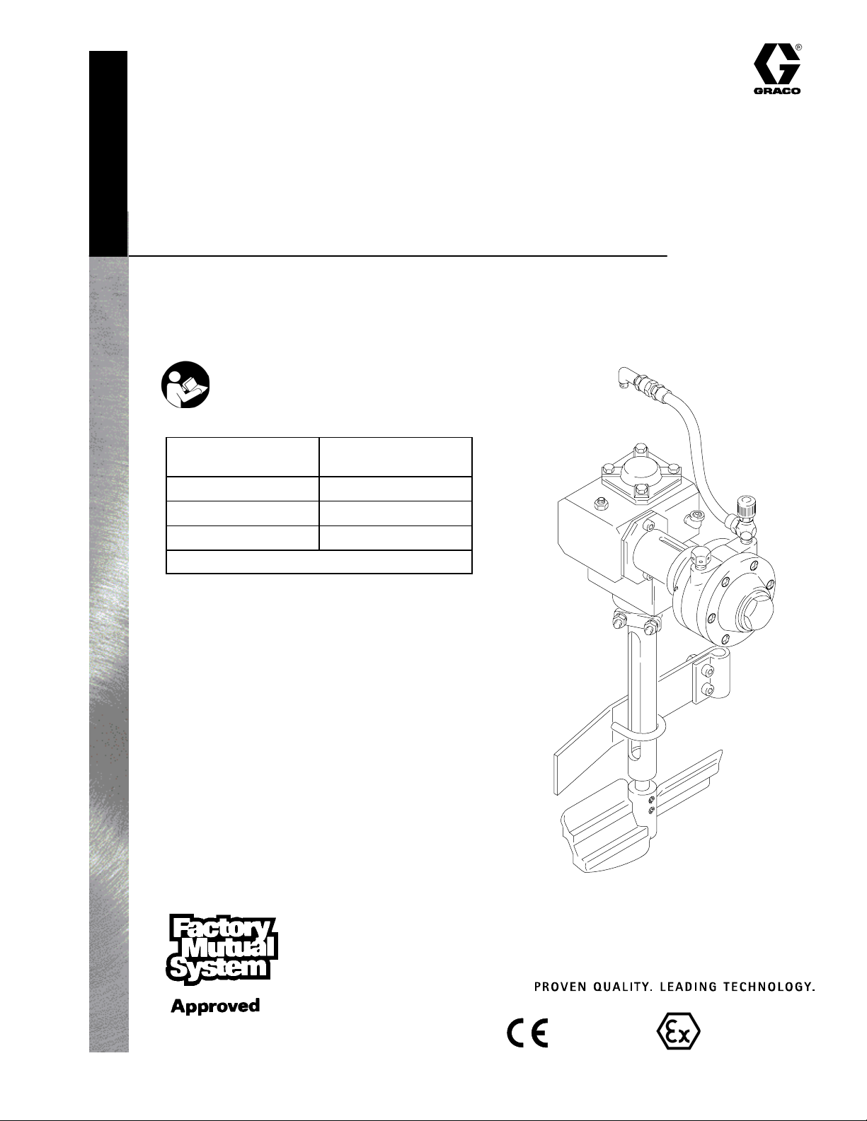
Instructions – Parts List
STAINLESS STEEL, HEAVY–DUTY
Agitators
100 psi (0.7 MPa, 7 bar) Maximum Working Pressure
Important Safety Instructions
Read all warnings and instructions in this manual.
Save these instructions.
Tank Size
gallons (liters)
5 (19) 236661
10 (38) 236662
15 (57) 236663
For fluid viscosities above 800 cps (centipoise)
Table of Contents
Heavy–Duty
Agitator P/N
308371K
Warnings 2. . . . . . . . . . . . . . . . . . . . . . . . . . . . . . . . . . . . . .
Installation 4. . . . . . . . . . . . . . . . . . . . . . . . . . . . . . . . . . . . .
Operation 8. . . . . . . . . . . . . . . . . . . . . . . . . . . . . . . . . . . . .
Service 9. . . . . . . . . . . . . . . . . . . . . . . . . . . . . . . . . . . . . . .
Parts Drawing 12. . . . . . . . . . . . . . . . . . . . . . . . . . . . . . . . .
Parts List 13. . . . . . . . . . . . . . . . . . . . . . . . . . . . . . . . . . . . .
Technical Data 14. . . . . . . . . . . . . . . . . . . . . . . . . . . . . . . .
Graco Standard Warranty 16. . . . . . . . . . . . . . . . . . . . . .
Graco Information 16. . . . . . . . . . . . . . . . . . . . . . . . . . . . .
GRACO INC.ąP.O. BOX 1441ąMINNEAPOLIS, MNą55440-1441
Copyright 2002, Graco Inc. is registered to I.S. EN ISO 9001
0359
Model 236661
03104C
II 1/2 G T6
ITS03ATEX11226
Page 2
Symbols
Warning Symbol
WARNING
This symbol alerts you to the possibility of serious
injury or death if you do not follow the instructions.
WARNING
EQUIPMENT MISUSE HAZARD
Equipment misuse can cause the equipment to rupture or malfunction and result in serious injury.
D This equipment is for professional use only.
D Read all instruction manuals, tags, and labels before operating the equipment.
D Use the equipment only for its intended purpose. If you are not sure, call your Graco distributor.
D Do not alter or modify this equipment.
D Check equipment daily. Repair or replace worn or damaged parts immediately.
Caution Symbol
CAUTION
This symbol alerts you to the possibility of damage to
or destruction of equipment if you do not follow the
instructions.
D Do not exceed the maximum working pressure of the lowest rated component in your system. This
equipment has a 100 psi (0.7 MPa, 7 bar) maximum working pressure.
D Use fluids and solvents which are compatible with the equipment wetted parts. Refer to the
Technical Data section of all equipment manuals. Read the fluid and solvent manufacturer’s
warnings.
D Always wear protective eyewear, gloves, clothing, and respirator as recommended by the fluid and
solvent manufacturer.
D Comply with all applicable local, state, and national fire, electrical, and safety regulations.
2 308371
Page 3
WARNING
FIRE AND EXPLOSION HAZARD
Improper grounding, poor ventilation, open flames, or sparks can cause a hazardous condition and
result in a fire or explosion and serious injury.
D Ground the equipment and the object being sprayed. Refer to Grounding on page 4.
D If there is any static sparking or you feel an electric shock while using this equipment, stop spray-
ing immediately. Do not use the equipment until you identify and correct the problem.
D Do not use 1,1,1–trichloroethane, methylene chloride, other halogenated hydrocarbon solvents, or
fluids containing such solvents in aluminum pumps. Such use could result in a serious chemical
reaction, with the possibility of explosion.
D Do not use kerosene or other flammable solvents or combustible gases to flush the unit.
D Provide fresh air ventilation to avoid the buildup of flammable fumes from solvents or the fluid
being sprayed.
D Keep the spray area free of debris, including solvent, rags, and gasoline.
D Before operating this equipment, electrically disconnect all equipment in the spray area.
D Before operating this equipment, extinguish all open flames or pilot lights in the spray area.
D Do not smoke in the spray area.
D Do not turn on or off any light switch in the spray area while spraying or while there are any fumes
in the air.
D Do not operate a gasoline engine in the spray area.
D Keep a fire extinguisher in the work area.
MOVING PARTS HAZARD
Moving parts, such as the rotating blades of the agitator, can pinch or amputate your fingers or other
body parts and can cause splashing in the eyes or on the skin.
D Keep clear of all moving parts when starting or operating the agitator.
D Always shut off the agitator and disconnect the air line before adjusting the angle of the agitator,
removing the agitator from the drum, or checking or repairing any part of the agitator.
HAZARDOUS VAPORS
Hazardous fluids or toxic fumes can cause serious injury or death if splashed in the eyes or on the
skin, swallowed, or inhaled. When flushing the air motor, keep your face away from the exhaust port.
308371 3
Page 4
WARNING
Installation
Pressure Relief Procedure
FIRE AND EXPLOSION HAZARD
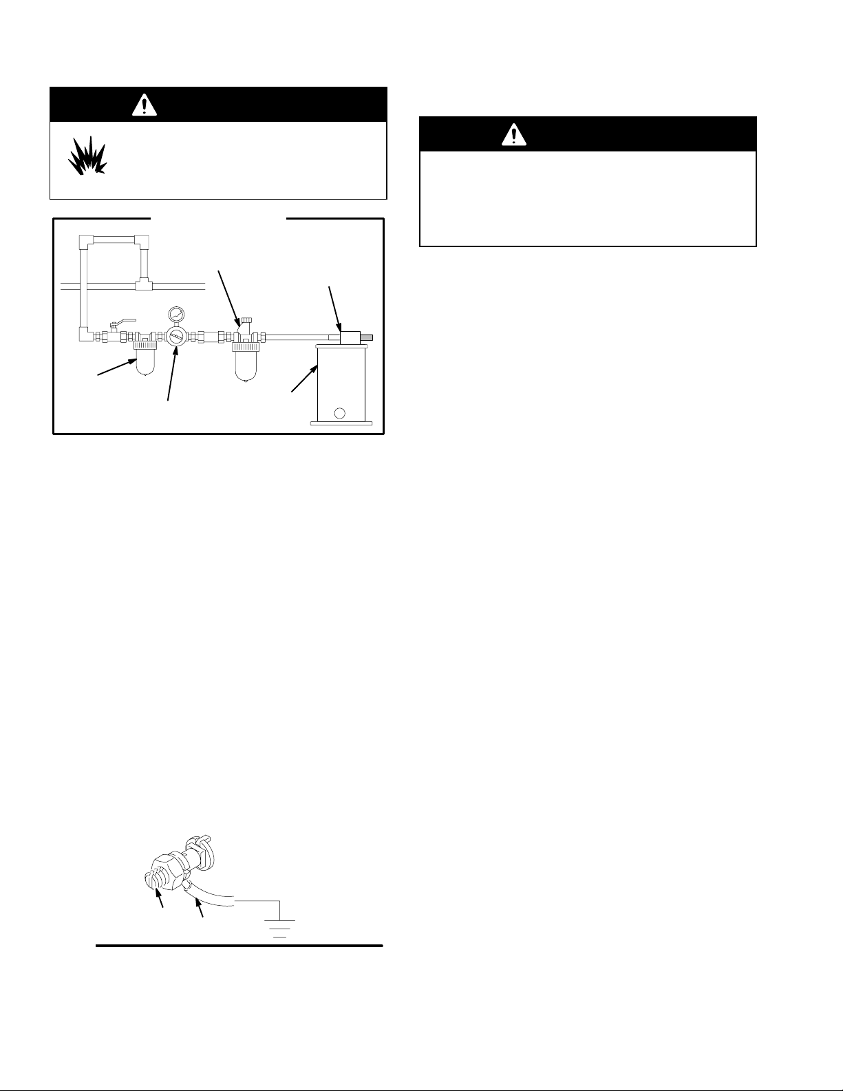
Always maintain a minimum of 1 in.
clearance between rotating agitator parts
and container to prevent sparks from contact.
Typical Installation
air line lubricator
agitator motor
air line filter
air regulator
and gauge
NOTE: Reference numbers and letters in parentheses
refer to the numbers and letters in the Figures and the
Parts Drawings.
mix tank
(reference only)
WARNING
To reduce the risk of serious bodily injury, including
splashing in the eyes or on the skin, or injury from
moving parts, which can result if the tank pressure
is not fully relieved, always follow this procedure
before opening the pressure tank cover or fill port.
1. Shut off the air supply to the tank by closing the air
inlet valve (A). Refer to Fig. 2.
2. Open the drain cock fitting (B) by turning it
counterclockwise.
3. Wait until there is no air escaping through the
fitting before removing the cover or opening the fill
port.
4. Leave the drain cock fitting open until you have
reinstalled the cover or filler cap.
Grounding
Proper grounding is an essential part of maintaining a
safe system.
To reduce the risk of static sparking, all electrically
conductive objects or devices must be properly
grounded. Check your local electrical code for detailed
grounding instructions for your area and type of
equipment.
To ground the agitator, connect one end of the
ground wire (A) to the ground connector (B) on agitator
mounting bracket. See Fig. 1. Connect the other end
of the ground wire to a true earth ground.
For a ground wire and clamp, order
Part No. 237569.
B
A
Fig. 1
4 308371
Page 5

Notes
308371 5
Page 6

Installation
If installing an agitator onto a non-agitated tank,
follow steps 1, 2, and 7 through15. If installing a
heavy-duty agitator in place of a standard agitator,
follow pages 1, 3 through 12, 14, and 15.
1. Follow the Pressure Relief Procedure above.
Then remove the pressure tank cover from the
tank.
2. See Fig. 3. Unscrew and remove the hex jam nut
(C), plug (D), and O-ring (E) from the tank cover.
3. Remove the upper U-bolt (26).
4. See Fig. 4. Loosen the two set screws (13) and
remove the agitator paddle (12).
5. On 10 and 15 gallon tanks, remove the lower
U-bolt (26), loosen screws (24) and slide the baffle
(23) off the fluid tube (K).
6. Unscrew and remove the hex jam nut (C), gasket
(17), and agitator from the tank cover.
7. See Fig. 3. Place the gasket (17) on top of the
tank cover center hole. Insert the agitator drive
shaft (14) through the center hole.
B
5 Gallon Tank with Heavy-Duty Agitator
Fig. 2
A
03282A
NOTE: Position the air motor so it faces away
from the air regulator mounting as shown in Fig. 2.
8. Install the jam nut (C) below the tank cover.
Tighten the jam nut firmly to assure a seal
between the gasket (17) and tank cover.
9. Install the shaft support (11) onto the shaft housing
(9). Clamp with U-bolt (26), clamp (10), lock
washer (36) and nut (25).
10. Tighten the U-bolt at a position leaving
approximately 0.015 in. (0.006 mm) clearance gap
between the thrust washer and the top of the shaft
support. See the Parts Drawing on page 12.
11. See Fig. 4. On the 10 and 15 gallon tanks, place
the lower bearing assembly (2) and (3) on the
shaft. On the 5 gallon tank, clamp U-bolt directly to
shaft support (11). Slide the baffle (23) over the
fluid tube (K) and position the baffle about 1/2 in.
(13 mm) above the highest point on the agitator
paddle (12). Clamp in place with U-bolt (26),
washer (36), and nut (25).
D
E
C
14 (REF)
Fig. 3
14
17
10
36
25
9
F
26
11
03261B
6 308371
Page 7

Installation
12. Align the agitator paddle (12) on the agitator shaft
(14) as instructed for your model, as follows:
Models 236662 and 236663 (10 & 15 Gallon)
Align the top of the paddle hub (G) with the mark
(H) on the agitator shaft (14).
Model 236661 (5 Gallon)
If a 5 gallon pail is to be placed inside the pressure
tank (5 gallon tank only), align the top of the
paddle hub (G) with the upper mark (J) on the
agitator shaft (14). If a pail will not be placed inside
the tank, align top of hub (G) with the lower mark
(H) on the agitator shaft (14).
After the paddle (12) is properly aligned, apply low
strength sealant to the two setscrews (13) and
firmly secure the paddle with the setscrews.
13. See Fig. 5. Remove plug from air inlet manifold
(N). Remove the elbow (37) from the end of the air
hose (21) and attach to the pressure tank’s air inlet
manifold (N).
14. Connect the swivel end of the air hose (21) to the
elbow (37).
15. See Fig. 5. Remove the gear reducer’s oil level
plug (L) from the street elbow and check the oil
level in the reducer housing. The oil should never
be higher than the oil level plug. If necessary, drain
or add oil until the proper oil level is attained.
Screw the oil level plug back onto the street elbow.
J
H
1
Fig. 4
11
2 & 3
25
36
14
12
1/2”
(13 mm)
Apply low strength (cyanoacrylate) thread sealant.
25
24
26
G
1
13
11
K
23
02264
NOTE: Special high temperature synthetic gear oil is
required for the gear reducer. Use only Graco oil,
part number 204559.
308371 7
Page 8

WARNING
Operation
3. Close the tank air regulator(s) by turning the
knob(s) counterclockwise. Turn on the air supply.
To reduce the risk of serious bodily injury, which
can result if the tank pressure is not fully relieved,
always follow the Pressure Relief Procedure on
page 6 before opening the tank cover or fill port.
1. Fill the pressure tank as explained in the Pressure
Tank Instruction Manual 308369.
2. Screw on the filler cap (F) (see Fig. 3), or if the
tank cover was removed, place the agitator and
cover on the pressure tank and secure the cover
with the c-clamp handles (M). See Fig. 5.
WARNING
Over-pressurizing the tank or accessories could
cause a part to rupture. To reduce the risk of
serious injury, including fluid injection and splashing
in the eyes or on the skin, or property damage,
never exceed the maximum air and fluid working
pressure of the lowest rated component in your
system.
4. To start the agitator, slowly open the needle valve
(20). Adjust the speed of the agitator, with the
needle valve, to about 40 to 60 rpm.
CAUTION
Do not operate the agitator at a high speed for a
long period of time. Excessive agitator speed can
cause foaming of fluid (making fluid unusable), or
vibration and increased wear on parts. Always
agitate the fluid only enough to maintain even
mixing.
5. To stop the agitator, close the needle valve (20).
L
Fig. 5
20
N
Heavy-Duty Agitator
37
M
21
03283A
8 308371
Page 9

WARNING
Service
Flushing the Air Motor
To reduce the risk of serious bodily injury, including
cuts, amputation of fingers, and splashing in the
eyes or on the skin, always follow the Pressure
Relief Procedure on page 6, shut off the agitator,
and disconnect the air line before checking or
repairing the agitator.
Lubricating the Heavy-Duty Agitator
CAUTION
Not lubricating the air motor will cause air motor failure.
Air Motor: Install an air line lubricator for automatic air
motor lubrication. Set the lubricator feed rate at 1 drop
of oil per minute for high speed or continuous duty
usage. Do not overfeed oil or exhaust air may become
contaminated. To order a 3/8 in. npt air line lubricator,
order Part No. 214847.
If an air line lubricator is not installed, the air motor
must be manually lubricated every 8 hours. Lubricate
the agitator air motor by placing 10–20 drops of SAE
#10 light oil in the motor’s air inlet. Run the agitator for
about 30 seconds.
Gear Reducer: After the first 100 hours or two weeks
of operation, remove the oil plug (T) and the oil level
plug (L), drain the oil, and thoroughly flush the housing
with light flushing oil. See Fig. 6.
WARNING
FIRE AND EXPLOSION HAZARD
Do not use kerosene or other flammable
solvents to flush the air motor. Flushing
with flammable solvents could cause fire
or explosion and result in serious injury or property
damage.
WARNING
HAZARDOUS VAPORS
Hazardous fluids or toxic fumes can
cause serious injury or death if splashed
in the eyes or on the skin, swallowed, or
inhaled. When flushing the air motor:
D Keep your face away from the exhaust port.
D Wear the appropriate protective clothing,
gloves, eyewear, and respirator.
If the motor is sluggish or inefficient, flush it with
non-flammable solvent in a well ventilated area.
The recommended solvent for air motors and
lubricated pumps is Gastr Flushing Solvent (Part No.
AH255 or AH255A) or Inhibisolr Safety Solvent.
1. Disconnect the air line and muffler.
Refill with Graco oil (part number 204559) to the
proper level.
Afterward, change the oil every six months or 2500
hours of operation (whichever occurs first) under
normal operating conditions. More frequent oil changes
are needed under severe operating conditions or in
atmospheres containing excessive moisture or
abrasives. Contact your Graco distributor.
2. Add several teaspoons of solvent or spray the
solvent directly into the motor.
3. Rotate the shaft by hand in both directions for a
few minutes.
4. Reconnect the air line, and slowly increase the air
pressure until there is no trace of solvent in the
exhaust air.
5. Re-lubricate the motor with a squirt of light-weight
oil in the chamber.
308371 9
Page 10

Service
D If the unit requires more than installation of a
service kit, it is usually quickest and easiest to send
the unit to the Graco distributor for repair or
replacement.
D If the vanes need replacing, or if foreign material is
present in the motor chamber, an experienced
mechanic may remove the end plate opposite the
drive shaft end. Do not pry with a screwdriver. It will
dent the surface of the plate and body, causing
leaks. Use a puller tool, which will remove the end
plate while maintaining the position of the shaft.
D New vanes should have the edges with cut corners
(or the notched edges, if the vanes are reversible)
pointing toward the bottom of the vane slot.
Cleaning the Shaft
Each week, clean any dried fluid from around the
bearing (38) area of the shaft (14).
Replacing the Heavy-Duty Air Motor
(See Fig. 6)
Removing the Heavy-Duty Air Motor
1. Disconnect the air hose (21).
2. Loosen the two setscrews (32) on the collar (2)
and remove the air motor (1).
Installing the Heavy-Duty Air Motor
1. Place one-half of the coupling (3a) on the air motor
shaft (S), flush with the end of the shaft. Tighten
the coupling setscrew against the flat on the shaft.
2. Install the load cushion (P) on the gear reducer
coupling half. Slide the clamp (2) onto the collar
(4).
3. Align the two coupling halves (3a), and push the
air motor hub into the collar (4) until it bottoms out,
then back it out 0.015 in. (0.38 mm). Make sure
the air motor inlet and outlet face up.
4. Apply Loctiter No. 222 to the two clamp setscrews
(32). Align the setscrews to one side of the slots
on the collar (4), and tighten them.
5. Apply pipe thread sealant to the inlet (20) and
outlet (22) fittings, and install them in the air motor.
T
L
2
2
P
22
2
4
1
32
Fig. 6
3a
1
Apply Loctite No. 222.
Apply low-strength thread sealant.
2
S
1
2266B
Replacing the Heavy-Duty Gear Reducer
(See Fig. 7)
1. Do not attempt to repair the gear reducer (5)
yourself. Contact your Graco distributor.
2. When replacing the gear reducer, turn it upside
down and remove the cap screws (33) and
washers (40) from the bottom of the old gear
reducer. Remove the top coupling half (19a) from
the old gear reducer, and install the coupling half
on the new gear reducer. Wipe the screw holes
clean with a rag.
3. Apply Loctite No. 271, or equivalent, to the four
cap screws (33). Install them with the washers (40)
through the bracket (6) and into the gear reducer.
Make sure the three hole pattern on the bottom of
the bracket (6) is orientated in relation to the gear
reducer (5) as shown in Fig. 7. Run the agitator
to let the bracket (6) center itself. Torque the
screws to 160 in-lb (18 NSm). Leave the gear
reducer upside down for 30 minutes to allow the
Loctite to cure. Set the coupling as instructed
under Setting the Agitator Shaft Coupling, on
page 11.
21
20
10 308371
CAUTION
Do not use the four screws supplied with the new
gear reducer to secure it; those screws will not
properly secure the gear reducer. Use the cap
screws and washers (33 and 40) removed from the
old gear reducer. Be careful not to spill any oil from
the gear reducer.
Page 11

Service
Servicing the Agitator Shaft and
Couplings (See Fig. 7)
Setting the Agitator Shaft Coupling
1. With the agitator shaft (14) pushed up against the
washer (15a), secure the lower portion of the
coupling half (19b) to the shaft by tightening the
coupling setscrew against the flat on the shaft.
Leave about a 0.015 in. gap between the coupling
half and washer (15b).
2. Secure the upper coupling half (19a) to the gear
reducer shaft by tightening the coupling setscrew
into the keyway. Leave about a 0.015 in. gap
between each of the coupling halves (19a, 19b)
and the load cushion (R).
Replacing the Agitator Shaft
1. Remove the agitator paddle. Remove the setscrew
from the lower coupling (19b). Pull out the agitator
shaft (14) and install the new shaft. Replace the
agitator paddle.
2. With the agitator shaft (14) pushed up against the
washer (15a), secure the lower portion of the
coupling half (19b) to the shaft by tightening the
coupling setscrew against the flat on the shaft.
Leave about a 0.015 in. gap between the coupling
half and washer (15b).
5
19a
6
40
1
33
18
7
8
15b
9a
2
R
19b
14 (REF)
9
9b
2
Replacing the Coupling
1. Remove the three cap screws (18), washers (7)
and spacers (8) from the mounting bracket (6). Lift
the air motor and gearbox off the tank cover.
Remove the two coupling halves (19a, 19b) from
the shaft ends.
2. Install the new coupling halves on the shaft ends.
Replace the air motor/bracket assembly and the
three cap screws (18), washers (7) and spacers
(8) to fasten the mounting bracket.
Replacing the Shaft Seals
1. Remove the three cap screws (18), washers (7),
and spacers (8) from mounting bracket (6), and
move the air motor assembly.
2. With air motor assembly removed, remove the
setscrew from the lower coupling half (19b). Pull
out the agitator shaft (14).
3. Remove the hex nut (16) and remove the shaft
housing (9). Remove the seals (9a, 9b) from the
shaft housing, and install the new seals.
4. Reinstall the shaft housing and shaft. Use
installation steps listed in Setting the Agitator
Shaft Coupling.
1
Apply Loctite No. 271.
Torque to 160 in-lbs (18 N-m)
2
Install seals with open spring-loaded
side toward tank
Fig. 7
16
15a
14
2267C
308371 11
Page 12

19
27
29
40
18
14
Parts Drawing
Stainless Steel, Heavy-Duty Agitators
5
28
37
3
1
4
35
22
6
32
2
2
3
7
33
3
19
8
30
41 42
Model No. 236661, 5-gallon size
Model No. 236662, 10-gallon size
Model No. 236663, 15-gallon size
21
20
1
9a
15
9
9b
17
20c
20b
16
20a
20d
20f
20e
10
36
25
26
15
REF NO. 20
Needle Valve
includes items 20a through 20f
14
4
11
39
5
38
25
23
24
1
Orient collar (4) with slots facing up and down.
Orient screws (32) on collar (2) to either side of
2
slots on mounting collar (4).
Remove original bolts, and replace with (33).
3
Torque to 160 in-lbs (18 N-m).
25
36
14
12 308371
26
12
13
3103C
Locate the bottom shoulder of shaft (14) against
4
washer (15) when assembling coupler (19).
Items (38) and (39) are not used on the 5-gallon
5
model. Attach item (26) to (11) for this model.
Apply low-strength (cyanoacrylate) thread
6
6
sealant.
03103B
Page 13

Parts List
Stainless Steel, Heavy-Duty Agitators
Model No. 236661, 5-gallon size
Model No. 236662, 10-gallon size
Model No. 236663, 15-gallon size
Ref Part
No. No. Description Qty.
1 162425 MOTOR, air 1
2 181849 COLLAR 1
3 100828 COUPLING, flexible 1
4 220416 COLLAR, mounting;
Includes items 4a & 4b 1
4a 181848 SLEEVE, mounting, air motor 1
4b 170751 PLATE, mounting 1
5 181794 REDUCER, gear 1
6 181749 BRACKET, mounting 1
7 100020 WASHER, lock 3
8 108462 SPACER 3
9 236092 HOUSING, shaft;
Includes replaceable items 9a & 9b 1
9a 103553 · SEAL, shaft 1
9b 104431 · SEAL, shaft 1
10 112533 CLAMP, plate, sst 1
11 210576 SUPPORT, shaft;
Includes replaceable item 38 1
12* 236098 PADDLE, agitator; plastic 1
13 112230 SCREW, set, sch, 1/4–20 x 0.5 in.
(13 mm) 2
14 188886 SHAFT, agitator, 15 in., 5 gal size
(18.9 liters); sst 1
14 188887 SHAFT, agitator, 20.75 in., 10 gal size
(37.8 liters); sst 1
14 188888 SHAFT, agitator, 31 in., 15 gal size
(56.7 liters); sst 1
15 104373 WASHER, thrust; 1/2 in. ID x 1 in. OD 2
16 188784 NUT, jam, hex; 1–1/2 in.–12;
stainless steel 1
17 196309 GASKET, LDPE foam 1
18 102598 SCREW, cap, socket head;
10–32 x 0.5 in. (13 mm) 3
19 108463 COUPLING, flexible 1
* Stainless steel agitator paddle 186517, 304 stainless
steel welded construction, replaces plastic agitator paddle
236098.
Ref Part
No. No. Description Qty.
20 206264 VALVE, needle;
Includes items 20a to 20f 1
20a 166529 · NEEDLE, valve 1
20b 166532 · NUT, packing 1
20c 164698 · KNOB, packing 1
20d 157628 · O-RING; buna-N 1
20e 165722 · BODY, valve 1
20f 166531 · WASHER, nylon 1
21 160023 HOSE, coupled; 400 psi
(2.8 MPa, 28 bar)
maximum working pressure 1
22 156969 MUFFLER, exhaust 1
23 171989 BAFFLE, agitator, sst 1
24 112222 SCREW, cap, socket head;
1/4-20 x 1 in., (25 mm) sst 2
25 112223 NUT, hex, regular; 1/4–20, (19 mm)
sst 6
26 110278 U-BOLT, clamp; sst 2
27 111593 SCREW, grounding 1
28 157021 WASHER, lock, internal 1
29 186620 LABEL, grounding symbol 1
30 Y 290152 LABEL, warning 1
32 101118 SCREW, set, sch; 10–24 x 0.25 in.
(6 mm) long 2
33 110298 SCREW, cap, sch; 1/4–20 x .875 in.
(22 mm) long 4
35 116940 SCREW, cap; 5/16–18 x 1/2 in.
(13 mm) long 2
36 104123 WASHER, lock, sst 4
37 112307 ELBOW, street; 90_ x 1/8–27 npt(f)
1/8–27 npt(m) 1
38 171970 BEARING PTFE; Included with
Models 236662 and 236663 only 1
39 187324 HOUSING, bearing; Included with
Models 236662 and 236663 only;
sst 1
40 170772 WASHER, flat; 0.26 x 0.69 dia;
sst 4
41 194701 GUARD 1
42 100078 SCREW, #8–32x3/8 in. 1
Y Extra warning labels are available for free.
308371 13
Page 14

Technical Data
Heavy-Duty Models 236661, 236662, and 236663
For fluid viscosity above 800 cps (centipoise)
Air motor: air driven, gear reduced,
1/2 HP (373 W)
Air pressure: 100 psi (0.7 MPa, 7 bar) maximum
Gear ratio: reduced 20:1
shaft rpm is 1/20 of air motor rpm
Wetted parts: 304 and 316 stainless steel, PTFE,
Zytelr, and bronze
Weight : 21.0 lb (9.5 kg)
*Sound data:
Sound pressure
At no load at maximum rpm: 83.4 dB(A)
Under load at 50 rpm: 64.0 dB(A)
Sound power
At no load at maximum rpm: 96.6 dB(A)
Under load at 50 rpm: 77.2 dB(A)
Air Consumption Chart
30
A 20 psi (0.14 MPa, 1.4 bar)
B 40 psi (0.28 MPa, 2.8 bar)
C 60 psi (0.41 MPa, 4.1 bar)
25
D 80 psi (0.55 MPa, 5.5 bar)
E 100 psi (0.7 MPa, 7 bar)
* Sound level measurements taken at 1 meter per
CAGI-PNEUROP, 1971.
Loctiter is a registered trademark of the Loctite
Corporation
Zytelr is a registered trademark of the DuPont
Company.
Gastr is a registered trademark of Gast
Manufacturing.
Inhibisolr is a registered trademark of Penetone Corp.
E
20
15
CFM (Free Air) Consumption
10
5
0
0 500 1000 1500 2000 2500 3000
D
C
B
A
Speed–RPM (Output)
14 308371
Page 15

Notes
308371 15
Page 16

Graco Standard Warranty
Graco warrants all equipment manufactured by Graco and bearing its name to be free from defects in material and workmanship on the
date of sale to the original purchaser for use. With the exception of any special, extended, or limited warranty published by Graco,
Graco will, for a period of twelve months from the date of sale, repair or replace any part of the equipment determined by Graco to be
defective. This warranty applies only when the equipment is installed, operated and maintained in accordance with Graco’s written
recommendations.
This warranty does not cover, and Graco shall not be liable for general wear and tear, or any malfunction, damage or wear caused by
faulty installation, misapplication, abrasion, corrosion, inadequate or improper maintenance, negligence, accident, tampering, or
substitution of non-Graco component parts. Nor shall Graco be liable for malfunction, damage or wear caused by the incompatibility of
Graco equipment with structures, accessories, equipment or materials not supplied by Graco, or the improper design, manufacture,
installation, operation or maintenance of structures, accessories, equipment or materials not supplied by Graco.
This warranty is conditioned upon the prepaid return of the equipment claimed to be defective to an authorized Graco distributor for
verification of the claimed defect. If the claimed defect is verified, Graco will repair or replace free of charge any defective parts. The
equipment will be returned to the original purchaser transportation prepaid. If inspection of the equipment does not disclose any defect
in material or workmanship, repairs will be made at a reasonable charge, which charges may include the costs of parts, labor, and
transportation.
THIS WARRANTY IS EXCLUSIVE, AND IS IN LIEU OF ANY OTHER WARRANTIES, EXPRESS OR IMPLIED, INCLUDING BUT
NOT LIMITED TO WARRANTY OF MERCHANTABILITY OR WARRANTY OF FITNESS FOR A PARTICULAR PURPOSE.
Graco’s sole obligation and buyer’s sole remedy for any breach of warranty shall be as set forth above. The buyer agrees that no other
remedy (including, but not limited to, incidental or consequential damages for lost profits, lost sales, injury to person or property, or any
other incidental or consequential loss) shall be available. Any action for breach of warranty must be brought within two (2) years of the
date of sale.
Graco makes no warranty, and disclaims all implied warranties of merchantability and fitness for a particular purpose in connection
with accessories, equipment, materials or components sold but not manufactured by Graco. These items sold, but not manufactured
by Graco (such as electric motors, switches, hose, etc.), are subject to the warranty, if any, of their manufacturer. Graco will provide
purchaser with reasonable assistance in making any claim for breach of these warranties.
In no event will Graco be liable for indirect, incidental, special or consequential damages resulting from Graco supplying equipment
hereunder, or the furnishing, performance, or use of any products or other goods sold hereto, whether due to a breach of contract,
breach of warranty, the negligence of Graco, or otherwise.
FOR GRACO CANADA CUSTOMERS
The parties acknowledge that they have required that the present document, as well as all documents, notices and legal proceedings
entered into, given or instituted pursuant hereto or relating directly or indirectly hereto, be drawn up in English. Les parties
reconnaissent avoir convenu que la rédaction du présente document sera en Anglais, ainsi que tous documents, avis et procédures
judiciaires exécutés, donnés ou intentés à la suite de ou en rapport, directement ou indirectement, avec les procedures concernées.
Graco Information
TO PLACE AN ORDER, contact your Graco distributor, or call this number to identify the distributor closest to you:
1–800–328–0211 Toll Free
612–623–6921
612–378–3505 Fax
All written and visual data contained in this document reflects the latest product information available at the time of publication.
Graco reserves the right to make changes at any time without notice.
16 308371
This manual contains English. MM 308371
Graco Headquarters: Minneapolis
International Offices: Belgium, China, Japan, Korea
GRACO INC. P.O. BOX 1441 MINNEAPOLIS, MN 55440–1441
www.graco.com
308371 07/1994, Revised 07/2007
 Loading...