

Page 1

Instructions – Parts List
BELT-DRIVEN, STAINLESS STEEL, PNEUMATIC
Twistork Helix Mixer
with Suction Feature
For use in closed-head, bung-type, 55-gallon drums.
100 psi (0.7 MPa, 7 bar) Maximum Working Pressure
Model 236629, Series C
Standard Mixer, 0.75 HP (0.55 kW)
Model 236760, Series C
Oil-less Reversible Mixer, 0.75 HP (0.55 kW)
308345P
EN
Important Safety Instructions
Read all warnings and instructions in this manual.
Save these instructions.
Table of Contents
Warnings 2. . . . . . . . . . . . . . . . . . . . . . . . . . . . . . . . . . . . . .
Application 4. . . . . . . . . . . . . . . . . . . . . . . . . . . . . . . . . . . .
Installation 5. . . . . . . . . . . . . . . . . . . . . . . . . . . . . . . . . . . . .
Operation 8. . . . . . . . . . . . . . . . . . . . . . . . . . . . . . . . . . . . .
Maintenance 10. . . . . . . . . . . . . . . . . . . . . . . . . . . . . . . . . .
Service 13. . . . . . . . . . . . . . . . . . . . . . . . . . . . . . . . . . . . . .
Parts Drawing 16. . . . . . . . . . . . . . . . . . . . . . . . . . . . . . . . .
Parts List 17. . . . . . . . . . . . . . . . . . . . . . . . . . . . . . . . . . . . .
Technical Data 18. . . . . . . . . . . . . . . . . . . . . . . . . . . . . . . .
Dimensions 19. . . . . . . . . . . . . . . . . . . . . . . . . . . . . . . . . . .
Graco Standard Warranty 20. . . . . . . . . . . . . . . . . . . . . .
Graco Information 20. . . . . . . . . . . . . . . . . . . . . . . . . . . . .
03023B
0359
II 1/2 G c T3
ITS03ATEX11226
Page 2
Symbols
Warning Symbol
WARNING
This symbol alerts you to the possibility of serious
injury or death if you do not follow the instructions.
WARNING
EQUIPMENT MISUSE HAZARD
Equipment misuse can cause the equipment to rupture or malfunction and result in serious injury.
INSTRUCTIONS
This equipment is for professional use only.
Read all instruction manuals, tags, and labels before operating the equipment.
Use the equipment only for its intended purpose. If you are not sure, call your Graco distributor.
Do not alter or modify this equipment.
Check equipment daily. Repair or replace worn or damaged parts immediately.
Caution Symbol
CAUTION
This symbol alerts you to the possibility of damage to
or destruction of equipment if you do not follow the
instructions.
Do not exceed the maximum working pressure of the lowest rated component in your system. This
equipment has a 100 psi (7 bar) maximum working pressure.
Use fluids and solvents that are compatible with the equipment wetted parts. Refer to the
Technical Data section of all equipment manuals. Read the fluid and solvent manufacturer’s
warnings.
Always wear protective eyewear, gloves, clothing, and respirator as recommended by the fluid and
solvent manufacturer.
Comply with all applicable local, state, and national fire, electrical, and safety regulations.
2 308345
Page 3

WARNING
FIRE AND EXPLOSION HAZARD
Improper grounding, poor ventilation, open flames, or sparks can cause a hazardous condition and
result in a fire or explosion and serious injury.
Ground all equipment. Refer to Grounding on page 5.
If there is any static sparking or you feel an electric shock while using this equipment, shut off the
agitator immediately. Do not use the equipment until you identify and correct the problem.
Do not use 1,1,1–trichloroethane, methylene chloride, other halogenated hydrocarbon solvents, or
fluids containing such solvents in aluminum pumps. Such use could result in a serious chemical
reaction, with the possibility of explosion.
Do not use kerosene or other flammable solvents or combustible gases to flush the unit.
Provide fresh air ventilation to avoid the buildup of flammable fumes from solvents or the fluid
being dispensed.
Keep the dispensing area free of debris, including solvent, rags, and gasoline.
Do not smoke in the dispensing area.
Keep a fire extinguisher in the work area.
MOVING PARTS HAZARD
Moving parts, such as the rotating blades of the agitator, can pinch or amputate your fingers or other
body parts and can cause splashing in the eyes or on the skin.
Keep clear of all moving parts when starting or operating the agitator.
Always shut off the agitator and disconnect the air line before you remove the agitator from the
drum or check or repair any part of the agitator.
HAZARDOUS VAPORS
Hazardous fluids or toxic fumes can cause serious injury or death if splashed in the eyes or on the
skin, swallowed, or inhaled. When flushing the air motor, keep your face away from the exhaust port.
308345 3
Page 4
Application
The Twistork Helix Mixer is intended to mix and maintain paints and similar fluids in closed-head, 55-gallon (200-liter) drums with 2-in. npt bung connections. The Twistork Helix Mixer provides suction porting through its siphon
tube, which allows you to siphon fluid to a pump while mixing it.
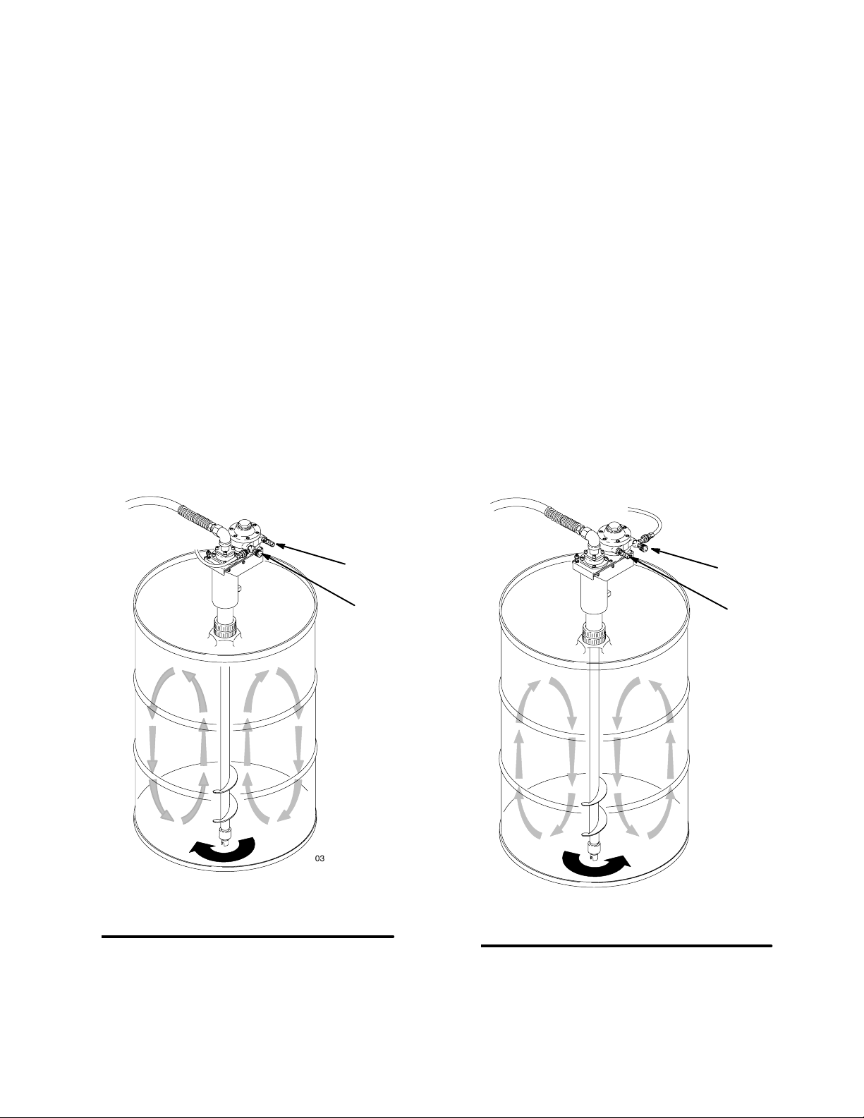
Standard Mixer, Model 236629
The standard mixer operates in a center-lift fluid rotation mode, which is preferred in most applications
because it minimizes fluid aeration. The helix rotates
counterclockwise and mixes fluid by lifting it up from
the bottom of the drum. See Fig. 1.
Standard mixer Model 236629 cannot reverse its helix
rotation.
16a
Oil-less Reversible Mixer, Model 236760
The oil-less reversible mixer operates the same as the
standard mixer, but it uses a non-lubricated air supply,
and the helix rotation can be reversed.
NOTE: Although the air motor can operate without oil,
motor life is increased when lubrication is provided.
To reverse the helix rotation on reversible mixer Model
236760, remove the air motor muffler (16a) and needle
valve (18), and switch the ports they are installed into.
See Fig. 2.
When the helix rotation is reversed, the mixer operates
in a pull-down fluid rotation mode, which can be better
for agitating fluids that are difficult to put into suspension. The helix rotates clockwise and mixes fluid by
pulling it down from the surface. See Fig. 2.
With clockwise (pull-down fluid rotation), care must be
used at high speeds to prevent cavitation, which could
be caused by air being drawn down to the siphon inlet.
18
Fig. 1
03401B
Model 236629
Standard (counterclockwise) Rotation
18
03401B
16a
03402B
Model 236760
Reversed (clockwise) Rotation
03402B
Fig. 2
4 308345
Page 5
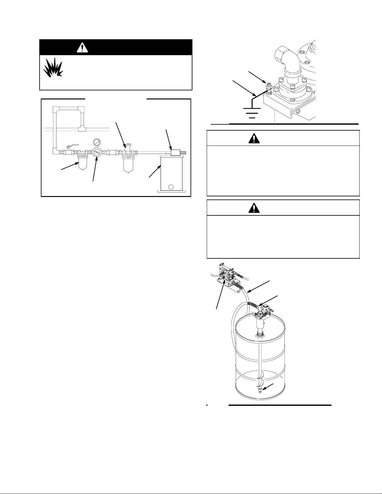
WARNING
Installation
FIRE AND EXPLOSION HAZARD
Always maintain a minimum of 1 in.
clearance between rotating agitator parts
and container to prevent sparks from contact.
Typical Installation
air line lubricator
agitator motor
air line filter
air regulator
and gauge
mix tank
(reference only)
Grounding Instructions
Proper grounding is an essential part of maintaining a
safe system.
To reduce the risk of static sparking, all electrically
conductive objects or devices in the spray area must
be properly grounded. Check your local electrical code
for detailed grounding instructions for your area and
type of equipment.
To ground the helix mixer, connect the ground wire
(H) to the grounding lug (J) on the collar. Connect the
grounding wire clamp to a true earth ground. See
Fig. 3.
To order a ground wire and clamp, order Part No.
222011.
J
H
Fig. 3
03024
CAUTION
The bearing nut (8) is made of acetal, which is not
compatible with some of the solvents used in paints
or coatings and is not compatible with acidic fluids.
Optional Rulon bearing nut Part No. 189660 is
available. Check your material data sheet and/or
supplier for compatibility.
CAUTION
To avoid damaging the mixer, do not mount the
pump (G) directly to the mixer outlet fitting (41).
Make sure the pump is properly supported, and
install a flexible suction hose (E) between the mixer
outlet fitting and the pump, as shown in Fig. 4.
E
41
G
Fig. 4
8
03428B
308345 5
Page 6

Installation
Air Line Accessories
The following air line accessories help to increase
motor life and ease of operation.
Air Line Filter
Air line filters remove harmful dirt and moisture from
the air supply. Order one of the following:
Part No. 106148: 3/8 npt(f) air line filter
Part No. 106149: 1/2 npt(f) air line filter
Air Line Lubricator (for Model 236629 only)
CAUTION
Not lubricating the air motor will cause air motor failure.
Downstream from the filter, install an air line lubricator
for automatic air motor lubrication. Set the lubricator
feed rate at 1 drop of oil per minute for high speed or
continuous duty usage. Do not overfeed oil or exhaust
air may become contaminated. To manually lubricate
the air motor, see Lubricating the Air Motor on page
11. Order one of the following:
Part No. 214847: 3/8 npt(f) air line lubricator
Part No. 214848: 1/2 npt(f) air line lubricator
Air Line Quick-Disconnect
Install an air line quick-disconnect (F) or ball valve at
the air inlet (D). See Fig. 5. Order one of the following:
Part No. 169969: 1/8 npt(m) air line quick-disconnect
Part No. 208536: 1/4 npt(f) air line quick-disconnect
Flush the Mixer Before Using It
To prevent fluid contamination, flush the mixer with
solvent that is compatible with the fluid to be mixed.
See Flushing Instructions on page 13.
6 308345
Page 7

Installation
Installing the Mixer
The mixer weighs 24 lb (11 kg). To manually lift it in
and out of the drum, grasp the housing (3), and guide
the helix tube (7) through the drum bung. See Fig. 5.
Accessory handle Part No. 189658 is available so you
can connect a lift hook to raise and lower the mixer or
hang the mixer to store it.
CAUTION
To avoid damaging the siphon tube, lower the mixer
to the drum bottom; do not drop it.
Do not install the mixer without the bearing nut (8) in
place. See Fig. 6 on page 9. If the bearing nut is not
installed, the siphon tube (4) and helix tube (7) will
rub against each other during operation and cause
damage. Replace the bearing nut if damaged or
worn.
1. Hold the mixer by the housing (3) or by the accessory handle, and lower the helix tube (7) through
the bung until the siphon tube rests on the bottom
of the drum.
5. When using the mixer suction feature, connect
a suction hose (E) between the mixer fluid outlet
fitting (41) and the pump. See Fig. 5. The hose
connector must have a 30 bevel to match the
fluid outlet fitting with an airtight seal. See Maxi-
mum Siphon Flow Rate on page 8.
When not using the siphon feature, plug the
fluid outlet fitting (41) to prevent excess fluid
evaporation.
The air motor exhaust can be piped out as follows:
Remove the air motor muffler (16a), and connect an
exhaust line to the exhaust port.
NOTE: Model 236629 has a1/4 npt(f) exhaust port.
Model 236760 has a 3/8 npt(f) exhaust port.
Model 236629 shown
E
41
16a
C
NOTE: The tube must rest on the bottom to evacuate the maximum amount of material from the
drum and to stabilize the mixer.
2. Make sure the gasket (46) is in place, screw the
bung adapter (44) into the bung, and tighten the
bung adapter. See Fig. 5.
3. Make sure the o-ring (20) in in place inside the
lock-ring (45), then tighten the lock-ring (45).
CAUTION
To keep the helix tube pointed straight down, make
sure the bung adapter (44) and lock ring (45) are
tight.
4. Position the air motor so the air line (C) can be
attached to the inlet (D) on the needle valve without obstructing any other system components.
3
D
F
45
20
44
7
46
03025B
Fig. 5
308345 7
Page 8

Operation
WARNING
MOVING PARTS HAZARD
To reduce the risk of serious injury,
including cuts, amputation of fingers,
and splashing in the eyes or on the skin:
Always shut off the mixer and disconnect the air
line before you check or repair the mixer.
Maximum Siphon Flow Rate
The volume of fluid that can be siphoned through the
mixer inlet is determined by the viscosity of the fluid.
The maximum flow rate is approximately 12 gpm
(45 lpm) with 100-centipoise fluid.
The maximum flow rate is approximately 1.2 gpm
(4.5 lpm) with much heavier 1000-centipoise fluid.
To prevent pump cavitation, avoid flow rates higher
than these. Check the fluid periodically for signs of
cavitation.
Operating the Mixer
See Fig. 6
CAUTION
The bearing nut (8) helps prevent excessive fluid
flow between the siphon tube (4) and helix tube (7),
but it is not intended to be a complete seal. Fluids
can pass through the bearing nut into the gap between the two tubes. Before you change colors or
coatings or store the mixer, clean the tubes as
instructed on page 10.
NOTE: Thoroughly agitate the fluid before you use the
suction feature. Agitating maximizes fluid quality and
helps avoid solids getting drawn into the siphon tube
and clogging it. A Strainer Inlet Kit 236984 is available to help prevent thick sediment from being forced
into the siphon inlet.
CAUTION
Air Requirements
For continuous use, the 0.75 HP air motor typically
requires 2.5 scfm (0.071 m/min.) of air at 400 rpm or
5.7 scfm (0.162 m3/min.) of air at 800 rpm.
Nitrogen Charging the Drum
CAUTION
If you are using nitrogen to charge the drum, use a
maximum of 0.25 psi (1.7 kPa, 0.02 bar). Such low
pressure requires special regulation equipment. Use
a passive, non-pressurized system when possible.
Higher pressure could push fluid through the shaft
seal (21) and into the top bearings (11), damaging
them. See the Parts Drawing on page 16.
Do not operate the mixer at a high speed for a long
period of time. Excessive mixer speed can cause the
fluid to foam and can cause vibration and increased
wear on parts and damage to the drum bung. Only
agitate the fluid fast enough to maintain even mixing.
You can view fluid movement through the 0.75-in.
port on the drum cover.
NOTE: If you install an air shut-off valve, the same
mixer speed is set each time it is turned on without
requiring repeated needle valve adjustments. Order
one of the following air shut-off valves:
Part No. 208390: 1/4 npt(m) x 1/4 npt(m)
Part No. 208391: 3/8 npt(m) x 3/8 npt(f)
Part No. 208392: 3/8 npt(f) x 1/4 npt(m)
Part No. 208393: 3/8 npt(m) x 3/8 npt(m)
You can also use an air line quick-disconnect (F) as a
shut-off. See Fig. 5. See Air Line Quick-Disconnect
on page 6.
8 308345
Page 9

Operation
1. Turn on the air supply to start the mixer. Regulate
the helix speed with the needle valve (18).
2. Operate the mixer continuously when supplying
paints or other fluids to the system.
Model 236629 shown
7
4
F
8
18
Shutting Down
1. To stop the mixer, close the needle valve (18), or
disconnect the quick-disconnect (F), or close the
air valve in the air supply line.
2. If you remove the mixer from the drum, remove
the bearing nut (8), and hang or tilt the mixer
upright over a container to allow it to drain. Accessory handle Part No. 189658 is available so you
can connect a lift hook to raise and lower the mixer
or hang the mixer to store it.
CAUTION
Keep the mixer upright. Do not lay it on its side or
upside down, because fluid might flow into the beltdrive area.
If you use the accessory mixer handle, make sure
the mixer is loosened from the drum before you raise
it with a lift. The handle will not support the weight of
the drum.
Fig. 6
03400B
Do not let fluid from dry in the fluid tubes. See Clean-
ing the Fluid Tubes on page 10.
308345 9
Page 10

Maintenance
Prolonging the Life of the Bearing Nut
CAUTION
Use a compatible solvent to clean parts. The bearing
nut (8) is made of acetal, which is not compatible
with acidic fluids. Check your material data sheet
and/or supplier for compatibility. Avoid getting any
solvent on the air motor belt.
Replace the bearing nut (8) if it is damaged or
worn.
Do not allow fluids to dry out in the fluid section.
Dry fluid will adhere to the bearing nut (8) and could
destroy it the next time you start the mixer. Flush
the fluid section before you change colors or coatings or store the mixer.
Do not operate the mixer without fluid in the drum
as this can cause excessive bearing nut (8) wear.
5. Apply PTFE spray lubricant to the siphon tube (4)
inlet end only. Install the siphon tube through the
top of the mixer housing (3).
6. Install the two socket-head screws (24) and lockwashers (25) into the top of the siphon cover (6).
Torque the screws oppositely and evenly to 60 to
70 in-lbs (6.8 to 7.9 Nm).
7. Apply PTFE spray lubricant to the inside lip of the
bearing nut (8), and tighten it onto the helix
tube (7).
Model 236629 shown
24
1
16a
41
2
24
5
18
25
6
4
33
Cleaning the Fluid Tubes
To prevent fluid from drying on the tubes and interfering with helix rotation, clean the siphon tube (4) and
helix tube (7) when you change colors or coatings and
when the mixer is removed from the drum long enough
for the fluid to dry. Also, clean the fluid tubes for periodic maintenance as follows:
1. Remove the bearing nut (8). See Fig. 7.
2. Remove the two diagonal socket-head screws (24)
and lockwashers (25) protruding from the top of
the siphon cover (6).
3. Remove the siphon tube (4) as follows:
a. Rest the mixer on its side on the drive belt
housing so the inlet is lower than the outlet.
This orientation prevents fluid from running
into the bearing and drive belt area.
b. Pull up on the fluid outlet fitting (41) to remove
the siphon tube (4).
4. Clean the siphon tube (4), helix tube (7), and
bearing nut (8). The inside diameter of the tubes
can be cleaned by pulling a solvent-soaked rag
through them.
NOTE: Always after you mix or pump catalyzed mate-
rials that could set up between the tubes without air,
remove the siphon tube, and clean both tubes.
10 308345
4
Torque oppositely and evenly to 60 to 70 in-lbs (6.8 to 7.9 Nm).
1
Torque oppositely and evenly to 80 to 100 in-lbs (9 to 11.3 Nm).
2
Apply PTFE spray lubricant to inside lip of bearing nut before
3
you install it.
Apply PTFE spray lubricant to the siphon tube (4) inlet end
4
before you install it.
7
3
8
Fig. 7
3
03403B
03403B
Page 11

Maintenance
Lubricating the Air Motor
(Model 236629 Only)
CAUTION
Not lubricating the air motor will cause air motor failure.
If an air line lubricator is not installed, the air motor
must be manually lubricated every 8 hours. Lubricate
the agitator air motor by placing 10–20 drops of SAE
#10 light oil in the motor’s air inlet. Run the agitator for
about 30 seconds.
Cleaning the Air Intake Check Valve
The air intake check valve (33) allows make-up air to
enter the closed drum as fluid is drawn out through the
mixer outlet port. See Fig. 7. The air intake check
valve should be inspected and cleaned every 2000
operating hours or when there are any signs of the
drum beginning to collapse as fluid is drawn out.
Pump priming problems can indicate a plugged air
intake check valve. Paint overspray in the air can be
drawn into the valve and cause the ball to stick in the
closed position.
To clean the air intake check valve
1. Remove the seat (33) and ball (34). See the Parts
Drawing on page 16.
2. Clean the parts with compatible solvent, and
reassemble the valve.
3. Insert the ball (34), and tighten seat (33) until just snug.
NOTE: The seat should not be flush with
the elbow (32). Installing the seat too
tightly could jam the ball against the seat.
Correcting a Bad Suction Line Seal
Air getting pulled into the suction line makes the pump
inefficient. This can happen for the following reasons:
Cavitation is occurring, because the pump or helix
is going too fast.
Siphon hose connection is leaking.
Nylon rings (22) are not sealing. See Fig. 8.
To correct the problem (see Fig. 8)
1. Torque the four socket-head screws (24) in the
siphon fitting (5) oppositely and evenly to 80 to 100
in-lbs (9.0 to 11.3 Nm).
NOTE: If Step 1 does not correct the problem, do
Steps 2 through 5.
2. Replace the rings (22). Make sure the outer lips
face up, as shown in Fig. 8.
3. Insert the inlet tube (4) into the bottom of the
siphon fitting (5).
4. Tap the bottom of the inlet tube (4) to make sure
the tube passes through the rings (22) and seats
on the siphon fitting (5).
5. Torque the four socket-head screws (24) in the
siphon fitting (5) oppositely and evenly to 80 to 100
in-lbs (9.0 to 11.3 Nm).
308345 11
Page 12

Torque screws oppositely and evenly to
1
80 to 100 in-lbs (9.0 to 11.3 Nm).
2
Install with outer lips facing up.
Maintenance
5
24
1
22
2
4
Fig. 8
TI0302
12 308345
Page 13

Service
WARNING
MOVING PARTS HAZARD
To reduce the risk of serious injury,
including cuts, amputation of fingers,
and splashing in the eyes or on the skin
Always shut off the mixer and disconnect the air
line before you check or repair the mixer.
Wear eye protection.
WARNING
FIRE AND EXPLOSION HAZARD
To prevent an explosive hazard, in which
injury and/or property damage can result
Do not operate the air motor with combustible
gases.
Do not use kerosene or other flammable
solvents for flushing.
WARNING
HAZARDOUS FLUIDS
Keep your face away from the exhaust
port. Foreign material exiting the air
motor can be hazardous.
Flushing Instructions
If the motor is sluggish or inefficient, flush it with nonflammable solvent in a well-ventilated area.
The recommended solvent for air motors and lubricated pumps is Gast flushing solvent (Part No.
AH255 or AH255A) or Inhibisol Safety Solvent.
1. Disconnect the air line and muffler.
2. Dump or spray several teaspoons of solvent
directly into the motor.
3. Rotate the shaft by hand in both directions for a
few minutes.
4. Reconnect the air line, and slowly increase air
pressure until there is no trace of solvent in the
exhaust air.
5. Re-lubricate the motor with a squirt of light-weight
oil in the chamber.
Servicing Guidelines
NOTE: If the motor does not operate properly after
flushing, order and install the repair kit for your air
motor. The instructions for servicing the air motor are
included with the kit. See page 17 to order the kit.
If the mixer requires more than installation of a
service kit, it is usually quickest and easiest to send
it to the Graco distributor for repair or replacement.
If the vanes need replacing or foreign material is
present in the motor chamber, an experienced
mechanic may remove the end plate opposite the
drive shaft end. Do not pry with a screwdriver. It will
dent the surface of the plate and body and cause
leaks. Use a puller tool, which will remove the end
plate while maintaining the position of the shaft.
New vanes should have the edges with cut corners
(or the notched edges, if the vanes are reversible)
pointing toward the bottom of the vane slot.
308345 13
Page 14

Service
25
24
Detail A
1
6
14a
41
14
Removing the Siphon and Helix Tubes
1. Remove the bearing nut (8). See Fig. 9.
2. Remove the two diagonal socket-head screws (24)
and lockwashers (25) protruding from the top of
the siphon cover (6).
3. Remove the siphon tube (4) as follows:
a. Rest the mixer on its side on the drive belt
housing so the inlet is lower than the outlet.
This orientation prevents fluid from running
into the bearing and drive belt area.
b. Pull up on the fluid outlet fitting (41) to remove
the siphon tube (4).
3
B
4. Remove the three hex-head screws (14a) from the
bushing (14), and install the screws into the bushing’s threaded holes as shown in Detail A of Fig.
9. Tighten the screws evenly to loosen the bushing
from the helix tube (7).
5. Pull the helix tube (7) through the bottom of the
mixer housing (3).
4
3
3
35
14
7 Ref
Detail B
Model 236629 shown
Torque oppositely and evenly to 60 to 70 in-lb (6.8 to 7.9 Nm).
1
Apply PTFE spray lubricant to inside lip of bearing nut before
2
you install it.
Apply PTFE spray lubricant to siphon tube (4) inlet end and to
3
top 6 in. (150 mm) of helix tube before you install them.
Fig. 9
14 308345
7
8
06240C
Removing the Drive Belt
NOTE: Replace the drive belt (15) if it is cracked or
worn.
WARNING
To avoid static electricity buildup and possible
sparking, which could cause fire and explosion,
replace the drive belt with a genuine ESD rated
and marked belt only (Graco Part No. 112552).
2
1. Remove the siphon tube (4) and helix tube (7) as
instructed above.
2. Remove the eight screws (27) and the drive belt
cover (2). See Fig. 10.
3. Remove the three hex-head screws (14a) and the
bushing (14).
4. Slide the drive belt (15) over the smaller pulley
(12). Then remove the larger pulley (13) and the
drive belt (15) as shown in Fig. 10.
Page 15

Service
Model 236629 shown
1
14a
14
13
2
With helix tube (7) flush with top of bushing (14), torque the
1
screws oppositely and evenly to 55 to 60 in-lbs (6.2 to 6.8 Nm).
2
Replace with a genuine ESD rated and marked belt only.
Fig. 10
12 22715
03027B
Assembling the Mixer
1. Make sure the spacer (10) is in place (see Parts
Drawing on page 16). With its larger-I.D. taper
facing up, install the larger pulley (13) and the
drive belt (15) through the mixer housing. See
Fig. 10.
2. Slide the other end of the drive belt over the
smaller pulley (12). The drive belt should not be
tight after it is installed. Make sure the pulleys are
aligned, then secure the small pulley (12) by
tightening its setscrew. Torque setscrew to
45 to 55 in–lbs (5.1 to 6.2 Nm).
3. Place the bushing (14) into the larger pulley (13).
4. Install the screws (14a) in the non-threaded holes
in the bushing (14); do not tighten the screws yet.
5. Place the installation tool (B) on the end of the
helix tube. See Fig. 9.
NOTE: The installation tool (B) is included with
Shaft Seal Kit 236762.
CAUTION
Use the installation tool (B) to insert the helix tube (7)
through the shaft seal (21) without damaging the seal
lip. See Fig. 9. See the Parts Drawing on page 16
for the location of the seal.
6. Apply PTFE spray lubricant to the top 6 in.
(150 mm) of the helix tube (7). While holding the
pulley (13) down, push the helix tube and tool (B)
up through the bottom of the mixer housing (3)
until the tube is flush with the top of the bushing
(14). Then remove the installation tool.
Wedge a screwdriver blade into the gap of the
bushing (14) to spread the bushing while inserting
tube (7).
7. Torque the three hex-head screws (14a) oppositely
and evenly to 55 to 60 in-lbs (6.2 to 6.8 Nm). See
Fig. 10.
8. Install the thrust washer (35) flush to the bushing
(14) as shown in Detail B of Fig. 9.
9. Secure the drive belt cover (2) with the eight
screws (27).
10. Apply PTFE spray lubricant to the siphon tube (4)
inlet end only. Install the siphon tube through the
top of the mixer housing (3). See Fig. 9.
11. Install the two socket-head screws (24) and lockwashers (25) into the top of the siphon cover (6).
Torque the screws oppositely and evenly to 60 to
70 in-lbs (6.8 to 7.9 Nm).
NOTE: The helix tube (7) should move up and
down about 0.05 inch (1.3 mm). If it does not, the
bearings (11) are not fully seated. Push the bearings in until they are fully seated. See the Parts
Drawing on page 16 for the location of the bearings.
12. Apply PTFE spray lubricant to the inside lip of the
bearing nut (8), and tighten it onto the helix
tube (7).
308345 15
Page 16

Parts Drawing
Press into place; lips face down.
1
Apply high-strength thread sealant
2
to threads.
10
25
28
31
30
35
4
9
25
11
27
29
24
41
3
5
3
24
39
13
22
6
32
3
34
4
16 or 17
51
3
30
16a
3
26
3
7
1
18
See Detail
50
45
20
33
44
3
2
27
46
7
14a
12a
12
5
Apply anaerobic PTFE pipe sealant
3
to threads.
With helix tube (7) flush with top of
4
bushing (14), torque oppositely and
evenly to 55 to 60 in-lbs (6.2 to 6.8
Nm).
Tighten after you align pulleys
5
(12 and 13). Torque setscrew to
45 to 55 in–lbs (5.1 to 6.2 Nm).
6
Drive belt must not be tight after it is
installed.
7
Bend washer tab up to lock.
Apply PTFE spray lubricant to
8
inside lip of bearing nut before you
install it.
Torque oppositely and evenly to 80
9
to 100 in-lbs (9 to 11.3 Nm).
Torque oppositely and evenly to 60 to
10
70 in-lbs (6.8 to 7.9 Nm).
Apply PTFE spray lubricant to siphon
11
tube (4) inlet end and to top 6 in.
(150 mm) of helix tube (7) before you
install them.
Install flush with top of nut (8), and
12
torque to 40 to 45 in-lb (4.5 to 5.1
Nm).
Install with outer lips facing up. See
13
Fig. 8 on page 12.
14
13
10
2
11
9
11
1
21
16 308345
15
6
11
Needle Valve (Ref. No. 18) Detail
18e
18f
18d
51
3
18a
18b
18c
Includes items 18a to 18e
8
8
56
12
TI0301B
0911B
Page 17

Parts List
Model 236629 Standard Mixer
Includes items 1 to 16 and 18 to 50, 57–58
Model 236760 Oil-less Reversible Mixer
Includes items 1 to 15 and 17 to 58
Ref.
No. Part No. Description Qty.
1 236720 BRACKET 1
2 189648 COVER, belt drive 1
3 189649 HOUSING, mixer 1
4 189651 TUBE, siphon 1
5 189653 FITTING, siphon 1
6 189654 COVER, siphon 1
7 236719 TUBE, helix 1
8 189655 NUT, bearing; acetal AF 1
9 189656 SPACER, bearing 1
10 189657 SPACER, pulley 1
11 112548 BEARING, ball 2
12 112549 PULLEY (small), drive belt
Includes item 12a 1
12a – SETSCREW, pulley;
1/4 x 20 x 3/16 in.
(not a replacement part) 1
13 112550 PULLEY (large), drive belt 1
14 112551 BUSHING, QD taper lock;
includes items 14a 1
14a – SCREW, hex head; #10–24 x 1 in.
(not a replacement part) 3
15 112552 BELT, drive; ESD rated / marked 1
16* 101140 AIR MOTOR, standard; 0.75 HP
Model 236629 only
Includes item 16a 1
16a 113779 MUFFLER, exhaust; 1/4 npt 1
17** 112723 AIR MOTOR, reversible, oil-less;
0.75 HP Model 236760 only;
Includes item 16a 1
18 206264 VALVE, needle
Includes items 18a to 18f 1
18a 166529 .VALVE, needle 1
18b 166532 .NUT, packing 1
18c 164698 .KNOB, adjusting 1
18d 157628 .O–RING, packing 1
18e 165722 .BODY, valve 1
18f 166531 .WASHER 1
20 112553 O-RING; PTFE 1
21 112555 SEAL, shaft; graphite-filled PTFE 1
22 195045 RING, seal, tube support; Nylon 3
24 112556 SCREW, socket-head; M6 x 16 8
25 108050 LOCKWASHER, spring; M6 8
Ref.
No. Part No. Description Qty.
26 112557 SCREW, set; M6 1
27 106084 SCREW, pan-head; M5 x 10 10
28 104029 LUG, grounding 1
29 104582 WASHER, tab 1
30 105332 LOCK NUT, hex 3
31 100718 LOCKWASHER; #10 1
32 100839 ELBOW, street; 1/8 npt 1
33 189659 SEAT, check valve 1
34 105691 BALL; 1/4 in. diameter; SST 1
35 189662 WASHER, thrust 1
39 189527 LABEL, warning 1
41 112572 UNION, swivel; 90
44 178575 ADAPTER, bung 1
45 178576 RETAINER, o-ring 1
46 106537 GASKET; polyethylene 1
50 189650 TUBE, housing 1
51 159841 ADAPTER;
3/8 npt(m) x 1/4 npt(f);
Model 236760 only 2
56 110980 CLAMP, hose
Model 236760 only 1
57 15A722 LABEL, warning 1
58 16A614 LABEL, warning 1
* A repair kit is available. Order Repair Kit 207335 for
standard air motor (Part No. 101140).
** A repair kit is available. Order Repair Kit 236996 for
reversible oil-less air motor (Part No. 112723). You
must also order two adapters (Part No. 159841), to
adapt the needle valve and muffler.
This part is included in Repair Kit 236762, which
may be purchased separately. The kit also includes
an installation tool, which is needed to insert the
helix tube through the shaft seal without damaging
the seal lip.
An optional Rulon bearing nut is available. Order
Part No. 189660.
Keep these spare parts on hand to reduce down
time.
Replacement Danger and Warning labels, tags, and
cards are available at no cost.
308345 17
Page 18

Technical Data
Maximum working pressure 100 psi (0.7 MPa, 7 bar). . . . . . . . . . . . . . . . . . . . . . . . . . . . . . . . . . . . . . . . . . . . . . . . . . . . . . .
Maximum recommended helix speed 800 rpm. . . . . . . . . . . . . . . . . . . . . . . . . . . . . . . . . . . . . . . . . . . . . . . . . . . . . . . . . . . . .
Maximum siphon flow rate
with 100 centipoise material approximately 12 gpm (45 lpm). . . . . . . . . . . . . . . . . . . . . . . . . . . . . . . . . . . . . . . . . . . . .
with 1000 centipoise material approximately 1.2 gpm (4.5 lpm). . . . . . . . . . . . . . . . . . . . . . . . . . . . . . . . . . . . . . . . . . . .
Air consumption
at 400 rpm 2.5 scfm (0.071 m/min). . . . . . . . . . . . . . . . . . . . . . . . . . . . . . . . . . . . . . . . . . . . . . . . . . . . . . . . . . . . . . . . . . .
at 800 rpm 5.7 scfm (0.162 m3/min). . . . . . . . . . . . . . . . . . . . . . . . . . . . . . . . . . . . . . . . . . . . . . . . . . . . . . . . . . . . . . . . . . .
Noise level at 400 to 800 rpm (tested to CAGI-PNEUROP–1969) < 70 dBA. . . . . . . . . . . . . . . . . . . . . . . . . . . . . . . . . . .
Weight 24 lb (11 kg). . . . . . . . . . . . . . . . . . . . . . . . . . . . . . . . . . . . . . . . . . . . . . . . . . . . . . . . . . . . . . . . . . . . . . . . . . . . . . . . . . .
Wetted parts 304 and 316 stainless steel, graphite-filled PTFE, acetal AF, Rulon LR. . . . . . . . . . . . . . . . . . . . . . . . . .
External parts that may come in contact with fluid
Bung adapter (Ref. No. 44) carbon steel. . . . . . . . . . . . . . . . . . . . . . . . . . . . . . . . . . . . . . . . . . . . . . . . . . . . . . . . . . . . . .
Air check valve elbow (Ref. No. 32) carbon steel. . . . . . . . . . . . . . . . . . . . . . . . . . . . . . . . . . . . . . . . . . . . . . . . . . . . . . .
Housing (Ref. No. 3) aluminum. . . . . . . . . . . . . . . . . . . . . . . . . . . . . . . . . . . . . . . . . . . . . . . . . . . . . . . . . . . . . . . . . . . . . . .
Rulon is a registered trademark of Dixon, a division of Furon.
Gast is a registered trademark of Gast Manufacturing.
Inhibisol is a registered trademark of Penetone Corp.
18 308345
Page 19

Dimensions
3/4–14 npt(f)
fluid outlet
7.4 in.
(18.8 cm)
1/8 npt(f)
air inlet
NOTE: The bung adapter
adjusts the depth of the
mixer to a minimum of 32 in.
(81.3 cm) and a maximum of
35-1/8 in. (89.2 cm).
32 in. (81.3 cm) minimum
35-1/8 in. (89.2 cm) maximum
48.6 in.
(123.4 cm)
2 npt
bung adapter
03023B
308345 19
Page 20

Graco Standard Warranty
Graco warrants all equipment manufactured by Graco and bearing its name to be free from defects in material and workmanship on the
date of sale to the original purchaser for use. With the exception of any special, extended, or limited warranty published by Graco,
Graco will, for a period of twelve months from the date of sale, repair or replace any part of the equipment determined by Graco to be
defective. This warranty applies only when the equipment is installed, operated and maintained in accordance with Graco’s written
recommendations.
This warranty does not cover, and Graco shall not be liable for general wear and tear, or any malfunction, damage or wear caused by
faulty installation, misapplication, abrasion, corrosion, inadequate or improper maintenance, negligence, accident, tampering, or substitution of non–Graco component parts. Nor shall Graco be liable for malfunction, damage or wear caused by the incompatibility of
Graco equipment with structures, accessories, equipment or materials not supplied by Graco, or the improper design, manufacture,
installation, operation or maintenance of structures, accessories, equipment or materials not supplied by Graco.
This warranty is conditioned upon the prepaid return of the equipment claimed to be defective to an authorized Graco distributor for
verification of the claimed defect. If the claimed defect is verified, Graco will repair or replace free of charge any defective parts. The
equipment will be returned to the original purchaser transportation prepaid. If inspection of the equipment does not disclose any defect
in material or workmanship, repairs will be made at a reasonable charge, which charges may include the costs of parts, labor, and
transportation.
THIS WARRANTY IS EXCLUSIVE, AND IS IN LIEU OF ANY OTHER WARRANTIES, EXPRESS OR IMPLIED, INCLUDING BUT
NOT LIMITED TO WARRANTY OF MERCHANTABILITY OR WARRANTY OF FITNESS FOR A PARTICULAR PURPOSE.
Graco’s sole obligation and buyer’s sole remedy for any breach of warranty shall be as set forth above. The buyer agrees that no other
remedy (including, but not limited to, incidental or consequential damages for lost profits, lost sales, injury to person or property, or any
other incidental or consequential loss) shall be available. Any action for breach of warranty must be brought within two (2) years of the
date of sale.
Graco makes no warranty, and disclaims all implied warranties of merchantability and fitness for a particular purpose in connection
with accessories, equipment, materials or components sold but not manufactured by Graco. These items sold, but not manufactured
by Graco (such as electric motors, switches, hose, etc.), are subject to the warranty, if any, of their manufacturer. Graco will provide
purchaser with reasonable assistance in making any claim for breach of these warranties.
In no event will Graco be liable for indirect, incidental, special or consequential damages resulting from Graco supplying equipment
hereunder, or the furnishing, performance, or use of any products or other goods sold hereto, whether due to a breach of contract,
breach of warranty, the negligence of Graco, or otherwise.
FOR GRACO CANADA CUSTOMERS
The parties acknowledge that they have required that the present document, as well as all documents, notices and legal proceedings
entered into, given or instituted pursuant hereto or relating directly or indirectly hereto, be drawn up in English. Les parties reconnaissent avoir convenu que la rédaction du présente document sera en Anglais, ainsi que tous documents, avis et procédures judiciaires
exécutés, donnés ou intentés à la suite de ou en rapport, directement ou indirectement, avec les procedures concernées.
Graco Information
For the latest information about Graco products, visit www.graco.com.
For patent information, see www.graco.com/patents.
TO PLACE AN ORDER, contact your Graco distributor, or call to identify the nearest distributor:
Phone: 612–623–6921 or Toll Free: 1–800–328–0211 Fax: 612–378–3505
All written and visual data contained in this document reflect the latest product information available at the time of publication.
Graco reserves the right to make changes at any time without notice.
20 308345
Original instructions. This manual contains English. MM 308345
International Offices: Belgium, China, Japan, Korea
GRACO INC. AND SUBSIDIARIES
Copyright 1994, Graco Inc. All Graco manufacturing locations are registered to ISO 9001.
Graco Headquarters: Minneapolis
P.O. BOX 1441 MINNEAPOLIS, MN 55440-1441 USA
www.graco.com
Revision P – December 2012
 Loading...