

Page 1
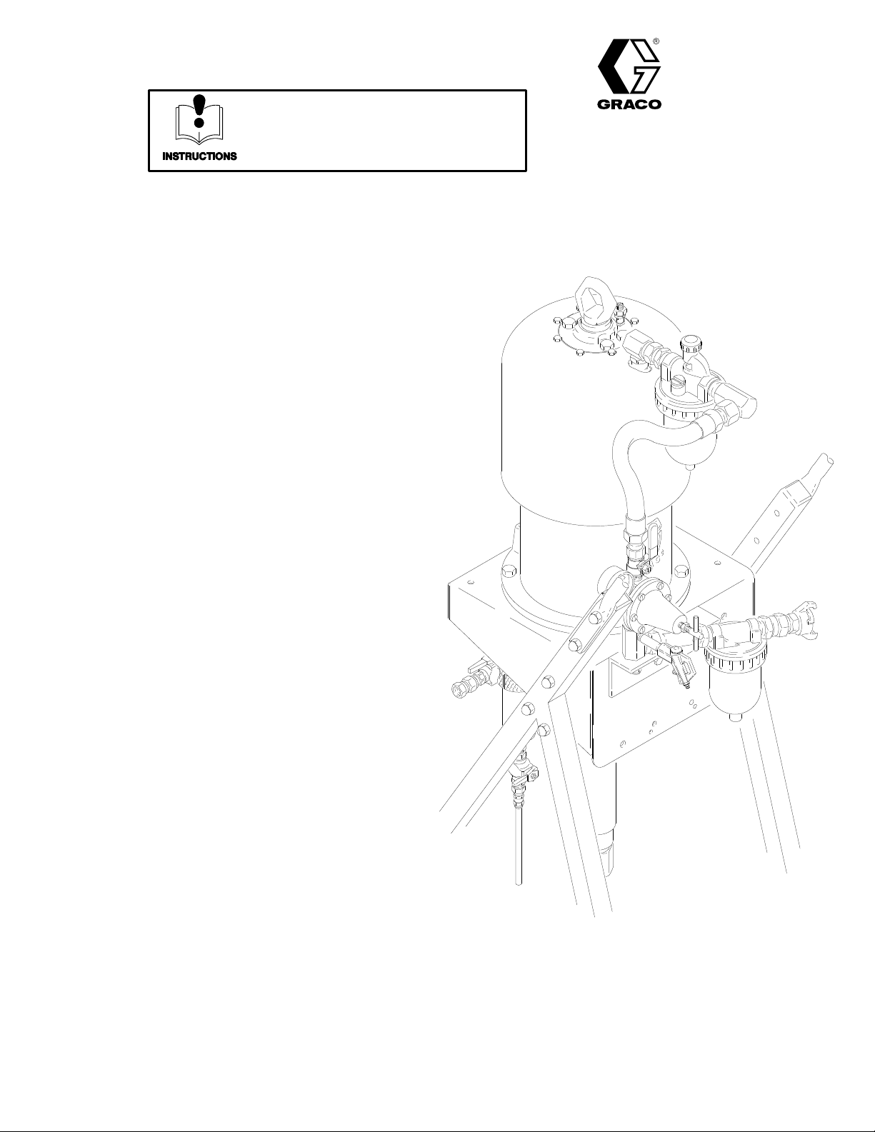
INSTRUCTIONS–P
This manual contains important
warnings and information.
READ AND RETAIN FOR REFERENCE
ARTS LIST
308–322
Rev.
A
Upgrade
For
45:1 Ratio King Sprayer 965–333
(see manual 307–666)
4050 psi (280 bar) Maximum Working Pressure
90 psi (6.3 bar) Maximum Air Inlet Pressure
For
63:1 Ratio King Sprayer 965–271
(see manual 307–666)
5000 psi (345 bar) Maximum Working Pressure
79 psi (5.4 bar) Maximum Air Inlet Pressure
Kit 949–204
GRACO INC. P.O. BOX 1441
COPYRIGHT
MINNEAPOLIS, MN
1993, GRACO INC.
55440–1441
Page 2
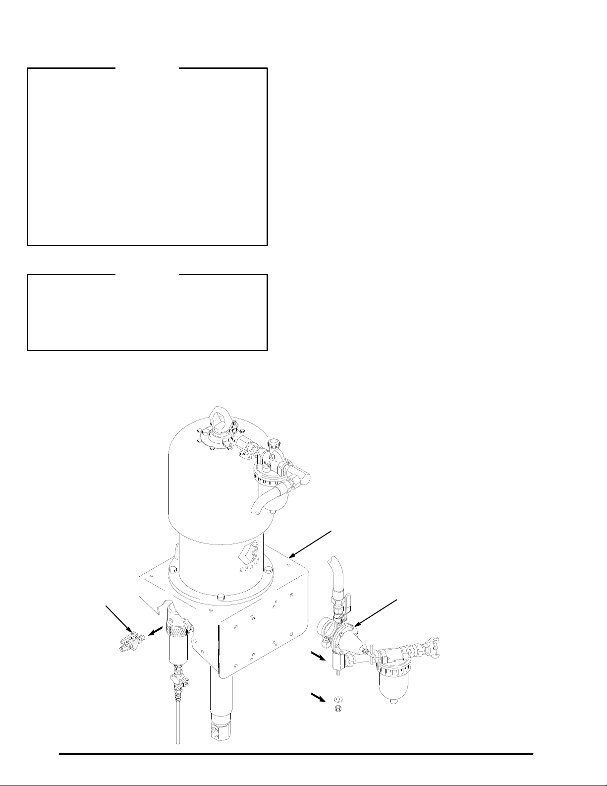
Installation
WARNING
Separate manuals are supplied with some compo
nents of your sprayer
instruction manuals before operating.
Never exceed the
sure
and
Maximum Air Input Pressure
sprayers, given in the Technical Data
cover
. Never exceed the maximum working pres
sure of the lowest rated component in your system.
Be sure that all fluids and solvents used are chemi
cally compatible with the wetted parts listed in your
separate component manuals.
If you are installing the kit on a previously operated
sprayer
directed in the
pump manual 307–013 (for 45:1 King Pump) or
307–663 (for 63:1 King Pump).
, be sure to relieve all system pressure, as
. Read and understand all
Maximum Fluid Working Pres
for these
on the back
WARNING
Pressure Relief Procedure
-
-
given in
2.
Steps a–c apply to Model 965–333 only
-
-
parts are already installed on Model 965–271.
a.
Remove the 1/4 npt and 1/8 npt pipe plugs
from the 90 air manifold (A). See Fig. 2.
b.
Screw the long nipple (10) into the 1/4 npt
port. Screw the air blow gun (1
ple. See the T
c.
Screw the nipple (12) into the 1/8 npt port.
Screw the quick disconnect coupler (13) onto
the nipple. See the T
3.
Orient the regulator bracket (6) as shown in Fig. 2
and align its holes with the two centermost holes in
the cart shelf (C). Apply thread adhesive (3) to the
two screws (7). Install the screws (7), washers (8)
and nuts (9) as shown. T
Apply thread adhesive (3) to the stud (S) of the air
4.
regulator kit (R). Install the stud in the hole of the
bracket (6) and secure with the washer (1) and nut
(2). Do not use the old nut. T
op V
iew in Fig. 2.
op V
iew in Fig. 2.
ighten securely
ighten securely
. These
1) onto the nip
.
.
-
1.
Remove and discard the nut and washer holding
the air regulator kit (R) to the cart shelf (C). See
Fig. 1.
V
Remove the existing ball valve (V) from the fluid
5.
filter (F). See Fig. 1. Install the new valve (5). See
Fig. 2. Screw the rigid end of the union (4) onto
the valve.
C
R
Fig. 1
02249
Page 3

Parts
Ref.
No. Part No. Description Qty.
1 100–133 WASHER, spring lock; 3/8” 1
2 101–566 NUT
3 102–969
4 156–173 UNION, swivel;
5 210–658 VAL
6 625–710 BRACKET
7 100–450 SCREW
8 100–527 WASHER 2
9 595–757 NUT
10* 100–124
11* 208–625 GUN, air blow 1
12* 151–519
13* 208–536 COUPLER, quick disconnect;
*
These parts are included for installation on Model
965–333. These parts are already installed on Model
965–271.
, nylock; 3/8–16
ADHESIVE, thread
3/8 npt(f) x 3/8 npsm(f); carbon steel
VE, ball; 3/8 npt(mbe)
, regulator
, cap, hex hd;
5/16–18 x 1” (25 mm)
, stop
NIPPLE; 1/4 npt; 2–1/2” (64 mm)
NIPPLE, reducer; 1/4 npt x 1/8 npt
1/4 npt(f)
, King
1
1
1
1
1
2
Top View
*12
13*
A
2
1
1
1
*10
11*
A
NOTE:
Shaded parts are included in kit.
9
8
R
6
5
4
Fig. 2
3
A
7
S
1
C
2
Page 4

Technical
Data
Ratio
.
. . . . . . . . . . . . . . . . . . . . . . . . . . . . . . . . . . . . . . . . . . . . . . . . . . . . . . .
Maximum fluid working pressure
Maximum air input pressure
W
etted parts See separate component manuals
The
Graco Warranty and Disclaimers
.
. . . . . . . . . . . . . . . . . . . . . . . . . . . . . . . . . . . .
.
. . . . . . . . . . . . . . . . . . . .
.
. . . . . . . . . . . . . . . . . . . . . . . . . . .
Model 965–333:
Model
965–271:
Model 965–333:
Model
Model
Model
4050 psi (280 bar)
5000 psi (345 bar)
965–271:
90 psi (6.3 bar)
79 psi (5.4 bar)
965–333:
965–271:
45:1
63:1
WARRANTY
Graco
warrants all equipment manufactured by it and bearing its name to be free from defects in material and workman
ship on the date of sale by an authorized Graco distributor to the
for
breach of this warranty
, Graco will, for
a period of twelve months from the date of sale, repair or replace any part of the
equipment proven defective. This warranty applies only when the equipment is installed, operated
accordance with Graco’
This
warranty does not cover
misapplication, abrasion, corrosion, inadequate or improper maintenance, negligence, accident, tampering, or
lation,
substitution
of non–Graco component parts. Nor shall Graco be liable for malfunction, damage or wear caused by the
s written recommendations.
, and Graco shall not be liable for
incompatibility with Graco equipment of structures, accessories,
improper
als
This
design, manufacture, installation, operation or maintenance of
not supplied by Graco.
warranty is conditioned upon the prepaid return of the equipment claimed to be defective to an authorized Graco
original
purchaser for use. As purchaser’s sole remedy
and maintained in
, any malfunction, damage or wear caused by faulty instal
equipment or materials not supplied by Graco, or the
structures, accessories, equipment or materi
distributor for verification of the claim. If the claimed defect is verified, Graco will repair or replace free of charge any
defective parts. The equipment will be returned to the original purchaser transportation prepaid. If inspection of the
does
equipment
charges
may include the costs of parts, labor and transportation.
not disclose any defect in material or workmanship, repairs will be made at a reasonable charge, which
-
-
-
DISCLAIMERS AND LIMIT
THE
TERMS OF THIS W
RANTIES
POSE,
EVERY
NO
BE
(EXPRESS OR IMPLIED), INCLUDING W
AND OF ANY NON–CONTRACTUAL LIABILITIES, INCLUDING PRODUCT LIABILITIES, BASED
FORM OF
CASE SHALL GRACO’S LIABILITY EXCEED THE AMOUNT OF THE PURCHASE PRICE. ANY ACTION FOR BREACH OF W
BROUGHT WITHIN TWO (2) YEARS OF THE DA
EQUIPMENT
GRACO
MAKES NO W
PURPOSE,
These
WITH RESPECT T
items sold, but not manufactured by Graco (such as electric motor
ARRANTY CONSTITUTE
LIABILITY FOR DIRECT
NOT COVERED BY GRACO W
ARRANTY
ATIONS
PURCHASER’S SOLE AND EXCLUSIVE REMEDY AND ARE IN LIEU OF ANY OTHER W
ARRANTY OF MERCHANT
, SPECIAL OR CONSEQUENTIAL DAMAGES OR LOSS IS EXPRESSL
TE OF SALE.
ARRANTY
, AND DISCLAIMS ALL IMPLIED W
O ACCESSORIES, EQUIPMENT
ABILITY OR W
ARRANTIES OF MERCHANT
, MA
TERIALS, OR COMPONENTS SOLD BUT NOT MANUF
ARRANTY OF FITNESS FOR A PARTICULAR PUR
ON NEGLIGENCE OR STRICT LIABILITY
ABILITY AND FITNESS FOR A P
, switches, hose, etc.) are subject to the war
AR-
Y EXCLUDED AND DENIED. IN
ARRANTY MUST
ARTICULAR
ACTURED BY GRACO.
ranty, if any, of their manufacturer. Graco will provide purchaser with reasonable assistance in making any claim for
breach
TO
utor
closest to you:
of these warranties.
PLACE AN ORDER
Graco
, contact your Graco distrib
Phone Numbers
, or call this number to identify the distributor
1–800–367–4023 T
oll Free
-
FOR TECHNICAL ASSIST
ANCE,
service repair
information or assistance regarding the application of
Graco equipment:
1–800–543–0339 T
oll Free
.
-
4 308-322
Sales
Foreign Offices:
Offices:
Atlanta, Chicago, Dallas, Detroit, Los Angeles, Mt. Arlington (N.J.)
Canada; England; Korea; Switzerland; France; Germany; Hong Kong; Japan
GRACO INC. P.O. BOX 1441
PRINTED
MINNEAPOLIS, MN
IN U.S.A.
308–322 8/93
55440–1441
 Loading...