

Page 1
INSTRUCTIONS-PARTS
LIST
308–287
This
warnings and information.
READ AND KEEP FOR REFERENCE.
INSTRUCTIONS
PRO
manual contains important
Pulse
First
choice when
quality counts.
Supersedes Rev. B
and PCN C
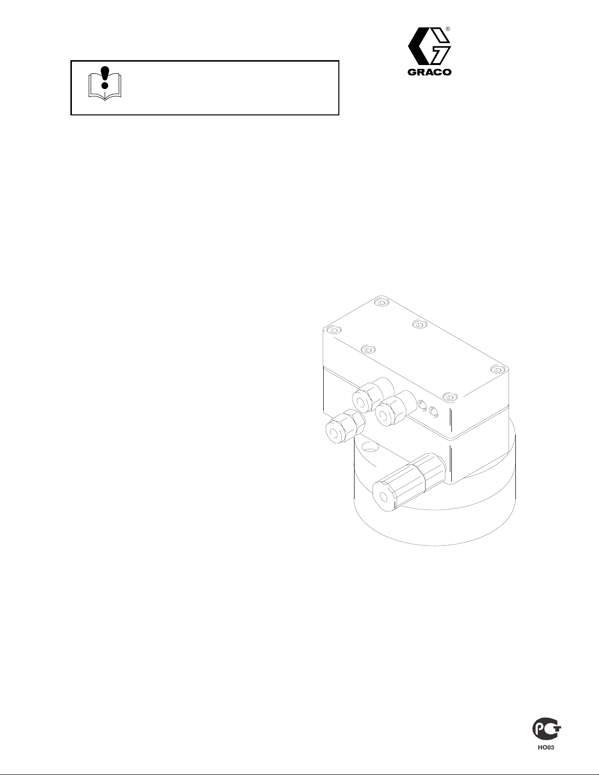
Electronic Volumetric Flow Meter
For use with Plural Component Precision Mixing Systems
This meter is designed to be used in a Class I, Group D hazardous environment
2800 psi (19.6 MPa, 196 bar) Maximum Working Fluid Pressure
50 psi (350 kPa, 3.5 bar) Maximum Working AirPressure
Part No. 235–402, Series A
Flow
Meter with 0.1 cc per tooth fluid volume flow
Rev. C
Model 235–403, Series A
Flow
Meter with 0.4 cc per tooth fluid volume flow
NOTE:
Optic Cables and to order the Fluid Manifold.
U.S.
See the
and Foreign Patents Pending
Accessories
section to order Fiber
-
01847
GRACO INC. P.O. BOX 1441
COPYRIGHT
Graco
Inc. is registered to I.S. EN ISO 9001
MINNEAPOLIS, MN
1993, GRACO INC.
55440–1441
Page 2
Table
of Contents
Symbols
Warnings 2.
Installation 4
Operation 6
Maintenance 7
Troubleshooting 8
Service 9
Parts 11
Dimensions 15
Technical
Warranty 16
Graco
. . . . . . . . . . . . . . . . . . . . . . . . . . . . . . . . . . . . .
. . . . . . . . . . . . . . . . . . . . . . . . . . . . . . . . . . . .
. . . . . . . . . . . . . . . . . . . . . . . . . . . . . . . . . . . . .
. . . . . . . . . . . . . . . . . . . . . . . . . . . . . . . . . . .
. . . . . . . . . . . . . . . . . . . . . . . . . . . . . . . .
. . . . . . . . . . . . . . . . . . . . . . . . . . . . . . . . . . . . . . .
. . . . . . . . . . . . . . . . . . . . . . . . . . . . . . . . . . . . . . . .
. . . . . . . . . . . . . . . . . . . . . . . . . . . . . . . . . . .
Data
Phone Number
. . . . . . . . . . . . . . . . . . . . . . . . . . . . . . .
. . . . . . . . . . . . . . . . . . . . . . . . . . . . . . . . . . . . .
. . . . . . . . . . . . . . . . . . . . . . . . .
15.
16.
WARNING
INJECTION HAZARD
Spray
from hose leaks or ruptured components can inject fluid into your body and cause an extremely
serious injury
cause a serious injury
Fluid injected into the skin might look like just a cut, but it is a serious injury. Get immediate medi
cal attention.
, including the need for amputation. Splashing fluid in the eyes or on the skin can also
.
Warning Symbol
WARNING
This
symbol alerts you to the possibility of serious
injury or death if you do not follow the instructions.
Caution Symbol
CAUTION
This
symbol alerts you to the possibility of damage to
or destruction of equipment if you do not follow the
corresponding instructions.
-
Do not stop or deflect fluid leaks with your hand, body
Follow the
sure; stop operation, or clean, check, or service the equipment; and install or clean the spray tip.
T
ighten all the fluid connections before operating the equipment.
Check the hoses, tubes, and couplings daily
Permanently coupled hoses cannot be repaired; replace the entire hose.
Pressure Relief Procedure
on page 6 whenever you: are instructed to relieve pres
. Replace worn, damaged, or loose parts immediately
, glove, or rag.
FIRE, EXPLOSION, AND ELECTRIC SHOCK HAZARD
This
The meter’
equipment must only be installed by trained and qualified personnel.
s electrical chassis must be properly grounded. See
on page 5.
Do not allow water or other liquids to spill on the electrical chassis.
Do not immerse the chassis in fluids.
The air line to the electrical chassis must be turned OFF and the pressure relieved before servicing
or flushing the meter
.
Check the Electrical Grounding
-
.
308–287
Page 3

WARNING
EQUIPMENT MISUSE HAZARD
INSTRUCTIONS
Equipment
in a serious injury
D
This equipment is for professional use only
D
Read all the instruction manuals, tags, and labels before operating the equipment.
D
Use the equipment only for its intended purpose. If you are uncertain about usage, call your Graco
distributor.
D
Do not alter or modify this equipment. Use only genuine Graco parts and accessories.
D
Check the equipment daily
D
Do not exceed the maximum working pressure of the lowest rated system component. This equip
ment has a
D
Use fluids that are compatible with the equipment wetted parts. See the Technical Data
all the equipment manuals. Read the fluid manufacturer’s warnings.
D
Route the hoses away from traffic areas, sharp edges, moving parts, and hot surfaces. Do not
expose Graco hoses to temperatures above 180
D
Comply with all applicable local, state, and national fire, electrical, and other safety regulations.
misuse can cause the equipment to rupture, malfunction, or start unexpectedly and result
.
.
. Repair or replace worn or damaged parts immediately
2800 psi (19.6 MPa, 196 bar) maximum working pressure.
_F (82_
C) or below –40
_F (–40_C).
.
section of
-
3308–287
Page 4
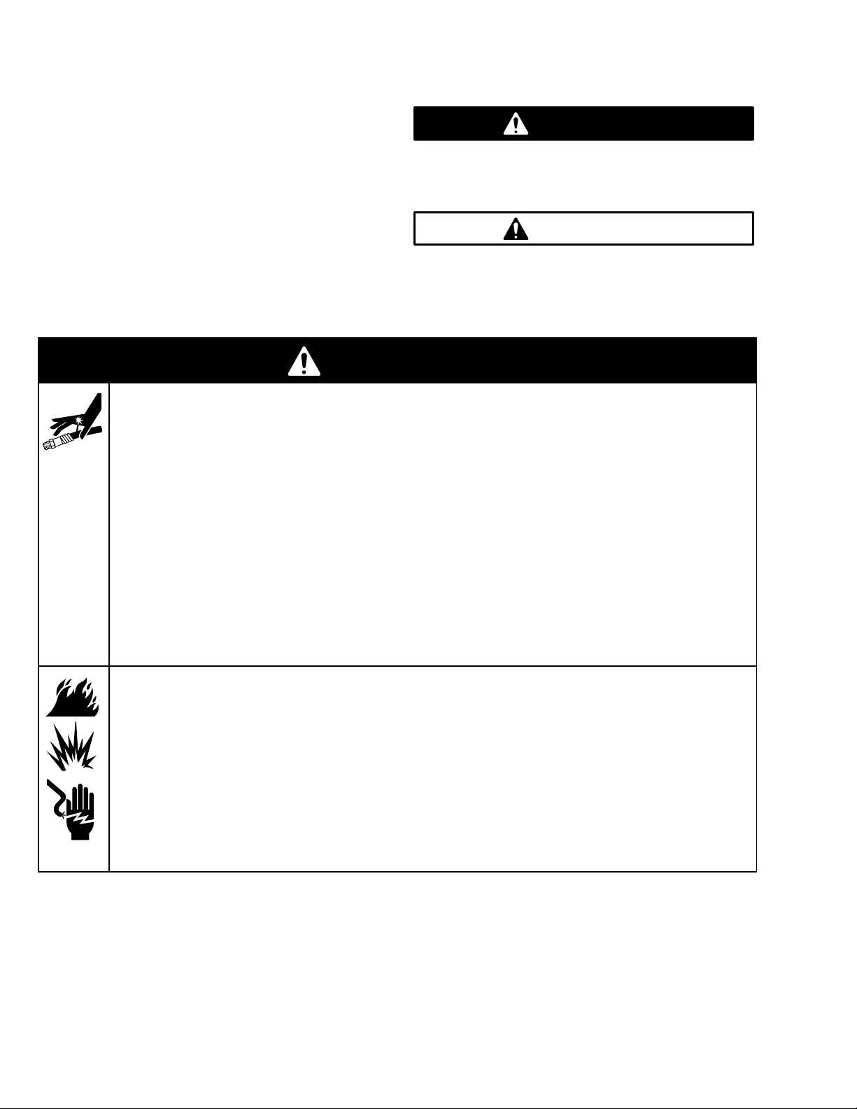
Installation
L
AB
1
A
B
KEY
A Air
Supply Line
B Bleed-T
C
D
E
F Pump
G
H
J
K
L
M Pendant
N
P
R 1
S Controller
ype Air Supply Line
Shut-of
f V
alve
Air Line Filter
Air Line Lubricator
Air Line Regulator
Fiber Optic Cable
Flow Meter
Fluid Supply Line
Fluid Supply
Main Power Switch
Pump Grounding Wire
Fluid Manifold
15V 60 Hz Electrical Supply
(required)
2
CD E
CDE
(required)
M
F
N
R
S
G
J
K
NON-HAZARDOUS
H
HAZARDOUS AREA
P
AREA
The PRO Pulse V
olumetric Flow Meter is designed to
detect the pulses induced on a magnetic sensor each
time a gear tooth passes by the sensor
. A specific
volume of fluid flows through the meter with each gear
tooth rotation. See the front cover for the specific fluid
volume flow of your meter
.
Installing the System
WARNING
To
help reduce the risk of serious injury
splashing in the eyes or on the skin, the bleed-type
air shut-of
f valve (B1) must be installed in the
system to relieve air trapped between this valve
and the pump after the air is shut of
can cause the pump to cycle unexpectedly
the valve close to the pump.
4 308–287
, including
f. T
rapped air
. Locate
The T
ypical Installation shown above is only a guide
for selecting and installing the flow meter
. For assis
01848
tance in designing a particular type and size system for
your application, contact your Graco representative.
Install the air line accessories in the order shown in the
T
ypical Installation, using adapters as necessary
.
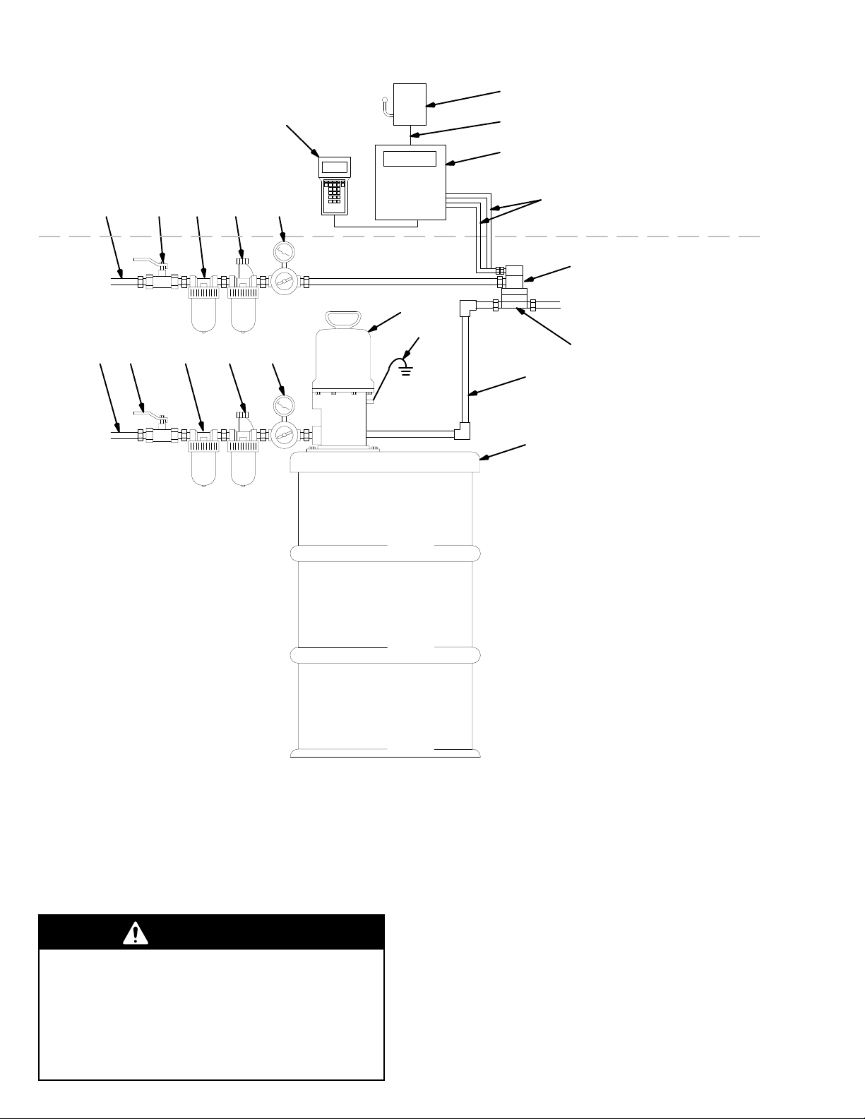
Connect the air line to the Flow Meter by pressing the
front ferrule (D) and back ferrule (C) onto the tubing
(A). See Fig. 1. Press the assembly into the fitting (E)
and tighten the nut (A). Connect the fiber optic cables
by pressing the front ferrule (L) and back ferrule (K)
onto the cable (G).
The maximum fiver optic cable length is 100 ft (30.5
m) with two splices. See
Accessories
on page 14 to
order cables.
Page 5
Installation
KEY
A Tubing,
B
C
D
E
F
G
H
J
K
L
1/4” OD
Nut (nylon)
Ferrule, back (nylon)
Ferrule, front (nylon)
Air Inlet Fitting
Electrical Chassis
Fiber Optic Cables
Gear Housing Assy
Nut (aluminum)
Ferrule, back (aluminum)
Ferrule, front (aluminum)
.
K
J
G
A
Fig. 1
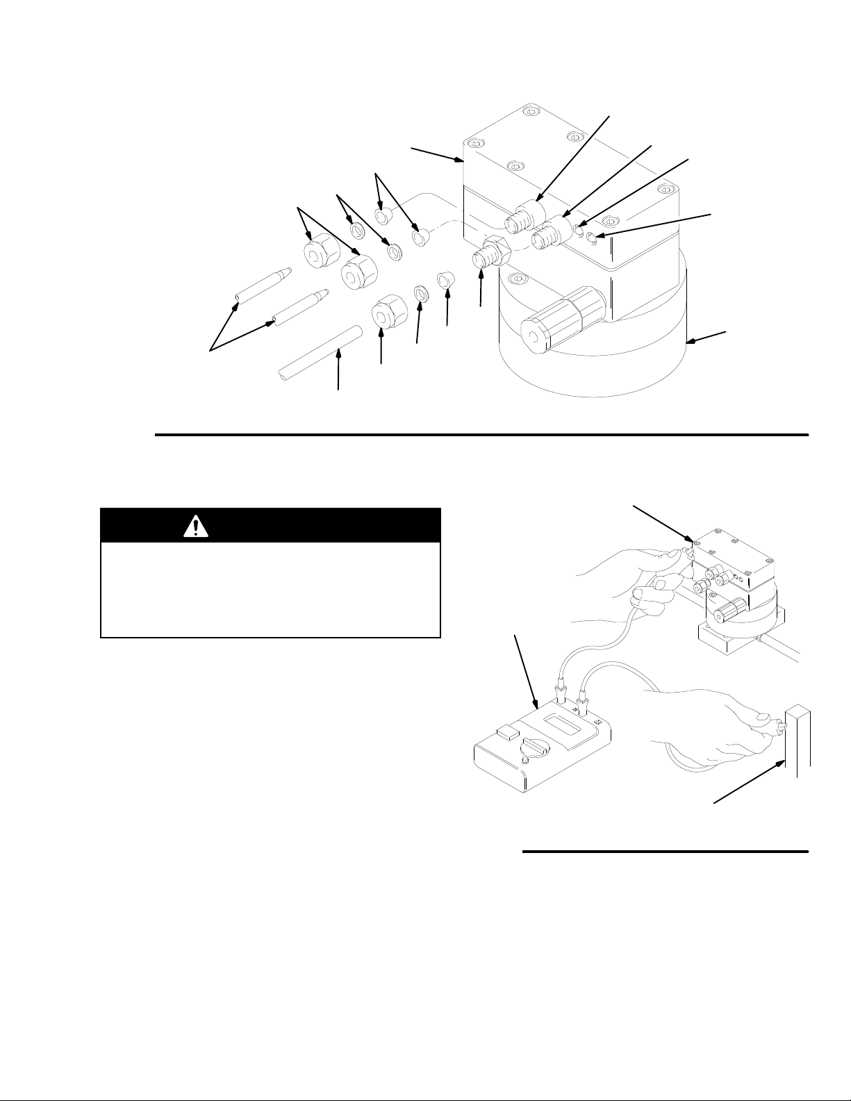
Check the Electrical Grounding
Fiber
Optic
Sender
F
L
1
Fiber
Sender
Optic
2
Power Indicator
Light
(Yellow)
Flow
Indicator
Light
(Green)
E
D
H
C
B
01849
Electrical
Chassis
WARNING
Proper
electrical grounding of your system is
essential when used with flammable or combustible
liquids. For you safety
FIRE, EXPLOSION, AND ELECTRIC SHOCK
HAZARD
on page 2.
Have a qualified electrician check the electrical
grounding continuity between the flow meter electrical
chassis and a true earth ground as shown in Fig. 2. If
the resistance is greater than 25 ohms, check the
mounting or add a ground strap to the chassis.
, read the warning section
Digital
Voltage
Meter
True Earth Ground
01850
Fig. 2
5308–287
Page 6

Operation
Pressure Relief Procedure
WARNING
INJECTION
Fluid under high pressure can be in
jected through the skin and cause
serious injury
injury from injection, splashing fluid, or moving
parts, follow the
whenever you:
are instructed to relieve the pressure,
stop operating,
or check or service any of the system equip
ment.
1. T
urn of
f the air supply to the meter
Allow air to exhaust out of the exhaust air port.
2.
3. T
urn of
f the fluid supply to the meter
Shut of
4.
air system.
5.
Follow the Pressure Relief Procedure for your fluid
system dispensing device.
f all electrical power to the fluid system or
HAZARD
. T
o reduce the risk of an
Pressure Relief Procedure
.
.
System Operating Checklist
Check
the following list daily
the system, to help ensure you of safe, ef
tion.
-
-
Be sure all operators are properly trained and
qualified to safely operate your system.
Be sure all operators are trained how to properly
and completely relieve system pressure according
to the
Pressure Relief Procedure
Be sure the system is thoroughly grounded. See
FIRE, EXPLOSION, AND ELECTRIC SHOCK
HAZARD
Grounding
Be sure the operator and all persons entering the
installation site are properly grounded by wearing
shoes with conductive soles or personal grounding
straps.
Be sure ventilation fans are operating properly
, page 2, and
, page 5.
, before starting to operate
ficient opera
, at left.
Check the Electrical
.
-
Operation
Operate the flow meter between 20–50 psi (140–350
kPa, 1.4–3.5 bar) air inlet pressure. The yellow flow
meter indicator light will come on when the proper air
pressure is supplied. The green flow meter indicator
light will blink on and of
f when the fluid is flowing.
6 308–287
Page 7

CAUTION
Maintenance
Flushing the Meter
Do not immerse the meter in solvent. Solvent could
damage the meter’s electrical components.
1.
Clean the fluid and air line filters daily
2.
Clean the outside of the meter with a soft cloth
dampened in a compatible solvent as needed.
3.
Flush the fluid supply line and meter fluid reservoir
daily with a compatible solvent as instructed at
right.
.
WARNING
To
reduce the risk of serious injury whenever you
are instructed to relieve pressure, always follow the
Pressure Relief Procedure
1.
Relieve the pressure.
2.
Connect the fluid line to the solvent supply unit.
3.
Flush the meter until it is clean.
4.
Relieve the pressure
line from the solvent supply unit.
5.
Reconnect the fluid line to the fluid (paint) supply
urn on the fluid supply
6. T
Operate until the meter and fluid line are free of
7.
solvent.
on page 6.
, then disconnect the fluid
.
.
7308–287
Page 8

Troubleshooting
Y
ellow LED is of
f; no power to
WARNING
Installing and servicing this equipment requires
access to parts that may cause electric shock or
other serious injury if the work is not performed
properly
unless you are trained and qualified.
T
o reduce the risk of serious injury whenever you
are instructed to relieve pressure, always follow the
Pressure Relief Procedure
. Do not install or service this equipment
on page 6.
Before servicing this equipment always make sure to
relieve the pressure
.
Problem
Y
ellow LED is of
flow meter
Green LED is of
f; no power to
f
Cause Solution
Insuf
ficient air supply
T
urbine alternator not working Check for dirt or moisture in turbine.
Faulty turbine alternator
Excess moisture in air lines
T
urbine not connected to PC board
T
op PC board not connected to bot
tom PC board
Alternator shorted to chassis Check that insulating pad (2a) is in
Meter gasket (5) is damaged
Dried paint/fluid in gear track (gears
are not moving)
W
orn gears
Electronic failure
Adjust air regulator
Be sure plug is in place on back of
turbine alternator housing. Remove
and test alternator
Use filter-moisture separator
Connect 3-pin connector to square
pins.
-
T
ighten bolts to compress gasket to
0.040” (1.02 mm)
place. Replace pad if necessary
Replace gasket.
Flush fluid section of meter as
instructed in
7, or disassemble and clean the
gear housing assembly
Replace faulty gears.
Replace meter
.
.
Maintenance
.
.
.
.
on page
8 308–287
Page 9

WARNING
Service
2.
Disconnect the 3-pin connector (J) from the square
pins (H).
Installing and servicing this equipment requires
access to parts that may cause electric shock or
other serious injury if the work is not performed
properly
. Do not install or service this equipment
unless you are trained and qualified.
T
o reduce the risk of serious injury whenever you
are instructed to relieve pressure, always follow the
Pressure Relief Procedure
NOTE:
shooting
1.
Check all possible remedies in the
section before disassembling the meter
Relieve the pressure
on page 6.
Trouble-
and flush the meter as
described on page 7.
2.
Disconnect the fiber optic cable(s) (G) from the
electronic module (B). See Fig. 3.
3.
Disconnect the air hose fitting and remove the air
hose from the motor
. Disconnect both fluid hose
fittings and remove the fluid hose from the meter
4.
Remove the four screws (A) to separate the gear
housing (F) from the manifold.
3.
Carefully pull the alternator (4) away from the top
housing.
4.
Using an ohmmeter
alternator
. Measure the resistance between the
, test the coil in the turbine
two outer terminals of the 3-pin connector (J). The
resistance should be 3–5 ohms. If the reading
varies from this value, replace the alternator (4).
5.
Lubricate the alternator o-ring (4a) seal with petro
leum jelly
.
-
.
6.
Insert the alternator (4) into the top chassis (3).
7.
Connect the 3-pin connector (J) to the 3 square
pins (H) in the top chassis (3).
8.
Check to see that the gasket (5) is not damaged. If
damaged, replace the gasket.
9.
Snap the top and bottom chassis together
.
.
10.
Install and tighten the chassis screws (9) to 40
in-lbs (4.52 N
m).
CAUTION
Never remove the electronic module (B) from the top
gear housing (E). The electronic module is calibrated
to the gear housing assembly and will not function
properly if removed.
Torque
KEY
A Screw
Electronic Module
B
C O-Ring
D Manifold
op Gear Housing
ET
F
Gear Housing Assy
Fiber Optic Cable
G
G
.
E
to 7.5
ft-lb (10 N
m)
A
B
F
C*
D
KEY
H Pins
J 3-pin
2
3T
4 Alternator
4a
5 Gasket
9 Chassis Screws
Connector
Bottom Chassis
op Chassis
Alternator O-Ring
4a
9
orque to
T
40 in-lb
(4.52 N
m)
3
H
4
J
5
2
Fig. 3
Replacing the Turbine Alternator
1. Remove
chassis (2). See Fig. 4.
the top chassis (3) from the bottom
01851
Fig. 4
0180A
9308–287
Page 10

Service
Replacing Worn Bearings
A
repair kit is available to service the bearings. An
asterisk after the description or reference letter indi
cates a part included with the repair kit. See page 1
to order the proper kit for your meter model.
CAUTION
This is a close-tolerance device. It will be damaged if
forced apart during disassembly
1.
Loosen the four screws (N). See Fig. 5. Leave
about two threads connected.
.
Install the o-ring (M*), washers (K*), and gear
3.
assemblies (L*). Be sure to install the gears on
-
1
their proper pegs. See Fig. 5.
4.
Press the gear housings together and secure them
with the four screws (N). T
ft-lbs (10 N
Install the meter back onto the adapter plate.
5.
When installing the screws (A), replace the meter
two o-rings (C*) with the o-rings from the kit.
T
orque screws to 7.5 ft-lbs (10 Nm). See Fig. 3.
m).
orque the screws to 7.5
’s
2.
The two halves of the gear housing are pegged
together and will be dif
are part of the top gear housing (E).
Hold the housing and tap the screws one at a time
in a consistent sequence and eventually the two
halves will come apart.
3.
Before removing the gears (L), note which peg the
gear is being removed from. The gears must be
installed on the same peg they were removed
from.
ficult to separate. The pegs
CAUTION
Always reinstall the gears on the peg they were
removed from to ensure proper calibration with the
electronic module.
4.
Remove the gears (L) and washers (K).
5.
Support a gear on its sides and position the bear
ing tool (T*) as shown in Fig. 6. Make sure the
gear has suf
out the bearings and spacers.
ficient clearance in the center to press
NOTE:
o-rings that match the o-rings you are replacing and
discard the others.
Kit 223–276 has two sets of o-rings. Use the
CAUTION
Never immerse a meter in solvent for cleaning. Doing
so will damage the electronics.
KEY
ET
op Gear Housing
K Washer
Gear Assembly
L
M O-Ring
N Screw
-
K*
LE
K*
6.
Press the bearing tool with an arbor press or tap it
with a soft hammer until the bearings and spacers
are removed. Repeat with the other gear
To install th
1.
Place a gear on a flat surface. Position the bear
ings (P*), spacers (R* and S*) and the bearing tool
(T*) as shown in Fig. 7.
2.
Press the bearing tool with the arbor press or tap it
with a soft hammer until bearings and spacers are
installed into the gear
10 308–287
e k
it part
s a
nd assemble the gea
. Repeat with the other gear
.
r h
ousing:
M*
Replace
disassembled
-
1b
.
Fig. 5
N
Torque
7.5 ft-lb
(10 N
m)
whenever
to
01852A
Page 11

Service
Removing Bearings Installing Bearings
KEY
L Gear
T*
V*
W Support
Assembly
Bearing T
Bearings and Spacers
ool
L
Fig.
6
*T
KEY
L Gear
*T
P* Bearing
Inner Spacer
R*
S*
Outer Spacer
T*
Bearing T
Flat Surface
U
ool
R*
P*
V
W
0968
*S
P*
L
U
0969
Fig. 7
Parts
Bearing Repair Kit 223–276
For
Meter Model 235–402,
with 0.1 cc per tooth fluid volume flow
Bearing Repair Kit 223–277
For
Meter Model 235–403,
with 0.4 cc per tooth fluid volume flow
Bearing Repair Kits include the following parts:
Ref.
Letter Description Qty.
C O-RINGS,
K WASHER 4
M O-RING 1
P BEARINGS 4
R INNER SPACER 2
S OUTER SPACER 2
T BEARING TOOL 1
(not shown, See Fig. 3)
2 or 4
T
Gears
not
included
with Kit
K
P
R
S
P
K
M
0967
11308–287
Page 12

Parts
Part No. 235–402, Series A
0.1
cc per tooth fluid volume flow
3
30
29
28
5
16
4a
4
Part No. 235–403
with
0.4 cc per tooth fluid volume flow
8
17
15
14
Model
1a
1b
only
Model
1
9
2a
2
6
7
10
11
12
13
235–402
235–403 only
12 308–287
Page 13

Parts
Part No. 235–402, Series A
0.1
cc per tooth fluid volume flow
Part No. 235–403, Series A
0.4
cc per tooth fluid volume flow
Ref
No.
1
1a 111–073
1b 111–070
2 224–277
2a 186–924
3 224–276
4 224–603 ALTERNAT
4a 110–073
5 186–852 GASKET
6 111–157
7 186–853
8 110–420 SCREW
9 111–308 SCREW
Part No.
Description Qty.
GEAR HOUSING ASSY
information below; Includes
replaceable items 1a & 1b
. O-RING, fluid housing; PTFE
. O-RING, fluid ports; PTFE
CHASSIS ASSY
Includes item 2a
. P
AD, insulating
CHASSIS ASSY
OR; Includes item 4a
. O-RING, alternator; V
, adhesive backing
FITTING, air inlet; 1/4” tube
FLAME ARREST
, cap; 10–24 x 1.5”
, top mounting;
M4 x 0.7 x 30 mm long
; Ordering
1
2
, bottom;
, top
iton 1
OR 1
Ref
No.
10 186–922
11 107–107 W
12 186–921 BODY 1
13 101–435 BALL 1
14 108–046 SPRING 1
15 186–923 RETAINER 1
16* 187–125
17* 187–124
28 111–284 NUT
1
29 111–285
30 111–286
*
1
Graco.
1
1
Viton
1
Company.
1
To Order Gear Housing Assembly (item 1)
1
To
6
the complete flow meter assembly back to your local
Graco distributor
2
brated when a new gear housing is installed.
Part No.
Additional warning labels available at no charge from
is a registered trademark of the Du Pont
replace the Gear Housing Assembly
Description Qty.
FITTING, valve
ASHER, flow
LABEL, warning
LABEL, warning
, tube fitting; 1/4” OD
FERRULE, back; 1/4” OD
FERRULE, front; 1/4” OD
, you must send
. The flow meter needs to be recali
1
1
1
1
2
2
2
-
13308–287
Page 14

Accessories
Fiber Optic Cables
Fiber
Optic Cable Assembly
For connection between the controller and flow meter
P
ART NO.
224–690 6 ft (1.8 m)
224–691 15 ft (5 m)
224–692 25 ft (8 m)
224–693
224–694 50 ft (15 m)
224–695 75 ft (23 m)
224–696
Fiber Optic Cable Extender
For connection between the flow meter and bulkhead
connector or between two bulkhead connectors.
P
ART NO.
224–670 6 ft (1.8 m)
224–671 15 ft (5 m)
224–672 25 ft (8 m)
224–673
224–674 50 ft (15 m)
224–675 75 ft (23 m)
224–676
LENGTH
36 ft (1
100 ft (30.5 m)
LENGTH
36 ft (1
100 ft (30.5 m)
1 m)
1 m)
Bulkhead Connector 224–261
For
connection between two fiber optic cables.
Fluid Manifold
.
Contact
proper manifold.
your local Graco representative to order
0186 0187
Part
No. 223–869
Part No. 624–708
Fluid Filter 223–160
5000 psi (35.
Stainless steel bowl and polyethylene support.
NOTE:
premature flow meter wear
Order Part No. 167–026 when you order the filter
0 M
Pa
, 350 b
ar) Maximu
This filter has a 60 mesh screen. T
, use a 100 mesh screen.
m W
orkin
g P
ressure
o prevent
.
100 Mesh Filter Screen 167–026
For
use with Fluid Filter 223–160.
Bleed-type Master Air Valve 107–142
Grounding Clamp and Wire 222–011
12
ga, 25 ft (7.6 m) wire
300
psi (2.1 MPa, 21 bar) Maximum Working Pressure
Relieves air trapped in the air line between the pump
air inlet and this valve when closed. 1/2” npt
14 308–287
Page 15

DIM. C
DIM. A
Dimensions
DIM. B
Part
No.
235–402
235–403
Dim. A Dim. B Dim. C
4.25 in
(108 mm)
4.25 in
(108 mm)
4.10 in.
(104 mm)
4.25 in.
(108 mm)
4.44 in.
(113 mm)
4.50 in.
(114 mm)
01847
Technical
Category Data
Maximum Working Fluid Pressure
Maximum W
Fluid Pressure Operating Range
Air Pressure Operating Range
Air Inlet
Maximum Fiber Optic Cable Length
W
etted Parts
orking Air Pressure
Manual
This
manual was revised to include the changes from PCN C.
2800 psi (19.6 MPa, 196 bar)
50 psi (350 kPa, 3.5 bar)
0–2800 psi (0–19.6 MPa, 0–196 bar)
20–50 psi (140–350 kPa, 1.4–3.5 bar)
1/4 inch OD tube
100 ft (30.5 m) with two splices
Stainless Steel, PTFE
Change Summary
Data
15308–287
Page 16

The
Graco
warrants all equipment listed in this manual which is manufactured by Graco and bearing its name to be free from defects in
material
any
replace
operated
This
faulty installation, misapplication, abrasion, corrosion, inadequate or improper maintenance, negligence, accident, tampering, or
substitution
Graco
installation,
This
verification
equipment
in
transportation.
Graco’s
remedy (including, but not limited to, incidental or consequential damages for lost
other incidental or consequential loss) shall be available. Any action for breach of warranty must be brought within two
date
GRACO
A PARTICULAR PURPOSE IN CONNECTION WITH ACCESSORIES, EQUIPMENT
NOT MANUFACTURED BY GRACO. These items sold, but not manufactured by Graco (such as electric motors, gas engines,
switches,
in
In
hereunder,
breach
and workmanship on the date of sale by an authorized Graco distributor to the original purchaser for use. With the exception
special extended or limited warranty published by Graco, Graco will,
any part of the equipment determined by Graco to be defective. This warranty applies only when the
and maintained in accordance with Graco’
warranty does not cover
of non-Graco component parts. Nor shall Graco be liable for malfunction, damage or wear caused by the incompatibility of
equipment with structures, accessories, equipment or materials not supplied by Graco, or the
operation or maintenance or structures, accessories, equipment or materials not supplied by Graco.
warranty is conditioned upon the prepaid return of the equipment claimed to be defective to an authorized Graco distributor for
of the claimed defect. If the claimed defect is verified, Graco will repair or replace free of charge any defective parts. The
will be returned to the original purchaser transportation prepaid. If inspection of the equipment does not disclose any defect
material or
of sale.
making any claim for breach of these warranties.
no event will Graco be liable for indirect, incidental, special or consequential damages resulting from Graco supplying equipment
workmanship, repairs will be made at a reasonable charge, which charges may include the costs of parts, labor
sole obligation and buyer’s sole remedy for any breach of warranty shall be as set forth above.
MAKES NO W
hose, etc.), are subject to the warranty
or the furnishing, performance, or use of any products or other goods sold hereto, whether due to a breach of contract,
of warranty
, the negligence of Graco, or otherwise.
, and Graco shall not be liable
ARRANTY
, AND DISCLAIMS ALL
Graco W
s written recommendations.
for general wear and tear
IMPLIED W
, if any
, of their manufacturer
ARRANTIES OF MERCHANT
arranty
of
for a period of twelve months from the date of sale, repair or
equipment is installed,
, or any malfunction, damage or wear caused by
improper design, manufacture,
, and
The buyer agrees that no other
profits,
lost sales, injury to person or property
(2)
ABILITY AND FITNESS FOR
, MA
TERIALS OR COMPONENTS SOLD BUT
. Graco will provide purchaser with reasonable assistance
, or any
years of the
FOR
GRACO CANADA CUST
The
parties acknowledge that they have required that the present document, as well as all documents, notices and legal proceedings
entered into, given or instituted pursuant hereto or relating directly or indirectly hereto, be drawn up in English. Les parties
reconnaissent
judiciaires
TO
PLACE AN ORDER
avoir convenu que la rédaction du présente document sera en Anglais,
exécutés, donnés ou intentés à la suite de ou en rapport, directement ou indirectement, avec les procédures concernées.
OMERS
Graco
Phone Number
, contact your Graco distributor
1–800–367–4023 T
ainsi que tous documents, avis et procédures
, or call this number to identify the distributor closest to you:
oll Free.
All
written and visual data contained in this document reflects the latest product information available at the time of publication.
Graco reserves the right to make changes at any time without notice.
Foreign Offices:
Sales Offices:
Belgium, Canada, England, Korea, France, Germany
GRACO INC. P.O. BOX 1441
PRINTED
IN U.S.A. 308–287 February 1993, Revised July 1997
Minneapolis, Detroit, Los Angeles
MINNEAPOLIS, MN
, Hong Kong, Japan
55440–1441
16 308–287
 Loading...