

Page 1
INSTRUCTIONS-PARTS
PTFEPTFEPTFE
LIST
308–230
This
manual contains important
warnings and information.
READ AND KEEP FOR REFERENCE.
INSTRUCTIONS
Husky
307
First
quality counts.
Air Spray/HVLP Systems
STAINLESS STEEL FLUID FITTINGS,
ACETAL PUMP WITH
0.7 MPa, 7 bar (100 psi) Maximum Fluid Working Pressure
0.7 MPa, 7 bar (100 psi) Maximum Air Input Pressure
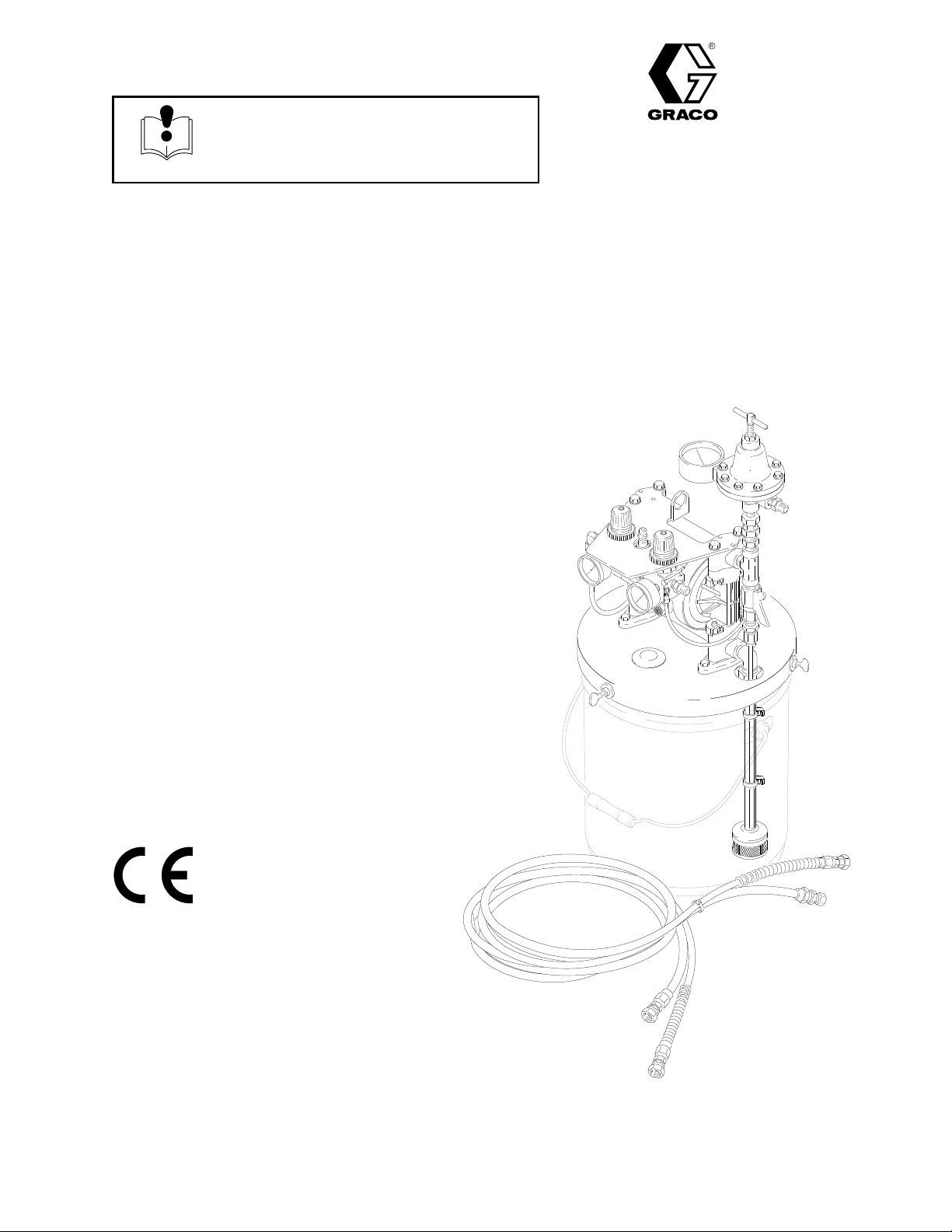
Model 236–870, Series A
Pail
Mount Unit with Fluid Regulator
Model 224–833, Series B
Pail
Mount Unit with Fluid Regulator and Hose Kit
DIAPHRAGM
choice when
Rev. J
Supersedes Rev H
and PCN J
Model 236–412, Series A
Pail
Mount Unit with Surge T
Model 236–869, Series A
Wall
Mount Unit with Surge T
Model 236–628, Series A
Wall
Mount Unit with Surge T
Model 236–414, Series A
Wall
Mount Unit with Surge T
Model 236–868, Series A
Wall
Mount Unit with Surge T
ank and Hose Kit
ank and Suction Kit
ank and Hose Kit
ank, Suction Kit, and Hose Kit
ank
Model
224–833 Shown
(Pail is not included)
GRACO INC. P.O. BOX 1441
COPYRIGHT
Graco
Inc. is registered to I.S. EN ISO 9001
MINNEAPOLIS, MN
1992, GRACO INC.
55440–1441
Page 2
Table
of Contents
Symbols
Warnings 2.
Installation 4
Operation 10
Parts 12
Dimensions 18
Technical
Warranty Back
Graco T
. . . . . . . . . . . . . . . . . . . . . . . . . . . . . . . . . . . . .
. . . . . . . . . . . . . . . . . . . . . . . . . . . . . . . . . . . .
. . . . . . . . . . . . . . . . . . . . . . . . . . . . . . . . . . . .
. . . . . . . . . . . . . . . . . . . . . . . . . . . . . . . . . . . . . . . .
. . . . . . . . . . . . . . . . . . . . . . . . . . . . . . . . . . .
Data
.
. . . . . . . . . . . . . . . . . . . . . . .
.
. . . . . . . . . . . . . . . . . . . . . . . . . . . .
oll-Free Phone Numbers
.
. . . . . . .
Back Cover
Cover
Back Cover
WARNING
WARNING
EQUIPMENT MISUSE HAZARD
INSTRUCTIONS
Equipment
This equipment is for professional use only
misuse can cause the equipment to rupture or malfunction and result in serious injury
Warning Symbol
WARNING
his
symbol alerts you to the possibility of serious
injury or death if you do not follow the instructions.
Caution Symbol
CAUTION
This
symbol alerts you to the possibility of damage to
or destruction of equipment if you do not follow the
instructions.
.
.
Read all instruction manuals, tags, and labels before operating the equipment.
Use the equipment only for its intended purpose. If you are unsure about usage, call your Graco
distributor.
Do not alter or modify this equipment. Use only genuine Graco parts and accessories.
Check equipment daily
Do not exceed the maximum working pressure of the lowest rated component in your system.
This equipment has a
MPa, 7 bar) maximum incoming air pressure.
Use fluids and solvents which are compatible with the equipment wetted parts. Refer to the
nical Data
ings.
Do not use hoses to pull equipment.
Route hoses away from traffic areas, sharp edges, moving parts, and hot surfaces. Do not ex
pose Graco hoses to temperatures above 82C (180F) or below –40C (–40
W
ear hearing protection when operating this equipment.
Do not lift pressurized equipment.
section of all equipment manuals. Read the fluid and solvent manufacturer’s warn
. Repair or replace worn or damaged parts immediately
100 psi (0.7 MPa, 7 bar) maximum working pressure at 100 psi (0.7
.
F).
Tech-
-
-
Comply with all applicable local, state, and national fire, electrical, and safety regulations.
Page 3
TOXIC FLUID HAZARD
WARNING
WARNING
Hazardous
skin, inhaled, or swallowed.
Know the specific hazards of the fluid you are using.
Store hazardous fluid in an approved container
state and national guidelines.
Always wear protective eyewear
and solvent manufacturer
Pipe and dispose of the exhaust air safely
If the diaphragm fails, the fluid is exhausted along with the air
the separate pump manual 308–553.
fluid or toxic fumes can cause serious injury or death if splashed in the eyes or on the
. Dispose of hazardous fluid according to all local,
, gloves, clothing and respirator as recommended by the fluid
.
, away from people, animals, and food handling areas.
. See
Air Exhaust V
entilation
FIRE AND EXPLOSION HAZARD
Improper
result in a fire or explosion and serious injury
grounding, poor ventilation, open flames or sparks can cause a hazardous condition and
.
Ground the equipment. Refer to
If there is any static sparking or you feel an electric shock while using this equipment,
pumping immediately. Do not use the equipment until you identify and correct the problem.
Provide fresh air ventilation to avoid the buildup of flammable fumes from solvents or the fluid
being pumped.
Grounding
on page 9.
in
stop
Pipe and dispose of the exhaust air safely
fails, the fluid is exhausted along with the air
manual 308–553.
Keep the work area free of debris, including solvent, rags, and gasoline.
Electrically disconnect all equipment in the work area.
Extinguish all open flames or pilot lights in the work area.
Do not smoke in the work area.
Do not turn on or of
Do not operate a gasoline engine in the work area.
f any light switch in the work area while operating or if fumes are present.
, away from all sources of ignition. If the diaphragm
. See
Air Exhaust V
entilation
in the separate pump
Page 4
Installation
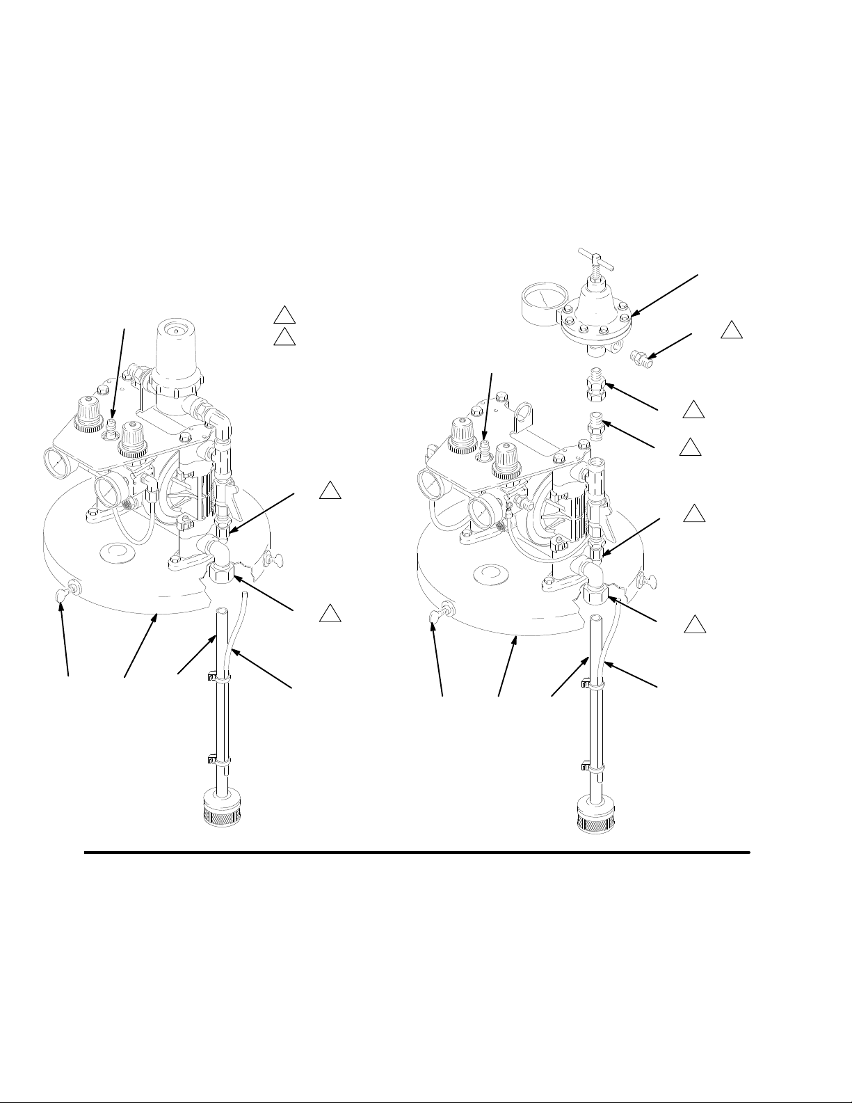
Assembling Pail Mount Units
1. Insert
2.
the suction tube (27) into the elbow (15) to
its full depth. Tighten the nut securely
. See Fig. 1.
Insert the recirculation tube (28) into the connector
(16) to its full depth. T
ighten the nut securely
3.
On Models 236–870 and 224–833,
assemble the
Fluid Regulator Kit (items 17, 21, 24 and 32) as
shown in Fig. 1.
4.
Attach the pail cover (2) to a pail of fluid, using the
.
thumbscrews (3). T
ighten securely
.
Model 236–412 Models 236–870
and 224–833
1
Tighten
22
2
nut securely with wrench.
Apply thread sealant to male threads.
22
16
1
15
1
32
21
16
15
17
24
2
2
2
1
1
Fig. 1
4 308-230
23
27
28
28
2723
04964
04965
Page 5

Installation
Assembling the Wall Mount Unit
Install
the wall bracket (2) 5 ft (1.52 m) above the floor
Use the mounting hole layout shown on page 18. Be
sure the wall is strong enough to support the weight of
the pump and hoses, any accessories, the fluid, and
stress caused by pump operation.
The following steps apply to Model 236–414 only:
Apply thread sealant and screw the connector (28) into
the pump’
s fluid inlet. See Fig. 2.
.
22
2
29
1
Slide the bung plug (31) onto the suction tube (33).
Push the 0.625 in. (16 mm) OD suction tube into the
elbow (30) to its full depth, then tighten the nut secure
ly with a wrench.
Push the 0.5 in. (13 mm) OD flexible tube (29) into the
elbow (30) to its full depth, then tighten the nut secure
ly with a wrench. Push the other end of the flexible
tube into the connector (28) to its full depth, then tight
en the nut securely with a wrench.
Screw the bung plug (31) into the drum bung opening.
Adjust the suction tube (33) so the end of the tube is
about 1/2 in. (13 mm) of
f the bottom of the drum, and
secure using the thumbscrew (32).
30
28
3
33
2
31
-
Insert tube (29) into connector (28)
-
1
to full depth and tighten nut
securely with wrench.
tube
Insert
2
full
securely with wrench.
3
Apply
(33) into elbow (30) to
depth and tighten nut
thread sealant to male threads.
Fig. 2
32
02773
308-230 5
Page 6
Installation
PTFEPTFEPTFE
General Information
1. The T
2.
3.
4.
ypical Installations shown on pages 7 and
8 are only a guide for selecting and installing sys
tem components. Contact your Graco distributor or
Graco T
assistance in planning a system to suit your needs.
Always use Genuine Graco Parts and Accesso
ries, available from your Graco distributor
the Product Data Sheet for the pump, Form No.
305–528. If you supply your own accessories, be
sure they are adequately sized and pressure rated
for your system.
Use a compatible, liquid thread sealant or
tape on all male threads. T
firmly to avoid air or fluid leaks.
tighten plastic threads.
Reference numbers and letters in parentheses re
fer to the callouts in the Figures and the parts lists
on pages 12–17.
echnical Assistance (see back page) for
ighten all connections
Do not over-
WARNING
T
OXIC FLUID HAZARD
Hazardous fluid or toxic fumes can
cause serious injury or death if splashed
in the eyes or on the skin, inhaled, or
swallowed.
1. Read T
OXIC FLUID HAZARD
on page 3.
-
-
. Refer to
Accessories
WARNING
A bleed-type master air valve (B) is required in
your system to relieve air trapped between this
valve and the pump. Trapped air can cause the
pump to cycle unexpectedly
serious injury
the skin, injury from moving parts, or contamination
from hazardous fluids.
A fluid drain valve (J) is required in your system to
relieve pressure in the hose if it is plugged. (The
fluid recirculation valve supplied with Models
236–870, 224–833, and 236–412 will serve this
purpose.) The drain valve reduces the risk of seri
ous injury
skin, or contamination from hazardous fluids when
-
relieving pressure. Install the valve close to the
pump’
s fluid outlet.
1.
Install the air line accessories as shown in Figs. 3
and 4. Mount these accessories on the wall or on a
bracket. Be sure the air line supplying the acces
sories is grounded.
a.
, including splashing in the eyes or on
, including splashing in the eyes or on the
Locate one bleed-type master air valve (B)
close to the pump and use it to relieve trapped
air
. See the
er master air valve (E) upstream from all air
line accessories and use it to isolate them dur
ing cleaning and repair
WARNING
, which could result in
above. Locate the oth
.
-
-
-
-
2.
Use fluids and solvents which are compatible
with the equipment wetted parts. Refer to the
T
echnical Data
als. Read the fluid and solvent manufacturer
warnings.
section of all equipment manu
b.
The air line filter (F) removes harmful dirt and
moisture from the compressed air supply
-
’s
Install an electrically conductive, flexible air hose
2.
(C) between the accessories and the pump. Use a
minimum 1/4” (6.3 mm) ID air hose. Screw an air
line quick disconnect coupler (D) onto the end of
the air hose (C). Do not connect the coupler (D) to
the air inlet fitting (22, see Figs. 1 and 2) yet.
.
Hose Connections
1. Read
2.
3.
the entire spray gun manual before connect
ing the hoses and operating the sprayer
Connect a fluid hose (N) between the pump fluid
outlet fitting and the fluid inlet of the spray gun (R).
See Figs. 3 and 4.
Connect an electrically conductive air hose (P) be
tween the outlet fitting of the gun air regulator (G)
and the air inlet of the spray gun (R).
.
-
-
6 308-230
Page 7

E
R
Y
Installation
BC
F
M
D
G
NP
L
H
A
J
K
S
Air
Spray T
ypical Installation –
Pail Mount Models with Surge Tank
KEY
A Husky
B Bleed-T
C
D
E
F
G
H
J
K
L
M
N
P
R
S
Y
NOTE:
included with the sprayer
model. Refer to the parts lists on pages
12–17 for parts included in your sprayer
307 Pump
ype Master Air V
(required for pump)
Air Supply Line
Air Line Quick Disconnect
Master Air V
Air Line Filter
Gun Air Regulator
Pump Air Regulator
Fluid Drain V
Fluid Recirculation Line
Fluid Suction Line
Surge T
Gun Fluid Supply Hose
Gun Air Supply Hose
Air Spray Gun
Pail Cover
Ground Wire (included)
See page 9 for grounding instructions.
Some components shown are
alve (for accessories)
alve (required)
ank and Filter
alve
, depending on the
.
HVLP T
ypical Installation –
Pail Mount Models with Fluid Regulator
KEY
A
Husky 307 Pump
B Bleed-T
C
D
E
F
G
H
J
K
L
M
N
P
R
S
Y
NOTE:
included with the sprayer
model. Refer to the parts lists on pages
12–17 for parts included in your sprayer
ype Master Air V
(required for pump)
Air Supply Line
Air Line Quick Disconnect
Master Air V
Air Line Filter
Gun Air Regulator
Pump Air Regulator
Fluid Drain V
Fluid Recirculation Line
Fluid Suction Line
Fluid Regulator and Gauge
Gun Fluid Supply Hose
Gun Air Supply Hose
Optimiser HVLP Spray Gun
Pail Cover
Ground Wire (included)
See page 9 for grounding instructions.
Some components shown are
alve (for accessories)
alve (required)
alve
, depending on the
.
04967
E
B
F
C
M
D
G
H
A
Y
J
R
K
L
S
P
N
Fig. 3
04966
308-230 7
Page 8

Installation
Air
Spray T
Wall Mount Models with Surge Tank
F
E
R
Y
J
N
B
D
G
C
M
H
A
KEY
A Husky
B Bleed-T
(required for pump)
C
Air Supply Line
D
Air Line Quick Disconnect
E
Master Air V
F
Air Line Filter
G
Gun Air Regulator
H
Pump Air Regulator
J
Fluid Drain V
L
Fluid Suction Line
M
Surge T
N
Gun Fluid Supply Hose
P
Gun Air Supply Hose
R
Air Spray Gun
SW
all Bracket
Y
Ground Wire (included)
See page 9 for grounding instructions.
S
ypical Installation –
307 Pump
ype Master Air V
alve (for accessories)
alve (required)
ank and Filter
alve
P
NOTE:
Some components shown are
included with the sprayer
model. Refer to the parts lists on pages
12–17 for parts included in your sprayer
Fig.
4
, depending on the
L
.
04973
Page 9

Installation
Grounding
WARNING
FIRE
AND EXPLOSION HAZARD
This pump must be grounded. Before
operating the pump, ground the system
as explained below. Also read the sec
tion
FIRE OR EXPLOSION HAZARD
page 3.
T
o reduce the risk of static sparking, ground the pump
and all other equipment used or located in the pumping
area. Check your local electrical code for detailed
grounding instructions for your area and type of equip
ment.
Ground all of this equipment.
1.
Pump
: One end of the ground wire (Y) is con
nected to the pump grounding strip (Z). Connect
the clamp end of the ground wire to a true earth
ground.
on
-
2.
Air and fluid hoses
tive hoses.
3.
Spray gun:
are grounded with a ground wire (34) connected
between the gun air regulator and the pump
grounding strap (Z).
4.
Object being sprayed:
5.
Fluid supply container:
6.
Air compressor
mendations.
7.
-
Solvent pails used when flushing
cal code. Use only metal pails, which are conduc
tive. Do not place the pail on a non-conductive sur
face, such as paper or cardboard, which interrupts
the grounding continuity
The spray gun and the gun air hose
: Use only electrically conduc
Follow your local code.
Follow your local code.
: Follow the manufacturer’s recom
: Follow your lo
.
-
-
-
-
-
Fig. 5
Y
34
Z
04963
Page 10

Pressure Relief Procedure
PTFEPTFEPTFE
Operation
1.
Be sure the pump is properly grounded. Read
FIRE OR EXPLOSION HAZARD
on page 3.
WARNING
PRESSURIZED
The system pressure must be manually relieved to
prevent the system from starting or spraying acci
dentally. T
dental spray from the gun, splashing fluid, or mov
ing parts, follow the
whenever you:
are instructed to relieve the pressure,
stop spraying,
check or service any of the system equipment,
or install or clean the spray tips.
1.
Shut of
2. T
3.
Open the fluid drain valve to relieve all fluid pres
sure, having a container ready to catch the drain
age.
f the air to the pump.
rigger the spray gun.
Flush the Pump Before First Use
The
pump was tested in water
could contaminate the fluid you are pumping, flush the
pump thoroughly with a compatible solvent. Follow the
procedure in
EQUIPMENT HAZARD
o reduce the risk of an injury from acci
Pressure Relief Procedure
. If the test solution
Starting and Adjusting the Pump.
-
-
-
-
-
2.
Check all fittings to be sure they are tight. Be sure
to use a compatible liquid thread sealant or
tape on all male threads. T
outlet fittings snugly
into the pump.
3.
On pail mount units,
pail of fluid and attach the pail cover using the
thumbscrews. T
On wall mount units,
bung plug in the fluid supply drum as explained on
page 5.
4.
Make sure the air regulators (G and H) and bleed
valves (B and E) are closed. Open the fluid drain
valve (J).
5.
Connect the air line coupler (D) to the air inlet fit
ting.
6.
With the gun air regulator (G) closed, open the
bleed-type master air valves (B, E) and the pump
air regulator (H).
7.
Allow the pump to cycle slowly until all air is
pushed out of the recirculation line and the pump
is primed.
. Do not overtighten the fittings
ighten securely
ighten the fluid inlet and
place the suction tube in a
.
install the suction tube and
-
Starting and Adjusting the Pump
WARNING
TOXIC
Hazardous fluid or toxic fumes can
cause serious injury or death if splashed
in the eyes or on the skin, inhaled, or
swallowed. Do not lift a pump under pressure. If
dropped, the fluid section may rupture. Always fol
low the
lifting the pump.
Pressure Relief Procedure
FLUID HAZARD
above before
8.
Point the spray gun (R) into a grounded metal pail,
holding a metal part of the gun firmly to the side of
the pail.
9. T
rigger the air spray gun. Open the gun air regula
tor (G) and close the fluid drain valve (J). Allow the
pump to cycle slowly until all air is pushed out of
the fluid hose and gun.
-
If you are flushing,
thoroughly clean the pump and hoses. Close the
air regulator
solvent and place it in the fluid to be pumped.
run the pump long enough to
. Remove the suction tube from the
-
10 308-230
Page 11

Operation
Pump Shutdown
WARNING
To
reduce the risk of serious injury whenever you
are instructed to relieve pressure, always follow the
Pressure Relief Procedure
At the end of the work shift,
on page 10.
relieve the pressure.
Flushing and Storage
WARNING
To
reduce the risk of serious injury whenever you
are instructed to relieve pressure, always follow the
Pressure Relief Procedure
Flush the pump when necessary to prevent the fluid
you are pumping from drying or freezing in the pump
and damaging it. Use a compatible solvent.
Before storing the pump, always flush the pump and
relieve the pressure.
on page 10.
Recirculation Line
The
recirculation tube (K, supplied with Models
236–870, 224–833, and 236–412) drains unused fluid
back into the fluid container, ensuring an even flow at
the gun. Recirculation also provides gentle fluid agita
tion. T
o recirculate fluid, open the drain valve (J) while
you are spraying. T
o stop recirculation, close the valve.
Surge Tank (Models 236–628, 236–869,
236–412, 236–868, and 236–414)
WARNING
To
reduce the risk of serious injury whenever you
are instructed to relieve pressure, always follow the
Pressure Relief Procedure
The surge tank filter screen may require periodic
cleaning. First,
surge tank cover from its base and remove the filter
screen. Clean the screen with a compatible solvent
and reinstall it in the surge tank.
An optional V
tank, for use in applications where the standard EPDM
gasket is unsuitable.
relieve the pressure.
iton
gasket is supplied for the surge
on page 10.
Unscrew the
-
308-230 11
Page 12

Model 236–412, Series A
PTFEPTFEPTFE
Includes items 1–42
Parts
Ref Part
No. No. Description Qty
1 D31–331 PUMP, Husky 307; SST/ r;
See 308–553 for parts
2 235–505 COVER, pail; stainless steel 1
3 111–276 THUMBSCREW
1” (25.4 mm) long; sst
4 104–119 SCREW
0.875” (22 mm) long; sst
5 104–123 LOCKWASHER; 1/4” size; sst 4
6 102–025 NUT
7 101–754
8 103–473
9 111–813
10 108–190 GAUGE, air pressure;
11 110–209 NUT
12 111–804 REGULATOR, air;
13 111–805 BLOCK, diverter
13a 108–284 . O-RING; buna-N 3
14 111–807 ELBOW
15 111–808 ELBOW
16 111–811 CONNECT
17 111–793 T
17a 111–884 . SCREEN, 20 mesh; sst 1
17b 112–035 . GASKET
111–885 . GASKET
18 237–534 VAL
19 111–928
PLUG, pipe; 3/8 npt
TIE, recirculation tube
PLUG, button
0–100 psi (0–0.7 MPa, 0–7 bar)
0–125 psi (0–0.85 MPa, 0–8.5 bar)
pressure range
Includes item 13a
1/4 npt(m) x ferrule nut for
0.25” (6.3 mm) OD tube
3/8 npt(m) x ferrule nut for
0.625” (16 mm) OD tube
3/8 npt(m) x ferrule nut for
0.25” (6.3 mm) OD tube
Includes items 17a and 17b
TEE; 3/8 npt(f) run x
3/8 npt(m) branch; sst
, cap, hex hd; 1/4–20 unc–2a;
, hex; 1/4–20; sst
, regulator
, tube fitting, 90_; acetal;
, tube fitting, 90_; acetal;
ANK, surge; 1/2 npt(f); nylon
(alternative to EPDM; shipped loose)
VE, ball; 3/8 npt (m x f); sst
; 5/16–18 unc;
OR, tube fitting; acetal;
; EPDM (standard part)
; V
itonr;
Ref Part
No. No. Description Qty
20 112–026 ELBOW
1
21 112–027
22 169–971
23 188–077
3
24 188–380
25 188–093 BRACKET
4
26 188–107
4
1
27 188–108
3
1
28 188–115
2
2
29 181–163 HOUSING, filter
30 181–164 FIL
2
31Y 189–220
34 223–324 GROUND WIRE; 12” (300 mm);
1
35 108–290 SCREW
38 236–410 HOSE KIT
2
39 235–339 .
1
40 210–867 .
1
41 102–478 .
1
42 222–011
1
Use only GENUINE GRACO PARTS AND ACCESSORIES.
1
1
Y
Replacement Danger and W
1
are available at no cost.
NIPPLE; 1/2 npt x 3/8 npt; sst
FITTING, air line; 3/8 npt(m)
NIPPLE; 1/4–18 npt x 1/4–18.6 sf; cst
NIPPLE; 1/2 npt x 3/8–18.6 sf; sst
TUBE, inlet, air; nylon;
0.25” (6.3 mm) OD; 0.170” (4.3 mm) ID;
7.5” (191 mm) long
TUBE, suction; nylon;
0.625” (16 mm) OD x 0.5” (13 mm) ID;
12.13” (308 mm) long
TUBE, recirculation, fluid; nylon;
0.25” (6.3 mm) OD;
0.170” (4.3 mm) ID; 19” (483 mm) long
LABEL, warning
from gun air regulator to pump
8–32 x 1/4” (6.3 mm)
Includes items 39–41
GROUND WIRE; 12 gauge (1.5 mm2),
25 ft (7.6 m); with clamp
, street; 3/8 npt (m x f); sst
, air regulator
, inlet; nylon
TER, inlet; nylon
, machine;
HOSE, fluid; nylon; sst fittings;
3/8 npsm (fbe); 1/4” (6.3 mm) ID;
26 ft (7.9 m) long
HOSE, air; buna-N; cst fittings
1/4 npsm (fbe); 5/16” (7.9 mm) ID;
25 ft (7.6 m) long
TIE, hose
arning labels, tags and cards
1
1
1
1
1
1
1
1
1
1
1
1
1
1
1
1
1
13
1
12 308-230
Page 13

Model 236–412, Series A
Includes items 1–42
1
2
3
4
5
6
7
to 35–55 in–lb (4.0–6.2 N.m). Do not over-torque.
Torque
Insert tube into connector (16) to full depth and
tighten nut securely with wrench.
Insert tube into elbow (14) to full depth and
tighten nut securely with wrench.
Insert tube into elbow (15) to full depth and
tighten nut securely with wrench.
T
orque to contact plus 1/2 turn.
Apply
thread sealant to male threads.
Pail
is not included.
11
5
12
23
6
34
35
22
13a
Parts
25
6
14
6
26
3
Part
of item 17
17a
24
6
31
17b
Part
17
21
of item 1
6
20
1
6
34 (Ref)
1
19
6
A
15
6
42
10
6
13
6
Ref.
No. 38, Hose Kit,
Includes Items 39–41.
18
6
3
7
27
2
4
14
6
26
3
7
A
4
5
9
6
16
28
6
2
8
41
29
30
40
39
04974A
308-230 13
Page 14

Model 236–870, Series A
PTFEPTFEPTFE
Includes items 1–35 and 42
Model 224–833, Series B
Includes items 1–42
Parts
Ref Part
No. No. Description Qty
1 D31–331 PUMP, Husky 307; SST/ r;
See 308–553 for parts
2 235–505 COVER, pail; stainless steel 1
3 111–276 THUMBSCREW
1” (25.4 mm) long; sst
4 104–119 SCREW
0.875” (22 mm) long; sst
5 104–123 LOCKWASHER; 1/4” size; sst 4
6 102–025 NUT
7 101–754
8 103–473
9 111–813
10 108–190 GAUGE, air pressure;
11 110–209 NUT
12 111–804 REGULATOR, air;
13 111–805 BLOCK, diverter
13a 108–284 . O-RING; buna-N 3
14 111–807 ELBOW
15 111–808 ELBOW
16 111–811 CONNECT
17{ 236–449 REGULAT
18 237–534 VAL
19 111–928
21{ 188–089
22 169–971
PLUG, pipe; 3/8 npt
TIE, recirculation tube
PLUG, button
0–100 psi (0–0.7 MPa, 0–7 bar)
0–125 psi (0–0.85 MPa, 0–8.5 bar)
pressure range
Includes item 13a
1/4 npt(m) x ferrule nut for
0.25” (6.3 mm) OD tube
3/8 npt(m) x ferrule nut for
0.625” (16 mm) OD tube
3/8 npt(m) x ferrule nut for
0.25” (6.3 mm) OD tube
3–30 psi (21–210 kPa, 0.2–2.1 bar)
pressure range
See manual 308–325
TEE; 3/8 npt(f) run x
3/8 npt(m) branch; sst
NIPPLE; 3/8 npt x 3/8–18.6 sf; sst
FITTING, air line; 3/8 npt(m)
, cap, hex hd; 1/4–20 unc–2a;
, hex; 1/4–20; sst
, regulator
, tube fitting, 90_; acetal;
, tube fitting, 90_; acetal;
VE, ball; 3/8 npt (m x f); sst
; 5/16–18 unc;
OR, tube fitting; acetal;
OR, fluid; acetal;
Ref Part
No. No. Description Qty
23 188–077
1
24{ 189–436
25 188–093 BRACKET
26 188–107
3
4
27 188–108
4
1
28 188–115
3
1
29 181–163 HOUSING, filter
2
30 181–164 FIL
2
31Y 189–220
32{ 112–497
2
34 223–324 GROUND WIRE; 12” (300 mm);
1
35 108–290 SCREW
38 236–410 HOSE KIT
2
39 235–339 .
1
40 210–867 .
1
41 102–478 .
42 222–011
Use only GENUINE GRACO PARTS AND ACCESSORIES.
1
1
{
These parts are included in Fluid Regulator Kit 235–344.
1
1
Y
Replacement Danger and W
1
are available at no cost.
NIPPLE; 1/4-18 npt x 1/4-–8.6 sf; cst
NIPPLE; 1/4-18 npt x 3/8–18.6 sf; sst
, air regulator
TUBE, inlet, air; nylon;
0.25” (6.3 mm) OD; 0.170” (4.3 mm) ID;
7.5” (191 mm) long
TUBE, suction; nylon;
0.625” (16 mm) OD x 0.5” (13 mm) ID;
12.13” (308 mm) long
TUBE, recirculation, fluid; nylon;
0.25” (6.3 mm) OD;
0.170” (4.3 mm) ID; 19” (483 mm) long
, inlet; nylon
TER, inlet; nylon
LABEL, warning
SWIVEL, union; 1/4-18 npt x
3/8–18.6 npsm
from gun air regulator to pump
, machine;
8–32 x 1/4” (6.3 mm)
Includes items 39–41
HOSE, fluid; nylon; sst fittings;
3/8 npsm (fbe); 1/4” (6.3 mm) ID;
26 ft (7.9 m) long
HOSE, air; buna-N; cst fittings;
1/4 npsm (fbe); 5/16” (7.9 mm) ID;
25 ft (7.6 m) long
TIE, hose
GROUND WIRE; 12 gauge (1.5 mm2),
25 ft (7.6 m); with clamp
arning labels, tags and cards
1
1
1
1
1
1
1
1
1
1
1
1
1
1
1
13
1
14 308-230
Page 15

Model 236–870, Series A
Includes items 1–35 and 42
Model 224–833, Series B
Includes items 1–42
1
orque to 35–55 in–lb (4.0–6.2 N.m). Do not over-torque.
T
Insert tube into connector (16) to full depth and
2
tighten nut securely with wrench.
Insert tube into elbow (14) to full depth and
3
tighten nut securely with wrench.
Insert tube into elbow (15) to full depth and
4
tighten nut securely with wrench.
5
T
orque to contact plus 1/2 turn.
6
Apply
thread sealant to male threads.
7
Pail is not included.
5
11
14
6
12
A
Parts
These
parts are included in
Fluid Regulator Kit 235–344.
of item 1
Part
31
25
1
22
6
6
14
3
26
13a
A
34 (Ref)
15
6
1
17
24
6
32
6
21
6
19
6
42
26
3
10
6
Ref. No. 38, Hose Kit,
Includes Items 39–41.
6
18
13
6
7
6
27
2
4
4
9
23
3534
7
3
6
5
6
16
28
2
8
41
29
30
40
39
04975A
308-230 15
Page 16

Model 236–628, Series A
PTFEPTFEPTFE
Includes items 1–26 and 34–42
Model 236–868, Series A
Includes items 1–26, 34–37, and 42
Model 236–869, Series A
Includes items 1–37 and 42
Model 236–414, Series A
Includes items 1–42
Parts
Ref Part
No. No. Description Qty
1 D31–331 PUMP, Husky 307; SST/ r;
See 308–553 for parts
2 224–835 WALL BRACKET KIT
Includes items 3–6
3 188–285 . BRACKET
4 104–119 . SCREW
0.875” (22 mm) long; sst
5 104–123 . LOCKWASHER; 1/4” size; sst 4
6 102–025 . NUT
7 101–754
10 108–190 GAUGE, air pressure;
11 110–209 NUT
12 111–804 REGULATOR, air;
13 111–805 BLOCK, diverter
13a 108–284 . O-RING; buna-N 3
14 111–807 ELBOW
17 111–793 T
17a 111–884 . SCREEN, 20 mesh; sst 1
17b 112–035 . GASKET
111–885 . GASKET
20 112–026 ELBOW
21 112–027
22 169–971
23 188–077
24 188–091
188–380
25 188–093 BRACKET
PLUG, pipe; 3/8 npt
0–100 psi (0–0.7 MPa, 0–7 bar)
0–125 psi (0–0.85 MPa, 0–8.5 bar)
pressure range
Includes item 13a
1/4 npt(m) x ferrule nut for
0.25” (6.3 mm) OD tube
ANK, surge; 1/2 npt(f); nylon
Includes items 17a and 17b
(alternative to EPDM; shipped loose)
NIPPLE, reducing;
1/2 npt x 3/8 npt; sst
FITTING, air line; 3/8 npt(m)
NIPPLE; 1/4–18 npt x 1/4–18.6 sf; cst
NIPPLE; 1/2 npt x 3/8–18.6 sf; cst
(Models 236–628 and 236–414 only)
NIPPLE; 1/2 npt x 3/8–18.6 sf; sst
(Model 236–869 only)
, wall
, cap, hex hd; 1/4–20 unc–2a;
, hex; 1/4–20; sst
, regulator
, tube fitting, 90_; acetal;
; EPDM (standard part)
; V
itonr;
, street; 3/8 npt (m x f); sst
, air regulator
Ref Part
No. No. Description Qty
26 188–107
1
1
27 235–500 SUCTION KIT
1
28 111–864 . CONNECT
4
29 188–173 .
4
1
30 111–863 . ELBOW
2
2
31 188–181 .
32 111–276 . THUMBSCREW
2
33 188–171 .
1
34 223–324 GROUND WIRE; 12” (300 mm);
2
35 108–290 SCREW
1
37Y 189–220
38 236–410 HOSE KIT
1
39 235–339 .
1
2
40 210–867 .
1
1
1
41 102–478 .
42 222–011
1
Use only GENUINE GRACO PARTS AND ACCESSORIES.
1
1
Replacement Danger and W
Y
are available at no cost.
TUBE, inlet, air; nylon;
0.25” (6.3 mm) OD; 0.170” (4.3 mm) ID;
7.5” (191 mm) long
Includes items 28–33
OR; acetal; 3/8 npt(m) x
0.5 in. (13 mm) tube
TUBE, flexible; nylon;
0.5 in. (13 mm) OD;
72 in. (1.83 m) long
, connector
0.625 in. (16 mm) OD tube x
0.5 in. (13 mm) OD tube
PLUG, bung; acetal
1” (25.4 mm) long; sst
TUBE, suction; acetal;
0.625 in. (16 mm) OD;
38 in. (965 mm) long
from gun air regulator to pump
, machine;
8–32 x 1/4” (6.3 mm)
LABEL, warning
Includes items 39–41
HOSE, fluid; nylon; sst fittings;
3/8 npsm (fbe); 1/4” (6.3 mm) ID;
26 ft (7.9 m) long
HOSE, air; buna-N; cst fittings
1/4 npsm (fbe); 5/16” (7.9 mm) ID;
25 ft (7.6 m) long
TIE, hose
GROUND WIRE; 12 gauge (1.5 mm2),
25 ft (7.6 m); with clamp
arning labels, tags and cards
, reducing; acetal;
; 5/16–18 unc;
1
1
1
1
1
1
1
1
1
1
1
1
1
1
13
1
16 308-230
Page 17

Model 236–628, Series A
Includes items 1–26 and 34–42
Model 236–868, Series A
Includes items 1–26, 34–37, and 42
Parts
Model 236–869, Series A
Includes items 1–37 and 42
Model 236–414, Series A
Includes items 1–42
1
2
3
4
5
6
6
to 35–55 in–lb (4.0–6.2 N.m). Do not over-torque.
Torque
Insert tube into connector (28) to full depth and
tighten nut securely with wrench.
Insert tube into elbow (14) to full depth and
tighten nut securely with wrench.
Insert tube into elbow (30) to full depth and
tighten nut securely with wrench.
T
orque to contact plus 1/2 turn.
Apply
thread sealant to male threads.
11
5
12
34
23
35
10
6
13
7
6
22
13a
6
3
14
26
Part of item 17
17a
24
6
37
17b
Part
17
of item 1
1
25
21
6
20
6
34 (Ref)
1
20
6
14
6
26
3
6
42
A
30
4
5
28
6
29
3
2
33
4
6
A
32
31
41
Ref.
No. 38, Hose Kit,
Includes Items 39–41.
33
(Ref
)
40
39
04976A
308-230 17
Page 18

Model
)
236–412
Dimensions
Models 236–870 and 224–833
13.1 in.
(332.7 mm)
Pail is not included.
Maximum pail outer diameter is 12.125 in. (308 mm).
15.1 in.
(383.5 mm)
13.1 in.
(332.7 mm)
Pail
is not included.
Maximum pail outer diameter is 12.125 in. (308 mm).
17.5
in.
(444.5 mm)
Wall
5
in.
(127
mm)
Four
0.438 in. (1
(T
o Mount Bracket T
18 308-230
Mounting
Hole Layout
9.0 in.
(228.6 mm)
(WALL
1 mm) Dia. Holes
o W
VIEW
OF
MOUNTING
BRACKET)
6.74 in.
(171.2 mm)
all)
8 in.
(203 mm
0654
Page 19

Technical
PTFEPTFEPTFE
Data
Wetted Parts
Pump
.
. . . . . . . . . . . . . . . . . . . . . . . . . . . . . . . .
Pail
Cover (236–870, 224–833,
236–412)
Fluid Hoses
Hose
Surge
236–869)
Fluid
Fittings
Tubing
Suction
.
. . . . . . . . . . . . . . . . . . . . . . . . . .
.
. . . . . . . . . . . . . . . . . . . . . . . . . . . . . . . . .
Couplings
T
ank (236–412, 236–414, 236–628, 236–868,
Regulator (236–870, 224–833)
.
. . . . . . . . . . . . . . . . . . . . . . .
. . . . . . . . . . . . . . . . . . . . . . . . . . . . . . . . . . . . . . .
T
ube (236–414 and 236–869)
.
. . . . . . . . . . . . . . . . . . . . . .
nylon, EPDM or V
.
. . . . .
acetal,
Manual
This
manual was revised to include the changes from PCN J.
See 308–553
stainless steel
nylon
stainless steel
iton
, stainless steel
See 308–325
.
. . . . .
stainless steel
nylon
.
. . . . . . . . . .
acetal
Change Summary
Maximum
Air
Pump Air Inlet Size
Pump
* Sound
Operating Temperature Range:
* Tested to CAGI-PNEUROP–1969
Fluid W
Pressure Operating Range
Fluid Inlet and Outlet Size. 3/8 npt(f)
Data
Pump sound level at 100 psi (0.7 MPa, 7 bar), full flow
.
. . . . . . . . . . . . . . . . . . . . . . . . . . . . . . . . . . . . . . . . . .
Pump
sound level at 70 psi (480 kPa, 4.8 bar),
1 gpm (3.8 lpm)
is a registered trademark of the Du Pont Co.
orking Pressure
.
. . . . . . . . . . . . . . . . . . . . . . . . . .
.
. . . . . . . . . . . . . . . . . . . . . . . . . . . .
100 psi (0.7 MPa, 7 bar)
.
.
. . . . . . . . . . . . . .
(104–700
.
. . . . . . . . . . . . . .
40
to 150F (4.4 to 65.5
kPa, 1–7 bar)
15–100 psi
1/4 npt(f)
85 dB(A)
7
8 dB(A)
C)
308-230 19
Page 20

The
Graco
warrants all equipment listed in this manual which is manufactured by Graco and bearing its name to be free from defects in
material
any
replace
operated
This
faulty installation, misapplication, abrasion, corrosion, inadequate or improper maintenance, negligence, accident, tampering, or
substitution
Graco
installation,
This
verification
equipment
in
transportation.
Graco’s
remedy (including, but not limited to, incidental or consequential damages for lost
other incidental or consequential loss) shall be available. Any action for breach of warranty must be brought within two
date
GRACO
A PARTICULAR PURPOSE IN CONNECTION WITH ACCESSORIES, EQUIPMENT
NOT MANUFACTURED BY GRACO. These items sold, but not manufactured by Graco (such as electric motors, gas engines,
switches,
in
In
hereunder,
breach
and workmanship on the date of sale by an authorized Graco distributor to the original purchaser for use. With the exception
special extended or limited warranty published by Graco, Graco will,
any part of the equipment determined by Graco to be defective. This warranty applies only when the
and maintained in accordance with Graco’
warranty does not cover
of non-Graco component parts. Nor shall Graco be liable for malfunction, damage or wear caused by the incompatibility of
equipment with structures, accessories, equipment or materials not supplied by Graco, or the
operation or maintenance or structures, accessories, equipment or materials not supplied by Graco.
warranty is conditioned upon the prepaid return of the equipment claimed to be defective to an authorized Graco distributor for
of the claimed defect. If the claimed defect is verified, Graco will repair or replace free of charge any defective parts. The
will be returned to the original purchaser transportation prepaid. If inspection of the equipment does not disclose any defect
material or
of sale.
making any claim for breach of these warranties.
no event will Graco be liable for indirect, incidental, special or consequential damages resulting from Graco supplying equipment
workmanship, repairs will be made at a reasonable charge, which charges may include the costs of parts, labor
sole obligation and buyer’s sole remedy for any breach of warranty shall be as set forth above.
MAKES NO W
hose, etc.), are subject to the warranty
or the furnishing, performance, or use of any products or other goods sold hereto, whether due to a breach of contract,
of warranty
Graco Warranty and Disclaimers
for a period of twelve months from the date of sale, repair or
equipment is installed,
s written recommendations.
, and Graco shall not be liable
ARRANTY
, the negligence of Graco, or otherwise.
, AND DISCLAIMS ALL
, if any
for general wear and tear
IMPLIED W
, of their manufacturer
ARRANTIES OF MERCHANT
, or any malfunction, damage or wear caused by
improper design, manufacture,
The buyer agrees that no other
profits,
lost sales, injury to person or property
ABILITY AND FITNESS FOR
, MA
TERIALS OR COMPONENTS SOLD BUT
. Graco will provide purchaser with reasonable assistance
(2)
years of the
, and
, or any
of
FOR
GRACO CANADA CUST
The
parties acknowledge that they have required that the present document, as well as all documents, notices and legal proceedings
entered into, given or instituted pursuant hereto or relating directly or indirectly hereto, be drawn up in English. Les parties
reconnaissent
judiciaires
TO
PLACE AN ORDER
avoir convenu que la rédaction du présente document sera en Anglais,
exécutés, donnés ou intentés à la suite de ou en rapport, directement ou indirectement, avec les procédures concernées.
OMERS
Graco
Phone Number
, contact your Graco distributor
1–800–367–4023 T
ainsi que tous documents, avis et procédures
, or call this number to identify the distributor closest to you:
oll Free.
All
written and visual data contained in this document reflects the latest product information available at the time of publication.
Graco reserves the right to make changes at any time without notice.
Foreign Offices:
Sales Offices:
Belgium, Canada, England, Korea, France, Germany
GRACO INC. P.O. BOX 1441
PRINTED
IN U.S.A. 308–230 September 1992, Revised June 1997
Minneapolis, Detroit, Los Angeles
MINNEAPOLIS, MN
, Hong Kong, Japan
55440–1441
 Loading...