

Page 1
Instructions–Parts List
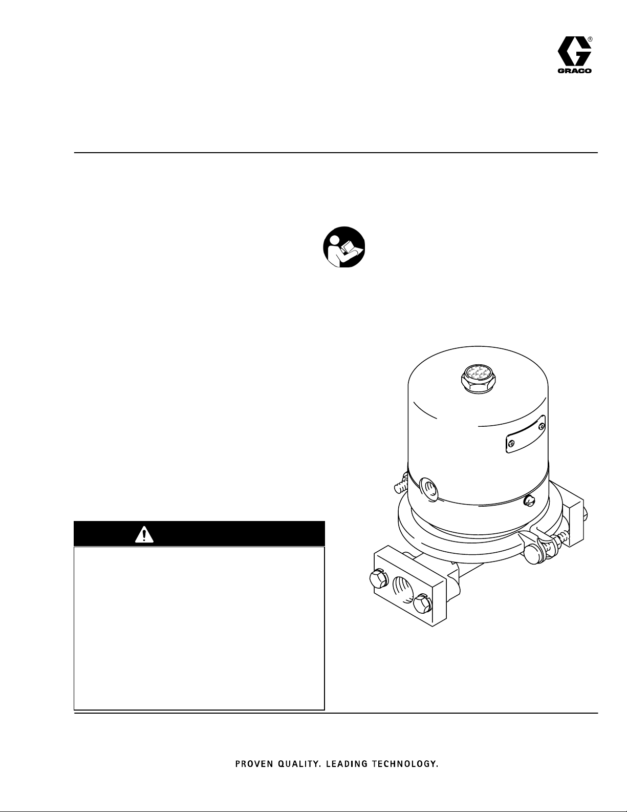
Dynamic Surge Suppressor
For use with double-diaphragm pumps and low-pressure reciprocating pumps.
For professional use only.
100 psi (0.7 MPa, 7 bar) Maximum Fluid Working Pressure
100 psi (0.7 MPa, 7 bar) Maximum Air Inlet Pressure
308178H
EN
Model 224892, Series A
aluminum, with PTFE diaphragm
Model 224893, Series A
aluminum, with buna–N diaphragm
Model 224894, Series C
stainless steel, with PTFE diaphragm
Model 224895, Series C
stainless steel, with buna–N diaphragm
Table of Contents
Warnings 2. . . . . . . . . . . . . . . . . . . . . . . . . . . . . . . . . . .
Installation 4. . . . . . . . . . . . . . . . . . . . . . . . . . . . . . . . . .
Operation and Maintenance 7. . . . . . . . . . . . . . . . . . .
Troubleshooting 8. . . . . . . . . . . . . . . . . . . . . . . . . . . . .
Service 9. . . . . . . . . . . . . . . . . . . . . . . . . . . . . . . . . . . .
Parts Drawing 12. . . . . . . . . . . . . . . . . . . . . . . . . . . . . .
Parts Lists 13. . . . . . . . . . . . . . . . . . . . . . . . . . . . . . . . .
Repair Kits 14. . . . . . . . . . . . . . . . . . . . . . . . . . . . . . . .
Dimensional Drawing 15. . . . . . . . . . . . . . . . . . . . . . .
Technical Data 16. . . . . . . . . . . . . . . . . . . . . . . . . . . . .
Warranty 18. . . . . . . . . . . . . . . . . . . . . . . . . . . . . . . . . .
Graco Phone Number 18. . . . . . . . . . . . . . . . . . . . . . .
Important Safety Instructions
Read all warnings and instructions in this manual.
Save these instructions.
WARNING
Hazard of Using Fluids Containing Halogenated Hydrocarbons
Never use 1.1.1–trichloroethane, methylene
chloride, other halogenated hydrocarbon solvents
or fluids containing such solvents in aluminum
models 224892 or 224893. Such use could result
in a chemical reaction, with the possibility of
explosion, which could cause death, serious bodily
injury, and/or substantial property damage.
Consult your fluid suppliers to ensure that the fluids
being used are compatible with aluminum and zinc
parts.
0903
Page 2
Symbols
Warning Symbol
WARNING
This symbol alerts you to the possibility of serious
injury or death if you do not follow the instructions.
WARNING
WARNING
EQUIPMENT MISUSE HAZARD
Equipment misuse can cause the equipment to rupture or malfunction and result in serious injury.
INSTRUCTIONS
D This equipment is for professional use only.
D Read all instruction manuals, tags, and labels before operating the equipment.
D Use the equipment only for its intended purpose. If you are not sure, call your Graco distributor.
D Do not alter or modify this equipment. Use only genuine Graco parts and accessories.
D Check equipment daily. Repair or replace worn or damaged parts immediately.
Caution Symbol
CAUTION
This symbol alerts you to the possibility of damage to
or destruction of equipment if you do not follow the
instructions.
D Do not exceed the maximum working pressure of the lowest rated component in your system.
See Technical Data on page 16.
D Use fluids and solvents that are compatible with the equipment wetted parts. Refer to the
Technical Data section of all equipment manuals. Read the fluid and solvent manufacturer’s
warnings.
D Route hoses away from traffic areas, sharp edges, moving parts, and hot surfaces. Do not
expose Graco hoses to temperatures above 82_C (180_F) or below –40_C (–40_F).
D Wear hearing protection when operating this equipment.
D Do not lift pressurized equipment.
D Comply with all applicable local, state, and national fire, electrical, and safety regulations.
2 308178
Page 3
WARNING
WARNING
TOXIC FLUID HAZARD
Hazardous fluid or toxic fumes can cause serious injury or death if splashed in the eyes or on the
skin, inhaled, or swallowed.
D Know the specific hazards of the fluid you are using.
D Store hazardous fluid in an approved container. Dispose of hazardous fluid according to all local,
state and national guidelines.
D Always wear protective eyewear, gloves, clothing and respirator as recommended by the fluid
and solvent manufacturer.
D Graco does not manufacture or supply the reactive chemical components that may be used in
this equipment and is not responsible for injury or property loss, damage, expense or claims
(direct or consequential) that arise from the use of such chemical components.
FIRE AND EXPLOSION HAZARD
Improper grounding, poor ventilation, open flames or sparks can cause a hazardous condition and
result in a fire or explosion and serious injury.
D Ground the equipment. See Grounding on page 4.
D If there is any static sparking or you feel an electric shock while using this equipment, stop
pumping immediately. Do not use the equipment until you identify and correct the problem.
D Provide fresh air ventilation to avoid the buildup of flammable fumes from solvents or the fluid
being pumped.
D Keep the work area free of debris, including solvent, rags, and gasoline.
D Electrically disconnect all equipment in the work area.
D Extinguish all open flames or pilot lights in the work area.
D Do not smoke in the work area.
D Do not turn on or off any light switch in the work area while operating or if fumes are present.
D Do not operate a gasoline engine in the work area.
D Never use 1.1.1–trichloroethane, methylene chloride, other halogenated hydrocarbon solvents or
fluids containing such solvents in pressurized aluminum equipment. Such use could result in a
chemical reaction, with the possibility of explosion.
MOVING PARTS HAZARD
Moving parts, such as the air motor piston in the pump, can pinch or amputate your fingers.
D Keep clear of all moving parts when starting or operating the pump.
D Before servicing this surge tank, follow the Pressure Relief Procedure on page 4 to prevent
the equipment from starting accidentally.
United States Government safety standards have been adopted under the Occupational Safety and Health Act.
You should consult these standards––particularly the General Standards, Part 1910.
308178
3
Page 4
Installation
System Pressure
The maximum fluid working pressure of this surge
suppressor is 100 psi (0.7 MPa, 7 bar) at 100 psi
(0.7 MPa, 7 bar) incoming air pressure. Never exceed
100 psi (0.7 MPa, 7 bar) fluid or air pressure to the
surge suppressor. Do not exceed the maximum
working pressure of any component or accessory used
in the system.
Pressure Relief Procedure
WARNING
PRESSURIZED EQUIPMENT HAZARD
To reduce the risk of serious bodily injury, including
splashing fluid or solvent in the eyes or on the skin,
always follow this procedure before you check,
adjust, clean, or repair any part of the system.
1. Close the air regulator by turning counterclockwise
as far as possible.
2. Disconnect the air supply line to the surge
suppressor.
and other flammable substances, whether you are
pumping indoors or outdoors, and can cause a fire or
explosion and serious bodily injury and property
damage.
If you experience any static sparking or even a slight
shock while using this equipment, stop pumping
immediately. Do not use the system again until the
problem has been identified and corrected.
To reduce the risk of static sparking, ground the pump,
surge suppressor, and all other equipment used or
located in the pumping area. Check your local
electrical code for detailed grounding instructions for
your area and type of equipment. Ground all of this
equipment:
D Pump: See your separate pump instruction
manual.
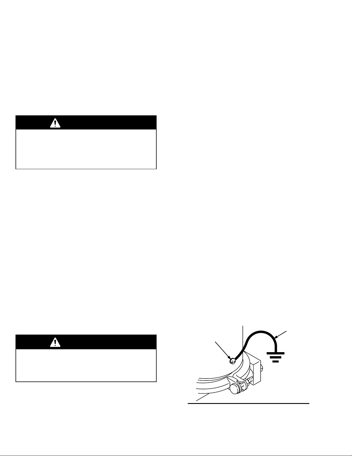
D Surge suppressor: Secure a ground wire (Y) to the
surge suppressor with the grounding screw (Z)
located on the side of the housing. See Fig. 1.
Connect the clamp end of the ground wire to a true
earth ground. To order a ground wire and clamp,
order Part No. 208950.
3. Open the dispensing valve, if used.
4. Open the fluid drain valve to relieve all fluid
pressure; have a container ready to catch the
drainage.
Fluid Compatibility
Be sure all fluids and solvents used are chemically
compatible with the wetted parts and non-wetted parts
shown in the Technical Data section on page 16.
Failure of the diaphragm may cause non-wetted parts
to be exposed to fluid. Always read the fluid and
solvent manufacturer’s literature before using them
with this equipment.
Grounding
WARNING
This equipment must be grounded. Read and
carefully follow the text of FIRE AND EXPLOSION
HAZARD on page 3 before operating the surge
suppressor.
D Air and fluid hoses: Use only grounded hoses with
a maximum of 500 ft (150 m) combined hose length
to ensure grounding continuity.
D Air compressor: Follow the manufacturer’s
recommendations.
D All solvent pails used when flushing: Follow the
local code. Use only metal pails, which are
conductive. Do not place the pail on a
nonconductive surface, such as paper or
cardboard, which interrupts the grounding
continuity.
D Fluid supply container: Follow the local code.
Y
Z
Static electricity is created by the fluid flowing through
the pump and hose. If the equipment is not properly
grounded, sparking may occur, and the system may
become hazardous. Sparks can ignite fumes from
solvents and the fluid being pumped, dust particles,
4 308178
Fig. 1
0942
Page 5
Installation
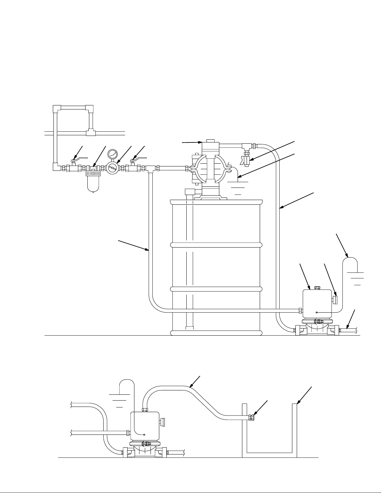
The installation shown below is only a guide for selecting and installing system components; it is not an actual
system design. Contact your Graco distributor for assistance in planning a system to suit your needs.
KEY
A Surge suppressor
B Air pressure gauge
C Fluid supply line
D Fluid outlet line
E Air supply line
F Husky 715 pump
G Fluid drain valve
H Bleed-type master air valve
(required for pump and surge
suppressor)
HJKL
F
J Air regulator
K Air Filter
L Bleed-type master air valve
(for accessories)
M Surge suppressor ground wire
(required)
N Pump ground wire
(required)
G
N
C
E
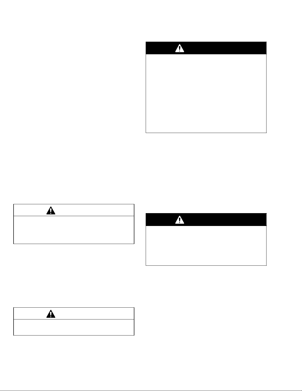
DETAIL A: Venting Exhaust Air to a Remote Container
grounded air exhaust hose
muffler
M
AB
D
container
for remote
air exhaust
308178
0906
5
Page 6
Installation
General Information
The surge suppressor uses air pressure and a
diaphragm to maintain a consistent fluid outlet
pressure from a double diaphragm or low-pressure
reciprocating pump. During normal flow, the
suppressor air pressure and fluid pressure are in
equilibrium. A sharp increase in fluid pressure causes
the air inlet port to open, increasing air pressure on the
diaphragm and returning the system to equilibrium.
Conversely, a sharp decrease in fluid pressure causes
the air exhaust port to open, decreasing air pressure
on the diaphragm and allowing the system to return to
equilibrium.
Installation
1. Read this entire manual before installing or
operating the surge suppressor.
2. The surge suppressor fluid inlet must be
connected to the pump’s fluid outlet. If the pump
is aluminum or steel, the surge suppressor may
be plumbed directly to the outlet, using 3/4 npt
fittings. If the pump is acetal or polypropylene,
place the surge suppressor on the floor or some
other solid, level surface near the pump, and
connect the surge suppressor inlet to the pump
outlet with a 3/4” ID hose and 3/4 npt fittings.
CAUTION
Air Exhaust Ventilation
WARNING
Be sure to read TOXIC FLUID HAZARD and FIRE
AND EXPLOSION HAZARD on page 3, before
operating this equipment.
Be sure the system is properly ventilated for your
type of installation. When pumping flammable or
hazardous fluids, you must vent the surge suppressor exhaust air to a safe place, away from people,
animals, food handling areas, and all sources of
ignition. If the diaphragm ruptures, the fluid will be
exhausted along with the air. Place a container at
the end of the air exhaust line to catch the fluid.
See Detail A on page 5.
The minimum size for the air exhaust hose is 3/8 in.
(10 mm) ID x 15 ft (4.6 m). If a longer hose is required,
use a larger diameter hose.
1. Remove the muffler from the surge suppressor
exhaust port. Install an exhaust hose in the
exhaust port, and connect the muffler to the other
end of the hose. Avoid sharp bends or kinks in the
hose. See Detail A on page 5.
2. Place a container at the end of the air exhaust line
to catch fluid in case the diaphragm ruptures.
Do not plumb the surge suppressor directly onto the
fluid outlet of an acetal or polypropylene pump.
Those pumps cannot support the weight of the
suppressor and will suffer damage or rupture.
3. Connect an air line from the pump’s air regulator to
the air inlet of the surge suppressor. In systems
using a 1:1 ratio pump, the air pressure supplied to
the suppressor will be the same as that supplied to
the pump.
4. Use a compatible, liquid thread sealant on all male
threads. Tighten all connections firmly to avoid air
or fluid leaks.
CAUTION
To avoid pump damage, do not overtighten the
fittings to the pump.
WARNING
Never operate the surge suppressor without the
muffler or an air exhaust line installed in the air
exhaust port. If the air exhaust port is left open and
the diaphragm shaft works loose from the bolt, the
shaft could be propelled out of the housing, causing injury.
6 308178
Page 7

Operation and Maintenance
Operating the Surge Suppressor
1. Be sure the system is properly grounded. Read
and follow FIRE AND EXPLOSION HAZARD, on
page 3.
2. Check all fittings to be sure they are tight. Be sure
to use a compatible liquid thread sealant on all
male threads, and do not overtighten the fittings
into the pump.
3. Check that the muffler or air exhaust line is
securely connected to the air exhaust port on the
top of the housing.
WARNING
Never operate the surge suppressor without the
muffler or an air exhaust line installed in the air
exhaust port. If the air exhaust port is left open and
the diaphragm shaft works loose from the bolt, the
shaft could be propelled out of the housing, causing injury.
4. Start the pump as explained in your separate
pump manual. In systems using a 1:1 ratio pump,
the air pressure supplied to the suppressor will be
the same as that supplied to the pump.
5. Allow the pump to cycle slowly until all air is
pushed out of the surge suppressor and lines, and
the pump is primed. The system is now ready for
normal operation.
WARNING
To prevent overpressurization of the surge suppressor, never exceed 100 psi (0.7 MPa, 7 bar)
fluid inlet pressure or 100 psi (0.7 MPa, 7 bar) air
inlet pressure. In systems using pumps with a ratio
greater than 1:1, reduce the air inlet pressure to
the pump as necessary to keep the fluid and air
inlet pressures to the surge suppressor within
these limits.
CAUTION
In systems using pumps with a ratio greater than 1:1,
fluid may escape into the surge suppressor air line
and contaminate the air supply if the diaphragm fails.
Installation of a check valve in the air line will prevent
fluid contamination of the air line.
Flushing the System
Flush the system regularly, using a compatible solvent.
Do not allow fluid to dry in the pump or surge
suppressor. Always flush the pump and surge
suppressor before storing them for any length of time.
Place the pump suction tube in the solvent container.
Run the pump long enough to thoroughly clean it, the
surge suppressor, hoses, and any guns or valves used
in the system. Close the pump air regulator. Remove
the suction hose from the solvent.
NOTES:
When using a pump with a ratio greater than 1:1, the
air pressure supplied to the surge suppressor and the
air pressure supplied to the pump must be at the same
ratio as the pump to prevent overpressurization of the
surge suppressor. See the following examples.
D In a system using a 2:1 ratio pump, air pressure
supplied to the surge suppressor should be twice
as high as air pressure to the pump. If the air
pressure supplied to the pump is 50 psi (0.34 MPa,
3.4 bar), you should supply 100 psi (0.7 MPa,
7 bar) air pressure to the surge suppressor.
D In a system using a 4:1 ratio pump, air pressure
supplied to the surge suppressor should be four
times as high as air pressure to the pump. If the
air pressure supplied to the pump is 25 psi
(0.17 MPa, 1.7 bar), you should supply 100 psi
(0.7 MPa, 7 bar) air pressure to the surge
suppressor.
Shutdown
Remove the suction hose from the fluid container and
run the pump until the fluid is forced out of the system.
Then shut off the air supply immediately.
308178
7
Page 8

Troubleshooting
WARNING
To reduce the risk of serious injury whenever you
are instructed to relieve pressure, always follow the
Pressure Relief Procedure on page 4.
Relieve the pressure.
Check all possible problems and causes before
disassembling the pump or surge suppressor.
PROBLEM
Surge suppressor operates
erratically
Air bubbles in fluid Fluid supply line loose Tighten.
Fluid in exhaust air Diaphragm (13 or 21[) ruptured Replace. See page 9.
CAUSE SOLUTION
Clogged air line or air inlet Inspect; clear.
Air line connected to pressure gauge
port
Clogged fluid supply line, fluid inlet or
fluid outlet
Diaphragm (13 or 21[) ruptured Replace. See page 9.
Unbalanced air pressures between
pump and surge suppressor
Diaphragm (13 or 21[) ruptured Replace. See page 9.
Manifold o-rings (16) leaking Replace. See page 10.
Connect air line to air inlet
(see page 11).
Inspect; clear.
Ratio of air inlet pressure to surge
suppressor and air inlet pressure to
pump must be the same as pump ratio, but air pressure to surge suppressor must never exceed 100 psi
(0.7 MPa, 7 bar). See page 7.
Diaphragm plates (12 or 32) loose or
damaged
Damaged shaft (11) or shaft o-rings
(19)
Pump leaks air or fluid from cover (7) V-clamp (6) is loose Tighten V-clamp. See page 9.
[ Ref. No. 21, the PTFE diaphragm, is used only in Surge Suppressor Models 224892 and 224894.
Tighten or replace. See page 9.
Replace. See page 9.
8 308178
Page 9

Service
Servicing the Shaft O-Rings
1. Relieve the pressure.
WARNING
To reduce the risk of serious injury whenever you
are instructed to relieve pressure, always follow the
Pressure Relief Procedure on page 4.
2. Place a container under the surge suppressor,
disconnect the hoses, and turn the surge
suppressor on end to drain the fluid.
3. Remove the v-clamp (6). See the Parts Drawing
on page 12.
4. Separate the housing (8) from the cover (7) to
expose the diaphragm and shaft assembly. Pull
the diaphragm and shaft out of the housing. See
Fig. 2.
5. Remove the three o-rings (19) from the shaft (11).
6. Lubricate the three new o-rings (19*) with
lithium-based grease and install them in the
grooves on the shaft.
Servicing the Diaphragm and Shaft
NOTE: Diaphragm Repair Kits are available. See page
14. Parts included in the kits are marked with
asterisks. The kits include some parts which are not
used on the surge suppressor. Use all the applicable
parts in the kit for the best results.
1. Relieve the pressure.
WARNING
To reduce the risk of serious injury whenever you
are instructed to relieve pressure, always follow the
Pressure Relief Procedure on page 4.
2. Place a container under the surge suppressor,
disconnect the hoses, and turn the surge
suppressor on end to drain the fluid.
3. Remove the v-clamp (6). See the Parts Drawing
on page 12.
4. Separate the housing (8) from the cover (7) to
expose the diaphragm and shaft assembly. Pull
the diaphragm and shaft out of the housing. See
Fig. 2.
7. Lubricate the inner diameter of the housing (8) with
lithium-based grease. Slide the shaft and
diaphragm assembly into the housing (8). Place
the cover (7) on the housing (8).
8. Position the clamp (6) around the housing (8) and
cover (7). Apply thread lubricant to the threads of
the v-clamp, secure with the nuts, and torque to 6
to 10 ft-lb (1.4 to 13.6 N.m). See the Parts
Drawing on page 12.
5. Hold the bolt (14) steady with a wrench. Wrap a
rag around the shaft (11) to protect it, then
unscrew the shaft from the bolt using locking
pliers. Remove the nut (31), upper diaphragm
plate (32*), diaphragm (13), PTFE diaphragm
(Models 224892 and 224894 only), lower
diaphragm plate (12), and o-ring (15) from the bolt.
Clean and inspect all parts for wear or damage.
308178
9
Page 10

Service
6. Place the o-ring (15*) on the bolt (14). Install the
lower diaphragm plate (12), with the flat side facing
down.
7. Install the diaphragm (13**), making certain that
the side marked AIR SIDE is facing up on the bolt.
On Models 224892 and 224894 only, install the
PTFE diaphragm (21**) first, then the backup
diaphragm (13**).
8. Install the upper diaphragm plate (32*) with the flat
side facing up. Apply thread sealant to the bolt
(14). Hold the bolt steady with a wrench, and
screw the nut (31) onto the bolt (14). Torque to 5 to
7 ft-lb (7 to 10 N-m).
9. Wrap the shaft (11) with a rag to protect it, and use
locking pliers to screw the shaft onto the bolt (14).
Torque to 10 to 15 in-lb (1.1 to 1.7 N-m).
10. Lubricate the inner diameter of the housing (8) with
lithium-based grease. Slide the shaft and
diaphragm assembly into the housing (8). Place
the cover (7) on the housing (8).
11. Position the clamp (6) around the housing (8) and
cover (7). Apply thread lubricant to the threads of
the v-clamp, secure with the nuts, and torque to 6
to 10 ft-lb (8 to 14 N.m). See the Parts Drawing
on page 12.
Servicing the Fluid Inlet and Outlet
NOTE: Repair Kits are available to service the internal
parts of the fluid inlet and outlet. See page 14 for
ordering information. Parts included in the kits are
marked with three asterisks, for example (16***). The
kits include some parts which are not used on the
surge suppressor. Use all the applicable parts in the kit
for the best results.
1. Relieve the pressure.
WARNING
To reduce the risk of serious injury whenever you
are instructed to relieve pressure, always follow the
Pressure Relief Procedure on page 4.
2. Place a container under the surge suppressor,
disconnect the hoses, and turn the surge
suppressor on end to drain the fluid.
3. Remove the bolts (2), lockwashers (3), and nuts
(1) holding one manifold (9) to the cover (7).
Repeat for the other side. See Fig. 2.
4. Pull the two o-rings (16), guide (18) and stop (17)
out of the cover (7). Repeat for the other side.
Clean and inspect all parts for wear or damage.
5. Push one o-ring (16***) all the way into the cavity
of the cover (7). Install the stop (17***) with the
beveled side facing inward. Install the guide (18***)
with the flat end facing inward, then install the
second o-ring (16***) around the outer edge of the
guide. Repeat for the other side.
6. Install the manifold (9) on the cover (7) with the
chamfer facing outward. Secure with the bolts (2),
lockwashers (3), and nuts (1). Torque to 3 to 6 ft-lb
(4 to 8 N.m). Repeat for the other side.
10 308178
Page 11

Service
diameter of housing
(8) with lithium-based
Fig. 2
Lubricate inner
grease
Air inlet
1/4 npt(f)
9
Chamfer
faces out
8
6
7
***16 16***
***18
Flat end
faces
inward
21**
(models
224892 and
224894 only)
17***
Beveled side
faces inward
12*
Flat side
faces down
*15**
14*
Apply sealant to
threads.
19*
Lubricate with
lithium-based grease
11
Torque to 10 to 15 in-lb
(1.1 to 1.7 N-m)
31
Torque to 5 to 7 ft-lb
(7 to 10 N-m)
32*
Flat side faces up
13**
2
1
3
Torque to
3 to 6 ft-lb
(4 to 8 N-m)
0905
308178
11
Page 12

Parts Drawing
Model 224892, Series A, aluminum surge suppressor with PTFE diaphragm
Model 224893, Series A, aluminum surge suppressor with buna–N diaphragm
Model 224894, Series C, stainless steel surge suppressor with PTFE diaphragm
Model 224895, Series C, stainless steel surge suppressor with buna–N diaphragm
10
Torque to
10 to 15 in-lb
(1.1 to 1.7 N.m)
8
6
33
Apply sealant tape to threads
30
29
Torque to 6 to 10 ft-lb
(8 to 14 N.m)
Lubricate with
lithium-base grease
Torque to
10 to 15 in-lb
(1.1 to 1.7 N.m)
Torque to
5 to 7 ft-lb
(7 to 10 N.m)
Flat side faces up
(PTFE, 183542) **13
(buna–N, 190148)
Used on Models 224892 and
(108839) **21
224894 only
Flat side faces down
(110004) *15**
Apply sealant to threads
*32
*12
*14
19
11
31
4
* The replacements for these parts are available
in Diaphragm Plate Kit 239158. See page 14.
Purchase this kit separately.
** The replacements for these parts are available
in Diaphragm Repair Kits D05001 and D05007.
See page 14. Purchase the applicable kit
separately.
*** The replacements for these parts are available
in Repair Kits D05210, D05310, and D05270.
See page 14. Purchase the applicable kit
separately.
18*** (acetal, 186692)
(sst, 187243)
17*** (acetal, 186691)
(sst, 187242)
2
Torque to
3 to 6 ft-lb
(4 to 8 N.m)
3
9
16*** (110636)
Chamfer
faces out
12 308178
1
7
05476
Page 13

Parts Lists
Model 224892, Series A
aluminum surge suppressor with PTFE diaphragm
Model 224893, Series A
aluminum surge suppressor with buna–N
diaphragm
Ref Part
No. No. Description Qty
1 100307 NUT, hex; 3/8–16 unc–2b 4
2 100003 BOLT, cap, hex hd;
3/8–16 unc–2a x 1.5” long 4
3 111203 LOCKWASHER; 3/8” size 4
4 112499 NUT, hex; 5/16 18–8;
silver-plate sst 1
6 189540 V-CLAMP; sst 1
7 185622 COVER; aluminum 1
8 187476 HOUSING; aluminum 1
9 187477 MANIFOLD; aluminum 2
10 111530 MUFFLER 1
11 187475 SHAFT; acetal 1
12 191837* PLATE, diaphragm, fluid side; sst 1
13 183542** DIAPHRAGM, backup;
polyurethane;
used on Model 224892 only 1
190148** DIAPHRAGM; buna–N;
used on Model 224893 only 1
14 113901* SCREW, cap, hex hd;
1/4–20 unc–2a x 1.25” long; sst 1
15 *110004** O-RING; PTFE 1
16 110636*** O-RING; PTFE;
used on Model 224892 only 4
110636*** O-RING; buna–N;
used on Model 224893 only 4
17 186692*** STOP, ball; acetal 2
18 186691*** GUIDE, ball; acetal 2
19 111532 O-RING; buna–N 3
21 108839** DIAPHRAGM; PTFE;
used on Model 224892 only 1
29 100264 SCREW, machine, pan hd;
10–24 unc–2a x 5/16” long 1
30 100718 LOCKWASHER, int tooth; no. 10 1
31 102025 NUT, hex; 1/4–20; sst 1
32 191741* PLATE, diaphragm, air side; SST 1
33 100721 PLUG, pipe, headless; 1/4 npt 1
* The replacements for these parts are available in
Diaphragm Plate Kit 239158. See page 14. Purchase the
kit separately.
** The replacements for these parts are available in
Diaphragm Repair Kits D05001 and D05007. See page 14.
Purchase the applicable kit separately.
*** The replacements for these parts are available in Repair
Kits D05210, D05310, and D05270. See page 14.
Purchase the applicable kit separately.
Model 224894, Series C
stainless steel surge suppressor with PTFE
diaphragm
Model 224895, Series C
stainless steel surge suppressor with buna–N
diaphragm
Ref Part
No. No. Description Qty
1 100307 NUT, hex; 3/8–16 unc–2b 4
2 100003 BOLT, cap, hex hd;
3/8–16 unc–2a x 1.5” long 4
3 111203 LOCKWASHER; 3/8” size 4
4 112499 NUT, hex; 5/16 18–8;
silver-plate sst 1
6 189540 V-CLAMP; sst 1
7 187241 COVER; stainless steel 1
8 187476 HOUSING; aluminum 1
9 187564 MANIFOLD; stainless steel 2
10 111530 MUFFLER 1
11 187475 SHAFT; acetal 1
12 16M908* PLATE, diaphragm, fluid side;
sst machined 1
13 183542** DIAPHRAGM, backup;
polyurethane;
used on Model 224894 only 1
190148** DIAPHRAGM; buna–N;
used on Model 224895 only 1
14 113901* SCREW, cap, hex hd;
1/4–20 unc–2a x 1.25” long; sst 1
15 *110004** O-RING; PTFE 1
16 110636*** O-RING; PTFE;
used on Model 224894 only 4
110636*** O-RING; buna–N;
used on Model 224895 only 4
17 187243*** STOP, ball; stainless steel 2
18 187242*** GUIDE, ball; stainless steel 2
19 111532 O-RING; buna–N 3
21 108839** DIAPHRAGM; PTFE;
used on Model 224894 only 1
29 100264 SCREW, machine, pan hd;
10–24 unc–2a x 5/16” long 1
30 100718 LOCKWASHER, int tooth; no. 10 1
31 102025 NUT, hex; 1/4–20; sst 1
32 191741* PLATE, diaphragm, air side; SST 1
33 100721 PLUG, pipe, headless; 1/4 npt 1
* The replacements for these parts are available in
Diaphragm Plate Kit 239158. See page 14. Purchase the
kit separately.
** The replacements for these parts are available in
Diaphragm Repair Kits D05001 and D05007. See page 14.
Purchase the applicable kit separately.
*** The replacements for these parts are available in Repair
Kits D05210, D05310, and D05270. See page 14.
Purchase the applicable kit separately.
308178
13
Page 14

Repair Kits
Repair Kits must be purchased separately.
Use only genuine Graco parts and accessories.
The Ref. No. shown in the kits below correspond to the reference numbers used in the Parts List on page 13. For the
best results, use all the parts in the kit, even if the old parts still look good.
PTFE Diaphragm Kit D05001
For Models 224892 and 224894. Includes enough parts
to service the surge suppressor twice.
Ref
No. Part No. Description Qty.
13 183542 DIAPHRAGM, backup;
polyurethane 2
15 110004 PACKING, o-ring 2
16 110636 PACKING, o-ring 8
] 191779 BEARING; acetal 2
] 113704 PACKING, o-ring; FKM 2
21 108839 DIAPHRAGM; PTFE 2
] These parts are not used with the surge suppressor.
Buna-N Diaphragm Kit D05007
For Models 224893 and 224895. Includes enough parts
to service the surge suppressor twice.
Ref
No. Part No. Description Qty.
13 190148 DIAPHRAGM; buna–N 2
15 110004 PACKING, o-ring 2
16 110636 PACKING, o-ring 8
] 191779 BEARING; acetal 2
] 113704 PACKING, o-ring; FKM 2
] These parts are not used with the surge suppressor.
PTFE Ball Repair Kit D05210
For Model 224892 only. Includes enough parts to service
the surge suppressor twice.
Ref
No. Part No. Description Qty.
15 110004 PACKING, o-ring 2
16 110636 O-RING; PTFE 8
17 186691 GUIDE, ball; black acetal 4
18 186692 STOP, ball; black acetal 4
] 108639 BALL; 0.75”; PTFE 4
] These parts are not used with the surge suppressor.
Buna-N Ball Repair Kit D05270
For Model 224893 only. Includes enough parts to service
the surge suppressor twice.
Ref
No. Part No. Description Qty.
15 110004 PACKING, o-ring 2
16 110636 PACKING, o-ring 8
17 186691 GUIDE, ball; black acetal 4
18 186692 STOP, ball; black acetal 4
] 108944 BALL; 0.75”; buna–N 4
] These parts are not used with the surge suppressor.
PTFE Ball Repair Kit D05310
For Model 224894 only. Includes enough parts to service
the surge suppressor twice.
Ref
No. Part No. Description Qty.
15 110004 PACKING, o-ring 2
16 110636 O-RING; PTFE 8
17 187242 GUIDE, ball; stainless steel 4
18 187243 STOP, ball; stainless steel 4
] 108639 BALL; 0.75”; PTFE 4
] These parts are not used with the surge suppressor.
Buna-N Ball Repair Kit D05370
For Model 224895 only. Includes enough parts to service
the surge suppressor twice.
Ref
No. Part No. Description Qty.
15 110004 PACKING, o-ring 2
16 110636 PACKING, o-ring 8
17 187242 GUIDE, ball; stainless steel 4
18 187243 STOP, ball; stainless steel 4
] 108944 BALL; 0.75”; buna–N 4
] These parts are not used with the surge suppressor.
] These parts are not used with the surge suppressor.
Diaphragm Plate Kit 239158
For all models.
Ref
No. Part No. Description Qty.
12 16M908 PLATE, diaphragm, fluid,
sst machined 1
14 113901 SCREW, flange, hex-head;
1/4–20 x 1.25 1
15 110004 PACKING, o-ring; PTFE 1
32 191741 PLATE, diaphragm, air side 1
14 308178
Page 15

Dimensional Drawing
air exhaust muffler: 1/2 npt
air inlet:
1/4 npt(f)
height:
8.78 in.
(223 mm)
fluid outlet:
3/4 npt(f)
width across clamp:
7.38 in. (187.5 mm)
fluid inlet:
3/4 npt(f)
inlet-to-outlet length:
7.74 in. (196.6 mm)
total length:
8.40 in. (213.4 mm)
0903
308178
15
Page 16

Technical Data
Maximum fluid working pressure 100 psi (0.7 MPa, 7 bar). . . . . . . . . . . . . . . . . . . . . . . . . . . . . . . . . . . . . . . . . . . . . . . . . . .
Air pressure operating range 25 to 100 psi (0.18 to 0.7 MPa, 1.75 to 7 bar). . . . . . . . . . . . . . . . . . . . . . . . . . . . . . . . . . .
Maximum free flow delivery 16 gpm (60 l/min). . . . . . . . . . . . . . . . . . . . . . . . . . . . . . . . . . . . . . . . . . . . . . . . . . . . . . . . . . . . .
Air inlet 1/4 npt(f). . . . . . . . . . . . . . . . . . . . . . . . . . . . . . . . . . . . . . . . . . . . . . . . . . . . . . . . . . . . . . . . . . . . . . . . . . . . . . . . . . . . .
Air exhaust 1/2 npt(f). . . . . . . . . . . . . . . . . . . . . . . . . . . . . . . . . . . . . . . . . . . . . . . . . . . . . . . . . . . . . . . . . . . . . . . . . . . . . . . . . .
Fluid inlet. 3/4 npt(f). . . . . . . . . . . . . . . . . . . . . . . . . . . . . . . . . . . . . . . . . . . . . . . . . . . . . . . . . . . . . . . . . . . . . . . . . . . . . . . . . . .
Fluid outlet 3/4 npt(f). . . . . . . . . . . . . . . . . . . . . . . . . . . . . . . . . . . . . . . . . . . . . . . . . . . . . . . . . . . . . . . . . . . . . . . . . . . . . . . . . .
Wetted parts Model 224892: acetal, aluminum, PTFE,. . . . . . . . . . . . . . . . . . . . . . . . . . . . . . . . . . . . . . . . . . . . . . . . . . . . . .
316 stainless steel
Model 224893: acetal, aluminum, PTFE,
buna–N, 316 stainless steel
Model 224894: 316 stainless steel, PTFE
Model 224895: 316 stainless steel, buna–N, PTFE
Non-wetted Parts Models 224892 and 224894:. . . . . . . . . . . . . . . . . . . . . . . . . . . . . . . . . . . . . . . . . . . . . . . . . . . . . . . . . . . .
acetal, aluminum, buna–N,
polyurethane, bronze, plated steel,
polyester (labels)
Models 224893 and 224895:
acetal, aluminum, buna–N,
bronze, plated steel, polyester (labels)
Weight Models 224892 and 224893: 10 lb (4.6 kg). . . . . . . . . . . . . . . . . . . . . . . . . . . . . . . . . . . . . . . . . . . . . . . . . . . . . . . . .
Models 224894 and 224895: 14 lb (6.4 kg)
16 308178
Page 17

Notes
308178
17
Page 18

Graco Standard Warranty
Graco warrants all equipment manufactured by Graco and bearing its name to be free from defects in material and workmanship on the
date of sale to the original purchaser for use. With the exception of any special, extended, or limited warranty published by Graco,
Graco will, for a period of twelve months from the date of sale, repair or replace any part of the equipment determined by Graco to be
defective. This warranty applies only when the equipment is installed, operated and maintained in accordance with Graco’s written
recommendations.
This warranty does not cover, and Graco shall not be liable for general wear and tear, or any malfunction, damage or wear caused by
faulty installation, misapplication, abrasion, corrosion, inadequate or improper maintenance, negligence, accident, tampering, or
substitution of non–Graco component parts. Nor shall Graco be liable for malfunction, damage or wear caused by the incompatibility of
Graco equipment with structures, accessories, equipment or materials not supplied by Graco, or the improper design, manufacture,
installation, operation or maintenance of structures, accessories, equipment or materials not supplied by Graco.
This warranty is conditioned upon the prepaid return of the equipment claimed to be defective to an authorized Graco distributor for
verification of the claimed defect. If the claimed defect is verified, Graco will repair or replace free of charge any defective parts. The
equipment will be returned to the original purchaser transportation prepaid. If inspection of the equipment does not disclose any defect
in material or workmanship, repairs will be made at a reasonable charge, which charges may include the costs of parts, labor, and
transportation.
THIS WARRANTY IS EXCLUSIVE, AND IS IN LIEU OF ANY OTHER WARRANTIES, EXPRESS OR IMPLIED, INCLUDING BUT
NOT LIMITED TO WARRANTY OF MERCHANTABILITY OR WARRANTY OF FITNESS FOR A PARTICULAR PURPOSE.
Graco’s sole obligation and buyer’s sole remedy for any breach of warranty shall be as set forth above. The buyer agrees that no other
remedy (including, but not limited to, incidental or consequential damages for lost profits, lost sales, injury to person or property, or any
other incidental or consequential loss) shall be available. Any action for breach of warranty must be brought within two (2) years of the
date of sale.
Graco makes no warranty, and disclaims all implied warranties of merchantability and fitness for a particular purpose in connection
with accessories, equipment, materials or components sold but not manufactured by Graco. These items sold, but not manufactured
by Graco (such as electric motors, switches, hose, etc.), are subject to the warranty, if any, of their manufacturer. Graco will provide
purchaser with reasonable assistance in making any claim for breach of these warranties.
In no event will Graco be liable for indirect, incidental, special or consequential damages resulting from Graco supplying equipment
hereunder, or the furnishing, performance, or use of any products or other goods sold hereto, whether due to a breach of contract,
breach of warranty, the negligence of Graco, or otherwise.
FOR GRACO CANADA CUSTOMERS
The parties acknowledge that they have required that the present document, as well as all documents, notices and legal proceedings
entered into, given or instituted pursuant hereto or relating directly or indirectly hereto, be drawn up in English. Les parties
reconnaissent avoir convenu que la rédaction du présente document sera en Anglais, ainsi que tous documents, avis et procédures
judiciaires exécutés, donnés ou intentés à la suite de ou en rapport, directement ou indirectement, avec les procedures concernées.
Graco Information
For the latest information about Graco products, visit www.graco.com.
TO PLACE AN ORDER, contact your Graco distributor or call to identify the distributor closest to you:
Phone: 612–623–6921 or Toll Free: 1–800–328–0211 Fax: 612–378–3505
All written and visual data contained in this document reflects the latest product information available at the time of publication.
Graco reserves the right to make changes at any time without notice.
18 308178
Original Instructions. This manual contains English. MM 308178
International Offices: Belgium, China, Japan, Korea
GRACO INC. AND SUBSIDIARIES
Copyright 1991, Graco Inc. All Graco manufacturing locations are registered to ISO 9001.
Graco Headquarters: Minneapolis
S P.O. BOX 1441 S MINNEAPOLIS, MN 55440-1441 S USA
www.graco.com
Revised 1/2012
 Loading...