

Page 1
Instructions – Parts List
Parts
Mascott Equipment Co
Portland Seattle Pasco
(800) 452-5019 (800) 481-7311 (888) 450-7867
Air Filters, Lubricators,
and Kits
Maximum Temperature Range: 40–150_F (4–65_C)
Important Safety Instructions.
Read all warnings and instructions in this manual.
Save these instructions.
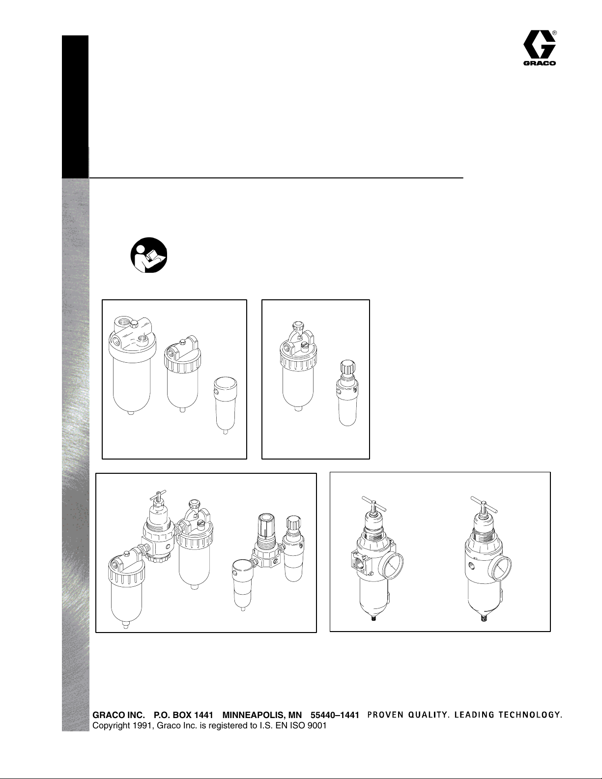
Air Filters
217074
106148
106149
106150
112859
110146
Air Lubricators
214847
214848
214849
237212
308169J
110148
Air Filter–Regulators–Lubricators
110150
217072
217073
GRACO INC. P.O. BOX 1441 MINNEAPOLIS, MN 55440–1441
Copyright 1991, Graco Inc. is registered to I.S. EN ISO 9001
110149
Integral Filter–Regulators
15C955
246947
246948
246946
Page 2

Air Filters
List of Models
Model
No.
110146 22 (0.62) Husky 715, Prince, Fast–Flo, Fast–Ball 1/4 npt 300 (21) 1 (30) 20
106148 77 (2.2) President, Fire–Ball, Monark 3/8 npt 250 (17.5) 5 (150) 20
106149 106 (3.0) Bulldog, Senator, Glutton 1/2 npt 250 (17.5) 8 (240) 20
217074 106 (3.0) Bulldog, Senator, Glutton 1/2 npt 250 (17.5) 8 (240) 40
106150 250 (7.0) King 3/4 npt 250 (17.5) 16 (480) 40
112859 350 (10.0) Premier 1 npt 250 (17.5) 16 (480) 40
Max.
SCFM
Pump/System
Application
Inlet/
Outlet
Maximum WPR*
psi (bar)
Bowl Capacity
oz (ml)
Filter
Micron
Air Lubricators
Model
No.
110148 12 (0.34) Husky, Prince, Fast–Flo, Fast–Ball 1/4 npt 300 (21) 1 (30)
214847 88 (2.5) President, Fire–Ball, Monark 3/8 npt 250 (17.5) 5 (150)
214848 127 (3.6) Bulldog, Senator, Glutton 1/2 npt 250 (17.5) 8 (240)
214849 290 (8.1) King 3/4 npt 250 (17.5) 16 (480)
237212 320 (9.2) Premier 1 npt 250 (17.5) 16 (480)
Max.
SCFM
Pump/System
Application
Inlet/
Outlet
Maximum WPR*
psi (bar)
Bowl Capacity
oz (ml)
Air Filter–Regulator–Lubricator Kit
(F–R–L)
Includes Maximum
Model
No.
110149 110146 110318 110148 110319 Husky 715, Prince, Fast-Flo, Fast-Ball 1/4 npt 300 (21)
110150 106148 110234 214847 101689 President, Fire–Ball, Monark, Standard 3/8 npt 250 (17.5)
217072 106149 104266 214848 101689 Bulldog, Senator, Glutton, Husky 1030 1/2 npt 250 (17.5)
217073 106150 207755 214849 101689 King 3/4 npt 250 (17.5)
FILTER REGULATOR LUBRICATOR GAUGE Pump/System
Application
Inlet/
Outlet
WPR*
psi (bar)
Integral Filter–Regulators
Maximum
Model
No.
246946 15C956 C36260 Husky 205, 307, 515/716 1/4 npt 250 (17.5)
246947 15C955 C36260 Husky 1040, 1590, and 2150 1/2 npt 250 (17.5)
246948 15C955 C36260 Husky 3275 3/4 npt 250 (17.5)
15C955 n/a n/a n/a 1/2 npt 250 (17.5)
2 308169
FILTER GAUGE Pump/System
Application
Inlet/
Outlet
WPR*
psi (bar)
Page 3
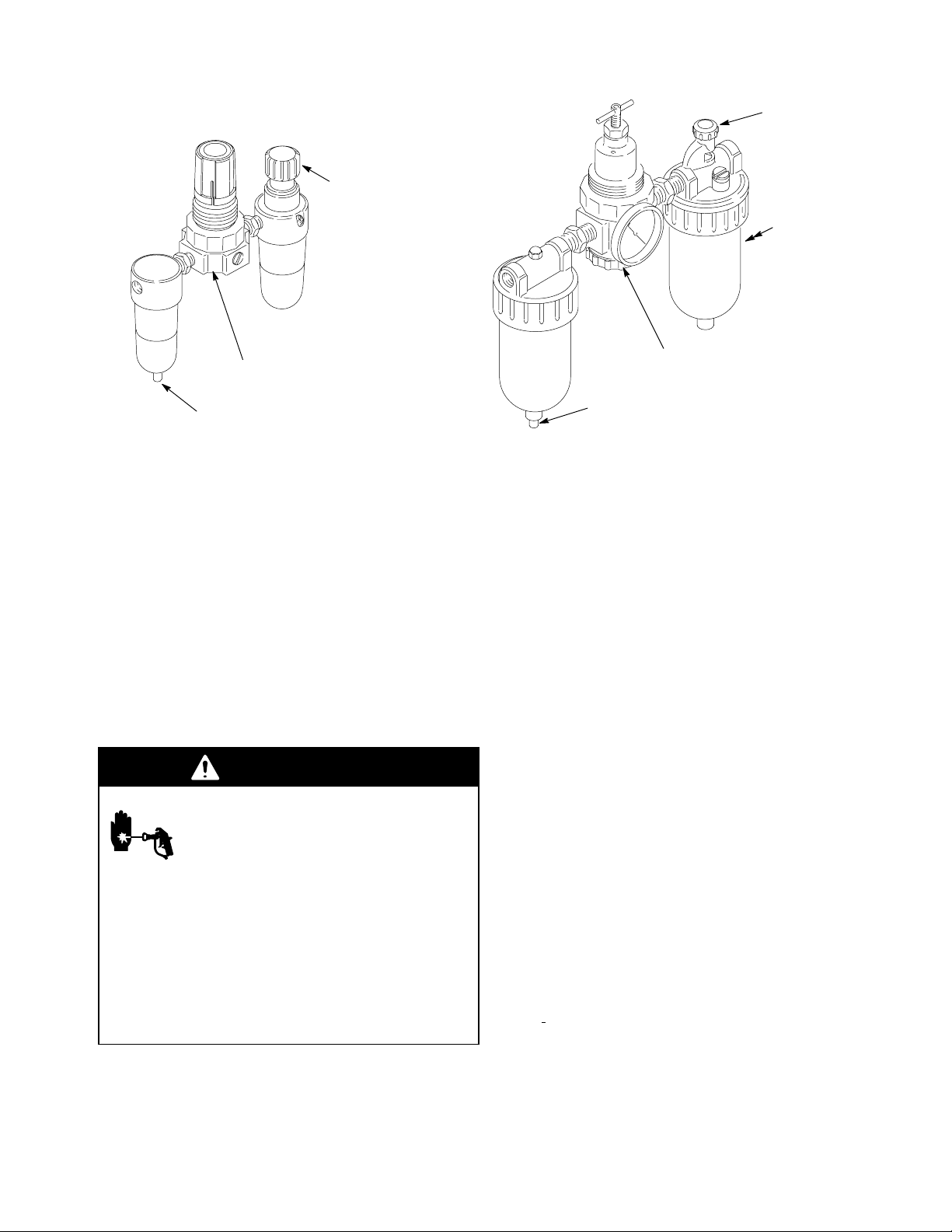
Installation
Model 110149 Model 110150
217072
217073
LUBRICATOR
ADJUSTMENT
KNOB
AIR REGULATOR
AIR FILTER DRAIN
Before installing any air line components, blow out the
pipe line to remove scale and other debris. Use pipe compound or tape sparingly and only on male threads.
Install the components in the pipe line so the flow is in the
direction of the arrow stamped on the body.
Locate the air line component(s) as close as possible to
the equipment it serves.
Install the air filter upstream from the regulator and/or lubricator.
To provide the user with a variety of assembly options, a
bleed–type master air valve is not included with FRL’s.
See Accessories on page 15 to order this valve. Another
bleed–type master air valve can be installed upstream
from the FRL to isolate it for servicing.
WARNING
Air Filter
Clean the air filter regularly to maximize filtering efficiency and to avoid excessive pressure drop. Drain contaminants from the bowl before it reaches the baffle level.
Open the drain to drain the bowl or fully relieve pressure
and remove the bowl. Use household soap and water or
denatured alcohol for cleaning. Use compressed air to
blow out the filter body. Wash the filter element and blow
it out from the inside. Clean the sight glass thoroughly. Do
not leave solvent residue in the sight glass, which may attack or weaken it. If the sight glass appears damaged by
the solvent, replace it immediately.
An automatic drain accessory, Part No. 106151, is available for most filters, except Model 110146. To install the
drain, fully relieve system pressure, remove the o–ring
and bowl. Remove the drain from the bowl and insert the
automatic drain in its place. Reassemble.
Skin Injection Hazard
To reduce the risk of serious bodily
injury, including skin injection, splashing
fluid in the eyes or on the skin, or injury
from the pump starting unexpectedly, be
sure your system includes a
bleed–type master air valve.Install the
air valve between the FRL outlet and the
device the FRL is serving. When
relieving system air pressure, close the
bleed–type master air valve to fully
relieve air pressure.
Mounting Air Accessories
Use a bracket to mount the air accessories to a wall or
cart. Do not hang the accessories directly off the air motor inlet, which could be damaged from the weight and
operating stress.
Regulator
The regulator reduces the air supply pressure to a specified, constant downstream pressure to maximize equipment performance. Preset pressures can be locked in.
See manual 308167 or 308168 (supplied with the FRL’s)
for complete air regulator information.
Lubricator
The lubricator meters oil into the moving air stream to lubricate air-operated motors. A manual adjustment in the
housing sets the oil drip rate into the air stream, which
can be monitored through a sight glass on most lubricators. One to two drops of oil a minute is a common adjustment. Use Graco motor oil, part no. 202659. All lubricators, except Model 110148, can be refilled with the
system pressurized. However, ALWAYS relieve the system pressure before removing the bowl for any reason.
LUBRICATOR
ADJUSTMENT
KNOB
LUBRICATOR
SIGHT
GLASS
(NOT VISIBLE FROM
THIS VIEW)
AIR REGULATOR
AIR FILTER DRAIN
3308169
Page 4
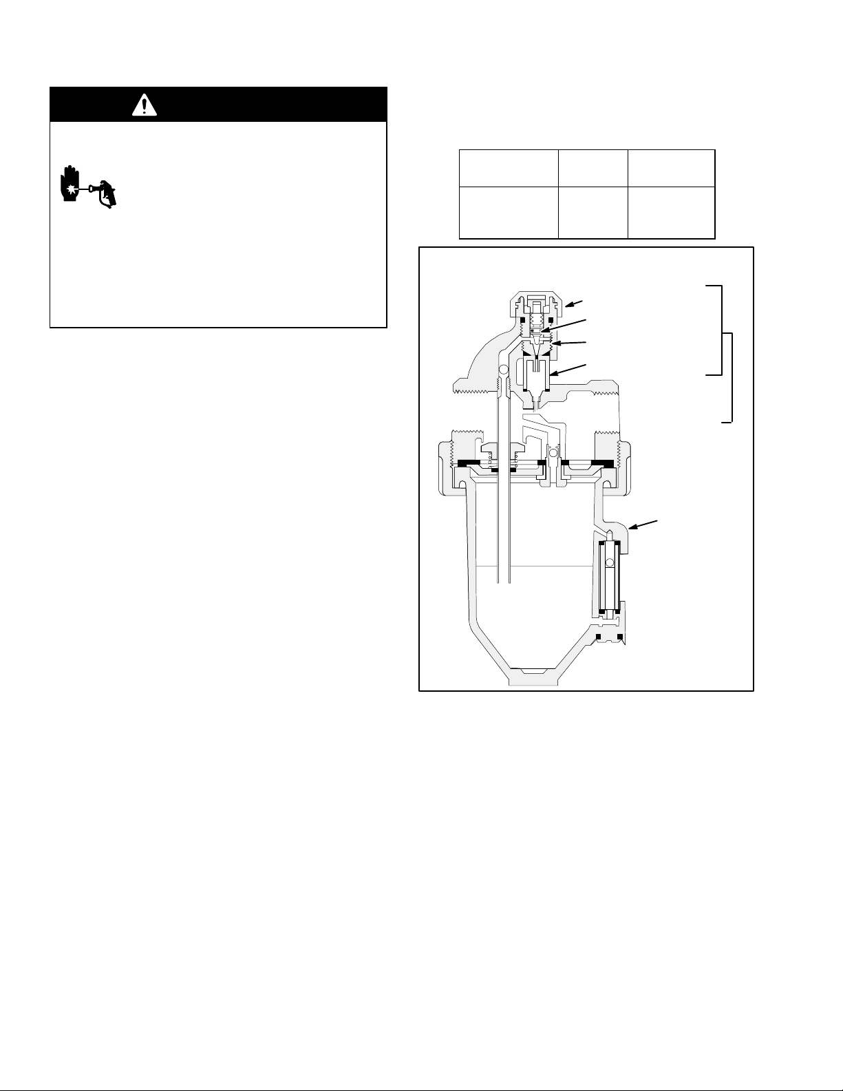
Service
WARNING
Relieve air and fluid pressure
before servicing the regulator, filter or
lubricator.
To reduce the risk of serious bodily injury, fluid injection, splashing in the eyes
or skin, injury from moving parts, ALWAYS open the bleed–type master air
valve (required) to relieve system air
pressure and trigger the gun or dispense valve and open any fluid drain
valves to relieve fluid pressure.
1. Disassemble the component. Refer to the illustrations on pages 4 and 5.
Repair Kits
Lubricator Repair Kits
For
Lubricator
214847
214848
214849
Lubricator 214847, 214848, 214849, 237212
Kit No. Description
102774 Repair Kit
ADJUSTABLE CAP
VALVE NEEDLE ASSY.
VALVE SEAT
FILLER PLUG
2. Use household soap and water or denatured
alcohol for cleaning. Wipe the parts clean with a
clean, soft, dry rag. Use compressed air to blow
dirt and contaminants out of the lubricator or filter
body.
3. Inspect all parts for wear or damage. Replace
damaged parts. Use all parts supplied with the kit.
NOTE: The chart identifies the available repair kits for the
air filters and lubricators covered in this manual. The cutaway drawings shown on pages 5 and 6 show the contents of the kits.
KIT 102774
BOWL
(see chart)
0940
4 308169
Page 5
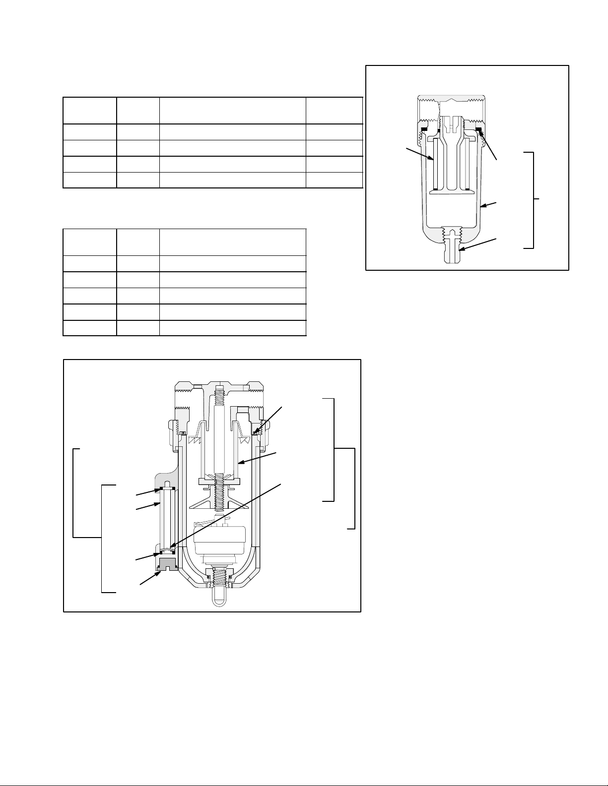
Service
Filter Elements & Bowl Seals
For
Filter
Kit No. Description Bowl Seal
Part No.
106149 108035 1/2 in., 20 micron filter element 162440
106150 106204 3/4 in., 40 micron filter element 104023
112859 ––––– 1 in., 40 micron filter element –––––
110146 111690 1/4 in., 20 micron filter element N/A
Sight Glass Kits
For
Kit No. Description
Filter
106148 104991 3/8 in. sight glass
106149 104992 1/2 in. sight glass
106150 104993 3/4 in. sight glass
112859 104993 1/2 in. sight glass
217074 106197 1/2 in. sight glass
Air Filter 110146
FILTER
ELEMENT
GASKET
BOWL
DRAIN
BOWL
KIT
0939
Air Filter 106148, 106149, 106150, 112859,
217074
SIGHT GLASS KIT
104991, 104992,
104993, 106197
O-RING
SIGHT
GLASS
O-RING
PLUG
BOWL SEAL KIT
106202,106204,
106205, 106206,
108034, 108035
0938
BOWL SEAL
FILTER
ELEMENT
INDICATOR
FLOAT
5308169
Page 6

Service
Filter Bowl Replacement Kits with Seal
For
Filter
116521 116672 3/4 in. port, bowl
15C955 116672 1/2 in. port, bowl
15C956 248085 1/4 in. port, bowl
Filter Element Kit with Gasket
For
Filter
116521 116635 3/4 in. 40 micron
15C955 116635 1/2 in. 40 micron
15C956 248087 1/4 in. 40 micron
Kit No. Description
w/sight glass
w/sight glass
w/sight glass
Kit No. Description
filter element
filter element
filter element
Regulator Repair Kit
For
Filter
116521 116634 3/4 in. valve and
15C955 116634 1/2 in. valve and
15C956 248086 1/4 in. valve and
Kit No. Description
diaphragm
diaphragm
diaphragm
6 308169
Page 7

Parts
3/8 npt(f)
2
1/4 npt(f)
OUTLET
4
OUTLET
1/4 npt(f)
INLET
3
1
5
Model 110149, Series A
Includes items 1–5
Ref
No. Part No. Description Qty
1 110146 FILTER 1
2 110318 REGULATOR (see 308167) 1
3 110148 LUBRICATOR 1
4 110321 MOUNTING BRACKET 1
5 110319 1/8 in. GAUGE 1
3/8 npt(f)
INLET
0926
4
2
1
Model 110150, Series B
Includes items 1–5
Ref
No. Part No. Description Qty
1 106148 FILTER 1
2 110234 REGULATOR (see 308167) 1
3 214847 LUBRICATOR 1
4 101689 1/4 in. GAUGE 1
3
7308169
Page 8

Parts
4
1/2 npt(f)
OUTLET
1/2 npt(f)
INLET
5
0926
2
1
Model 217072, Series A
Includes items 1–5
Ref
No. Part No. Description Qty
1 106149 FILTER 1
2 104266 REGULATOR (see 308167) 1
3 214848 LUBRICATOR 1
4 106145 MOUNTING BRACKET 2
5 101689 GAUGE 1
4
3/4 npt(f)
OUTLET
3/4 npt(f)
INLET
3
5
2
0926
3
1
Model 217073, Series A
Includes items 1–5
Ref
No. Part No. Description Qty
1 106150 FILTER 1
2 207755 REGULATOR (see 308167) 1
3 214849 LUBRICATOR 1
4 106145 MOUNTING BRACKET 2
5 101689 GAUGE 1
8 308169
Page 9

Parts
2
2
1
1
Model 15C955, 246947, and 246948
Model 246946
Ref
No. Part No. Description Qty
1 15C956 REGULATOR, filter, air; 1/4 npt 1
2 C36260 GAUGE, pressure, air 1
Ref
No. Part No. Description Qty
1 15C955 REGULATOR, filter, air 1/2 npt 1
Model 246947
116521 REGULATOR, filter, air 3/4 npt 1
Model 246948
2 C36260 GAUGE, pressure, air 1
Models 246947 and 246948 only
9308169
Page 10

Dimensions
Air Filter
Model
No.
110146 1/4 npt 1.6 (40) 4.0 (102) 3.6 (91)
106148 3/8 npt 2.5 (64) 6.0 (143) 3.1 (79)
106149 1/2 npt 3.3 (83) 6.8 (174 ) 6.3 (159)
217074 1/2 npt 3.0 (76) 7.5 (191) 6.6 (168)
106150 3/4 npt 4.0 (102) 8.8 (222) 7.8 (198)
112859 1 npt 4.5 (114) 8.8 (222) 7.9 (201)
Model 110146
B
C
A
Inlet/
Outlet
Width (A)
in. (mm)
Model 106148
106149
106150
112859
A
B
C
Height (B)
in. (mm)
Height (C)
in. (mm)
Model 217074
B
C
Lubricators
Model
No.
110148 1/4 npt 1.5 (39) 5.0 (126) 3.0 (76)
214847 3/8 npt 2.5 (64) 7.2 (182) 4.8 (122)
214848 1/2 npt 3.3 (83) 7.9 (201) 5.6 (142)
214849 3/4 npt 4.0 (103) 9.9 (251) 7.3 (184)
237212 1 npt 4.0 (103) 9.9 (251) 7.3 (184)
A
0929
0930
0932
Inlet/
Outlet
Width (A)
in. (mm)
Model 110148
B
C
Height (B)
in. (mm)
Height (C)
in. (mm)
Model 214847
214848
214849
237212
A
A
B
C
0934
0935
Integral Filter–Regulators
Model
No.
246946 1/4 npt 2–3/8
246947 1/2 npt 3.375
246948 3/4 npt 3.375
B
C
Models 15C955,
246947, 246948
A
Inlet/
Outlet
Width (A)
in. (mm)
(60.32)
(85.73)
(85.73)
Height (B)
in. (mm)
9.563
(242.87)
11.375
(288.93)
11.375
(288.93)
B
C
Model 246946
Height (C)
in. (mm)
4.938
(125.41)
6.5 (165)
6.5 (165)
A
TI3969
TI3970
10 308169
Page 11

Filter–Regulator–Lubricators
Dimensions
Model
No.
110149 1/4 npt 5.1 (130) 5.1 (130) 3.5 (89) 1.6 (40)
110150 3/8 npt 8.8 (222) 9.6 (244) 5.4 (137) 4.1 (105)
217072 1/2 npt 8.1 (206) 10.4 (263) 5.8 (146) 4.0 (105)
217073 3/4 npt 15.8 (400) 13 (330) 7.8 (197) 5.0 (127)
Model 110149
B
Inlet/
Outlet
C
Width (A)
in. (mm)
A
Height (B)
in. (mm)
D
Height (C)
in. (mm)
Depth (D)
in. (mm)
Models 110150, 217072, 217073
B
C
A
D
0926
0924
11308169
Page 12

Air Filter Flow Curves
Model 110146
5
4
3
2
1
PRESSURE DROP – psi (bar)
0
0 5 10 15 20 25
Model 106149
5
4
3
2
Inlet Pressure
Air Flow (SCFM)
Inlet Pressure Inlet Pressure
Model 106148
5
4
3
2
1
PRESSURE DROP – psi (bar)
0
0 1020304050
Model 217074
5
4
3
2
Inlet Pressure
Air Flow (SCFM)
1
PRESSURE DROP – psi (bar)
0
0 102030405060708090100110
Model 110148
5
4
3
2
1
PRESSURE DROP – psi (bar)
0
0 102030405060
Air Flow (SCFM)
Inlet Pressure
Air Flow (SCFM)
1
PRESSURE DROP – psi (bar)
0
0 20406080100120
Air Flow (SCFM)
Model 106150 Inlet Pressure
5
4
3
2
1
0
PRESSURE DROP – psi (bar)
0 40 80 120 160 200 240 280
Air Flow (SCFM)
12 308169
Page 13

Air Filter Flow Curves
Model 112859 Inlet Pressure
6
5
4
3
2
1
PRESSURE DROP – psi (bar)
0
0 40 80 120 160 200 240 280 320 360 400
25
PSIG
Air Flow (SCFM)
100
PSIG
Model 246946
100
80
60
40
20
Reduced Pressure (PSIG)
–02
–03
–04
Air Flow (SCFM)
Models 246947 and 246948
Standard 40 Micron Element Supply Pressure 100 psig
80
10080604020
3/8”
3/4”& 1”
1/2”
60
1/4”
3/4”& 1”
40
20
PRESSURE DROP – psi (bar)
0
0
1/4”
3/8”
1/4”
3/8”
Air Flow (SCFM)
1/2”
1/2”
3/4”& 1”
25020015010050
13308169
Page 14

Notes
14 308169
Page 15

Accessories
Gauges
Model Air Pressure
Range
160430 0–100 psi (7 bar) 1/4 npt Black 2 in. (51 mm) 1 102019
101689 0–200 psi (14 bar) 1/4 npt Black 2 in. (51 mm) 1 102019
101180 0–200 psi (14 bar) 1/4 npt Chrome 2 in. (51 mm) 1 102019
101689 0–200 psi (14 bar) 1/4 npt Chrome 2 in. (51 mm) 2 102019
Inlet Type of
Case
Dial Dia. Style Glass
P/N
Bleed Type Master Air Valve
Part No. Description
107141 3/4 npt (m x f)
107142 1/2 in. npt (m x f)
110223 1/4–18 npt (fbe)
110224 3/8–18 npt (fbe)
110225 1/2–14 npt (fbe)
110226 3/4–14 npt (fbe)
Style 1 (Bottom Inlet)
Style 2 (Back Inlet)
106151 AUTOMATIC DRAIN
Installs in place of standard drain
for automatic drain. For all models except 110146.
202659 AIR MOTOR OIL
For use in lubricators.
114598 MOUNTING BRACKET
Includes two brackets and is
used for 1 in. pipe.
15308169
Page 16

Graco Standard Warranty
u
Graco warrants all equipment manufactured by Graco and bearing its name to be free from defects in material and workmanship on the
date of sale to the original purchaser for use. With the exception of any special, extended, or limited warranty published by Graco,
Graco will, for a period of twelve months from the date of sale, repair or replace any part of the equipment determined by Graco to be
defective. This warranty applies only when the equipment is installed, operated and maintained in accordance with Graco’s written
recommendations.
This warranty does not cover, and Graco shall not be liable for general wear and tear, or any malfunction, damage or wear caused by
faulty installation, misapplication, abrasion, corrosion, inadequate or improper maintenance, negligence, accident, tampering, or substitution of non–Graco component parts. Nor shall Graco be liable for malfunction, damage or wear caused by the incompatibility of
Graco equipment with structures, accessories, equipment or materials not supplied by Graco, or the improper design, manufacture,
installation, operation or maintenance of structures, accessories, equipment or materials not supplied by Graco.
This warranty is conditioned upon the prepaid return of the equipment claimed to be defective to an authorized Graco distributor for
verification of the claimed defect. If the claimed defect is verified, Graco will repair or replace free of charge any defective parts. The
equipment will be returned to the original purchaser transportation prepaid. If inspection of the equipment does not disclose any defect
in material or workmanship, repairs will be made at a reasonable charge, which charges may include the costs of parts, labor, and
transportation.
THIS WARRANTY IS EXCLUSIVE, AND IS IN LIEU OF ANY OTHER WARRANTIES, EXPRESS OR IMPLIED, INCLUDING BUT
NOT LIMITED TO WARRANTY OF MERCHANTABILITY OR WARRANTY OF FITNESS FOR A PARTICULAR PURPOSE.
Graco’s sole obligation and buyer’s sole remedy for any breach of warranty shall be as set forth above. The buyer agrees that no other
remedy (including, but not limited to, incidental or consequential damages for lost profits, lost sales, injury to person or property, or any
other incidental or consequential loss) shall be available. Any action for breach of warranty must be brought within two (2) years of the
date of sale.
Graco makes no warranty, and disclaims all implied warranties of merchantability and fitness for a particular purpose in connection
with accessories, equipment, materials or components sold but not manufactured by Graco. These items sold, but not manufactured
by Graco (such as electric motors, switches, hose, etc.), are subject to the warranty, if any, of their manufacturer. Graco will provide
purchaser with reasonable assistance in making any claim for breach of these warranties.
In no event will Graco be liable for indirect, incidental, special or consequential damages resulting from Graco supplying equipment
hereunder, or the furnishing, performance, or use of any products or other goods sold hereto, whether due to a breach of contract,
breach of warranty, the negligence of Graco, or otherwise.
FOR GRACO CANADA CUSTOMERS
The parties acknowledge that they have required that the present document, as well as all documents, notices and legal proceedings
entered into, given or instituted pursuant hereto or relating directly or indirectly hereto, be drawn up in English. Les parties reconnaissent avoir convenu que la rédaction du présente document sera en Anglais, ainsi que tous documents, avis et procédures judiciaires
exécutés, donnés ou intentés à la suite de ou en rapport, directement ou indirectement, avec les procedures concernées.
Graco Information
TO PLACE AN ORDER, contact your Graco distributor, or call this number to identify the distributor closest to you:
1–800–328–0211 Toll Free
1–612–623–6921
1–612–378–3505 Fax
All written and visual data contained in this document reflects the latest product information available at the time of p
Graco reserves the right to make changes at any time without notice.
16 308169
MM 308169
Graco Headquarters: Minneapolis
International Offices: Belgium, China, Japan, Korea
GRACO INC. P.O. BOX 1441 MINNEAPOLIS, MN 55440–1441
www.graco.com
PRINTED IN USA 308169 12/2003 Rev. 02/2006
 Loading...