

Page 1
Instructions–Parts List
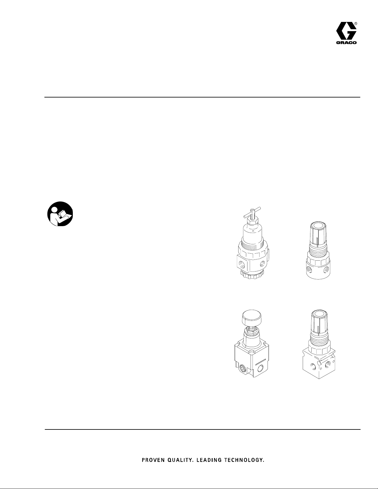
Low Volume Air Regulators
308167L
Used to ensure consistent air pressure in systems requiring up to a
maximum of 90 scfm.
300 psi (2.1 bar) Maximum Incoming Air Pressure
D Diaphragm- and Piston-Operated
D Self-Relieving
D Temperature Range: 40-120_F
Important Safety Instructions
Read all warnings and instructions in this manual.
Save these instructions.
See page 2 for a list of regulators. Bare regulators
are available separately or in the regulator assemblies shown with them.
See manual 308168 for higher volume regulators.
ENG
Table of Contents
List of Regulators 2. . . . . . . . . . . . . . . . .
Dimensions 3. . . . . . . . . . . . . . . . . . . . . .
Installation 4. . . . . . . . . . . . . . . . . . . . . . .
Adjustment 5. . . . . . . . . . . . . . . . . . . . . .
Repair 6. . . . . . . . . . . . . . . . . . . . . . . . . .
Repair Kit Drawings 7. . . . . . . . . . . . . .
Parts 8. . . . . . . . . . . . . . . . . . . . . . . . . . .
Accessories 10. . . . . . . . . . . . . . . . . . . .
Flow Curves 11. . . . . . . . . . . . . . . . . . . .
Graco Standard Warranty 12. . . . . . . .
Graco Phone Numbers 12. . . . . . . . . . .
104266, 104267,
171937, 110234,
113406
16G409
104815
110318
110341, 111804,
116903, 116904
Page 2

List of Regulators
BARE
Part No.
REGULATOR
REGULATOR
104815 15
110318
110147
110341 39
111804 39
110234
109075
224512
224024
104266
206849
203716
202156
202858
244844
248829
104267
206237
171937 90
Part No.
ASSEMBLY
(0.4)
15
(0.4)
(1.1)
(1.1)
90
(2.5)
90
(2.5)
90
(2.5)
(2.5)
(npt)
Max. SCFM
(m3/min)
Pressure Cup,
Prince
Mini–Flo, Standard &
Fast-Ball
Husky 715, Prince
Husky 1030
Husky 715, Prince
Husky 1030,
2.5 gal. Pressure Tank
PRO/Delta Spray Packages
Standard,
Monark
President
Monark, President
Lube Ranger
Monark, President,
Husky 1030, Glutton
Pressure Tanks 1/2 1/4 Te e 0–125 psi
Application
Pump/System
r, Fireballr,
r
Inlet/Outlet Port
1/8 1/8 Knob 0–60 psi
1/4 1/8 Knob 0–180 psi
1/8 1/8 Knob 0–125 psi
1/4 1/8 Knob 0–125 psi
3/8 1/4 Te e 0–250 psi
1/2 1/4 Te e 0–250 psi
1/2 1/4 Te e 0–125 psi
(npt)
Gage Ports (2)
Handle Type
Regulated
Pressure RangeDiaphragm
(0–4.2 bar,
0–0.42 MPa)
(0–11 bar,
0–1.1 MPa)
(0–9 bar,
0–0.9 MPa)
(0–9 bar,
0–0.9 MPa)
(0–17.5 bar,
0–1.75 MPa)
(0–17.5 bar,
0–1.75 MPa)
(0–9 bar,
0–0.9 MPa)
(0–9 bar,
0–0.9 MPa)
Nitrile Rubber
Nitrile Rubber
None–piston type
None–piston type
Nitrile Rubber
Nitrile Rubber
Nitrile Rubber
PET
Material
113406 90
116903 39
116904 39
16G409 141
2 308167
(2.5)
(1.1)
(1.1)
(4)
Pressure Tanks 1/4 1/4 Te e 0–125 psi
(0–9 bar,
0–0.9 MPa)
Pressure Cup 1/8 1/8 Knob 0–60 psi
(0–4.2 bar,
(0–0.4 MPa)
Pressure Cup 1/8 1/8 Knob 0–25 psi
(0–1.8 bar)
(0–0.2 MPa)
Fluid Pressure Regulator 1/4 1/8 Knob 0–58 psi
(0– 3.9 bar)
(0– 0.3 MPa)
Nitrile Rubber
None–piston type
None–piston type
Nitrile Rubber
Page 3
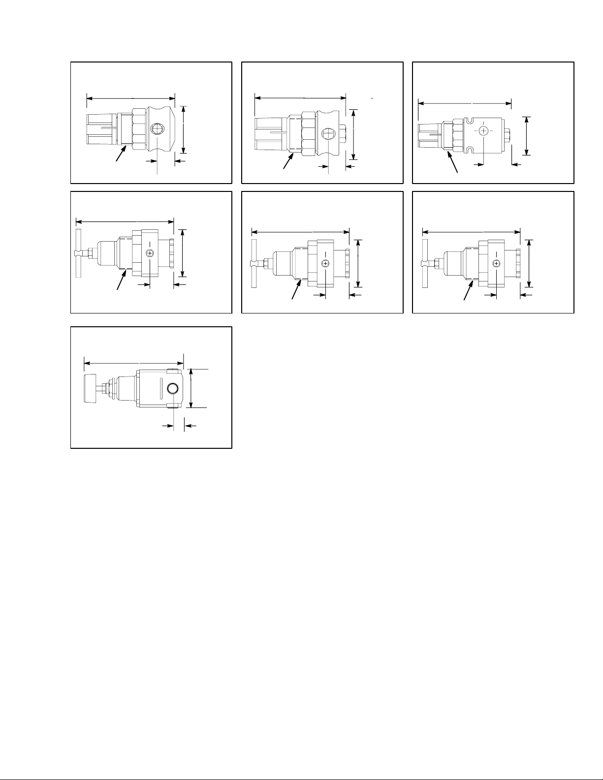
Dimensions
Model 104815 (1/8 in. Port)
3 in. (80 mm)
1-13/16–18
Model 110234 (3/8 in. Port)
6.0 in. (152 mm)
1-3/4–18
Model 16G409 (1/4 in. Port)
1.5 in.
(38 mm)
0.5625 in.
(14 mm)
2.31 in.
(59 mm)
1.38 in.
(35 mm)
Model 110318 (1/4 in. Port)
3.1 in. (88 mm)
1.56 in.
(40 mm)
1-13/16–18
0.5 in.
(13 mm)
Model 104266, 104267 (1/2 in. Port)
113406 (1/4 in. Port)
6.0 in. (152 mm)
2.31 in.
(59 mm)
1-3/4–18
1.38 in.
(35 mm)
Model 110341 (1/8 in. Port)
Model 111804 (1/4 in. Port)
Model 116903, 116904 (1/8 in. Port)
4.1 in. (104 mm)
1.61 in.
(41 mm)
1.125 in.
1-13/16–18
(28.6 mm)
Model 171937 (1/2 in. Port)
6.0 in. (152 mm)
2.31 in.
(59 mm)
1.38 in.
1-3/4–18
(35 mm)
4.8 in. (123 mm)
1.96 in.
(50 mm)
0.71 in.
(18 mm)
3308167
Page 4

Installation
Before installing any air line components, blow out the
pipe line to remove scale and other debris. Use pipe
compound or tape sparingly and only on male threads.
Install the regulator in the pipe line so the flow is in the
direction of the arrow stamped on the body. Locate the
regulator as close as possible to the equipment it
serves.
Mounting brackets and nuts are available. See page
10.
WARNING
To reduce the risk of serious bodily injury, including
fluid injection, splashing fluid in the eyes or on the
skin, or injury from the pump starting unexpectedly,
be sure your system includes a bleed–type
master air valve.
Install the air valve between the air regulator outlet
and the device the regulator is serving. When
relieving system air pressure, close the bleed–type
master air valve to fully relieve air pressure.
To provide the user with a variety of assembly options,
a bleed–type master air valve is not included with all
regulator assemblies. See ACCESSORIES to order
this valve. Another bleed–type master air valve may
also be installed upstream from the air controls to
isolate them for servicing.
Be sure the air to the regulator is clean. Erratic regulator operation or loss of regulation is usually caused by
dirt in the disc area. To clean the regulator, see the
REPAIR section on page 6.
4 308167
Page 5

Adjustment
Relieving Pressure
1. Close the bleed–type master air valve to bleed air
between the valve to the device it is serving.
2. Trigger the gun or dispense valve and open any
fluid drain valves to relieve fluid pressure.
Adjusting Pressure with a
T-Handle Regulator
3. Loosen the locknut.
4. To increase the regulated air pressure, turn the
T-handle clockwise.
5. To decrease the regulated air pressure, turn the
T-handle counterclockwise.
6. Tighten the locknut to lock in the adjustment.
Adjusting Pressure with a Knob–type
Regulator
1. If the knob does not have a screw, pull the knob
up to adjust. When the adjustment is complete,
push the knob down to lock it in place.
2. If the knob has a cross–head screw, loosen the
screw 1/4 turn and the adjust the knob. Tighten the
screw to lock in the adjustment.
3. To increase the regulated air pressure, turn the
knob clockwise.
4. To decrease the regulated air pressure, turn the
knob counterclockwise.
Knob
Bleed–type master
air valve
(Shown open)
Locknut
5308167
Page 6

Repair
WARNING
Relieve air and fluid pressure before servicing the
regulator.
o reduce the risk of serious bodily injury, fluid
injection, splashing in the eyes or skin, injury from
moving parts, ALWAYS open the bleed–type master air valve (required) to relieve system air pressure and trigger the gun or dispense valve and
open any fluid drain valves to relieve fluid pressure.
Wash the parts with household soap and water or
denatured alcohol. Wipe the parts dry with a clean,
soft, dry rag. Use compressed air to blow dirt and
contaminants out of the regulator body.
CAUTION
Do not use trichloroethylene, acetone or similar
solvents to clean the regulator. These solvents could
damage the regulator parts.
Inspect all parts for wear or damage. Replace damaged parts.
If the regulator fails to operate, operates roughly,
vibrates, etc., follow the WARNING above. Remove
the regulator and service it as follows.
Disassemble the regulator. See the drawings on page
7.
Lubricate the bearing area, adjusting screw threads,
and spring ends with No. 2 lithium-base grease. Reassemble the regulator.
When installing the diaphragm, be sure the disc is
firmly in place. Install the disc stem in the center hole
of the diaphragm. Torque the spring housing to
45 in–lb (51 N.m).
Repair Kit Chart
This chart identifies the available repair kits for the regulators covered in this manual. The cutaway drawings shown
on page 7 show the contents.
REPAIR KITS
BARE
Part No.
REGULATOR
104816
1/8” Knob
106173
T–Handle
180780
1/2” Diaphragm
180781
1/2” Diaphragm
180782
3/8” & 1/2”
Diaphragm
104817
1/8” Diaphragm
223164
1/8” & 1/4” Piston
104695
1/2” Cap
112351
Disc
6 308167
104266 X X X X
104267 X X X
171937 X X X
110234 X X
104815 X X
110341 X
111804 X
110318 X X
113406 X X X
116903 X
116904 X
Page 7

Repair Kit Drawings
FOR REGULATORS 104815, 110318
DIAPHRAGM
ADJUSTING KNOB
ADJUSTING SCREW
NUT
COMPRESSION
SPRING
SPRING
HOUSING
Torque to
45 in-lb
(51 N.m)
Knob Kit 104816
Diaphragm Kit
104817
FOR REGULATORS
104267, 171937,
104266, 110234,
113406
Valve Kits
for regulator 104267,
for regulator 171937
for regulators 104266,
180780
113406
180781
180782
110234
DISC
COMPRESSION
SPRING
SPRING
DIAPHRAGM
BODY
(not included)
O–RING
DISC
SPRING
T–HANDLE
LOCKNUT
SPRING GUIDE
SPRING HOUSING
Torque to
45 in–lb
(51 N.m)
DISC
O–RING
CAP
Torque to
45 in–lb (51 N.m)
Disc Kit 112351
for regulator 104266 only
T–Handle Kit
106173
Cap Kit 104695
0926
FOR REGULATORS
110341, 111804,
116903, 116904
PISTON
SEAT
O-RING
STEM & DISK
Piston
Kit
223164
7308167
Page 8

Parts
3/8 npt
INLET
3
1
3/8 npt
OUTLET
2
1/2 npsm
OUTLET
0761
Model 109075
Ref
No. Part No. Description Qty
1 110234 3/8” AIR REGULATOR 1
2 100721 PLUG, pipe, 1/4 npt 1
3 100960 GAUGE, 0–200 psi (0–14 bar) 1
2
1
3
4
3
1/4 npt
OUTLET
1/4 npt
INLET
1
2
Model 110147
Ref
No. Part No. Description Qty
1 110318 1/4” AIR REGULATOR 1
2 100403 PLUG, pipe, 1/8 npt 1
3 110319 GAUGE, 0–200 psi (0–14 bar) 1
3/8 npt
OUTLET
1/2 npsm
INLET
3
4
5
0762
3/8 npt
INLET
Model 224512
Ref
No. Part No. Description Qty
1 110234 3/8” AIR REGULATOR 1
2 100960 GAUGE, 0–200 psi (0–14 bar) 1
3 110224 BALL VALVE, 3/8–18 npt(f) 1
4 156849 NIPPLE, 3/8–18 npt 1
1/4 npt
INLET
0944
2
3
3/8 npt
OUTLET
1
5
4
Model 224024
Ref
No. Part No. Description Qty
6
7
8
Model 206237
Ref
No. Part No. Description Qty
1 104267 1/2” AIR REGULATOR 1
2 100721 PLUG, pipe, 1/4 npt 1
3 101180 GAUGE, 0–200 psi (0–14 bar) 1
4 208393 BALL VALVE, 3/8–18 npt 1
5 158256 UNION, swivel, 1
6 162376 MANIFOLD, 1/2 npt(f) swivel, x
1/2 npt(m), two 1/8–27 npt ports 1
7 100403 PLUG, 1/8–27 npt 2
8 151519 NIPPLE, 1/4–18 x 1/8–27 npt 1
9 208625 AIR BLOW GUN 1
1
2
9
0943
1 110234 3/8” AIR REGULATOR 1
2 100960 GAUGE, 0–200 psi (0–14 bar) 1
3 156849 NIPPLE, 3/8–18 npt 1
4 169970 FITTING, air line, 1/4 npt(m) 1
5 208536 COUPLER, air line 1
8 308167
Page 9

Parts
1/4 npt
INLET
3
47
3/8 npt
OUTLET
1
6
5
Model 206849
Ref
No. Part No. Description Qty
1 104266 1/2” AIR REGULATOR 1
2 100721 PLUG, pipe, 1/4 npt 1
3 100960 GAUGE, 0–200 psi (0–14 bar) 1
4 159239 NIPPLE, pipe, 1/2 x 3/8 npt 1
5 166999 ELBOW, 1/2 (m) x 1/4 (f) npt 1
6 169970 FITTING, air line, 1/4 npt(m) 1
7 208536 COUPLER, air line 1
2
0758
5
1/2 npsm
INLET
3
1
3
4
3/8 npt
INLET
1
4
3/8 npt
OUTLET
Model 202156
Ref
No. Part No. Description Qty
1 104266 1/2” AIR REGULATOR 1
2 100721 PLUG, pipe, 1/4 npt 1
3 100960 GAUGE, 0–200 psi (0–14 bar) 1
4 100081 BUSHING, 1/2(m) x 3/8 (f) npt 1
2
0759
3
1/2 npsm
INLET
5
1
4
3/8 npt
OUTLET
1
1/2 npt
INLET
4
2
0760
_ swivel, 1/2 npt(m)
x 1/2 npsm(f) swivel 1
3
2
1/2 npt
OUTLET
ti1603b
3/8 npt
OUTLET
Model 203716
Ref
No. Part No. Description Qty
1 104266 1/2” AIR REGULATOR 1
2 100721 PLUG, pipe, 1/4 npt 1
3 101180 GAUGE, 0–200 psi (0–14 bar) 1
4 159239 NIPPLE, pipe, 1/2 x 3/8 npt 1
5 207438 UNION, 90
Model 244844
Ref
No. Part No. Description Qty
1 104266 1/2” AIR REGULATOR 1
2 100721 PLUG, pipe, 1/4 npt 1
3 100960 GAUGE, 0–200 psi (0–14 bar) 1
Model 202858
Ref
No. Part No. Description Qty
1 104266 1/2” AIR REGULATOR 1
2 100721 PLUG, pipe, 1/4 npt 1
3 100960 GAUGE, 0–200 psi (0–14 bar) 1
4 159239 NIPPLE, pipe, 1/2 x 3/8 npt 1
5 156684 UNION, swivel, 1/2 npt(m) x
1/2 npsm(f) swivel 1
to feed
pump
2
5
0757
2
4
1
7
3
8
Model 248829
Ref
No. Part No. Description Qty
1 104266 1/2” AIR REGULATOR 1
2 113333 VALVE, ball vented, 3/8 npt 1
3 101689 GAUGE, 0–200 psi (0–14 bar) 1
4 156849 NIPPLE, pipe, 3/8 npt 1
5 155494 UNION, swivel, 3/8 npt(m) x
6 169970 FITTING, line air, 1/4 npt 1
7 100081 BUSHING, pipe, 1/2 x 3/8 npt 1
8 100206 BUSHING, pipe, 1/2 x 1/4 npt 1
6
3/8 npsm(f) 1
connect to
coupler from
Kit 248827
TI5686
9308167
Page 10

Accessories
GAUGES
Gauge
Part
Number
160430 0–100 (7) 1/4 Black 2 (51) 1 102019
100960 0–200 (14) 1/4 Black 2 (51) 1 102019
101180 0–200 (14) 1/4 Chrome 2 (51) 1 102019
104655 0–60 (4) 1/8 Black 1.5 (38) 1 N/A
101689 0–200 (14) 1/4 Chrome 2 (51) 2 102019
108190 0–100 (7) 1/8 Black 1.5 (38) 2 N/A
110319 0–200 (14) 1/8 Black 1.5 (38) 1 N/A
Regulator Mounting
Bracket & Nut 105252
For Regulators
104266
104267
113406
Air
Pressure
Range
psi (bar)
171937
110234
111804
1-3/4–18
thread
1.77” dia.
Inlet
npt(m)
Type of
Case
(includes
ring)
Panel Mounting
Bracket & Nut 110321
For Regulators
104815
110341
110318
111804
1-13/16
thread
1.25” dia.
Dial
Dia.
inch (mm)
Style Glass
P/N
Panel Mounting
Nut 110209
For Regulators
104815
110341
1-13/16 thread
110318
111804
1.25” dia.
Style 1 (Bottom Inlet)
Style 2 (Back Inlet)
BLEED-TYPE MASTER AIR VALVES
Part No. Description
107141 3/4 npt (m x f)
107142 1/2 npt (m x f)
110223 1/4–18 npt (fbe)
110224 3/8–18 npt (fbe)
110225 1/2–14 npt (fbe)
110226 3/4–14 npt (fbe)
10 308167
Page 11

Flow Curves
Model 104266, 104267, 171937 (1/2 in. Port)
Model 110234 (3/8 in. Port)
Model 113406 (1/4 in. Port)
80
60
40
20
0
Reduced Pressure (PSIG)
0 102030405060708090100
100 PSIG Supply
Air Flow (SCFM)
Model 104815 (1/8 in. Port)
Model 110318 (1/4 in. Port)
80
100 PSIG Supply
For Model
60
40
110318 only
Model 110341 (1/8 in. Port)
Model 111804 (1/4 in. Port)
Model 116903, 116904 (1/8 in. Port)
80
60
40
20
0
Reduced Pressure (PSIG)
0 5 10 15 20 25 30 35 40
100 PSIG Supply
Air Flow (SCFM)
20
0
Reduced Pressure (PSIG)
0 2 4 6 8 10 12 14 16
Air Flow (SCFM)
11308167
Page 12

Graco Standard Warranty
Graco warrants all equipment manufactured by Graco and bearing its name to be free from defects in material and workmanship on the
date of sale to the original purchaser for use. With the exception of any special, extended, or limited warranty published by Graco,
Graco will, for a period of twelve months from the date of sale, repair or replace any part of the equipment determined by Graco to be
defective. This warranty applies only when the equipment is installed, operated and maintained in accordance with Graco’s written
recommendations.
This warranty does not cover, and Graco shall not be liable for general wear and tear, or any malfunction, damage or wear caused by
faulty installation, misapplication, abrasion, corrosion, inadequate or improper maintenance, negligence, accident, tampering, or substitution of non–Graco component parts. Nor shall Graco be liable for malfunction, damage or wear caused by the incompatibility of
Graco equipment with structures, accessories, equipment or materials not supplied by Graco, or the improper design, manufacture,
installation, operation or maintenance of structures, accessories, equipment or materials not supplied by Graco.
This warranty is conditioned upon the prepaid return of the equipment claimed to be defective to an authorized Graco distributor for
verification of the claimed defect. If the claimed defect is verified, Graco will repair or replace free of charge any defective parts. The
equipment will be returned to the original purchaser transportation prepaid. If inspection of the equipment does not disclose any defect
in material or workmanship, repairs will be made at a reasonable charge, which charges may include the costs of parts, labor, and
transportation.
THIS WARRANTY IS EXCLUSIVE, AND IS IN LIEU OF ANY OTHER WARRANTIES, EXPRESS OR IMPLIED, INCLUDING BUT
NOT LIMITED TO WARRANTY OF MERCHANTABILITY OR WARRANTY OF FITNESS FOR A PARTICULAR PURPOSE.
Graco’s sole obligation and buyer’s sole remedy for any breach of warranty shall be as set forth above. The buyer agrees that no other
remedy (including, but not limited to, incidental or consequential damages for lost profits, lost sales, injury to person or property, or any
other incidental or consequential loss) shall be available. Any action for breach of warranty must be brought within two (2) years of the
date of sale.
Graco makes no warranty, and disclaims all implied warranties of merchantability and fitness for a particular purpose in connection
with accessories, equipment, materials or components sold but not manufactured by Graco. These items sold, but not manufactured
by Graco (such as electric motors, switches, hose, etc.), are subject to the warranty, if any, of their manufacturer. Graco will provide
purchaser with reasonable assistance in making any claim for breach of these warranties.
In no event will Graco be liable for indirect, incidental, special or consequential damages resulting from Graco supplying equipment
hereunder, or the furnishing, performance, or use of any products or other goods sold hereto, whether due to a breach of contract,
breach of warranty, the negligence of Graco, or otherwise.
FOR GRACO CANADA CUSTOMERS
The parties acknowledge that they have required that the present document, as well as all documents, notices and legal proceedings
entered into, given or instituted pursuant hereto or relating directly or indirectly hereto, be drawn up in English. Les parties reconnaissent avoir convenu que la rédaction du présente document sera en Anglais, ainsi que tous documents, avis et procédures judiciaires
exécutés, donnés ou intentés à la suite de ou en rapport, directement ou indirectement, avec les procedures concernées.
Graco Information
For the latest information about Graco products, visit www.graco.com.
TO PLACE AN ORDER, contact your Graco distributor or call to identify the distributor closest to you:
Phone: 612–623–6921 or Toll Free: 1–800–328–0211 Fax: 612–378–3505
All written and visual data contained in this document reflects the latest product information available at the time of publication.
Graco reserves the right to make changes at any time without notice.
12 308167
Original instructions. This manual contains English. MM 308167
Graco Headquarters: Minneapolis
International Offices: Belgium, China, Japan, Korea
GRACO INC. P.O. BOX 1441 MINNEAPOLIS, MN 55440–1441
Copyright 1995, Graco Inc. is registered to ISO 9001
www.graco.com
Revised 10/2010
 Loading...