

Page 1
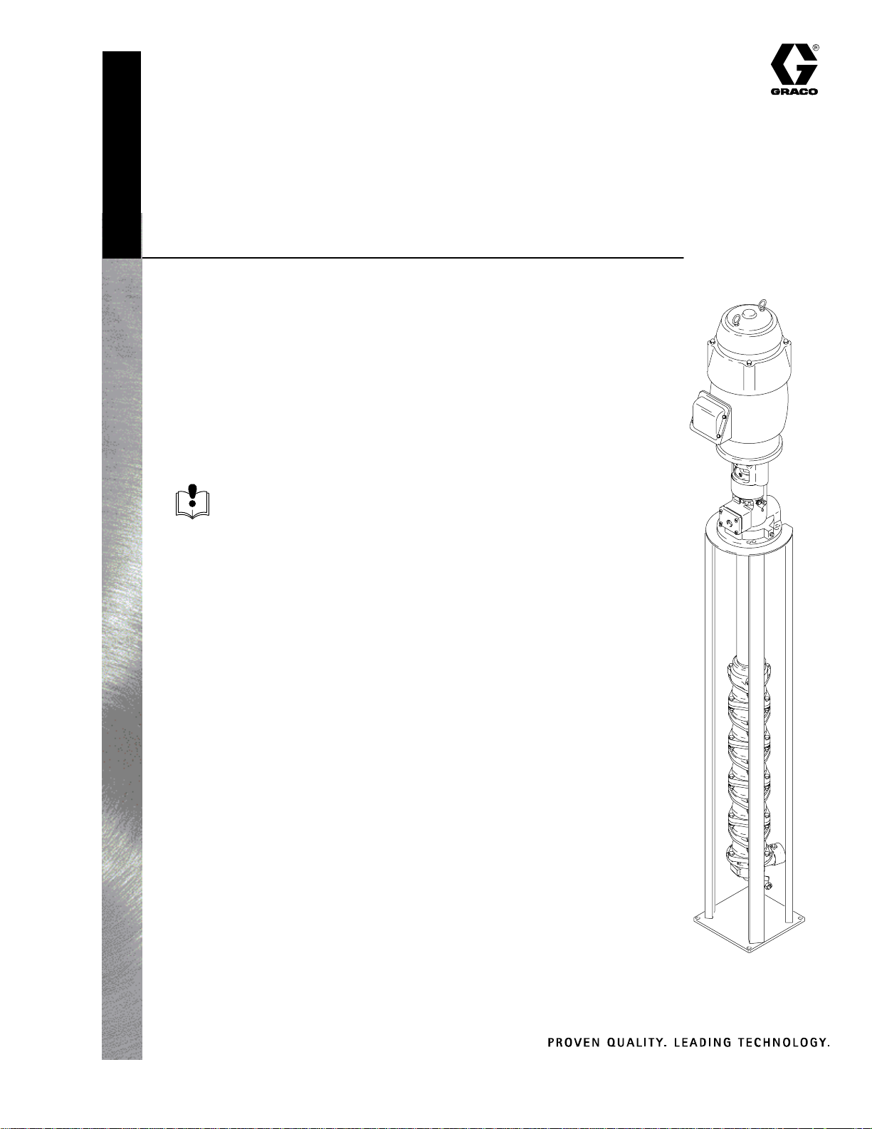
Instructions – Parts List
Parts
FREE-STANDING; CORROSION-RESISTANT OR WATERBORNE
Crown Imperial Pumps
250 psi (1.7 MPa, 17 bar) Maximum Working Pressure
Electric, Multi-Stage, Centrifugal,
Open Stand-Mounted Pumps for Circulating Systems
Read warnings and instructions.
See page 2 for table of contents and list of
models.
308059L
GRACO INC.ąP.O. BOX 1441ąMINNEAPOLIS, MNą55440-1441
Copyright 2002, Graco Inc. is registered to I.S. EN ISO 9001
Motor and Stand
Not Included
with Pump
03118
Page 2
Models
CORROSION-RESISTANT WATERBORNE WATERBORNE HD
No.
of
Stag
es
10 223910 224010 224110 224210 249103
11 223911 224011 224111 224211 249104
12 223912 224012 224112 224212 249105
13 223913 224013 224113 224213 249106
14 223914 224014 224114 224214 249107
15 236615 236715 249108
Standard
Size for 60”
High Tanks
Model No. Model No. Model No. Model No. Model No.
6 223906 224006 224106 224206
7 223907 224007 224107 224207
8 223908 224008 224108 224208
9 223909 224009 224109 224209
High Profile
for 85” High
Tanks
Standard
Size for 60”
High Tanks
High Profile
for 85” High
Tanks
Standard Size for 60”
High Tanks
Pump mounting stands
Purchase separately.
218631 for Standard-size pump
220266 for High Profile-size pump
Table of Contents
Warnings 2. . . . . . . . . . . . . . . . . . . . . . . . . . . . . . . . . . . . . .
Installation 4. . . . . . . . . . . . . . . . . . . . . . . . . . . . . . . . . . . . .
Operation 7. . . . . . . . . . . . . . . . . . . . . . . . . . . . . . . . . . . . .
Lubrication 9. . . . . . . . . . . . . . . . . . . . . . . . . . . . . . . . . . . .
Preventive Maintenance 9. . . . . . . . . . . . . . . . . . . . . . . . .
Troubleshooting 10. . . . . . . . . . . . . . . . . . . . . . . . . . . . . . .
Service 12. . . . . . . . . . . . . . . . . . . . . . . . . . . . . . . . . . . . . .
Parts 20. . . . . . . . . . . . . . . . . . . . . . . . . . . . . . . . . . . . . . . .
Dimensions 30. . . . . . . . . . . . . . . . . . . . . . . . . . . . . . . . . . .
Accessories 32. . . . . . . . . . . . . . . . . . . . . . . . . . . . . . . . . .
Technical Data 34. . . . . . . . . . . . . . . . . . . . . . . . . . . . . . . .
Graco Standard Warranty 36. . . . . . . . . . . . . . . . . . . . . .
Graco Information 36. . . . . . . . . . . . . . . . . . . . . . . . . . . . .
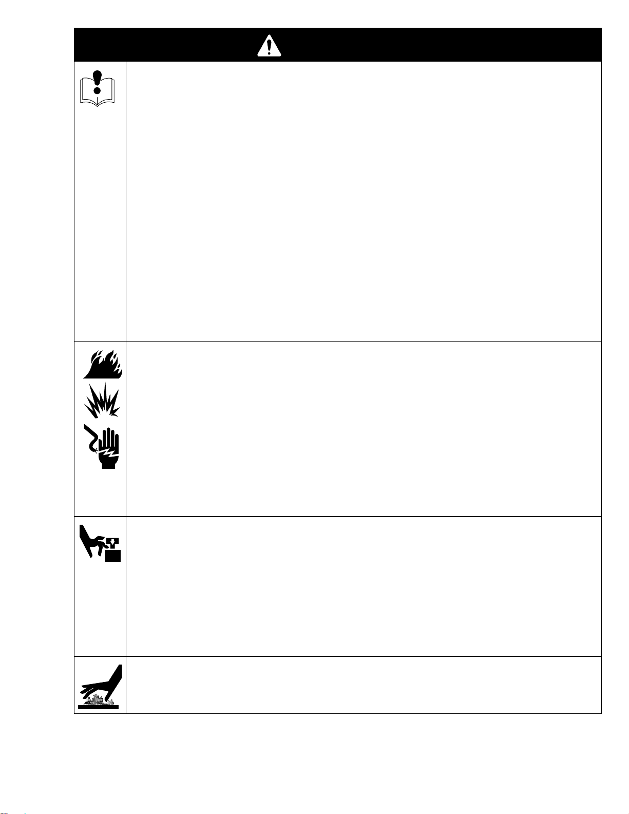
Symbols
Warning Symbol
WARNING
This symbol alerts you to the possibility of serious
injury or death if you do not follow the instructions.
Caution Symbol
CAUTION
This symbol alerts you to the possibility of damage to
or destruction of equipment if you do not follow the
corresponding instructions.
2 308059
Page 3
INSTRUCTIONS
WARNING
EQUIPMENT MISUSE HAZARD
Equipment misuse can cause the equipment to rupture or malfunction and result in serious injury.
This equipment is for professional use only.
Read all instruction manuals, tags, and labels before operating the equipment.
Use the equipment only for its intended purpose. If you are not sure, call your Graco distributor.
Do not alter or modify this equipment.
Check equipment daily. Repair or replace worn or damaged parts immediately.
Do not exceed the maximum working pressure of the lowest rated system component. Refer to the
Technical Data on page 34 for the maximum working pressure of this equipment.
Use fluids and solvents which are compatible with the equipment wetted parts. Refer to the Tech-
nical Data section of all equipment manuals. Read the fluid and solvent manufacturer’s warnings.
Wear hearing protection when operating this equipment.
Comply with all applicable local, state, and national fire, electrical, and safety regulations.
FIRE, EXPLOSION, AND ELECTRIC SHOCK HAZARD
Improper grounding, poor ventilation, open flames or sparks can cause a hazardous condition and
result in a fire or explosion and serious injury.
Ground the equipment. Refer to Grounding on page 5.
If there is any static sparking or you feel an electric shock while using this equipment, stop spray-
ing immediately. Do not use the equipment until you identify and correct the problem.
Provide fresh air ventilation to avoid the buildup of flammable fumes from solvents or the fluid
being sprayed.
Consult the electric motor manufacturer for the proper heater-breaker requirements.
MOVING PARTS HAZARD
Moving parts in the pump housing can pinch or amputate your fingers.
Keep clear of all moving parts when starting or operating the pump.
Keep all tools, etc. away from the moving parts to reduce the risk of accidentally catching and
breaking them.
Before servicing the equipment, shut off the electric power, relieve the pressure, and drain the
pump by opening the drain valve at the pump base.
HOT SURFACE HAZARD
The pump housing and pump shaft couplers become hot during operation. To reduce the risk of
burning yourself, do not touch them until they have cooled.
3308059
Page 4
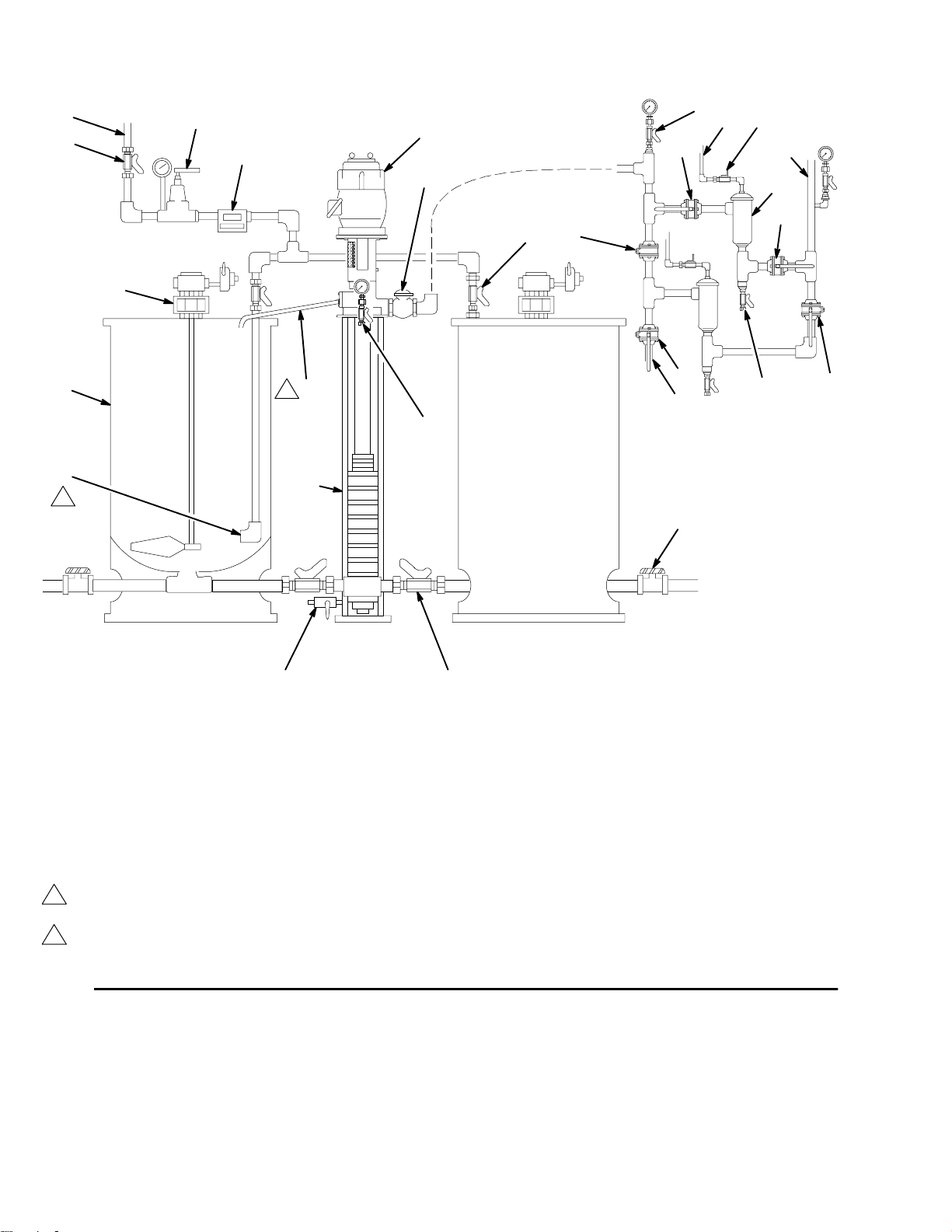
Installation
E
D
F
H
G
L
MN
Q
O
J
P
Q
KS
C
AA
B
Z
1
QR
T
U
A
2
V
X
YW
KEY
A Elbow
B Mix Tank
C Agitator
D Shutoff Valve, Return Line
E Return Line
F Back Pressure Valve
G Flow Meter
H Motor
1
Install drain tube at a maximum downward slope to the tank, with a minimum of 1/4 in. (6mm) per foot of tube.
To minimize turbulence, extend return line to bottom of tank
2
and use elbow to direct flow around perimeter of tank.
J Check Valve
K Tank Shutoff Valve
L Pressure Gauge with Pulsa-
tion Dampener and Isolation
Valve
M Open to Air
N Air Blowdown Valve
O To Spray Booth
P Fluid Filter
Q Line Isolation Valve
R Filter Drain Valve
S Standby Pump/System Blow-
down Connection Valve
T To Standby Pump
U Outlet Pressure Gauge with
Drain Valve
Fig. 1
03119
V Open Stand
W Outlet Shutoff Valve
X Tank Drain Valve
Y Pump Drain Valve
Z Drain Tube
AA Safety Isolation Valve
4 308059
Page 5
Installation
Grounding
WARNING
Ground the pump in accordance with all applicable
safety codes in your area. Proper grounding reduces the risk of shock, fire, or explosion caused
by static sparking, which can result in serious injury
and property damage.
1. Have a licensed electrician complete the electrical
hookup and wiring.
2. Consult the electric motor manufacturer for proper
heater-breaker requirements.
3. Before coupling the pump coupler to the motor
shaft coupler, check to be sure the shaft rotates in
the proper direction. Refer to Fig. 3, page 6.
System Design
The Typical Installation shown on page 4, and the
following text, is only a guide to show the relationship
of the pump to other system components. Due to the
pressure characteristics of the pump, which vary
widely with viscosity and specific gravity, professional
systems design is essential. Contact Graco (see back
page) for further information.
Return Line
Install a back pressure valve (F) to maintain proper line
pressure to all outlets. Install a flow meter (G) to
visually check the fluid flow rate.
Extend the return line (E) going into the mix tank (B) to
the bottom of the tank and end it with an elbow (A).
The elbow directs fluid around the walls of the tank to
help minimize air entrainment in the fluid.
Supply Line
Install a line check valve (J) near the 2 in. npt(f) pump
outlet.
CAUTION
The line check valve (J) is required to prevent fluid
backflow into the pump in case of a power failure or
incorrect operating procedure.
Install a pressure gauge (G) at the plugged 1/2 npt(f)
port at the left of the pump outlet. Make sure the
gauge is correctly rated for the operating pressure.
Fluid Filters
Install two fluid filters (P) with line isolation valves (Q)
on each side. This allows the system to be used while
cleaning a filter.
Pump dimensions and the mounting hole layout are
shown on page 30. The Technical Data is given on
page 32.
Fluid Lines
Line sizes depend on the flow requirements and calculated pressure drop due to the length of the run.
The pipe, tubing and fittings must be compatible with
the fluid and solvent you plan to use.
Keep in mind that sharp corners and fittings between
lengths of pipe or tubing may cause flow restrictions
and fluid breakdown. Use the longest lengths of pipe or
tubing available to minimize couplings. Use the most
direct route to the spray stations, and whenever practical, use long sweeping bends. A “holsclaw” bender is
recommended for making bends in tubing; a common
electrician’s or plumber’s bender is not satisfactory.
Remove burrs, dirt and contaminants from the ends of
the tubes before installing the fittings.
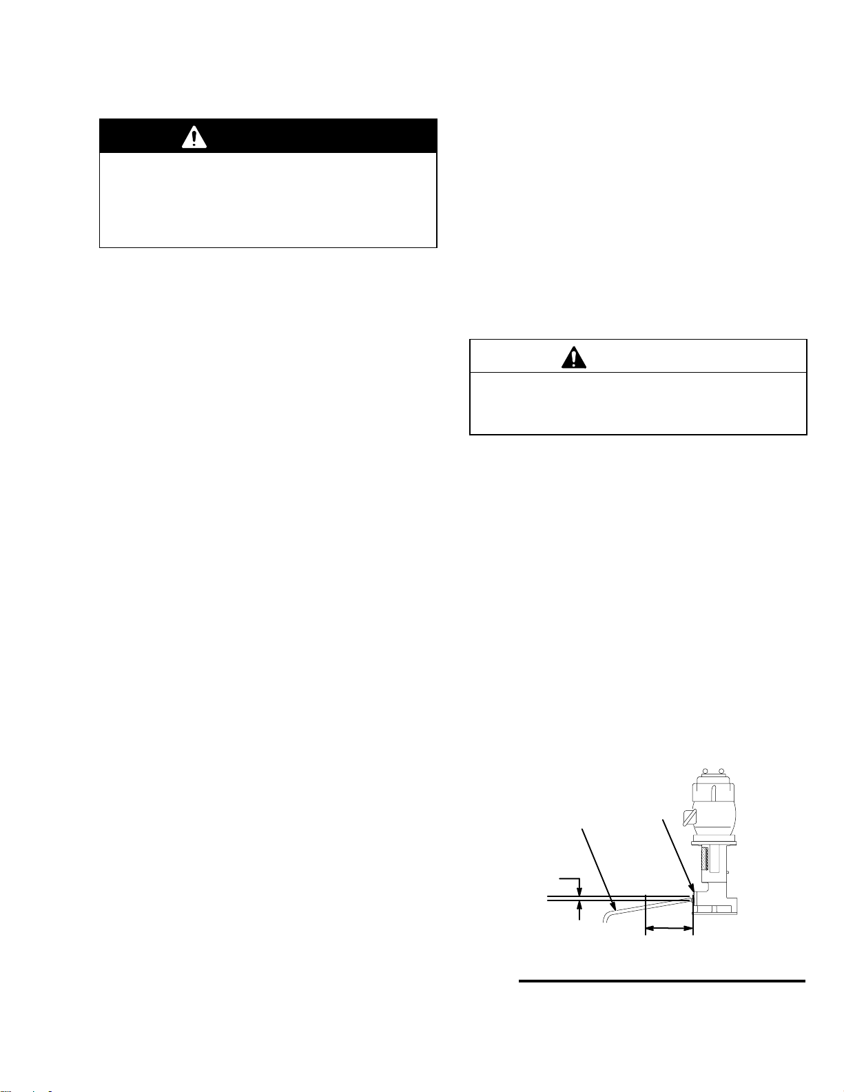
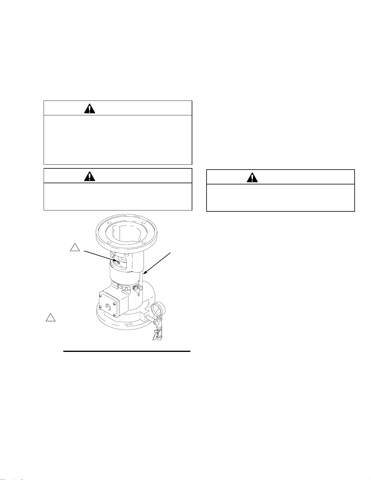
Overflow Tube
See Fig. 2. Remove the plug from the port of the
slinger cover (21). In the port; Install a minimum 3/4
in. (19 mm) ID drain tube (Z) for solvent based materials, and a minimum 1 in. (25 mm) ID drain tube for
waterborne materials. Slope the tube downward, a
minimum of .25 in. (6mm) per foot of tube and route
the tube into the mix tank.
Z
.25 in.
(6 mm)
Fig. 2
21
1 foot
(305 mm)
03120
5308059
Page 6
Installation
Mounting the Pump
Secure the pump, without the motor, in the pump
stand (V), using the bolts provided.
Be sure the pump inlet and the plumbing to the mix
tanks are at the same level. Install the necessary
plumbing, using shims as necessary. Then bolt the
pump standpipe and the tanks securely to the floor.
CAUTION
Do not flush the pump with any acid, caustic or
abrasive flush solution (line stripper) of any type. The
pump is designed to circulate automotive paint
coatings only.
After All Lines Are Installed
Flush all lines with a compatible solvent and blow out
with air. Then clean the elements of the filters (P).
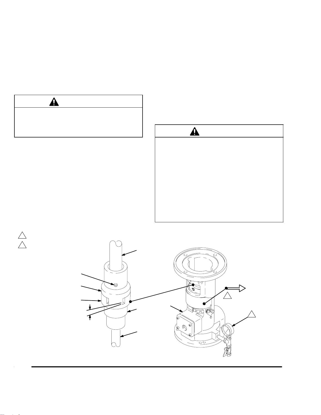
Installing the Motor
Remove the protective cover and the shipping dowel
from the pump base (31). Remove the motor coupler
(29).
When wiring the motor, be sure the shaft rotates in the
direction shown on the pump base and in Fig. 3.
Place the motor coupler (29) on the motor shaft (A),
pushing it up, well beyond the end of the shaft. Lightly
snug the setscrew (B).
Lower the motor onto the pump base, making sure the
motor locating flange seats properly on the pump
base.
Loosen the motor coupler setscrew (B). Pull the coupler (29) down to engage with the pump coupler (58)
and coupling insert (6).
Adjust the motor coupler to 0.094 in. (2.39 mm) clearance. See Fig. 3. Tighten the pump coupler setscrew.
CAUTION
1. Before operating the pump, turn the motor
coupler by hand to be sure the shaft rotates
freely in the correct direction. Then recheck the
0.094 in. (2.39 mm) coupler clearance.
2. The pump is factory-set to deliver maximum
outlet pressure. Do not tamper with this adjustment as it could cause damage to the impellers
and bowls and void the warranty.
3. Never leave any contaminants, nuts, bolts, rags,
etc., in the fluid tank or supply lines as they could
seriously damage the impellers or bowls.
1
2
Fig. 3
Outlet Pressure Gauge
Direction of Rotation for Motor
B
29
6
0.094 in. (2.39 mm)
A
58
33
2
31
1
0312203121
6 308059
Page 7
Operation
CAUTION
The pump is designed for continuous operation.
Regular shutdown at night or on weekends may
cause premature bearing wear and invalidate the
warranty.
Do not let the pump run dry. Operating the pump for
more than 10 seconds without fluid circulating
through it will overheat the pump and damage it.
2. Starting the pump
(Always use this procedure to start the pump)
a. Close the isolation valves (Q) on one filter.
b. Use the valve (Q) in front of the other filter to
control the pump flow to 50 psi (3.5 bar) until
the lines are full. Then completely open the
valve.
Flushing and Priming System
(See the Typical Installation and Fig. 3.)
The procedure given here is for a stand-mounted
pump, two mix tank system as shown in the Typical
Installation on page 4. Some specific instructions
may not apply to other systems; consult your plant’s
flushing procedures.
Flushing is important; it cleans all equipment and lines
of impurities. Following these instructions will help
assure satisfactory operation with quality control.
CAUTION
1. Be sure the motor rotates in the correct direction
and the drive coupler clearance is set at 0.094
in. (2.39 mm). See Fig. 3.
2. If the motor labors or the pump does not run
smoothly, check the motor for high amp draw
and check the thrust bearing for overheating.
The normal operating temperature is from 120
to 150 F (49 to 65 C). If the temperature is
higher than 150 F (65 C), consult a qualified
Graco representative after a repair check of the
drive coupler clearance.
c. Run the pump for several minutes, and then
shut off the pump.
d. Recheck the drive coupler for 0.094 in. (2.39
mm) clearance.
CAUTION
The pump coupler and bearing could move up during
shipment and then, when the pump is operated, it
could move down, leaving too much clearance. This
could damage both the coupler insert and the coupler.
3. Checking the system for leaks
a. Restart the pump and check the entire system
for leaks.
b. Tighten leaking joints as necessary.
c. Periodically check for leaks during flushing.
3. Be sure the circulating lines are flushed and
primed with fluid as instructed below. Do not
flush the pump with any acid, caustic or abrasive
flush solution (line stripper) of any type. The
pump is designed to circulate automotive paint
coatings only.
1. Preparing to flush the inside of the mix tanks
a. Close the outlet valves (W) of both tanks.
b. Pour about 100 gallons (380 liters) of the
appropriate solvent into each tank.
c. Open the outlet (W) and return valves (K) on
one tank only.
4. Continue flushing
a. Continue circulating the solvent, changing the
solvent as needed until the system is thoroughly flushed.
b. When the system is clean, stop the pump.
c. Drain all filtered residue from the filters (P).
d. Reconnect the return line (E) to the back
pressure valve (F).
7308059
Page 8
Operation
e. Close the outlet (W) and return valves (K) for
the tank being used and open the outlet and
return valves for the other tank.
f. Start the pump and circulate the solvent for at
least one hour.
g. While circulating, open the spray gun at each
drop and flush the hoses with about one gallon
(4 liters) of solvent.
5. When flushing is complete
a. Stop the pump and drain all solvent from the
tanks and lines.
b. Open the filter drain valves (R) to flush out all
filtered residue.
c. Thoroughly blow out the entire system with
clean, dry compressed air, or nitrogen, to
remove all solvent from the system.
6. Pumping paint
a. Fill a tank with paint and start the agitator (C).
b. Start the pump.
8. Flushing paint from system
Consult the paint supplier for a compatible solvent for
flushing paint from the system. Water reducible paints
should use de-ionized water and a solvent which will
keep resin in the solution. If water reducible paint has
a 20% solvent content, the flush media should also
contain approximately 20% solvent.
CAUTION
Do not flush the pump with any acid, caustic or
abrasive flush solution (line stripper) of any type. The
pump is designed to circulate automotive paint
coatings only.
CAUTION
De-ionized (D.I.) water is an aggressive, corrosive
material. It can be used on the waterborne versions
of the Imperial Pumps. Exposure of all other Imperial
Pumps to D.I. water should be minimized, and the
D.I. water should be flushed from the pump with a
non-corrosive material such as alcohol.
c. Use the filter isolation valve (Q) to control the
pump flow to 50 psi (3.5 bar) until the lines are
full, and then open the valve completely.
d. Circulate the paint until all air is removed from
the fluid lines.
e. While the paint is circulating, check and adjust
the viscosity as necessary.
7. Filling standby tank
a. Fill the other mix tank (standby tank) with paint
and start the agitator.
b. Leave the agitator running so that paint in the
standby tank will be ready for use when needed.
c. To keep air out of the system, always switch to
the standby tank before the paint supply in the
tank you have been using is completely
exhausted.
Adjusting System Pressure
Use the back pressure valve (F) to adjust the system
pressure.
Determine the line pressure required. Then, with paint
circulating in the line loop only, set the back pressure
valve so that the pressure at the last spray gun is 10
psi (0.7 bar) greater than needed.
Refer to the Typical Installation on page 4 and the
separate back pressure valve instructions.
CAUTION
The pump is set at the factory to deliver the maximum volume and outlet pressure. The pressure
cannot be increased by any adjustment of the pump.
Refer to Pump Thrust Bearing and Seal Replace-
ment, page 12, for proper adjustments.
8 308059
Page 9
Lubrication
Preventive
Lubricate the thrust bearing once a month if the pump
is operating continuously. To lubricate the bearing,
pump one or two shots (about 0.1 oz/2.8 grams) of
Chevron SRI/No. 2 NLGI grade grease through the
fitting on the top of the seal retainer. A 14 oz. tube of
this grease is supplied with the pump. See Fig. 4.
NOTE: Do not lubricate the bearing when you first
receive the pump as it is factory greased.
CAUTION
Use only Chevron SRI/No. 2 NLGI grade grease to
help prevent bearing overheating and premature
bearing failure. This green or brown-colored grease
is used for the factory pack and must not be mixed
with any other type of grease. The use of any other
type of grease will void the Graco Warranty.
CAUTION
Do not over grease the bearing, which may cause
the bearing to overheat. Remove any excess grease
after lubricating.
Maintenance
Thrust Bearing. Once a month, lubricate the thrust
bearing if pump is run continuously. Refer to thrust
bearing Lubrication instructions on this page. It is
recommended that the Imperial pump thrust bearing
assembly be replaced at least once a year.
Pump Pressure, Flow Rate, and Temperature. Once
a month, check the static discharge pressure, flow rate
of the pump, thrust bearing temperature, and coupler
clearance. Record them.
NOTE: If the operating temperature exceeds 150 F
(65 C) and normal maintenance, troubleshooting, and
service fails to reduce temperature, contact a qualified
Graco representative.
CAUTION
Blockage of the overflow tube and overflow chamber
on pump base will cause leakage through the shaft
seal and adjustment nut opening.
1
1
Grease here.
Fig. 4
Thrust Bearing Temperature Monitoring. The 3/8 in.
npt plug (54) can be removed from the pump base to
install a temperature sensor to monitor thrust bearing
temperatures. This sensor can be sourced by an
appropriate outside supplier.
54
03122
Overflow Tube. Once a month, check the overflow
tube and overflow chamber on pump base. Clean if
needed. Refer to Fig. 2 on page 5 for overflow tube
setup.
9308059
Page 10
Troubleshooting
CAUTION
When checking the pump pressure, do not leave the
check valve (J) or isolation valves (Q) closed for
more than 10 seconds while the pump is operating to
avoid overheating the pump and damaging the seals
and bearings.
NOTE: Graco offers a rebuild program on all Imperial
and Crown Imperial pumps. Contact your local sales
representative for details.
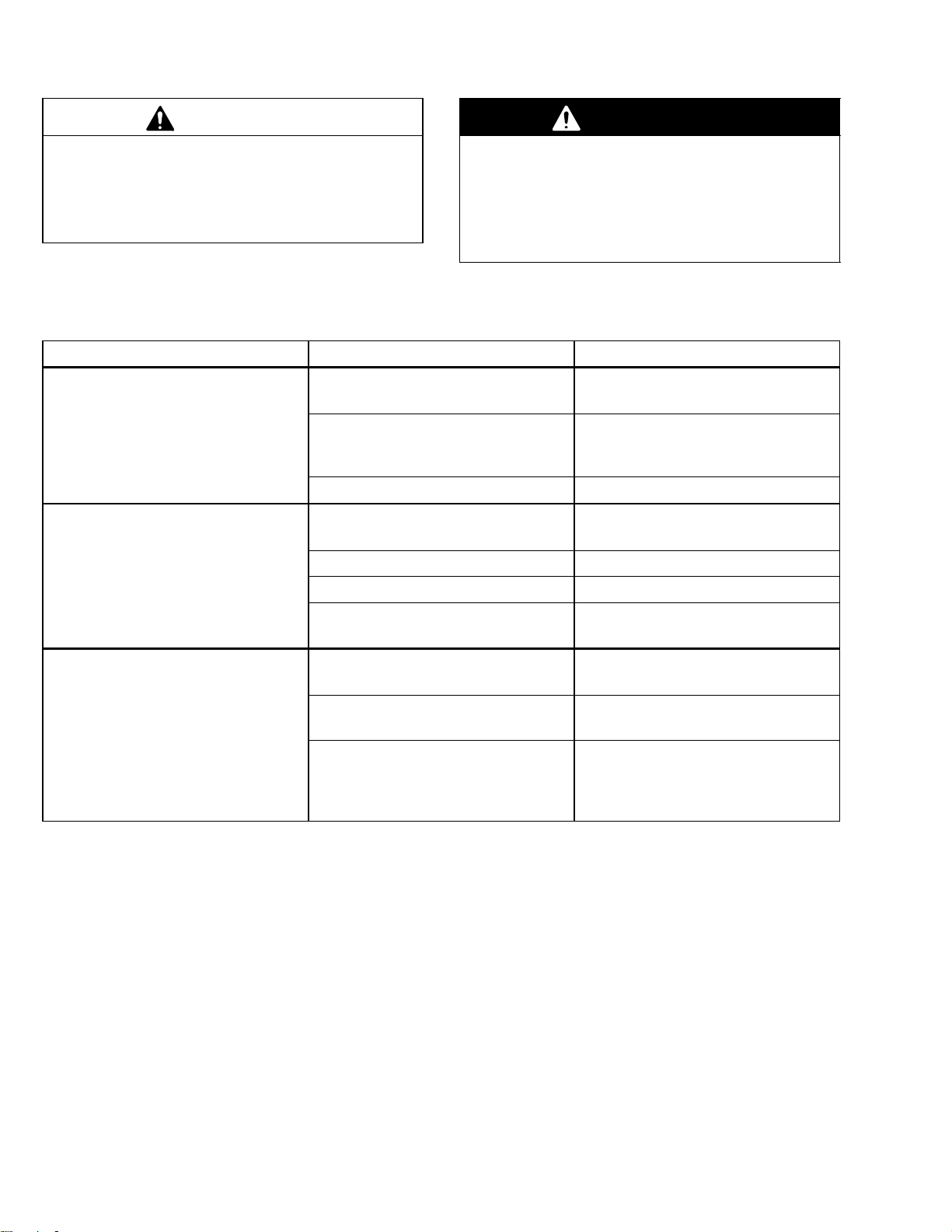
Problem Cause Solution
Pump won’t run. 1. Electric power out. 1. Check fuses; clean terminals
2. Fuses blown. 2. Check coupler clearance, re-
3. Motor inoperative. 3. Repair or replace motor.
Pump runs but pressure drops
slightly.
1. Clogged pump intake. 1. Remove and clean.
2. Increased flow rate. 2. Adjust back pressure valve.
3. Parts worn or damaged. 3. Repair pump.
4. Air entrained in fluid. 4. *Purge air. See Startup Proce-
Before removing the pump for repair, shut off the
electric power, relieve the pressure, and drain the
pump by opening the drain valve at the pump base.
This will help reduce the risk of serious injury from
electric shock, moving parts, or splashing fluid in
the eyes.
WARNING
and connections.
place fuses, repair pump (call
Graco Detroit, see back page).
dure on page 7.
Pump runs but pressure very low
or unsteady.
TROUBLESHOOTING CHART IS CONTINUED ON PAGE 11.
* Before removing the pump for cleaning, close the
check valve (J) or line isolation valves (Q) and note
the maximum pump pressure; the pressure should
be steady. Do not leave valves closed for more
than 10 seconds.
If pressure variations or pulsations are noted, the
problem could be 1.) a clogged intake, 2.) too low a
fluid level in the tanks, or 3.) restricted plumbing.
Correct the clogged condition to obtain steady
pressure.
1. Clogged pump inlet. 1. *Clean.
2. Air entrained in fluid. 2. *Purge air. See Startup Proce-
3. Problem with electric motor. 3. Check motor for proper rotation.
Low pressure can also be caused by air entrainment in
water reducible fluids. All return lines in tanks with
water reducible fluid must be routed to the bottom of
the tank.
Be careful to avoid allowing deteriorated pieces of bag
filters into the pump which can result in serious damage to the pump.
dure on page 7.
Check that RPM of motor is at
least 3750 under load.
10 308059
Page 11

Troubleshooting
Problem Cause Solution
Fluid leaking. 1. Screws or fittings loose. 1. Tighten.
2. Parts worn or damaged. 2. Repair pump.
3. Clogged bypass drain. 3. Drain.
Leakage at shaft seal (41).
(Leakage through the shaft seal/
adjustment nut opening.)
Noisy pump. 1. Improper coupler clearance. 1. Ensure 0.094 in. (2.39 mm)
Coupler insert (6) wears out prematurely.
1. Fluid viscosity is too light (especially if using solvent or other
flushing material).
2. Drain tube missing or not properly installed.
3. Drain tube blocked. 3. Clean drain tube.
2. Motor not seating properly to
pump housing.
3. Lack of grease in main thrust
bearing.
Motor not seating properly to
pump housing.
1. Seal is designed for heavier viscosity fluid, such as paint. Problem should clear up after flushing is completed.
2. Check size and slope of drain
tube; 3/4” ID and minimum
slope of 1/4” for each foot of
tube. See page 5.
clearance. See Fig. 3, page 6.
2. Loosen motor mount nuts, clean
flange and rotate motor to seat
properly; check seal for damage.
3. See Lubrication on page 9;
check for worn shaft bearings.
Loosen motor mount nuts, clean
flange and rotate motor to seat
properly; check seal for damage.
11308059
Page 12

Service
CAUTION
To avoid costly damage to the pump, follow this
service procedure carefully. Do not attempt to repair
anything that is not mentioned in this service section.
Before you start
Special tools needed for repairing the pump are mentioned in the text and described in the Accessories
section on page 32. Be sure you have all the necessary tools and repair parts on hand.
Shaft Holding
1
Tool 218634
(for standard pumps)
Shaft Holding
2
Tool 207727
(for high-profile
pumps)
36a
36b
1
2
Pump Thrust Bearing and Seal
Replacement
NOTE: It is not necessary to remove the pump from
the stand. However, if you are also repairing the lower
pump, you can install the shaft holding tool and move
the pump to the repair stand at this time. Use the tool
indicated in Fig. 5.
NOTE: Replace the pump thrust bearing (A) assembly
at least once a year. Replace the assembly if the pump
housing temperature goes over 150F (53C), which is
the first sign of bearing failure.
Disassembly
(Refer to Fig. 6, except where indicated)
1. Shut off the power to the pump. Close the check
valve (J) and/or the line isolation valves (Q). Open
the drain valve (Y) at the pump base, having a
container ready to catch the fluid. See page 4.
Remove the motor. Refer to Installing the Motor
on page 6.
2. Remove the slinger chamber screws, cover and
gasket (3, 21, 20). Inspect the chamber opening
and clean out any residue.
3. Remove the retainer plate (58c) and rubber coupling insert (6) from the pump coupling assembly
(58). Loosen the slinger (40) setscrew.
4. Hold the pump coupler (58) and screw the shaft
nut (28) off the shaft (33), using a socket wrench.
5. Remove the screws, washers and springs (10, 11,
25) and lift out the coupling assembly (58).
6. Remove the bearing support (22) and key (58b)
from the shaft (33).
03123
Fig. 5
8. Remove the three screws (13) and shaft seal
assembly (41).
NOTE: To service the lower pump section, refer to
page 15. Otherwise, continue with Step 9.
9. If the pump is mounted in a repair stand, install the
shaft holding tool. See Fig. 5.
10. Install the shaft seal assembly (41) with the three
screws (13).
11. Replace the shaft seal (8) in the adjusting nut (35).
Install the adjusting nut, engaging just one thread
in the pump base (31).
12. Position the bearing support (22) on the adjusting
nut (35) so its pin (P) and the slot in the support
align.
13. Screw the adjusting nut (35) down just until the
bearing support (22) bottoms out on the housing.
Turn the nut back 1 to 1-1/2 turns to engage
bearing support.
14. Slide the coupling assembly (58) over the shaft
(33).
15. Align the keyway and insert the key (58b) between
the coupling assembly and shaft.
16. Use the special tool, 178779, to check the shaft
location dimension. Place the tool on the face of
the coupler (58), between the coupler tabs as
shown in the detail of Fig. 7. The tabbed portion of
the tool should touch the top of the shaft (33).
Screw the adjusting nut (35) up until you attain the
0.25 in. (6.3 mm) dimension.
17. Install the shaft nut (28) using a socket wrench
and bottom it on the coupling assembly (58).
7. Remove the adjusting nut lockscrew and plug (19,
27). Then remove the adjusting nut (35).
12 308059
18. Align the hex of the nut retainer plate (58c) with
the shaft nut (28) and secure the lockwire (58d).
Page 13

58
58c
58d
58b
58a
48
29
Service
19. Install the two hold-down screws, washers, and
springs (10, 11, 25). Bottom the screws and check
the vertical travel of the retainer (A) against the
spring. If the shaft nut (28) and coupling housing
(58) are properly installed, the retainer should lift
5
6
10
11
25
28
A
0.12 to 0.19 in. (3.2 to 3.8 mm) before the springs
are solidly compressed.
20. If the pump is mounted in an assembly stand,
loosen the shaft holding tool. See Fig. 5.
Turn the bearing adjusting nut (35) two and a half
notches to the right to raise the impellers off the
bowls. Now turn the pump coupler (58) to be sure
the shaft (33) rotates freely. Check to see that the
slinger (40) is located approximately in the center
of the slinger chamber. See Fig. 7.
Fig. 6
41
31
3
22
8
P
35
13
41a
41e
41b
41c
41d
24
2
4
19
402021
27 26
If the pump is not mounted in an assembly
stand, turn the bearing adjusting nut (35) up until
the shaft (only) rotates freely. Then raise it another
two and a half notches to raise the impellers off the
bowls. See Fig. 7.
21. Install the lockscrew (19) through the pump base
and into the hole in the adjusting nut (35) without
forcing it. Install the plug (27). If necessary, turn
the adjusting nut a little, in the same direction as
pump rotation, until the plug goes in easily. Tighten
the plug securely and attach the lockwire (26) and
crimp. See Figs. 6 and 7.
22. Install the gasket, slinger chamber cover, and
screws (20, 21, 3) on the front of the pump base.
23. Install the rubber coupling insert (6) and remount
the motor. Refer to Fig. 3, page 6.
24. Remove the shaft holding tool, if installed. Install
the plug (49) and gasket (50) (see the parts
drawing). Start the pump. Use the filter isolation
valves (Q) to control the pump flow to 50 psi (3.5
bar) until the lines are full, and then completely
open the valves. Circulate the paint until all air is
removed from the fluid lines. Close the check valve
(J) or isolation valves (Q). Note the maximum
pump pressure. The pressure should be steady. If
variations or pulsations are noted, the inlet flow to
the pump is restricted, due to either a clogged
screen or restricted plumbing. Correct the clogged
condition.
CAUTION
03124
When checking the pump pressure, do not leave
the check valve (J) or isolation valves (Q) closed
for more than 10 seconds while the pump is operating to avoid overheating the pump and damaging
the seals and bearings.
13308059
Page 14

Tool 178779
58
33
Service
0.25 in. (6.3 mm)
03125
21
41a
28
58b
22
35
Notch
A
6
58
10
11
25
19
B
40
Fig. 7
14 308059
33
03126
Page 15

Service
25. Shut the pump off and recheck the coupler clearance; adjust if necessary to 0.094 in. (2.39 mm).
See Fig. 8.
26. Remove the seal chamber cover (21) and check to
be sure the slinger (40) is in the middle of the
chamber. See Fig. 7. If necessary, loosen the
setscrew (B) with a 0.19 in. hex key wrench to
readjust the slinger. Reinstall the cover, gasket and
screws (3, 20, 21).
31
29
58
0.094 in. (2.39 mm)
A
1
35
2
Repairing Shaft Bearings, Impellers,
and Seals
Disassembly
NOTE: Remove the pump from the regular stand.
1. Support the pump in a vertical position on the
accessory stand 953912, which must be bolted to
the floor for stability. Lock the pump in place. Refer
to Fig. 9.
2. Follow the disassembly procedure, Steps 1–8, on
page 12.
3. Remove the capscrews (14) at the top flange of
the riser tube (38). See Fig. 8.
NOTE: The two riser tubes used in the High Profile
pumps do not have to be disassembled.
4. Lift the pump base (31) straight up, off the shaft
(33). Avoid bending the shaft by unequal pulling
with a hoist or pry bars. Remove the capscrews
(14) at the bottom of the tube and remove the riser
tube (38). See Fig. 8.
Left –
1
Increase Pressure
Right –
2
Decrease Pressure
Torque to 30–35 ft–lb
3
(27–47 N.m)
Fig. 8
33
38
17
14
14
32
Assembly Stand
953912
3
3
03127
03128
Fig. 9
15308059
Page 16

Service
)
5. Disassemble the impeller bowls, working from the
top down.
a. Hold the first impeller with a spanner wrench
616637 and use a close fitting wrench to
loosen the impeller nut (32) 1–1 /2 turns. See
Fig. 9.
b. Place a 3/4 in. (19 mm) ID soft-steel, protect-
ing bushing, with a smooth turned end, on top
of the hex nut. Use a sharp downward blow
with a 1 foot (300 mm) length of pipe or tube
over the shaft (33) to loosen the collet (18).
See Fig. 10.
c. Remove the collet (18) and impeller (30). Do
not pry the impeller.
d. Remove all of the impeller bowl assemblies in
this way.
1 ft (300 mm)
Pipe
3/4 in. (19 mm)
ID Bushing
30
Fig. 10
37b
37a
32 18
37
33
03129
Pressing Tool
177219
0.06 in.
(1.6 mm
1
6. Inspect the shaft (33) for scoring or wear and
replace it, if needed. Check all bowls and impellers
for wear or damage and replace as needed. Install
new o-rings (9) on all impeller bowls (37b) and the
intake bowl (36a), then lubricate the o-rings in
place. Be sure the impeller nuts (32) rotate freely
on the collets.
7. To replace the bearings:
a. Use the short-nippled end of tool 177219 to
press out the bearings (37a) from all bowls
(37b) and the intake bowl (36a). See Fig. 11.
b. Use the long-nippled end of the tool to press
new bearings (36b, 37a) into the bowls. This
tool maintains the required 0.06 in. (1.6 mm)
dimensions of the impeller bowls as shown in
Fig. 11.
c. Thread the shaft holding tool into the bottom of
the intake bowl as shown in Fig. 12.
Procedure is continued on page 17.
9
Place long end down for
1
pressing new bearing
into impeller bowls.
03130
Fig. 11
Pressing Tool
177219
36a
36b
Shaft Holding Tool
1
207727 Shown
Installed (for
High Profile Pumps)
Use Shaft Holding Tool
2
218634 for Standard
Pumps
1
2
03131
Fig. 12
16 308059
Page 17

Service
d. Use the short-nippled end of tool 177219 to
press the new bearing into the intake bowl until
it bottoms against the shaft holding tool. Refer
to Fig. 11.
e. Check the bearings for concentricity. Place the
checking fixture 177218 on the bowl as shown
in Fig. 13. Drop the long end of the checking
tool 177217 into the center hole of the fixture.
The tool should turn freely without binding. If
the tool binds, the bearings must be replaced.
Reassembly
8. Slide the shaft (33) into the bearing in the intake
bowl (36a) and lock it in place with the shaft holding tool. See Fig. 14.
9. Clamp the intake bowl in a vise.
10. Assemble the first impeller (30), collet (18) and
impeller nut (32) onto the shaft (33). See Fig. 15.
Push downward on the impeller and hold it with the
spanner wrench, 616637, while tightening the
impeller nut to 130–150 ft-lb (175 – 205 Nm).
Refer to Fig. 16.
Shaft Holding Tool
1
207727 Shown
Installed (for
High Profile Pumps)
Use Shaft Holding Tool
2
218634 for Standard
Pumps
Fig. 14
33
36
1
2
03133
11. Install the first impeller bowl (37) and bolt it to the
intake bowl (36a) with screws (14) and lockwashers (17) and nuts (15). See Fig. 15.
NOTE: Each impeller must be bolted down tightly into
the bowl while tightening the impeller. This assures
contact with the machined face of the bowl, which will
ensure maximum pump performance.
Checking Fixture
177218
Checking
Tool
177217
37a
37b
03132
Fig. 13
37b
30
Torque to 130–150 ft–lb
1
(175–205 N.m)
Fig. 15
32
18
36a
1
14
17
15
03134
17308059
Page 18

Service
12. Remove the assembly from the vise and mount it
in the assembly stand 953912. See Fig. 16.
13. Continue assembling the bowls and impellers as in
Steps 10 and 11.
14. Install the riser tube (38) with the screws (14),
lockwashers (17) and nuts (15). See Fig. 8.
15. To replace the bearing (39) in the pump base (31),
remove the three screws and washers (7, 34),
holding the bearing from below. Press the bearing
out, using a 1.5 in. (38 mm) disc laid on the bearing and a 0.68 in. (17.3 mm) rod inserted from the
top to push it out. See Fig. 17. This bearing has a
medium-tight fit. Replace the bearing when replacing the impeller bearings.
Assembling Lower Pump Section to Base
NOTE: Be sure the pump base (31) is clean, and that
a new base bearing (39) has been installed.
1. Install the slinger (40) in the pump base with the
flange down. Use a wooden dowel, just under 0.75
in. (19 mm) diameter, to align the slinger when
assembling the pump base onto the shaft.
Torque to 130–150 ft–lb
1
(175–205 N.m)
32
1
Fig. 16
31
0.68 in.
(17.3 mm)
Rod
Spanner Wrench
616637
Assembly Stand
953912
03135
1.5 in.
(38 mm)
Flat Disc
2. Carefully lower the base (31) over the shaft (33),
passing the shaft through the bearing and slinger.
Seat the base firmly on the riser tube (38). Install
the four capscrews (14) and washers (17). Torque
to 30–35 ft-lb (27–47 Nm). Refer to Fig. 8.
3. Adjust the slinger to the center of the seal chamber opening. Tighten the slinger setscrew (B).
Refer to Fig. 7.
4. Continue assembling the pump as described in
Steps 10 to 26 on pages 12 to 15.
18 308059
34
7
39
03136
Fig. 17
Page 19

Notes
19308059
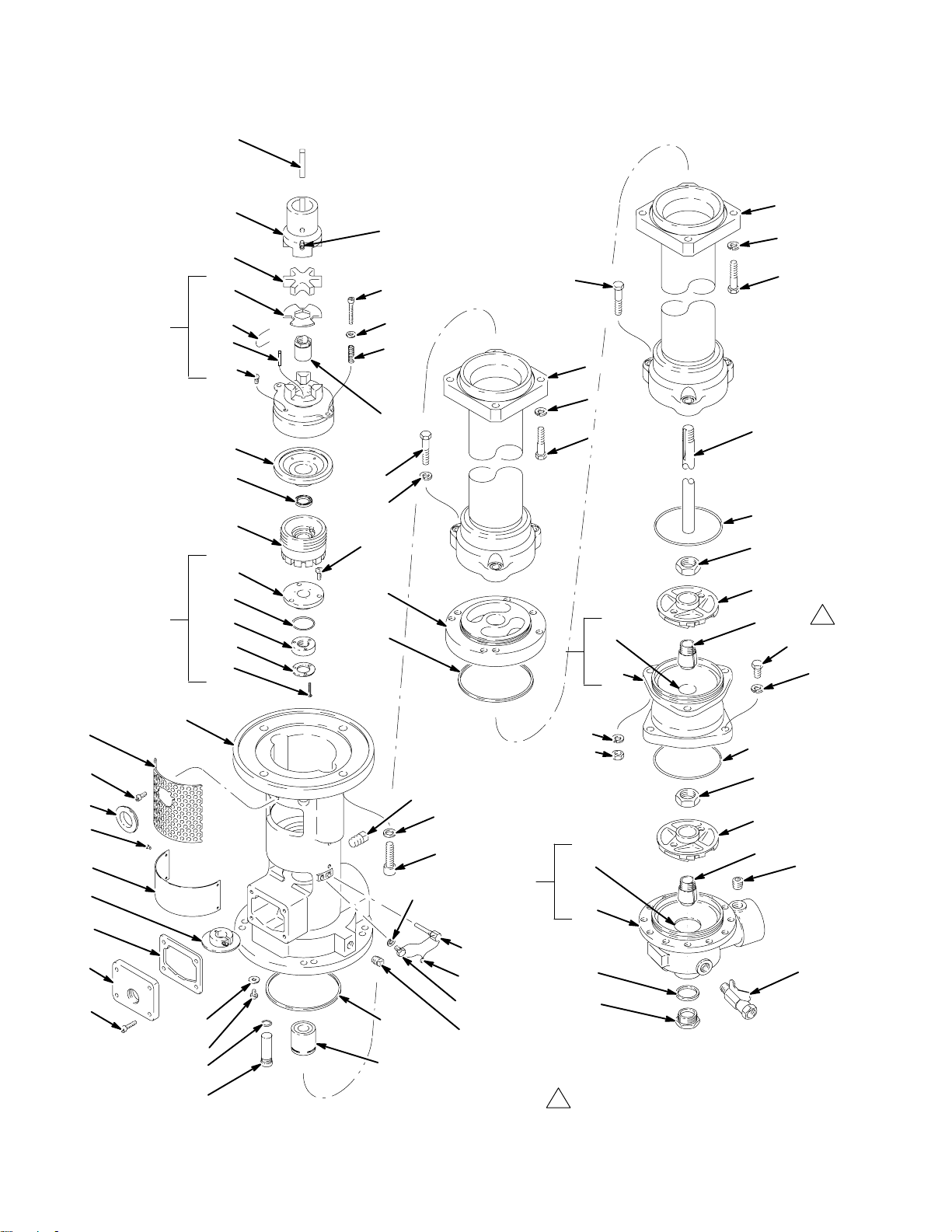
Page 20

Corrosion-Resistant, 60” Pump
48
Parts
58
41
29
58c
58d
58b
58a
22
35
41a
41e
41b
41c
38
5
6
10
11
25
28
8
13
37
14
37a
17
14
33
9
32
30
18
14 or 53
1
57
52
56
23
40
20
21
41d
31
54
1
3
34
7
63
62
12
39
24
2
4
36
19
26
27
16
37b
17
15
36b
36a
49
Use item 53 for last bowl
1
to intake only.
17
9
32
30
18
64
5150
03137
20 308059
Page 21

Parts
Corrosion-Resistant, 60” Pumps
Model Stages
223906 6
223907 7
223908 8
223909 9
223910 10
223911 11
223912 12
223913 13
223914 14
Ref
No. Part No. Description Qty
1 100055 SCREW, type “u” self tap, no. 6 x 1/4” 4
2 110343 CAPSCREW, sochd, 1/2–13 x 1–3/4” 4
3 110787 CAPSCREW, sch, 1/4–28 unf–3a x .75” 4
4 100214 LOCKWASHER,
5 100640 SCREW, cup pt slotted
headless set, 5/16 x 3/8” 1
6 102211* INSERT, coupling, rubber 1
7 110751 SCREW, mach, pnhd,
1/4–28 unf–2a x .375” 3
8 102776* SEAL,
shaft 1
9 106524* SEAL, o–ring, Viton
6 to 11 Stage Pumps 11
12 & 13 Stage Pumps 13
14 Stage Pumps 15
10 110753 CAPSCREW, sch,
1/4–28 unf–3a x 1.625” 2
11 110755 WASHER, plain, .281” ID 2
12 102848* PACKING, sq section 1
13 110752 SCREW, mach, pnhd,
1/4–28 unf–2a x .625” 3
14 103776 SCREW, hex hd, 7/16–14 x 2”
6 to 11 Stage Pumps 34
12 & 13 Stage Pumps 40
14 Stage Pumps 46
15 103777 NUT, hex, 7/16”
6 to 11 Stage Pumps 30
12 & 13 Stage Pumps 36
14 Stage Pumps 42
16 110786 PLUG,
pipe, 1/4–18 npt 1
17 103780 LOCKWASHER, spring 7/16”
6 to 11 Stage Pumps 37
12 & 13 Stage Pumps 43
14 Stage Pumps 49
18 186646* COLLET,
19 168352* SCREW, lock, adjusting nut 1
20 186117 GASKET, slinger 1
21 191401 COVER, slinger ring 1
22 168363 SUPPORT, bearing 1
23 186124 PLATE, instruction 1
24 168381 WASHER,
25 186111 SPRING, compression 2
26 104274 LOCK, wire 1
27 171711 PLUG, special 1
28 168500* NUT, shaft 1
spring, 5/16” 1
impeller 1/Stage
.53” ID 4
Ref
No. Part No. Description Qty
29 COUPLING,
motor,
170067 fits 1.38” (35 mm) motor shaft 1
169445 fits 1.12” (28.4 mm) motor shaft 1
30 170748* IMPELLER, pump 1/Stage
31 186096 BASE, pump 1
32 170770* NUT, impeller 1/Stage
33 176879 SHAFT,
impeller 1
34 170772 WASHER, plain, 1/4” 3
35 207769 NUT, adjusting 1
36 218097 INTAKE BOWL ASSEMBLY
Includes item 36a and 36b 1
36a 179909 .HOUSING, intake bowl 1
36b 176851 .BEARING,
intake bowl 1
37 218092 IMPELLER BOWL ASSEMBLY
Includes items 37a and 37b
6 to 11 Stage Pumps 10
12 & 13 Stage Pumps 12
14 Stage Pumps 14
37a 176851 .BEARING,
impeller bowl 1/bowl
37b 179774 .HOUSING, impeller bowl 1/bowl
38 TUBE, riser
218632 24.5” (622 mm)
6 to 11 Stage Pumps 1
220008 17.75” (451 mm)
12 & 13 Stage Pumps 1
220005 11” (280 mm)
14 Stage Pumps 1
39 218309 BEARING,
pump base 1
40 208846 RING, slinger 1
41 223605* SHAFT SEAL ASSEMBLY
Includes items 41a–41e 1
41a 186215 .SUPPORT, seal 1
41b 178697 .SEAL, shaft, PTFE 1
41c 170762 .RETAINER, seal 1
41d 107246 .SCREW, pan hd mach, no. 5–40 x 5/8” 3
41e 102895* .PACKING, o–ring, Viton 1
48 KEY,
parallel 1
107055 5/16”, use with coupling 170067 1
160906 1/4”, use with coupling 169445 1
49 178552 PLUG, 1–1/4 NF 1
50 178553 GASKET, plug, Delrin 1
51 237534 VALVE, ball, 3/8 npt (m x f) 1
52 110754 CAPSCREW,
sch, 1/4–28 unf–3a x .5” 1
53 110861 CAPSCREW, hex hd,
7/16–14 unc–2a x 1.5” 3
54 110762 PLUG, pipe, 3/8–18 npt 1
56 108027 GROMMET 1
57 186349 GUARD 1
58 223606 COUPLING ASSEMBLY
Includes replacement items 58a–58d 1
58a 100847 .FITTING, hydraulic, 1/4–28, 45 1
58b 168372 .KEY, 0.187” square x 1” long 1
58c 166007* .PLATE, retainer, shaft nut 1
58d 068069* .WIRE, lock 1
61 107411 GREASE,
Chevron SRI Grease–2 14 oz. 1
62 186248 PLUG, sealing, machined 2
63 102982 O–RING 2
64 101748 PLUG, 3/8 npt 1
* Recommended spare parts to keep on hand.
21308059
Page 22
Corrosion-Resistant, 85” Pump
48
Parts
58
41
29
58c
58d
58b
58a
22
35
41a
41e
41b
41c
41d
38
5
6
10
11
25
28
8
46
17
13
47
12
14
59
17
14
37a
37
37b
17
14
33
9
32
30
18
14 or 53
1
17
57
52
56
23
40
20
21
31
54
1
3
34
7
63
62
12
39
24
2
4
36
19
26
27
16
17
15
36b
36a
50
49
Use item 53 for last bowl
1
to intake only.
9
32
30
18
64
51
03022
22 308059
Page 23

Parts
Corrosion-Resistant, 85” Pump
Model Stages
224006 6
224007 7
224008 8
224009 9
224010 10
224011 11
224012 12
224013 13
224014 14
Ref
No. Part No. Description Qty
1 100055 SCREW,
2 110343 CAPSCREW, hex hd, 1/2–13 x 1–3/4” 4
3 110787 CAPSCREW, sch, 1/4–28 unf–3a x .75” 4
4 100214 LOCKWASHER, spring, 5/16” 1
5 100640 SCREW, cup pt slotted
headless set, 5/16 x 3/8” 1
6 102211* INSERT, coupling, rubber 1
7 110751 SCREW, mach, pnhd,
1/4–28 unf–2a x .375” 3
8 102776* SEAL, shaft 1
9 106524* SEAL, o–ring, Viton
10 110753 CAPSCREW, sch, 1/4–28 unf–3a
x 1.625” 2
11 110755 WASHER, plain, .281” ID 2
12 102848* PACKING,
13 110752 SCREW, mach, pnhd,
1/4–28 unf–2a x .625” 3
14 103776 SCREW, hex hd, 7/16–14 x 2”
15 103777 NUT,
16 110786 PLUG, pipe, 1/4–18 npt 1
17 103780 LOCKWASHER,
18 186646* COLLET, impeller 1/Stage
19 168352* SCREW, lock, adjusting nut 1
20 186117 GASKET,
21 191401 COVER, slinger ring 1
22 168363 SUPPORT, bearing 1
23 186124 PLATE, instruction 1
24 168381 WASHER, .53” ID 4
25 186111 SPRING, compression 2
26 104274 LOCK,
27 171711 PLUG, special 1
28 168500* NUT, shaft 1
29 COUPLING, motor
170067 fits 1.38” (35 mm) motor shaft 1
169445 fits 1.12” (28.4 mm) motor shaft 1
type “u” self tap, no. 6 x 1/4” 4
6 to 11 Stage Pumps 12
12 & 13 Stage Pumps 14
14 Stage Pumps 16
sq section 2
6 to 11 Stage Pumps 38
12 & 13 Stage Pumps 44
14 Stage Pumps 50
hex, 7/16”
6 to 11 Stage Pumps 30
12 & 13 Stage Pumps 36
14 Stage Pumps 42
spring 7/16”
6 to 11 Stage Pumps 44
12 & 13 Stage Pumps 50
14 Stage Pumps 56
slinger 1
wire 1
Ref
No. Part No. Description Qty
30 170748* IMPELLER,
31 186096 BASE,
pump 1/Stage
pump 1
32 170770* NUT, impeller 1/Stage
33 181590 SHAFT, impeller 1
34 170772 WASHER, plain, 1/4” 3
35 207769 NUT, adjusting 1
36 218097 INTAKE BOWL ASSEMBLY
Includes item 36a and 37b 1
36a 179909 .HOUSING, intake bowl 1
36b 176851 .BEARING, intake bowl 1
37 218092 IMPELLER BOWL ASSEMBLY
Includes items 37a and 37b
6 to 11 Stage Pumps 10
12 & 13 Stage Pumps 12
14 Stage Pumps 14
37a 176851 .BEARING, impeller bowl 1/bowl
37b 179774 .HOUSING, impeller bowl 1/bowl
38 218632 TUBE, riser, 24.5” (622 mm)
6 to 11 Stage Pumps 2
12 to 14 Stage Pumps 1
39 218309 BEARING, pump base 1
40 208846 RING, slinger 1
41 223605* SHAFT SEAL ASSEMBLY
Includes items 41a–41e 1
41a 186215 .SUPPORT,
seal 1
41b 178697 .SEAL, shaft, PTFE 1
41c 170762 .RETAINER, seal 1
41d 107246 .SCREW, pan hd mach, no. 5–40 x 5/8” 3
41e 102895* .PACKING, o–ring, Viton 1
46 110862 CAPSCREW, hex hd,
7/16–14 unc–2a x 1.75” 3
47 220267 PLATE, adapter
48 KEY, parallel 1
107055 5/16”, use with coupling 170067 1
160906 1/4”, use with coupling 169445 1
49 178552 PLUG, 1–1/4 NF 1
50 178553 GASKET,
plug, Delrin 1
51 237534 VALVE, ball, 3/8 npt (m x f) 1
52 110754 CAPSCREW, sch, 1/4–28 unf–3a x .5” 1
53 110861 CAPSCREW, hex hd,
7/16–14 unc–2a x 1.5” 3
54 110762 PLUG, pipe, 3/8–18 npt 1
56 108027 GROMMET 1
57 186349 GUARD 1
58 223606 COUPLING ASSEMBLY
Includes replacement items 58a–58d 1
58a 100847 .FITTING, hydraulic, 1/4–28, 45 1
58b 168372 .KEY, 0.187” square x 1” long 1
58c 166007* .PLATE,
retainer, shaft nut 1
58d 068069* .WIRE, lock 1
59 SPACER
220008 17.75” (451 mm)
12 & 13 Stage Pumps 1
220005 11” (280 mm)
14 Stage Pumps 1
61 107411 GREASE,
Chevron SRI Grease–2 14 oz. 1
62 186248 PLUG, sealing 2
63 102982 O–RING 2
64 101748 PLUG, 3/8 npt 1
* Recommended spare parts to keep on hand.
23308059
Page 24

Waterborne, 60” Pump
48
Parts
58
41
29
58c
58d
58b
58a
22
35
41a
41e
41b
41c
38
5
6
10
11
25
28
8
13
37
14
37a
17
14
33
9
32
30
18
14 or 53
1
57
52
56
23
40
20
21
41d
31
54
1
3
34
7
63
62
12
39
24
2
4
36
19
26
27
16
37b
17
15
36b
36a
49
Use item 53 for last bowl
1
to intake only.
17
9
32
30
18
64
5150
03137
24 308059
Page 25

Parts
Waterborne, 60” Pump
Model Stages
224106 6
224107 7
224108 8
224109 9
224110 10
224111 11
224112 12
224113 13
224114 14
236615 15
Ref
No. Part No. Description Qty
1 100055 SCREW,
2 110343 CAPSCREW, sochd, 1/2–13 x 1–3/4” 4
3 110787 CAPSCREW, sch, 1/4–28 unf–3a x .75” 4
4 100214 LOCKWASHER, spring, 5/16” 1
5 100640 SCREW, cup pt slotted
headless set, 5/16 x 3/8” 1
6 102211* INSERT, coupling, rubber 1
7 110751 SCREW, mach, pnhd,
1/4–28 unf–2a x .375” 3
8 102776* SEAL, shaft 1
9 106524* SEAL, o–ring, Viton
10 110753 CAPSCREW, sch,
1/4–28 unf–3a x 1.625” 2
11 110755 WASHER, plain, .281” ID 2
12 102848* PACKING,
13 110752 SCREW, mach, pnhd,
1/4–28 unf–2a x .625” 3
14 103776 SCREW, hex hd, 7/16–14 x 2”
15 103777 NUT,
16 110786 PLUG, pipe, 1/4–18 npt 1
17 103780 LOCKWASHER,
18 186646* COLLET, impeller 1/Stage
19 168352* SCREW, lock, adjusting nut 1
20 186117 GASKET,
21 191401 COVER, slinger ring 1
22 168363 SUPPORT, bearing 1
23 186124 PLATE, instruction 1
24 168381 WASHER, .53” ID 4
25 186111 SPRING, compression 2
26 104274 LOCK,
27 171711 PLUG, special 1
28 168500* NUT, shaft 1
type “u” self tap, no. 6 x 1/4” 4
6 to 11 Stage Pumps 11
12 & 13 Stage Pumps 13
14 & 15 Stage Pumps 15
sq section 1
6 to 11 Stage Pumps 34
12 & 13 Stage Pumps 40
14 & 15 Stage Pumps 46
hex, 7/16”
6 to 11 Stage Pumps 30
12 & 13 Stage Pumps 36
14 & 15 Stage Pumps 42
spring 7/16”
6 to 11 Stage Pumps 37
12 & 13 Stage Pumps 43
14 & 15 Stage Pumps 49
slinger 1
wire 1
Ref
No. Part No. Description Qty
29 COUPLING,
motor,
170067 fits 1.38” (35 mm) motor shaft 1
169445 fits 1.12” (28.4 mm) motor shaft 1
30 170748* IMPELLER,
pump 1/Stage
31 186266 BASE, pump 1
32 170770* NUT, impeller 1/Stage
33 176879 SHAFT, impeller 1
34 170772 WASHER, plain, 1/4” 3
35 207769 NUT,
adjusting 1
36 218097 INTAKE BOWL ASSEMBLY
Includes item 36a and 36b 1
36a 179909 .HOUSING, intake bowl 1
36b 176851 .BEARING, intake bowl 1
37 218092 IMPELLER BOWL ASSEMBLY
Includes items 37a and 37b
6 to 11 Stage Pumps 10
12 & 13 Stage Pumps 12
14 & 15 Stage Pumps 14
37a 176851 .BEARING, impeller bowl 1/bowl
37b 179774 .HOUSING, impeller bowl 1/bowl
38 TUBE,
riser
218632 24.5” (622 mm)
6 to 11 Stage Pumps 1
220008 17.75” (451 mm)
12 & 13 Stage Pumps 1
220005 11” (280 mm)
14 & 15 Stage Pumps 1
39 218309 BEARING,
pump base 1
40 208846 RING, slinger 1
41 223605* SHAFT SEAL ASSEMBLY
Includes items 41a–41e 1
41a 186215 .SUPPORT, seal 1
41b 178697 .SEAL,
shaft, PTFE 1
41c 170762 .RETAINER, seal 1
41d 107246 .SCREW, pan hd mach, no. 5–40 x 5/8” 3
41e 102895* .PACKING, o–ring, Viton 1
48 KEY, parallel 1
107055 5/16”, use with coupling 170067 1
160906 1/4”,
use with coupling 169445 1
49 178552 PLUG, 1–1/4 NF 1
50 178553 GASKET, plug, Delrin 1
51 237534 VALVE, ball, 3/8 npt (m x f) 1
52 110754 CAPSCREW, sch, 1/4–28 unf–3a x .5” 1
53 110861 CAPSCREW, hex hd,
7/16–14 unc–2a x 1.5” 3
54 110762 PLUG, pipe, 3/8–18 npt 1
56 108027 GROMMET 1
57 186349 GUARD 1
58 223606 COUPLING ASSEMBLY
Includes replacement items 58a–58d 1
58a 100847 .FITTING, h
ydraulic, 1/4–28, 45 1
58b 168372 .KEY, 0.187” square x 1” long 1
58c 166007* .PLATE, retainer, shaft nut 1
58d 068069* .WIRE, lock 1
61 107411 GREASE, Chevron SRI Grease–2 14 oz. 1
62 186248 PLUG, sealing, machined 2
63 102982 O–RING 2
64 101748 PLUG,
3/8 npt 1
* Recommended spare parts to keep on hand.
25308059
Page 26

Waterborne HD, 60” Pump
48
Parts
58
41
29
58c
58d
58b
58a
22
35
41a
41e
41b
41c
38
5
6
10
11
25
28
8
13
37
14
37a
17
14
33
9
32
30
18
14 or 53
1
57
52
56
23
40
20
21
41d
31
54
1
3
34
7
63
62
12
39
24
2
4
36
19
26
27
16
37b
17
15
36b
36a
49
Use item 53 for last bowl
1
to intake only.
17
9
32
30
18
64
5150
03137B
26 308059
Page 27

Parts
Waterborne HD, 60” Pump
Model Stages
224106 6
224107 7
224108 8
224109 9
224110 10
224111 11
224112 12
224113 13
224114 14
236615 15
Ref
No. Part No. Description Qty
1 100055 SCREW,
2 110343 CAPSCREW, sochd, 1/2–13 x 1–3/4” 4
3 110787 CAPSCREW, sch, 1/4–28 unf–3a x .75” 4
4 100214 LOCKWASHER, spring, 5/16” 1
5 100640 SCREW, cup pt slotted
headless set, 5/16 x 3/8” 1
6 102211* INSERT, coupling, rubber 1
7 110751 SCREW, mach, pnhd,
1/4–28 unf–2a x .375” 3
8 102776* SEAL, shaft 1
9 106524* SEAL, o–ring, Viton
10 110753 CAPSCREW, sch,
1/4–28 unf–3a x 1.625” 2
11 110755 WASHER, plain, .281” ID 2
12 102848* PACKING,
13 110752 SCREW, mach, pnhd,
1/4–28 unf–2a x .625” 3
14 103776 SCREW, hex hd, 7/16–14 x 2”
15 103777 NUT,
16 110786 PLUG, pipe, 1/4–18 npt 1
17 103780 LOCKWASHER,
18 186646* COLLET, impeller 1/Stage
19 168352* SCREW, lock, adjusting nut 1
20 186117 GASKET,
21 191401 COVER, slinger ring 1
22 168363 SUPPORT, bearing 1
23 186124 PLATE, instruction 1
24 168381 WASHER, .53” ID 4
25 186111 SPRING, compression 2
26 104274 LOCK,
27 171711 PLUG, special 1
28 168500* NUT, shaft 1
type “u” self tap, no. 6 x 1/4” 4
6 to 11 Stage Pumps 11
12 & 13 Stage Pumps 13
14 & 15 Stage Pumps 15
sq section 1
6 to 11 Stage Pumps 34
12 & 13 Stage Pumps 40
14 & 15 Stage Pumps 46
hex, 7/16”
6 to 11 Stage Pumps 30
12 & 13 Stage Pumps 36
14 & 15 Stage Pumps 42
spring 7/16”
6 to 11 Stage Pumps 37
12 & 13 Stage Pumps 43
14 & 15 Stage Pumps 49
slinger 1
wire 1
Ref
No. Part No. Description Qty
29 COUPLING,
motor,
170067 fits 1.38” (35 mm) motor shaft 1
169445 fits 1.12” (28.4 mm) motor shaft 1
30 170748* IMPELLER,
pump 1/Stage
31 186266 BASE, pump 1
32 170770* NUT, impeller 1/Stage
33 15E264 SHAFT, impeller 1
34 170772 WASHER, plain, 1/4” 3
35 207769 NUT,
adjusting 1
36 249110 INTAKE BOWL ASSEMBLY
Includes item 36a and 36b 1
36a 179909 .HOUSING, intake bowl 1
36b 15E310 .BEARING, intake bowl 1
37 249109 IMPELLER BOWL ASSEMBLY
Includes items 37a and 37b
6 to 11 Stage Pumps 10
12 & 13 Stage Pumps 12
14 & 15 Stage Pumps 14
37a 15E310 .BEARING, impeller bowl 1/bowl
37b 179774 .HOUSING, impeller bowl 1/bowl
38 TUBE,
riser
218632 24.5” (622 mm)
6 to 11 Stage Pumps 1
220008 17.75” (451 mm)
12 & 13 Stage Pumps 1
220005 11” (280 mm)
14 & 15 Stage Pumps 1
39 15E309 BEARING,
pump base 1
40 208846 RING, slinger 1
41 223605* SHAFT SEAL ASSEMBLY
Includes items 41a–41e 1
41a 186215 .SUPPORT, seal 1
41b 178697 .SEAL,
shaft, PTFE 1
41c 170762 .RETAINER, seal 1
41d 107246 .SCREW, pan hd mach, no. 5–40 x 5/8” 3
41e 102895* .PACKING, o–ring, Viton 1
48 KEY, parallel 1
107055 5/16”, use with coupling 170067 1
160906 1/4”,
use with coupling 169445 1
49 178552 PLUG, 1–1/4 NF 1
50 178553 GASKET, plug, Delrin 1
51 237534 VALVE, ball, 3/8 npt (m x f) 1
52 110754 CAPSCREW, sch, 1/4–28 unf–3a x .5” 1
53 110861 CAPSCREW, hex hd,
7/16–14 unc–2a x 1.5” 3
54 110762 PLUG, pipe, 3/8–18 npt 1
56 108027 GROMMET 1
57 186349 GUARD 1
58 223606 COUPLING ASSEMBLY
Includes replacement items 58a–58d 1
58a 100847 .FITTING, h
ydraulic, 1/4–28, 45 1
58b 168372 .KEY, 0.187” square x 1” long 1
58c 166007* .PLATE, retainer, shaft nut 1
58d 068069* .WIRE, lock 1
61 107411 GREASE, Chevron SRI Grease–2 14 oz. 1
62 186248 PLUG, sealing, machined 2
63 102982 O–RING 2
64 101748 PLUG,
3/8 npt 1
* Recommended spare parts to keep on hand.
27308059
Page 28

Waterborne, 85” Pump
48
Parts
58
41
29
58c
58d
58b
58a
22
35
41a
41e
41b
41c
41d
38
5
6
10
11
25
28
8
46
17
13
47
12
14
59
17
14
37a
37
37b
17
14
33
9
32
30
18
14 or 53
1
17
57
52
56
23
40
20
21
31
54
1
3
34
7
63
62
12
39
24
2
4
36
19
26
27
16
17
15
36b
36a
50
49
Use item 53 for last bowl
1
to intake only.
9
32
30
18
64
51
03022
28 308059
Page 29

Waterborne, 85” Pump
Parts
Model Stages
224206 6
224207 7
224208 8
224209 9
224210 10
224211 11
224212 12
224213 13
224214 14
236715 15
Ref
No. Part No. Description Qty
1 100055 SCREW,
type “u” self tap, no. 6 x 1/4” 4
2 110343 CAPSCREW, hex hd, 1/2–13 x 1–3/4” 4
3 110787 CAPSCREW, sch, 1/4–28 unf–3a x .75” 4
4 100214 LOCKWASHER, spring, 5/16” 1
5 100640 SCREW, cup pt slotted
headless set, 5/16 x 3/8” 1
6 102211* INSERT,
coupling, rubber 1
7 110751 SCREW, mach, pnhd,
1/4–28 unf–2a x .375” 3
8 102776* SEAL, shaft 1
9 106524* SEAL, o–ring, Viton
6 to 11 Stage Pumps 11
12 & 13 Stage Pumps 13
14 & 15 Stage Pumps 15
10 110753 CAPSCREW,
sch, 1/4–28 unf–3a x 1.625” 2
11 110755 WASHER, plain, .281” ID 2
12 102848* PACKING, sq section 2
13 110752 SCREW, mach, pnhd,
1/4–28 unf–2a x .625” 3
14 103776 SCREW, hex hd, 7/16–14 x 2”
6 to 11 Stage Pumps 38
12 & 13 Stage Pumps 44
14 & 15 Stage Pumps 50
15 103777 NUT, hex, 7/16”
6 to 11 Stage Pumps 30
12 & 13 Stage Pumps 36
14 & 15 Stage Pumps 42
16 110786 PLUG, pipe, 1/4–18 npt 1
17 103780 LOCKWASHER, spring 7/16”
6 to 11 Stage Pumps 44
12 & 13 Stage Pumps 50
14 & 15 Stage Pumps 56
18 186646* COLLET,
impeller 1/Stage
19 168352* SCREW, lock, adjusting nut 1
20 186117 GASKET, slinger 1
21 191401 COVER, slinger ring 1
22 168363 SUPPORT
, bearing 1
23 186124 PLATE, instruction 1
24 168381 WASHER, .53” ID 4
25 186111 SPRING, compression 2
26 104274 LOCK, wire 1
27 171711 PLUG, special 1
28 168500* NUT,
shaft 1
29 COUPLING, motor
170067 fits 1.38” (35 mm) motor shaft 1
169445 fits 1.12” (28.4 mm) motor shaft 1
Ref
No. Part No. Description Qty
30 170748* IMPELLER,
pump 1/Stage
31 186266 BASE, pump 1
32 170770* NUT,
impeller 1/Stage
33 181590 SHAFT, impeller 1
34 170772 WASHER, plain, 1/4” 3
35 207769 NUT, adjusting 1
36 218097 INTAKE BOWL ASSEMBLY
Includes item 36a and 36b 1
36a 179909 .HOUSING, intake bowl 1
36b 176851 .BEARING,
intake bowl 1
37 218092 IMPELLER BOWL ASSEMBLY
Includes items 37a and 37b
6 to 11 Stage Pumps 10
12 & 13 Stage Pumps 12
14 & 15 Stage Pumps 14
37a 176851 .BEARING,
impeller bowl 1/bowl
37b 179774 .HOUSING, impeller bowl 1/bowl
38 218632 TUBE, riser, 24.5” (622 mm)
6 to 11 Stage Pumps 2
12 to 15 Stage Pumps 1
39 218309 BEARING,
pump base 1
40 208846 RING, slinger 1
41 223605* SHAFT SEAL ASSEMBLY
Includes items 41a–41e 1
41a 186215 .SUPPORT, seal 1
41b 178697 .SEAL, shaft, PTFE 1
41c 170762 .RETAINER,
seal 1
41d 107246 .SCREW, pan hd mach, no. 5–40 x 5/8” 3
41e 102895* .PACKING, o–ring, Viton 1
46 110862 CAPSCREW, hex hd,
7/16–14 unc–2a x 1.75” 3
47 220267 PLATE, adapter
48 KEY,
parallel 1
107055 5/16”, use with coupling 170067 1
160906 1/4”, use with coupling 169445 1
49 178552 PLUG, 1–1/4 NF 1
50 178553 GASKET, plug, Delrin 1
51 237534 VALVE, ball, 3/8 npt (m x f) 1
52 110754 CAPSCREW,
sch, 1/4–28 unf–3a x .5” 1
53 110861 CAPSCREW, hex hd,
7/16–14 unc–2a x 1.5” 3
54 110762 PLUG, pipe, 3/8–18 npt 1
56 108027 GROMMET 1
57 186349 GUARD 1
58 223606 COUPLING ASSEMBLY
Includes replacement items 58a–58d 1
58a 100847 .FITTING, hydraulic, 1/4–28, 45 1
58b 168372 .KEY, 0.187” square x 1” long 1
58c 166007* .PLATE, retainer, shaft nut 1
58d 068069* .WIRE, lock 1
59 SPACER
220008
17.75” (451 mm)
12 & 13 Stage Pumps 1
220005 11” (280 mm)
14 Stage Pumps 1
61 107411 GREASE, Chevron SRI Grease–2 14 oz. 1
62 186248 PLUG,
sealing 2
63 102982 O–RING 2
64 101748 PLUG, 3/8 npt 1
* Recommended spare parts to keep on hand.
29308059
Page 30
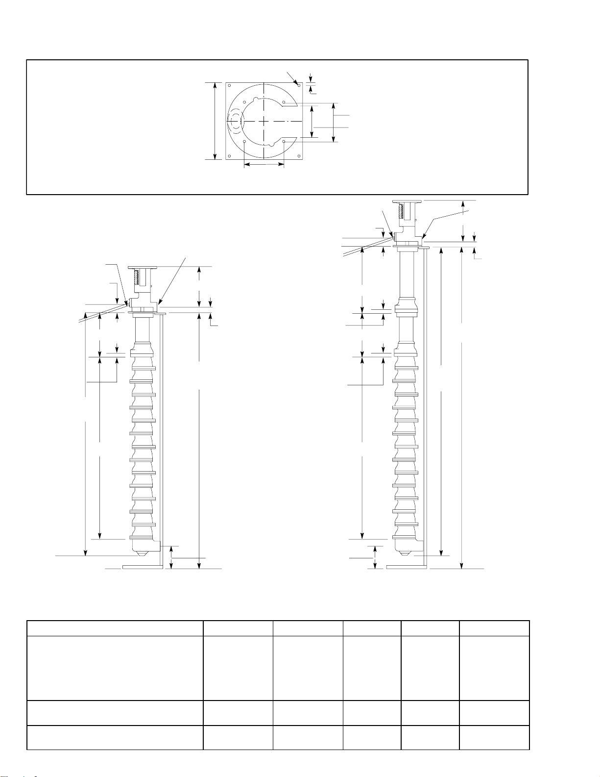
Dimensions
Top View of
Pump Mounting Stand
Stand Weights
220266 92 lb (41.4 kg)
218631 75 lb (33.8 kg)
3/4 npt
Overflow
2.93 in. (74 mm)
B
0.53 in. (13.5 mm) Dia.
11 in.
(254 mm)
Square
Base
2 in. npt Outlet
14.68 in. (373 mm)
5.75 in.
(146 mm)
2.81 in.
(71.4 mm)
0.5 in. (12.5 mm)
2.93 in. (74 mm)
25.5 in. (0.65 m)
1 in. (25 mm)
5.75 in. (146 mm)
4.62 in. (118 mm)
3/4 npt
Overflow
B
2 in. npt Outlet
14.68 in. (373 mm)
2.81 in.
(71.4
mm)
91.5 in.
(2.3 m)
1 in. (25 mm)
62.7 in.
(1.6 m)
A
(Model 223914 Shown)
Standard Size Pumps
(for 60 in. High Tanks)
Pump No. of Stages No. of Bowls A B Weight lb (kg)
223906/224006/224106/224206
223907/224007/224107/224207
223908/224008/224108/224208
223909/224009/224109/224209
223910/224010/224110/224210
223911/224011/224111/224211
223912/224012/224112/224212
223913/224013/224113/224213
223914/224014/224114/224214
236615/236715
30 308059
66.0 in.
(1.7 m)
6.0 in.
(152 mm)
10
11
12
12
14
15
88.25 in.
1 in. (25 mm)
A
6.0 in.
(152 mm)
(Model 224014 Shown)
(2.2 m)
High Profile Size Pumps
(for 85 in. High Tanks)
6
7
8
9
10
10
10
10
10
10
12
12
14
15
33.75 in.
(857 mm)
40.5 in.
(1.03 m)
47.25 in.
(1.2 m)
24.5 in.
(622 mm)
17.75 in.
(451 mm)
11 in.
(279 mm)
210 (95)
212 (96)
214 (96)
215 (97)
217 (98)
218 (98)
220 (99)
222 (100)
223 (100)
225 (102)
03138
Page 31

Notes
31308059
Page 32

Use Only Genuine Graco Parts and Accessories
WARNING
Accessories
Back Pressure Valve 208997
180 psi (1.2 MPa, 12 bar) Controlled Working Pressure
Be sure the valves, plumbing and accessories used
in your system have a working pressure rating at
least as high as the maximum working pressure
rating of the pump.
SERVICE TOOLS
Shaft Holding Tool 207727
For High Profile Pumps.
Shaft Holding Tool 218634
For Standard Pumps.
Shaft Adjusting Tool 178779
Required for setting coupler gap.
Pressing Tool 177219
Used for pressing new bearings into bowls to maintain
proper clearance of bearings.
Checking Tool 177217
Check Fixture 177218
Used with Checking Tool 177217 to check concentricity
of new bearings pressed into impeller bowls.
Spanner Wrench 616637
For holding impellers while
torquing impeller nuts.
Chevron SRI Grease–2 107411
14 oz. Required for lubricating pump.
One tube is included with new pumps.
Assembly Stand 953912
Must be used to assemble the
pump in the proper upright
position, maintaining
alignment.
200 psi (1.4 MPa, 14 bar) Maximum Working Pressure
Stainless Steel. 0.5 in. (12.7 mm) dia. orifice.
1–1/4 in. npt inlet and outlet.
Includes 200 psi (14 bar) pressure gauge.
High Capacity Bag Filters
300 psi (2.1 MPa, 21 bar) Maximum Working Pressure
Heavy-duty, large-area perforated filter bag baskets
with 1/4 in. npt blowdown port on cover. Uses optional
wire mesh liner for dual-stage filtration. Ask your distributor to show you Form No. 300081 for part number
and ordering information.
Fluid Pressure Gauge and Pulsation Dampeners
300 psi (2.1 MPa, 21 bar) Maximum Working Pressure
1–1/4 in. npt inlet and outlet; inline.
Flow rating: 20 gpm (75 liters/min).
Calibrated at 100 centipoise, specific gravity 0.85.
208855 For use with corrosive fluids.
1/4 npt(m) inlet. 300 psi (21 bar)
Maximum Working Pressure
206171 For use with non-corrosive fluids.
1/4 npt(m) inlet. 200 psi (14 bar)
Maximum Working Pressure
Pump Mounting Stand 218631
For Standard Pump Stand
Pump Mounting Stand 220266
For High Profile Pump Stand
Standpipe, SST 223995
32 308059
Diameter: 8 in. (203 mm). Height: 61.125 in. (1.55 m)
Page 33

Accessories
Use Only Genuine Graco Parts and Accessories
Adapter Kit 213049
For 10 and 15 HP Electric Motors. Includes adapter
plate, coupling, coupling insert, and screws and
washers.
NOTE: The size of pump and motor required depends on the viscosity and specific gravity of the fluid to be
pumped, and upon the flow volume and pressure required in the user’s system. Users should contact a Graco
branch or factory office for recommendations.
Electric U–Frame Motors
Adapter Kit 916340
For 20 HP Electric Motors. Includes adapter plate,
coupling, coupling insert, and screws and washers.
Electric T–Frame Motors
Motor H.P. Voltage Rating
521470 3 230/460 Standard
521469 5 230/460 Standard
521468 7.5 230/460 Standard
521467 10 230/460 Standard
521466 15 230/460 Standard
521888 20 230/460 Standard
521455 7.5 600 Standard
51A649 3 CSA 575 Standard
51A650 5 CSA 575 Standard
51A651 7.5 CSA 575 Standard
51A652 10 CSA 575 Standard
51A653 15 CSA 575 Standard
51A654 20 CSA 575 Standard
516821 3 230/460 Premium
516732 5 230/460 Premium
516824 7.5 230/460 Premium
516825 10 230/460 Premium
516731 15 230/460 Premium
516827 20 230/460 Premium
51B297 3 CSA 575 Premium
51B298 5 CSA 575 Premium
51B299 7.5 CSA 575 Premium
51B300 10 CSA 575 Premium
51B301 15 CSA 575 Premium
51B302 20 CSA 575 Premium
114937 10 575 Inverter Duty
51B157 15 230/460 Inverter Duty
51B778 10 230/460 Inverter Duty
116228 10 380 Inverter Duty
51B673 7.5 380V/50Hz Standard
51B674 10 380V/50Hz Standard
51B675 15 380V/50Hz Standard
51B676 20 380V/50Hz Standard
51B677 7.5 380V/50Hz Premium
51B678 10 380V/50Hz Premium
51B679 15 380V/50Hz Premium
51B680 20 380V/50Hz Premium
Motor H.P. Voltage Rating
521441 3 230/460 Standard
521429 5 230/460 Standard
51B296 7.5 230/460 Standard
516826 10 230/460 Standard
521456 15 230/460 Standard
521454 20 230/460 Standard
516822 3 230/460 Premium
516823 5 230/460 Premium
516774 7.5 230/460 Premium
516775 10 230/460 Premium
516776 15 230/460 Premium
516828 20 230/460 Premium
51B681 7.5 380V/50Hz Premium
51B682 10 380V/50Hz Premium
51B683 15 380V/50Hz Premium
51B684 20 380V/50Hz Premium
General Motor Specification:
Class1, Group D, Division 1 Explosion Proof, Temp.
Code T2B, Class F Insulation, Vertical.
33308059
Page 34

Technical Data
Power Supply required 220/575 Volt AC, 3–phase, 50/60 Hz. . . . . . . . . . . . . . . . . . . . . . . . . . . . . . . . . . . . . . . . . . . . . . . .
Flow Rate 0–50 gpm (0–189 liter/min). . . . . . . . . . . . . . . . . . . . . . . . . . . . . . . . . . . . . . . . . . . . . . . . . . . . . . . . . . . . . . . . . . . .
Fluid Inlet and Outlet Size 2 in. npt(f). . . . . . . . . . . . . . . . . . . . . . . . . . . . . . . . . . . . . . . . . . . . . . . . . . . . . . . . . . . . . . . . . . . .
Wetted Parts Stainless Steel, PTFE, Viton, Delrin, PTFE-Coated Iron. . . . . . . . . . . . . . . . . . . . . . . . . . . . . . . . . . . . . .
Viton and Delrin are registered trademarks of the DuPont Co.
34 308059
Page 35

Notes
35308059
Page 36

Graco Standard Warranty
Graco warrants all equipment manufactured by Graco and bearing its name to be free from defects in material and workmanship on the
date of sale by an authorized Graco distributor to the original purchaser for use. With the exception of any special, extended, or limited
warranty published by Graco, Graco will, for a period of twelve months from the date of sale, repair or replace any part of the equipment
determined by Graco to be defective. This warranty applies only when the equipment is installed, operated and maintained in accordance with Graco’s written recommendations.
This warranty does not cover, and Graco shall not be liable for general wear and tear, or any malfunction, damage or wear caused by
faulty installation, misapplication, abrasion, corrosion, inadequate or improper maintenance, negligence, accident, tampering, or substitution of non–Graco component parts. Nor shall Graco be liable for malfunction, damage or wear caused by the incompatibility of
Graco equipment with structures, accessories, equipment or materials not supplied by Graco, or the improper design, manufacture,
installation, operation or maintenance of structures, accessories, equipment or materials not supplied by Graco.
This warranty is conditioned upon the prepaid return of the equipment claimed to be defective to an authorized Graco distributor for
verification of the claimed defect. If the claimed defect is verified, Graco will repair or replace free of charge any defective parts. The
equipment will be returned to the original purchaser transportation prepaid. If inspection of the equipment does not disclose any defect
in material or workmanship, repairs will be made at a reasonable charge, which charges may include the costs of parts, labor, and
transportation.
THIS WARRANTY IS EXCLUSIVE, AND IS IN LIEU OF ANY OTHER WARRANTIES, EXPRESS OR IMPLIED, INCLUDING BUT
NOT LIMITED TO WARRANTY OF MERCHANTABILITY OR WARRANTY OF FITNESS FOR A PARTICULAR PURPOSE.
Graco’s sole obligation and buyer’s sole remedy for any breach of warranty shall be as set forth above. The buyer agrees that no other
remedy (including, but not limited to, incidental or consequential damages for lost profits, lost sales, injury to person or property, or any
other incidental or consequential loss) shall be available. Any action for breach of warranty must be brought within two (2) years of the
date of sale.
Graco makes no warranty, and disclaims all implied warranties of merchantability and fitness for a particular purpose in connection
with accessories, equipment, materials or components sold but not manufactured by Graco. These items sold, but not manufactured
by Graco (such as electric motors, switches, hose, etc.), are subject to the warranty, if any, of their manufacturer. Graco will provide
purchaser with reasonable assistance in making any claim for breach of these warranties.
In no event will Graco be liable for indirect, incidental, special or consequential damages resulting from Graco supplying equipment
hereunder, or the furnishing, performance, or use of any products or other goods sold hereto, whether due to a breach of contract,
breach of warranty, the negligence of Graco, or otherwise.
FOR GRACO CANADA CUSTOMERS
The parties acknowledge that they have required that the present document, as well as all documents, notices and legal proceedings
entered into, given or instituted pursuant hereto or relating directly or indirectly hereto, be drawn up in English. Les parties reconnaissent avoir convenu que la rédaction du présente document sera en Anglais, ainsi que tous documents, avis et procédures judiciaires
exécutés, donnés ou intentés à la suite de ou en rapport, directement ou indirectement, avec les procedures concernées.
Graco Information
TO PLACE AN ORDER, contact your Graco distributor, or call one of the following numbers
to identify the distributor closest to you:
1–800–328–0211 Toll Free
612–623–6921
612–378–3505 Fax
All written and visual data contained in this document reflects the latest product information available at the time of publication.
Graco reserves the right to make changes at any time without notice.
International Offices: Belgium, Korea, China, Japan
Sales Office: Minneapolis
GRACO INC. P.O. BOX 1441 MINNEAPOLIS, MN 55440–1441
www.graco.com
PRINTED IN USA 308059 06/1990, Revised 12/2004
36 308059
 Loading...