

Page 1
INSTRUCTIONS–P
This
manual contains IMPORT
WARNINGS AND INSTRUCTIONS
READ AND RETAIN FOR REFERENCE
ANT
ARTS LIST
308-017
Check-Mate 450 Pumps
With Priming Piston, and Severe-Duty Rod and Cylinder
Model
222-770, Series A, 10:1 Ratio Monark Pump
125 bar (1800 psi) MAXIMUM FLUID WORKING PRESSURE
12.5 bar (180 psi) MAXIMUM AIR INPUT PRESSURE
Model 222-768, Series A, 20:1 Ratio President Pump
250 bar (3600 psi) MAXIMUM FLUID WORKING PRESSURE
12.5 bar (180 psi) MAXIMUM AIR INPUT PRESSURE
Model 222-769, Series A, 34:1 Ratio Senator Pump
238 bar (3400 psi) MAXIMUM FLUID WORKING PRESSURE
7 bar (100 psi) MAXIMUM AIR INPUT PRESSURE
Model 224-660, Series A, 34:1 Ratio Quiet Senator Pump
238 bar (3400 psi) MAXIMUM FLUID WORKING PRESSURE
7 bar (100 psi) MAXIMUM AIR INPUT PRESSURE
Model 222-778, Series A, 55:1 Ratio Bulldog Pump
347 bar (4950 psi) MAXIMUM FLUID WORKING PRESSURE
6.3 bar (90 psi) MAXIMUM AIR INPUT PRESSURE
Rev D
Supersedes C
Model 222-813, Series A, 55:1 Ratio Quiet Bulldog Pump
347 bar (4950 psi) MAXIMUM FLUID WORKING PRESSURE
6.3 bar (90 psi) MAXIMUM AIR INPUT PRESSURE
T
ABLE OF CONTENTS
Warnings 2,
Typical
Installation 5
Operation/Maintenance 6,
Service
Parts
Accessories 22,
Technical
Dimensional
Mounting
Warranty Back Cover.
Toll-Free
.
. . . . . . . . . . . . . . . . . . . . . . . . . . . . . . . . . . . . . . . . .
Installation4. . . . . . . . . . . . . . . . . . . . . . . . . . . . . . . . . . . .
. . . . . . . . . . . . . . . . . . . . . . . . . . . . . . . . . . . . . . . . . . .
Troubleshooting
Required Tools 9.
Disconnecting
Reconnecting
Displacement
Drawings and Lists
Model 222-770 Monark Pump
Model
222-768 President Pump
Model
222-769 & 224-660 Senator Pump
Model
222-778 & 222-813 Bulldog Pump
Displacement
Data and Performance Charts
Model 222-770 Monark Pump
Model
222-768 President Pump
Model
222-769 Senator Pump
Model
224-660 Quiet Senator Pump
Model
222-778 Bulldog Pump
Model
222-813 Quiet Bulldog Pump
Hole Layouts
Graco Phone Numbers
the Displacement Pump9. . . . . . . . . . . . . . .
Pump Service
Pump
.
. . . . . . . . . . . . . . . . . . . . . . . . . . . . . . . . . . . .
Drawing
. . . . . . . . . . . . . . . . . . . . . . . . . . . . . . . . . .
.
. . . . . . . . . . . . . . . . . . . . . . . . . . . .
Chart8. . . . . . . . . . . . . . . . . . . . . . . . . . . . .
. . . . . . . . . . . . . . . . . . . . . . . . . . . . . . . . . . .
the Displacement Pump9. . . . . . . . . . . . . . .
. . . . . . . . . . . . . . . . . . .
. . . . . . . . . . . . . . . . . . . . .
. . . . . . . . . . . . . . . . . . .
.
. . . . . . . . . . . . . . . . . . . . . . . . . .
. . . . . . . . . . . . . . . . . . . . .
. . . . . . . . . . . . . . . . . . .
. . . . . . . . . . . . . . . . . . . .
. . . . . . . . . . . . . . . . . . . . .
. . . . . . . . . . . . . . . . . . . . . . . . . . . . . . .
. . . . . . . . . . . . . . . . . . . . . . . . . . . . . .
. . . . . . . . . . . . .
. . . . . . . . . . .
. . . . . . . . . . .
. . . . . . . . . . . . . . .
. . . . . . . . . . . . . . .
Back Cover.
3
7
10-13.
16.
17.
18.
19.
20, 21
23
24.
25.
26.
27.
28.
29.
30.
31.
Model
222-768
Shown
0423
GRACO INC. P.O. BOX 1441 MINNEAPOLIS, MN 55440-1441
COPYRIGHT 1990, GRACO INC.
Page 2

OBSER
SAFETY
HIGH
PRESSURE FLUID CAN CAUSE SERIOUS INJURY. FOR PROFESSIONAL USE ONL
VE ALL W
ARNINGS. Read And Understand All Instruction Manuals Before Operating Equipment.
W
MOVING PARTS HAZARD
KEEP
HANDS AND FINGERS AWAY FROM THE PRIMING PIST
DURING OPERA
WITH
AIR to reduce the risk of injury!
priming
piston extends beyond the intake cylinder
the
pump. The priming
and whenever the pump is charged with air
tion
severely
injure or amputate a hand or finger
it and the intake cylinder
tween
below
cedure,
any
part of the pump.
TION AND WHENEVER THE PUMP IS CHARGED
piston works under extreme force. During opera
. Always
, before checking, clearing, cleaning, flushing or
On the pump downstroke the
to pull the material into
, the priming piston can
, or break a tool, caught be
follow the
Pressure Relief Pro
ON
servicing
FLUID INJECTION HAZARD
General
This
gun/dispensing valve, leaks or ruptured components can inject fluid
through
injury,
into
NEVER
the
ALWA
ALWAYS
or
removing the spray tip/nozzle or servicing any system equipment.
NEVER try to stop or deflect leaks with your hand or body
Be
use.
Medical
If
any fluid appears
CARE AT
exactly
Note
portant
delay
otic
plastic
Spray
Be sure all spray gun/dispensing valve safety devices are operating
properly
valve;
Safety
Whenever
the
tion,
result
Trigger
Never
moved.
tally
Diffuser
The
tion
Follow the Pressure Relief Procedure, to the right, then remove the
spray
gun firmly to the pail. Using the lowest possible pressure, trigger the
spray
place
Safety
equipment
including the need for amputation. Also, fluid injected or splashed
the eyes or on the skin can cause serious damage.
body
YS have the tip guard in place on
sure all equipment safety devices are operating properly before each
coatings injected directly into the blood stream. Consultation with a
this can cause a malfunction and result in serious bodily injury
generates very high fluid pressure. Spray from the spray
your skin and into your body and cause extremely serious bodily
point
the spray gun/dispensing valve at anyone or at any part of
. NEVER put hand or fingers over the spray tip/nozzle.
the spray gun when spraying.
follow the
Alert––Airless Spray W
ONCE. DO NOT TREA
what fluid was injected.
to Physician:
to treat the injury surgically as soon as possible
treatment to research toxicity
surgeon or reconstructive hand surgeon may be advisable.
Gun/Dispensing V
before each use. Do not remove or modify any part of the
Pressure Relief Procedure
ounds
to penetrate your skin, get
Injection in the skin
T AS A SIMPLE CUT
is a traumatic injury
. T
oxicity is a concern with some ex
alve Safety Devices
, right, before
EMERGENCY MEDICAL
cleaning
.
. T
ell the doctor
.
It is im
. Do
not
gun/
Latch
you stop spraying/dispensing, even for a moment, always
spray gun/dispensing valve safety latch in the closed
making the gun/valve inoperative. Failure to set the safety latch can
in accidental triggering of the gun/valve.
or “safe” posi
set
Guard (if present)
operate the spray
This guard
if it is dropped or bumped.
gun/dispensing valve with the trigger guard re
helps prevent the gun/valve from triggering acciden
(only on spray guns)
spray gun dif
when the tip is not installed. Check the dif
tip. Aim the spray gun into a grounded metal pail, holding the spray
gun. If
the dif
fuser breaks up spray and reduces the risk of fluid injec
the fluid emitted is not dif
fuser immediately
.
fuser operation regularly
fused into an irregular stream, re
ARNINGS
The
air motor piston (located behind the air motor plates or shield ) also
moves
when air is supplied to the motor
the
air motor plates or shield removed.
the
Pressure Relief Procedure
accidentally.
-
-
-
Tip
Guard (only on spray guns)
ALWAYS
tip
does
of
Spray T
Use
spray
dispensing
Relief
NEVER wipe off build-up around the spray tip/nozzle until pressure is
fully
-
-
.
-
-
-
.
-
have the tip guard in place on the spray gun while spraying. The
guard alerts you to the fluid injection hazard and
not prevent,
your body close to the spray tip.
the risk of accidentally placing your fingers or any part
ip/Nozzle Safety
extreme caution when cleaning or
tip/nozzle clogs while
valve safety latch immediately
Procedure
relieved and the
Pressure
To
reduce the risk of serious bodily injury
splashing
always follow this procedure whenever you shut of f the pump,
checking or servicing any part of the spray/dispensing sys
when
when installing, cleaning
tem,
whenever
1.
Engage the spray gun/dispensing valve safety latch.
2.
Shut of
3. Close
tem).
Disengage the gun/valve safety latch.
4.
5. Hold a metal part of the gun/valve firmly to the side of a
grounded
sure.
6. Engage
7. Open the drain valve (required in your system) and/or the
pump bleeder valve, having a container ready to catch the
drainage.
8. Leave
pense
If you suspect that the spray tip/nozzle or hose is completely
clogged,
the
steps above,
or
hose end coupling and relieve pressure gradually
completely.
and then remove the spray tip/nozzle to clean it.
Relief Procedure
in the eyes or on the skin, or injury from moving parts,
you stop spraying/dispensing.
f the air to the pump.
the bleed-type master air valve (required in your sys
metal pail,
the gun/valve safety latch.
the drain valve open until you are ready to
again.
or that pressure has not been fully relieved after following
Now clear the tip/nozzle or hose.
spraying/dispensing, engage the spray gun/
spray gun/dispensing valve safety latch is engaged.
and trigger the gun/valve to relieve pres
VER
Y SLOWL
. NEVER operate the pump with
Before servicing the pump, follow
below to prevent the pump from
helps reduce,
changing spray tips/nozzles. If the
. ALWAYS follow the
, including fluid injection,
or changing spray tips/nozzles, and
Y loosen the tip guard retaining nut
Y.
starting
Pressure
spray/dis
, then loosen
but
-
-
-
-
Page 3
EQUIPMENT MISUSE HAZARD
General
Any
overpressurizing,
ids, or using worn or damaged parts, can cause them to rupture and result
in
fluid injection, splashing in the eyes or on the skin, or other serious bod
ily
injury
NEVER
to
malfunction.
CHECK
worn
Always
ommended
Safety
misuse of
or damaged parts immediately
the spray/dispensing equipment or accessories, such as
modifying parts, using incompatible chemicals and flu
, or fire, explosion or property damage.
alter or modify any part of this equipment; doing so
all spray/dispensing equipment
wear protective eyewear
by the fluid and solvent manufacturer
regularly and repair or replace
.
, gloves, clothing and
.
could cause it
respirator as rec
-
-
-
HOSE SAFETY
High
pressure fluid
ops
a leak,
high
pressure spray emitted from it can cause a fluid injection injury or
other
serious bodily injury or property damage.
ALL FLUID HOSES MUST HA VE SPRING GUARDS ON BOTH
The spring guards help protect the hose from kinks or bends at or
ENDS!
close
to the coupling which can result in hose rupture.
TIGHTEN
fluid can dislodge a loose coupling or allow high pressure spray to be
emitted
from the coupling.
NEVER
use a damaged hose. Before each use, check the entire hose
cuts, leaks,
couplings.
NOT try to recouple high pressure hose or mend it with tape or any
DO
other
device.
fluid.
in the hoses can be very dangerous. If the hose devel
split or rupture due to any kind of wear
all fluid connections securely before each use. High pressure
abrasion,
If any of
bulging cover
these conditions exist, replace the hose immediately
A repaired hose cannot safely contain the high pressure
, or damage or movement of the hose
, damage or misuse, the
-
for
.
System
NEVER
inlet pressure stated on your pump or in the TECHNICAL DATA on
pages
Be
withstand
the
the
Fluid
BE
the
ways
this
HANDLE
move
ner
peratures
Pressure
exceed the recommended working pressure or the maximum air
24-29.
sure that all
maximum
system.
spray/dispensing equipment and accessories are rated to
the maximum working pressure of the pump. DO NOT
working pressure of any component or accessory used in
exceed
Compatibility
SURE that all fluids and solvents used are chemically compatible with
wetted parts shown in the
read the manufacturer’s literature before using fluid or solvent
pump.
AND ROUTE HOSES CAREFULLY. Do not pull on hoses to
equipment. Do not use fluids which are not compatible
tube and cover of the hose. DO NOT expose Graco hoses to tem
above 82C (180F) or below –40C (–40
TECHNICAL DATA on pages 24-29. Al
with the in
F).
-
in
-
-
Hose Grounding Continuity
Proper
hose grounding continuity is essential to maintaining a grounded
spray/dispensing
fluid
hoses at least once a week. If your hose does not
which
specifies the
plier or manufacturer for the maximum resistance limits. Use a resistance
meter
in the appropriate range for your hose to check the resistance. If
the
resistance exceeds the recommended limits, replace it immediately
ungrounded or poorly grounded hose can make your system hazard
An
Also, read
ous.
system. Check the electrical resistance of your air and
maximum electrical resistance, contact the hose sup
FIRE OR EXPLOSION HAZARD
have a tag on it
, below
.
-
.
-
FIRE OR EXPLOSION HAZARD
Static
electricity is created by the high velocity flow of fluid through the
pump and hose. If every part of the spray/dispensing equipment is not
properly
grounded, sparking may occur
hazardous.
power
being sprayed/dispensed, dust particles and other flammable substances,
can
age.
pensing area when there is any chance of igniting fumes still
If
you experience any static sparking or even a slight shock while using
this equipment, STOP SPRA YING/DISPENSING IMMEDIATELY.
Check the entire system for proper grounding. Do not use the system
again
Sparking may also occur when plugging in or unplugging a
supply cord. Sparks can ignite fumes from solvents and the fluid
whether
cause a fire or explosion
Do not plug in or unplug any power supply cords in the spray/dis
until the problem has been identified and corrected.
you are spraying/dispensing indoors or outdoors, and
and serious bodily injury and property dam
Grounding
To reduce the risk of static sparking, ground the pump, object being
sprayed,
spray/dispensing area. CHECK your local electrical code for detailed
grounding
ground
1.
2.
3.
4.
5.
6.
7.
8.
and all other spray/dispensing equipment used or located in the
instructions for your area and type of equipment. BE SURE to
all of this spray/dispensing equipment:
Pump:
use a ground wire and clamp. See Fig 1.
Air hoses:
Fluid hoses:
Air compressor:
Spray
nection
Fluid supply container:
Object being sprayed:
All
Use only metal pails, which are conductive, placed on a grounded
surface.
paper
use only grounded air hoses.
use only grounded fluid hoses.
follow manufacturer’s recommendations.
gun or dispensing valve:
to a properly grounded fluid hose and pump.
according to your local code.
according to your local code.
solvent pails used when flushing,
Do not place the pail on a nonconductive
or cardboard, which interrupts the grounding continuity
, and the system may become
in the air
grounding is obtained through con
according to your local
surface, such as
code.
.
9.
T
o maintain grounding continuity when flushing
, always
sure
firmly
hold a metal part of the spray gun/dispensing valve
to the side of a grounded
metal
pail, then trigger the gun/valve.
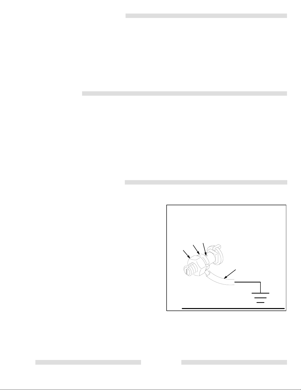
To ground the pump:
To ground the pump, loosen the grounding lug locknut (W) and
(X). Insert one end of a 1.5 mm (12 ga) minimum ground
-
.
washer
wire
(Y) into the slot in lug (Z) and tighten the locknut securely
Fig 1. Connect the other end of the wire to a true earth ground. See
the
ACCESSORIES section to order a ground wire and clamp.
Z
X
W
Y
Fig
-
1
Flushing Safety
Before
flushing, be sure the
grounded. Refer to Grounding, above. Follow the Pressure Relief
Procedure
gun/dispensing
maintain
during
and
on page 2, and remove the spray tip/nozzle from the spray
valve. Always use the
firm metal-to-metal contact between the gun/valve and the pail
flushing to reduce the risk of fluid injection injury
splashing.
entire system and flushing pails are properly
lowest possible fluid pressure, and
or relieving pres
. See
, static sparking
-
IMPORTANT
United
States Government safety standards have been adopted under the Occupational Safety and Health Act. These standards – particularly the Gen
eral
Standards, Part 1910, and the Construction Standards, Part 1926 – should be consulted.
3
-
Page 4
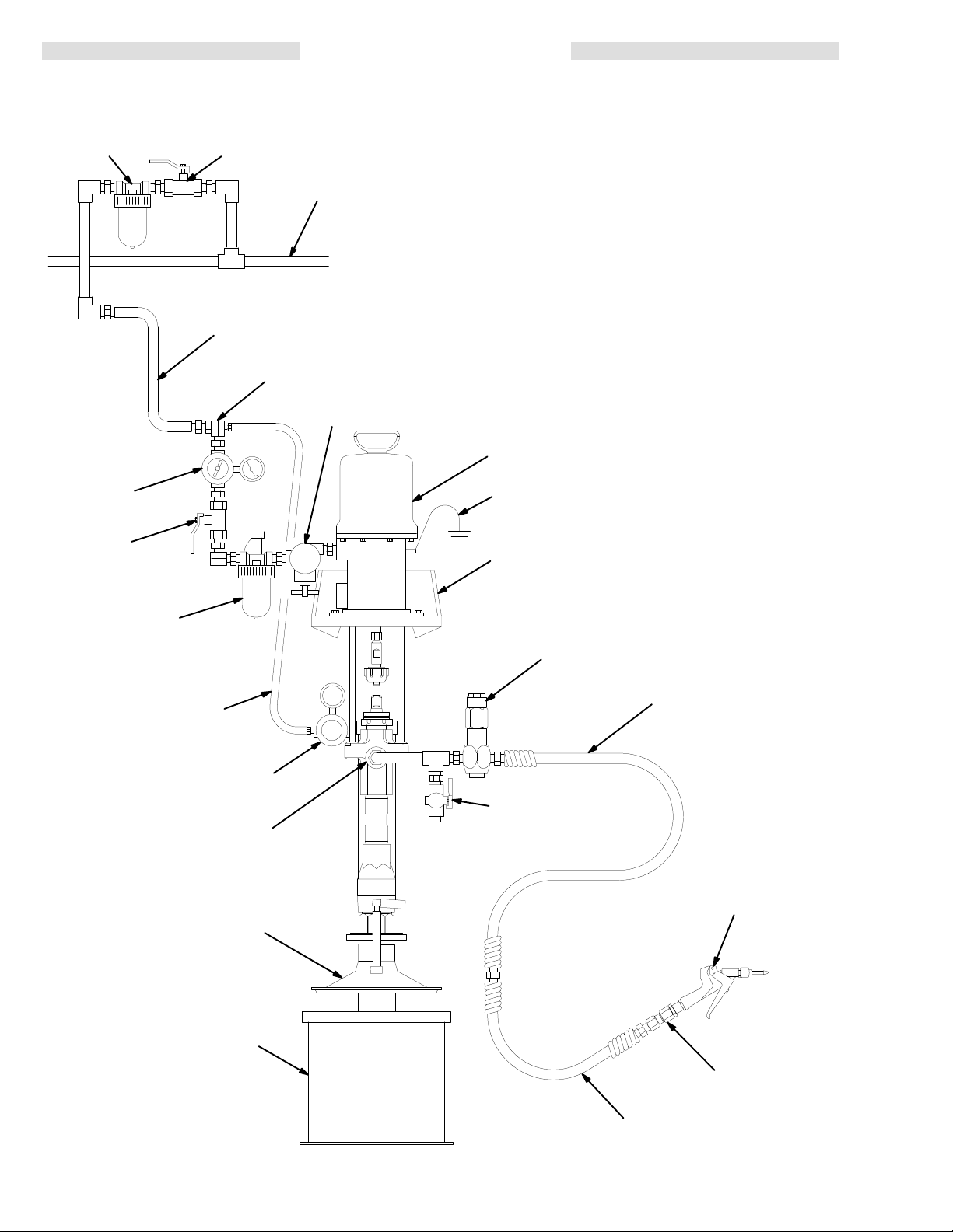
TYPICAL INSTALLATION
KEY
J
H
G
K
MAIN AIR LINE
PUMP AIR
SUPPL
Y HOSE
D
E
A Pump
B 19
C
D
E
F
G Bleed-T
H
J
K Bleed-T
L
M
N
P Gun/V
Y
Liter (5 Gal.) Pail Ram
Wiper Plate
Air Manifold
Pump Runaway V
Air Line Lubricator
(required, for pump)
Pump Air Regulator
Air Line Filter
Fluid Drain V
Fluid Pressure Regulator
Gun or Dispensing V
Ground Wire (required; see page 3 for
installation instructions)
A
Y
B
alve
ype Master Air V
ype Master Air V
alve (required)
alve Swivel
alve
alve (for accessories)
alve
F
RAM AIR
SUPPL
RAM AIR REGULA
PUMP FLUID OUTLET
19 LITER (5 GAL.) P
Y HOSE
M
MAIN FLUID HOSE
TOR
L
N
C
AIL
4
P
FLUID WHIP HOSE
0218
Page 5

INSTALLATION
NOTE: Reference numbers and letters in parentheses
in
the text refer to the callouts in the figures and
the
parts drawing.
See pages 22 and 23 for accessories available
from
Graco. If
be
sure they
rated
to meet the system’
The Typical Installation shown on page 4 is
for selecting and installing system components and accessories. Contact your Graco representative or Graco
Technical Assistance (see back page) for assistance in
designing
SYSTEM ACCESSORIES
Refer to the T
A
valve
sories help reduce the risk of serious bodily injury
including
injury from moving parts if you are adjusting or re
pairing the pump.
The
between this valve and the pump after the air is shut
off. Trapped air can cause the pump to cycle unex
pectedly.
The fluid drain valve assists in relieving fluid pres
sure in the displacement pump, hose, and gun.
Triggering the gun to relieve pressure may not be
sufficient.
Air and Fluid Hoses
Be sure all air and fluid hoses are properly sized and
pressure-rated for your system. Use only grounded air
and
both ends. Use of a short whip hose between the main
fluid
Mounting Accessories
Mount the pump (A) to suit the type of installation
planned. The pump dimensions and mounting hole layouts
If you are mounting the pump on a ram (B), refer to the
manual
eration instructions. The ram shown in the T
lation is a 222-781 19 liter (5 gal.) pail ram, used with a
wiper
also requires an air supply hose and an air manifold
It
which divides the main air supply into separate lines for
the pump and the ram.
By using Pump Mounting Kit 222-776, you can also
mount the pump on Floor Stand 222-780, 200 liter (55
gal.) Ram 223-634, or Inductor 222-635. See Accessories
a system to suit your particular needs.
ypical Installation drawing on page 4.
bleed-type master air valve (G) and a fluid drain
(L) are required in your system. These
splashing in the eyes or on the skin, and
bleed-type master air valve relieves air trapped
Locate the valve close to the pump.
fluid hoses. Fluid hoses must have
hose and the gun allows freer gun movement.
are shown on pages 30 and 31.
supplied with the ram unit for
plate (C).
for further information.
you supply your own accessories,
are adequately sized and pressure-
s requirements.
only a guide
WARNING
acces
-
-
-
-
spring guards on
installation and op
ypical Instal
The ram shown includes an air regulator
(D),
Air Line Accessories
Install
the following
Typical
Fluid Line Accessories
Install
the T
-
-
.
Installation, using adapters as necessary:
A pump runaway valve (E
running
the
ly
An air line lubricator (F)
tor
A
system to relieve air trapped between it and the air
motor
left).
the pump, and is located downstream from the air
regulator.
An
pressure by adjusting the air pressure to the pump.
Locate
from
An air line filter (J) removes harmful dirt and moisture
A second bleed-type air valve (K) isolates the air
line
all other air line accessories.
A fluid drain valve (L) is required in your system to
relieve fluid pressure in the hose and gun (see the
WARNING at left). Screw the drain valve into the
open
the
up
A fluid regulator (M) controls fluid pressure to the
gun/valve,
A gun or valve (N) dispenses the fluid. The gun
shown in the Typical Installation is a dispensing gun
for
A gun swivel (P)
Before operating the pump, ground the system as
explained under FIRE OR EXPLOSION HAZARD
and
too fast and automatically shuts off the air to
motor
damaged. Install closest to the pump air inlet.
lubrication.
bleed-type master air valve (G)
when the valve is closed (see
Be sure the bleed valve is
air
regulator (H)
the regulator close
the bleed-type master air valve.
from the compressed air supply
accessories
the following accessories in the positions shown in
ypical Installation, using adapters as necessary:
branch of a tee mounted
drain valve pointing down, but so the handle points
when the valve is opened.
highly viscous fluids.
Grounding
accessories in the order shown in the
) senses when the pump is
. A pump which runs too fast can be serious
provides automatic air mo
is required in your
the
WARNING
easily accessible from
controls pump speed and outlet
to the pump, but
for servicing. Locate upstream from
in the fluid line. Install
and dampens pressure surges.
allows freer gun movement.
upstream
.
-
-
at
GROUNDING
WARNING
on page 3.
5
Page 6

OPERATION/MAINTENANCE
WARNING
Pressure Relief Procedure
T
o reduce the risk of serious bodily injury
fluid
injection, splashing in the eyes or on the skin, or
injury from moving parts, always follow this proce-
whenever you shut of
dure
ing
or servicing any
tem, when installing, cleaning or changing spray
tips/nozzles, and whenever you stop spraying/dispensing.
1. Engage the spray gun/dispensing valve safety
latch.
of
2. Shut
3. Close
your
4.
Disengage the gun/valve safety latch.
5. Hold a metal part of the gun/valve firmly to the
side
valve
6.
Engage the gun/valve safety latch.
7. Open the drain valve (required in your system)
and/or the pump bleeder valve, having a container
8. Leave
spray/dispense
f the air to the pump.
the bleed-type master air valve (required in
system).
of a grounded metal pail, and trigger the gun/
to relieve pressure.
ready to catch the drainage.
the drain valve open until you are ready
part of the spray/dispensing sys
again.
f the pump, when check
, including
-
-
to
If you suspect that the spray tip/nozzle or hose is
completely clogged, or that pressure has not been
fully
relieved after following the
SLOWLY
end coupling and relieve pressure gradually , then
loosen
Packing Nut/W
Fill
the packing nut/wet-cup (2)
Seal
Liquid (TSL) or compatible solvent. See Fig. 2. Ad
the packing nut weekly so it is just snug; do not over
just
tighten. Follow the Pressure Relief Procedure W arn-
ing
above before adjusting the packing nut.
Flushing the Pump
pump is tested with lightweight oil, which is left in to
The
protect the pump parts. If the fluid you are using may be
contaminated
before using the pump.
vent
For your safety , read the warning section, FIRE
OR
ing,
loosen the tip guard retaining nut or hose
completely
EXPLOSION HAZARD
and follow all recommendations given there.
. Now clear the tip or hose.
et–Cup
by the oil, flush it out with a compatible sol
WARNING
steps above,
1/3 full with Graco Throat
on page 3 before flush
VER
Y
-
WARNING
Moving
other body parts. When the pump is operating, the
priming
the air motor piston (located behind the air motor
plates or shield) move. See Fig. 2. Therefore,
NEVER
or
away
Before attempting to clear an obstruction from the
priming piston (25) or service the pump, follow the
Pressure
vent
Cycle
the
gun/dispensing
The
is
released.
If
the pump fails to prime properly
(35)
the
hole.
NOTE: When changing fluid containers with the hose
To reduce the risk of fluid injection, DO NOT use
your hand or fingers to cover the bleeder hole (R)
when
With the pump and lines primed, and with adequate air
-
pressure and volume supplied, the pump will start and
-
stop
Use the
the fluid pressure. Always use the lowest air pressure
necessary to get the desired results. Higher pressures
cause
To
which could result in component rupture and cause
serious
MAXIMUM INCOMING AIR PRESSURE to the
pump
parts can pinch or amputate your fingers or
piston (25) (located at the
operate the pump with the air motor
shield removed, and keep your fingers and hands
from the priming piston.
Relief Procedure W
the pump from starting accidentally
the pump slowly until all the air is pushed out
pump and hoses are fully primed. Release the spray
valve trigger and engage the safety
pump should stall against pressure when the
slightly
valve, as a priming valve until the fluid appears at the
as the gun/valve is opened and closed.
. Use the bleed hole (R), on the underside of
See Fig 2. Close the bleeder valve.
and
gun already
(35),
to assist in priming the pump and venting air
before it enters the hose. Close the bleeder valve
when
all air has been eliminated.
priming the pump.
air regulator (H) to control the pump speed and
premature tip/nozzle and pump wear
reduce the risk of overpressurizing your system,
bodily
injury, NEVER exceed the specified
(see the T
primed, open the bleeder valve
WARNING
WARNING
echnical Data on pages 24-29).
pump intake) and
arning
, open the bleeder valve
at left to
.
.
plates
pre
latch.
trigger
-
and
Starting and Adjusting the Pump
the
See
using
arate instructions for those components for set-up and
operation
Lower the pump into a fluid container . Be sure the air
regulator
are
part of the spray gun/dispensing valve (N) firmly to the
side
Now slowly open the air regulator until the pump starts.
6
TYPICAL INST
a ram or wiper plate with the pump, refer to the sep
instructions.
(H)
and pump’
closed. Then open the bleed
of
a grounded metal pail and hold the trigger open.
ALLATION
s bleed-type master air valve (G)
on page 4.
valve (G). Hold a metal
If you are
Never allow the pump to run dry of the fluid being
pumped. A dry pump will quickly accelerate to a high
speed,
-
possibly damaging itself. A pump runaway valve
(E),
which shuts of
accelerates
the Typical Installation on page 4 and ACCESSORIES
pages 22 and 23. If your pump accelerates quickly
on
is
running too fast, stop it immediately and check the fluid
supply.
pumped into the lines, refill the container and prime the
pump and the lines with fluid, or flush and leave it filled
with
the
If the supply container is empty and air has been
a compatible solvent. Be sure to eliminate all air from
fluid system.
f the air supply to the pump if the pump
beyond the pre-set speed, is available. See
, or
Page 7
Shutdown and Care of the Pump
For
overnight shutdown, follow the Pressure Relief Pro
cedure
bottom
Warning
of the stroke to prevent the fluid from
on page 6. Always
stop the pump at the
drying on the
exposed displacement rod and damaging the throat
packings.
Always flush the pump before the fluid dries on the displacement
-
rod. Never leave water or water-based fluid in
the pump overnight. First, flush with water or a compatible solvent, then with mineral spirits. Relieve the pressure,
but leave the
the
parts from corrosion.
mineral spirits in the pump to protect
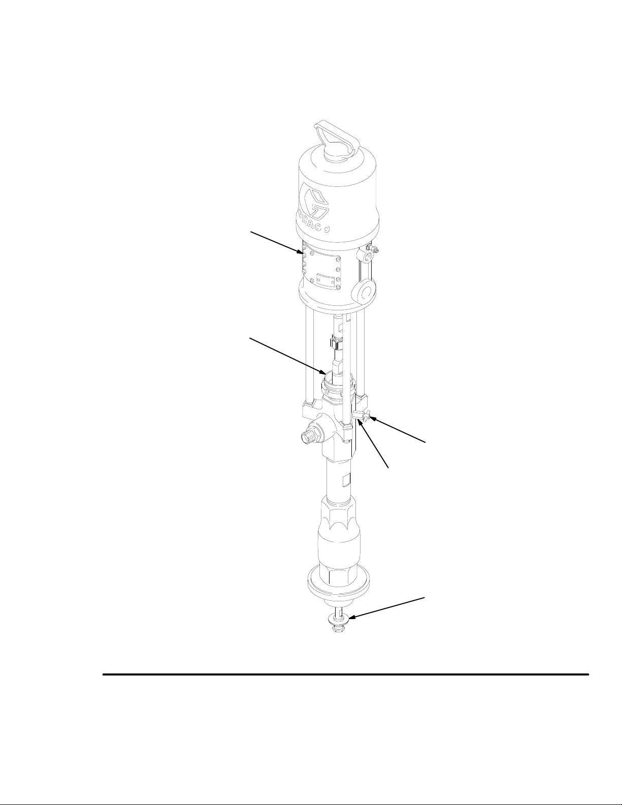
AIR MOT
OR PLA
TE
2
35
R
Fig 2
25
0423
7
Page 8
TROUBLESHOOTING
CHART
PROBLEM CAUSE SOLUTION
Pump
fails to operate
Restricted line or inadequate air supply
Clear; see
TECHNICAL DATA
on pages 24-29.
Pump operates, but out-
low on both strokes
put
Pump operates, but out-
low on downstroke
put
Pump operates, but out-
low on upstroke
put
Erratic or accelerated
speed
pump
Obstructed fluid hose or gun/valve;
fluid hose ID is too small
Fluid dried on the displacement rod
Dirty
, worn, or damaged motor parts
Restricted line or inadequate air supply
Obstructed fluid hose or gun/valve;
fluid hose ID is too small
Bleeder valve open
Air leaking into supply container
Fluid too heavy for pump priming
W
orn packings in displacement pump
Fluid too heavy for pump priming
Held open or worn intake valve or seals
Held open or worn piston valve or seals
Exhausted fluid supply
Fluid too heavy for pump priming
Open, clear*; use hose with larger ID.
Clean; always stop pump at bottom of stroke;
keep wet-cup 1/3 filled with compatible solvent.
Clean or repair; see air motor manual, supplied.
Clear; see
TECHNICAL DATA
on pages 24-29.
Open, clear*; use hose with larger ID.
Close.
Check wiper plate or ram plate seal.
Use bleeder valve (see page 6).
Use inductor or ram.
Remove piston spacer (33).**
Replace packings.
Use bleeder valve (see page 6).
Use inductor or ram.
Remove piston spacer (33).**
Clear valve; replace seals.
Clear valve; replace seals.
Refill and prime.
Use bleeder valve (see page 6).
Use inductor or ram.
Remove piston spacer (33).**
Held open or worn piston valve or seals
Held open or worn priming piston
W
orn packings in displacement pump
*To
determine if the fluid hose or gun is obstructed, follow the
container
when
**
Remove the piston spacer (33) only as a last resort, as the pump may not perform well without it.
NOTE:
at the pump fluid outlet to catch any fluid. T
the air is turned on, the obstruction is in the fluid hose or gun.
If you experience air motor icing, call Graco T
Pressure Relief Procedure W
urn on
the air just enough to start the pump (about 1.4-2.8 bar [20-40 psi]).. If the pump starts
echnical Assistance
Clear valve; replace seals.
Clear; service.
Replace packings.
(1-800-543-0339).
WARNING
Pressure
To
tion,
ing
the
dispensing system, when installing, cleaning or changing
spray tips/nozzles, and whenever you stop spraying/dispensing.
1. Engage
2.
3. Close the bleed-type master air valve (required in your
4. Disengage
Relief Procedure
reduce the risk of serious bodily injury
, including fluid injec
splashing in the eyes or on the skin, or injury from mov
parts, always follow this
pump, when checking or servicing
procedure whenever you shut of
any part of the spray/
the spray gun/dispensing valve safety latch.
Shut of
f the air to the pump.
system).
the gun/valve safety latch.
-
5.
f
Hold a metal part of the gun/valve firmly to the side of a
grounded
pressure.
6. Engage
7. Open
the gun/valve safety latch.
the drain valve (required
pump bleeder valve, having a container ready to catch
drainage.
the
8. Leave
If
you suspect that the spray tip/nozzle or hose is completely
clogged,
lowing
the drain valve open until
dispense
again.
or that pressure has not been fully relieved after fol
the steps above,
retaining nut or hose end coupling and relieve pressure
gradually,
then loosen completely
arning
below
. Disconnect the fluid hose
metal
pail, and trigger the gun/valve to relieve
in your system) and/or the
you are ready to spray/
VER
Y SLOWL
Y loosen the tip guard
. Now clear the tip or hose.
and place a
-
8
Page 9
SERVICE
REQUIRED TOOLS
T
orque wrench
Bench vise, with soft jaws
Hammer
Rubber mallet
13 mm (1/2”) dia. brass rod
O-ring pick
11
mm, 12 mm, 19 mm, 22 mm, 26 mm, and 28 mm
open-end
17 mm box or socket wrench
32 mm crow’s-foot wrench
400 mm adjustable wrench
Set of adjustable wrenches
Thread lubricant
Anaerobic thread sealant
wrenches
DISCONNECTING THE DISPLACEMENT PUMP
WARNING
KEEP HANDS AND FINGERS AWAY FROM
THE
PRIMING PISTON DURING OPERA TION AND
WHENEVER
THE PUMP IS CHARGED WITH AIR
to reduce the risk of injury! On the pump down-
stroke
the priming piston extends beyond the intake
cylinder
ing
tion
to pull the material into the pump. The prim
piston works under extreme
force. During opera
and whenever the pump is charged with air
-
-
, the
priming piston can severely injure or amputate a
or finger
hand
the
intake cylinder
, or
break a tool, caught between it and
. Always follow the
Pressure Re
-
lief Procedure Warning on page 8, before check-
ing,
clearing, cleaning, flushing or
of
the pump.
servicing any part
The air motor piston (located behind the air motor
or shield) also moves when air is supplied to
plates
the motor. NEVER operate the pump with the air
motor plates or shield removed. Before servicing
the pump, follow the Pressure Relief Procedure
Warning
ing
1. Flush
tom
dure
on page 8, to prevent the
accidentally
.
pump from start
the pump if possible. Stop the pump at the bot
of its stroke.
W
arning
Follow the
on page 8.
Pressure Relief Proce
-
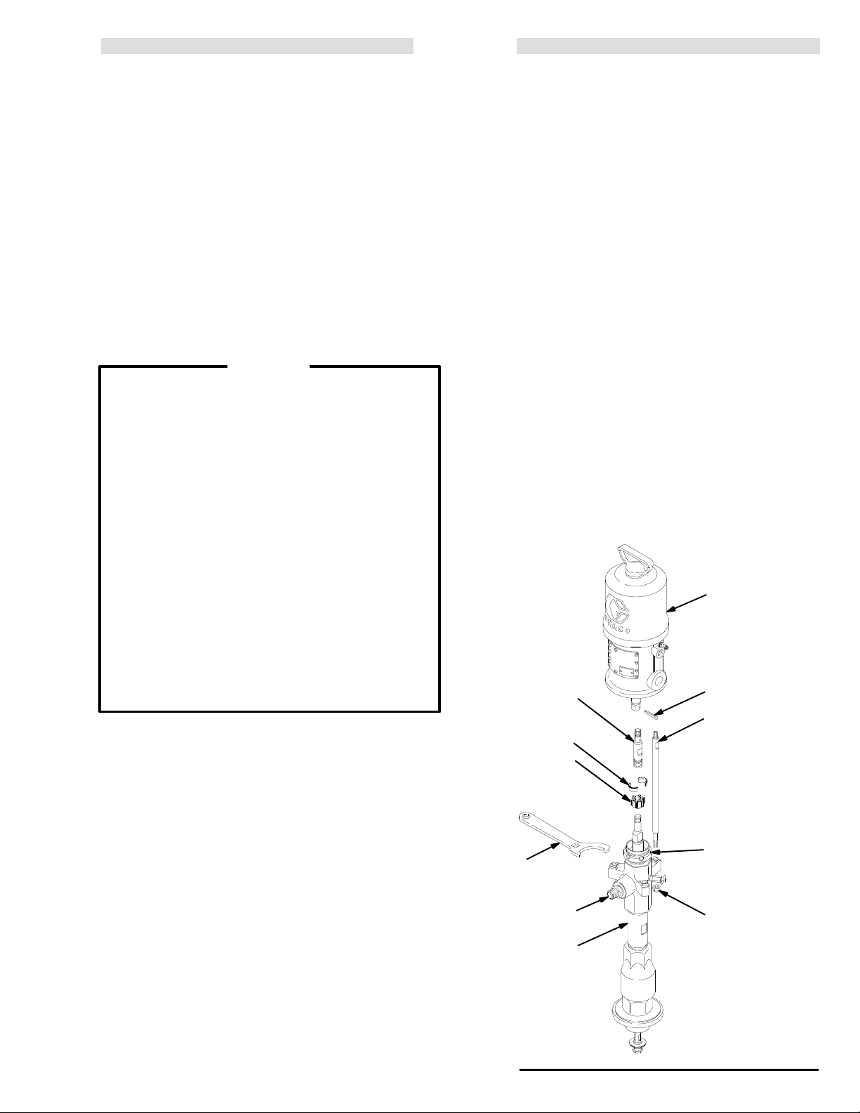
2. Disconnect the air hose. Hold the fluid outlet fitting
(8)
with a wrench
to keep it from being loosened while
you disconnect the fluid hose. Remove the pump
from its mounting. Note the relative position of the
pump’s
fluid outlet to the air motor’s air inlet.
3. Using an adjustable wrench, unscrew the coupling
nut
(104) from the connecting rod (103). Remove the
coupling
4. Hold
turning.
17
locknuts
the
5. Refer
service
manual,
collars (105). See Fig 3.
the tie rod flats with a wrench to keep them from
Use the wrench provided with the
pump (or a
mm box or socket wrench) to unscrew the tie rod
(106) from the tie rods (102). Carefully
displacement
pump (107) of
f the air motor (101).
pull
to page 10 for displacement pump service. T
the air motor
, refer to the
separate air motor
supplied.
RECONNECTING THE DISPLACEMENT PUMP
1. Orient
the pump’
as was noted in step 2 under
let
s fluid outlet to the air motor’s air in
Disconnecting the
Displacement Pump. Position the displacement
pump
(107) on the tie rods (102). See Fig 3.
NOTE: If
you removed the tie rods (102) from the air
tor (101) or air motor adapter plate, reinstall
them
using an 1
1 mm wrench. T
orque
20-25 N.m (15-18 ft-lb) on President pumps, and
36-45
N.m (27-33 ft-lb) on all other pumps.
2. Screw
the locknuts
(106) onto the tie rods (102) and
torque to 27-34 N.m (20-25 ft-lb), using the wrench
provided
(or a 17 mm box or socket wrench).
3. Place the coupling nut (104) on the displacement
then place the coupling collars (105) in the nut.
rod,
Screw
the coupling nut onto the connecting rod (103)
loosely. Hold the connecting rod flats
to keep it from turning. With an adjustable wrench,
the coupling nut to 50-61 N.m (37-45 ft-lb).
torque
4. Using a torque wrench in the square hole of the
supplied
wrench (1
10), torque the packing
45-53 N.m (33-39 ft-lb).
5. Mount
the pump and reconnect all hoses. Reconnect
the
ground wire if it was
on the air and run the pump slowly
Turn
disconnected during repair
6. Fill the packing nut/wet-cup 1/3 full of Graco Throat
Seal
Liquid or compatible solvent.
101
103
111
102
-
-
104
TORQUE TO
50-61 N.m
(37-45 ft-lb)
105
TORQUE TO
20-25 N.m
(15-18 ft-lb)
ON PRESIDENT
PUMPS;
36-45 N.m
(27-33 ft-lb) ON ALL
OTHER PUMPS
2
110
8
107
TORQUE TO
45-53 N.m
(33-39 ft-lb)
106
TORQUE TO
27-34 N.m
(20-25 ft-lb)
MODEL 222-768
PRESIDENT PUMP
SHOWN
o
Fig 3
9
mo
the rods to
with a wrench
nut (2) to
.
0424
-
-
.
Page 10
DISPLACEMENT
PUMP SER
VICE
Disassembly
When
disassembling the pump, lay out all removed parts
in
sequence, to ease reassembly
NOTE: Repair
Kit 222-773 is available to replace the pis
ton
and intake valve seals. For
. Refer to Fig 6.
the best results,
use all the new parts in the kit. Kit parts are
marked
with one asterisk, for example (1
1*).
Repair Kit 222-774 is available to replace the
throat
packings. For the best results, use all the
new
parts in the kit. Kit parts are marked with two
asterisks,
for example (3**).
1. Remove the displacement pump from the air motor
as explained on page 9. Place the pump in a vise,
the jaws on the outlet housing (10).
with
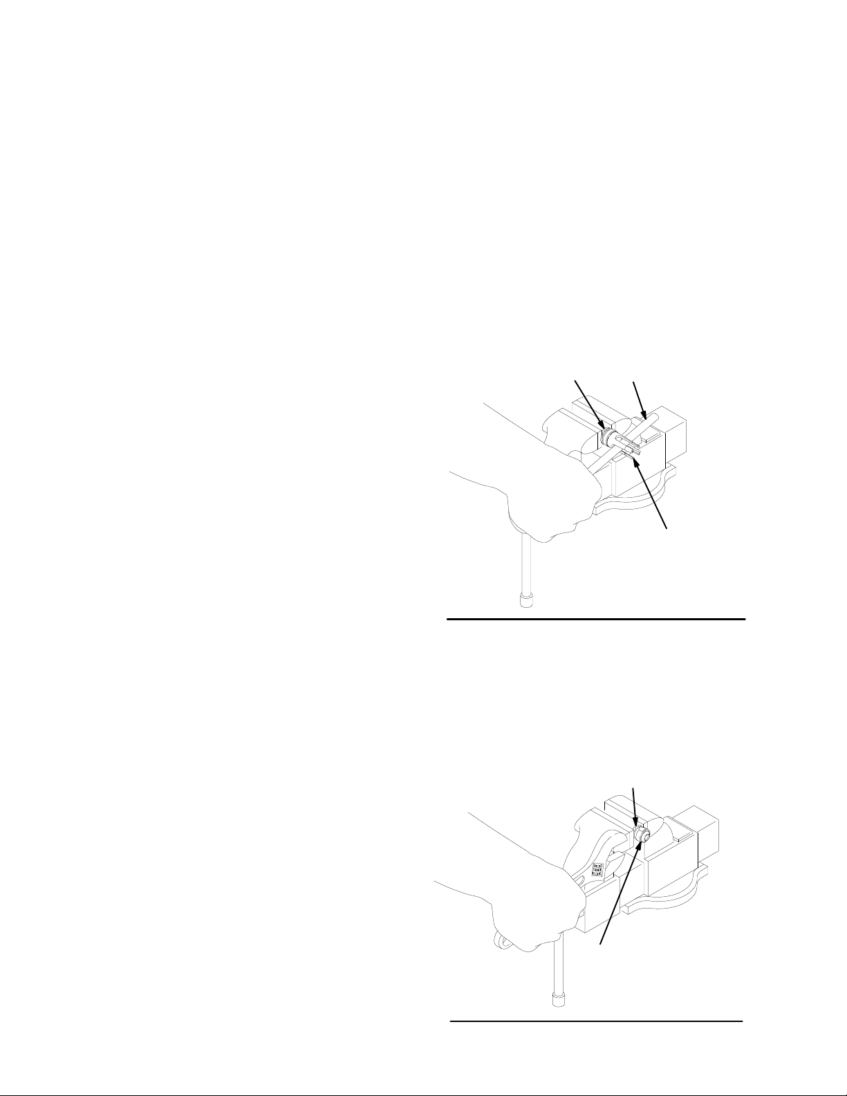
2. Hold
the flats of the priming piston rod (24) with a 12
mm wrench. Using a 22 mm wrench, unscrew the
priming
and
of
other
piston nut (30). Slide the priming piston (25)
piston guide (31) of
f the rod.
Inspect the surfaces
the guide (31) and piston (25) for scoring, wear
damage.
, or
10. Inspect the outer surfaces of the displacement rod
(1) and priming piston rod (24) for wear , scoring or
other damage by holding them up to the light at an
angle
or running a finger over the surface.
11. Use
-
a vise with soft jaws
(1)
by its flats.
Place a 19 mm wrench on the flats of
to hold the displacement rod
the piston and unscrew the piston (13) and priming
piston rod (24) from the displacement rod (1). Remove
the spacer (33). Disassemble the piston guide
(14)
from the piston (13).
12.
It is not necessary to remove the priming piston rod
(24) from the piston (13) unless your inspection reveals scoring, wear, or other damage to either part.
To disassemble, place the piston flats in a vise and
unscrew
13. Place
a
13 mm (1/2 in.) dia. brass rod,
the rod, using a 12 mm wrench on the flats.
the flats of the piston seat (16) in a vise. Using
unscrew the piston
guide (14) from the piston seat (16). See Fig 4. Re-
the piston seal (15); always replace with a new
move
one. Inspect the mating surfaces of the piston (13)
and
piston seat (16) for nicks, scoring or wear
BRASS ROD
16
.
3. Loosen the packing nut (2) using the wrench (1 10)
supplied,
take
4. Unscrew
der
or a hammer and brass rod. Remove the in
cylinder (23), using an adjustable wrench.
the intake valve housing (17) from the
(12),
using an adjustable wrench. Pull the hous
cylin
ing off the pump. The intake check valve assembly
(S)
should slide down the priming piston rod (24)
as
you remove the housing; if it does not slide easily ,
firmly
tap on
the top of the housing (17) with a rubber
mallet
to loosen.
5. Use an o-ring pick to remove the seal (21) from the
intake valve housing (17). Discard the seal; use a
new one for reassembly. Pull the intake valve seat
(22)
out the bottom of
the housing (17). If the seat is
difficult to remove, insert a hammer and brass rod
through the top of the housing and drive the seat
out.Take
(S) as it comes free, and set it aside for later
6. Push
care not to drop the check valve assembly
the displacement
rod (1) down as far as possi
.
ble, then pull it and the priming piston rod (24) out of
the
outlet housing (10) and cylinder (12).
7. Remove the packing nut (2), throat packings (3, 5)
and glands (4, 6) from the outlet housing (10). DO
NOT
remove the
from
the housing unless they need replacement.
fluid outlet nipple (8) and o-ring (9)
-
-
-
-
14
Fig 4
14. To
disassemble the intake check valve (S), place the
nut
(18) in a vise and unscrew the intake valve body
(19),
using a 28 mm wrench. See Fig 5. Remove the
seals
(42, 20) from the nut and from the valve body;
always
replace them with new ones. Inspect the mat
ing surfaces of the intake valve body (19) and seat
(22)
for wear
NOTE: The
require
, scoring, or other damage.
seal (42) is press-fit in the nut
cutting to ease removal.
(18) and may
18
0205
-
8. Unscrew
housing.
the handle of the bleeder valve (35) from
Clean the threads and the bleed hole in the
valve housing. It is not necessary to remove the
housing from the outlet housing (10).
valve
9. Use
a 400 mm adjustable wrench on the flats of the
pump
cylinder
outlet
housing (10). Remove the
the
inside surface of the cylinder for wear
other
damage by holding it up to the light at an angle
or
running a finger over the surface.
(12) and unscrew the cylinder from the
o-rings (1
10
its
1). Inspect
, scoring or
19
0206
Fig 5
15. Inspect all parts for damage and clean with a compatible
solvent. T
o reassemble, refer to page 12.
Page 11

THROAT PACKING DET
AIL
**4
**5
**6
REMOVE
ONL
IF DAMAGED.
*9
8
Y
LIPS OF
V-PACKINGS
MUST F
DOWN
3**
12
ACE
1
2
10
VALVE HOUSING
35
VAL
VE HANDLE
(REMOVE AND CLEAN)
11*
(REF)
33
14
12
(REF)
13
DETAIL
INT
OF PIST
ON AND
AKE CHECK V
ALVE
1
23
*11
17
22
*21
24
31
25
SEE
AT
SEE
AT
DET
RIGHT
DET
RIGHT
AIL
AIL
(SEE
FIG 5)
*15
16
17
(REF)
42
S
18
*20
19
24
(REF)
Fig 6
30
0425A
11
Page 12

Reassembly (Refer to Fig 7)
PTFE
PTFE
1. Place
2. If
3. Use
NOTE: The piston spacer (33) is not required when
4. Screw the handle of the bleeder valve (35) into the
NOTE: It
5. Lubricate
6. Lubricate
7. Carefully
a 13 mm (1/2 in.) dia. brass rod lengthwise in
vise. Install a new piston seal (15*) on the piston
seat.
Apply thread
seat. Place the piston guide (14) securely on the
brass
rod. Using
ton seat (16) into the piston guide. Torque to 27-34
N.m (20-25 ft-lb).
it was necessary to remove the priming piston
(24)
from the piston (13), apply thread sealant to the
threads
a
and screw the rod into the piston. T orque to 45-53
N.m (33-39 ft-lb).
(1)
ing
de/seat on the piston (13). Apply thread sealant to
the threads of the displacement rod, and screw the
piston
on the flats of the piston. T orque to 120-130 N.m
(88-95 ft-lb). There will be a small gap between the
top
valve housing. The handle has two sets of threads.
When
ly
inder (12). Apply thread lubricant to the top threads of
the
the cylinder, screw it into the outlet housing (10).
Torque
them in the outlet housing (10) one at a time in the
following
of the rod. Place the flats
vise. Hold the flats of the rod with a 12 mm
a vise with soft jaws
by its flats. Install the spacer (33, see the
note) on the rod. Install the
assembly onto the rod, using a 19 mm wrench
of the piston (13) and the shoulder of the rod
pumping
lion
centipoise.
reassembling,
into the valve housing.
is not ordinarily necessary to remove the outlet
nipple
(8)
replaced because of damage, lubricate the o-
(9*) and place it on the nipple (8). Screw the
ring
fitting into the outlet housing (10). T orque to
70-75 N.m (51-55 ft-lb).
the o-rings (1
cylinder
to 256-297 N.m (190-220 ft-lb).
the throat packings and glands, and install
order
ing down:
(5**),
UHMWPE (5**), and female gland (4**).
(3**),
thread lubricant to the packing nut (2) and install the
nut
loosely in the outlet housing.
insert the displacement
tom
of the cylinder (12). Push the rod up into the cyl
inder
and through the outlet housing (10), until it pro
trudes from the packing nut (2). Be careful not to
sealant to the threads of the piston
a 32 mm crow’
to hold the displacement rod
fluids with a viscosity greater than 1 mil
be sure to screw the handle ful
and o-ring (9*). However
1*) and install them on the
. Using a 400 mm wrench on the flats of
,
with the lips of the v-packings fac
male gland (6**), UHMWPE v-packing
v-packing (3**),
s-foot, screw the pis
rod
of the piston (13) in
wrench,
follow
assembled piston gui
(1).
, if they were
cyl
UHMWPE (5**),
Apply
rod (1) into the bot
a
damage the piston seal (15*) while performing this
step.
8. Apply thread lubricant to the bottom threads of the
cylinder (12). Be sure the o-ring (11*) is in place on
the
-
9. With
10. Apply
-
-
11. Lubricate a new intake valve seal (20*) and slide it
12. Place
-
-
13. Position the intake valve seat (22) so its large bev-
-
14. Apply
15. Slide
-
16. Reconnect the displacement pump to the air motor
-
-
-
17. Allow
cylinder
onto
the priming piston rod (24) and screw it onto the
cylinder, using an adjustable wrench. T orque to
256-297
the beveled side facing up, press the seal (42)
into the recess of the intake packing nut (18) until it
snaps
with
or slightly recessed into the face of the packing
nut.
(18).
With the threads facing down toward the pump
intake, slide the nut up onto the priming piston rod
until it clears the flats of the rod.
(24)
onto the rod, being careful not to damage the seal
when
up
until it reaches the packing nut (18). Apply
to the female threads of the intake valve body (19),
and
slide it onto the rod until it reaches the nut (18).
(18) and a 28 mm wrench on the flats of the valve
body (19). Screw the nut into the body, making certain
they remain in position above the flats of the rod
(24). Torque to 45-53 N.m (33-39 ft-lb). Slide the as
sembled
until
it
to
high friction between the seal and rod.
side faces down toward the pump intake.
eled
the
seat (22) onto the priming piston rod (24) and into
the
intake
lip of the housing. Lubricate a new seal (21*) and
er
push
of
the seat (22).
inder (23) and screw the cylinder into the intake valve
housing
256-297
until
it stops. Then install the priming piston (25) with
the flat side of the priming piston (25) facing up toward
of the priming piston rod (24). Hold the rod steady
with a 12 mm wrench on the flats, and screw the
priming piston nut (30) onto the rod with a 22 mm
wrench. T
as
explained on page 9.
turning
. Guide the intake valve housing (17) up
N.m (190-220 ft-lb).
into place. The
sealant to the threads of the intake packing
passing over the flats of the rod. Slide the seal
a 26 mm wrench on the flats of
intake check valve up the priming piston
reaches the stop (T); this may be dif
valve housing (17) until it seats on the low
it up into the gap around the bottom outer edge
thread lubricant to the
(17), using an adjustable wrench. T
N.m (190-220 ft-lb).
the priming piston guide (31) onto
the pump. Apply thread sealant to the threads
orque to 45-53 N.m (33-39 ft-lb).
2 hours for the thread sealant to cure before re
the pump to service.
nose of the seal should be flush
the packing nut
threads of the intake cyl
nut
sealant
-
rod
ficult due
Slide
-
-
orque to
the rod (24)
-
12
Page 13

THROAT PACKING DET
AIL
**4
**5
**6
REMOVE ONL
IF DAMAGED.
T
ORQUE TO
70-75 N.m
(51-55 ft-lb)
TORQUE TO
256-297 N.m
(190-220 ft-lb)
SEE
*9
8
Y
DET
AT
12
AIL
RIGHT
LIPS OF
V-PACKINGS
MUST F
ACE
DOWN
3**
1
2
TORQUE TO
45-53 N.m
(33-39 ft-lb)
10
VAL
(SCREW COMPLETEL
INT
35
BLEED HOLE
MUST F
ACE
DOWN
11*
APPL
Y THREAD SEALANT
AND T
27-34 N.m (20-25 ft-lb)
(REF)
VE HANDLE
O V
ALVE HOUSING)
TORQUE TO
120-130 N.m
(88-95 ft-lb)
(REF)
ORQUE TO
12
13
16
DET
AIL OF PIST
INT
AKE CHECK V
ON AND
ALVE
1
Y
33
14
15*
TORQUE TO
256-297 N.m
(190-220 ft-lb)
LARGE
BEVEL MUST
FACE DOWN
TORQUE TO
256-297 N.m
(190-220 ft-lb)
Fig 7
23
FLA
MUST F
*11
17
22
*21
24
T SIDE
ACE UP
25
APPLY
THREAD SEALANT
AND T
45-53 N.m (33-39 ft-lb)
SEE
DET
AIL
RIGHT
AT
S
(SEE
5)
FIG
31
30
TORQUE TO
45-53 N.m (33-39 ft-lb)
ORQUE TO
TORQUE TO
45-53 N.m
(33-39 ft-lb)
APPL
SEALANT
TO THREADS
(REF)
17
(REF)
T
42
18
19
Y
*20
24
0425A
13
Page 14

NOTES:
14
Page 15

PARTS
ARTS LISTS
P
DRA
AND
WINGS
15
Page 16

Model
222-770, Series A
10:1 Ratio Monark Pump
Includes items 101-1
11
PARTS
DRA
WING AND LIST
REF PART
NO. NO. DESCRIPTION QTY
109
TORQUE TO
41 N.m
(30 ft-lb)
103
105
104
TORQUE TO
50-61 N.m
(37-45 ft-lb)
101
111
108
102
TORQUE TO
36-45 N.m
(27-33 ft-lb)
110
101 222-791 AIR MOTOR, Monark
102 184-076
103 184-092
104 184-059 NUT
105 184-128
106 109-209 NUT
107 222-790 PUMP
108 184-077 PLA
109 109-212 SCREW, cap, socket hd;
110 184-119 WRENCH, packing nut 1
111 101-946 PIN, cotter 1
PUMP MOUNTING KIT 222-776
(Must be ordered separately)
Use to mount the pump on a 200 liter (55 gal.) Ram 223-634,
Floor Stand 222-780, or Inductor 222-635. Includes instructions.
Consists
Part No. Description Qty
276-025 Lug 4
102-637 Bolt 4
184-086 Gasket 1
1. To
2. Check
3.
of:
be sure
or
accessories, always give all of
in
the chart below
the parts list to identify the correct part number; do
not
use the ref. no. when ordering.
Order all parts from your nearest Graco distributor
See 307-043 for parts
ROD, tie; 295 mm (1
shoulder to shoulder
ROD, adapter
, coupling
COLLAR, coupling
, hex, self-locking;
with nylon insert; M10 x 1.5
, displacement
See pages 18 & 19 for parts
TE, adapter
3/8-16 unc-3a x 0.75” (19 mm)
HOW T
you receive the correct replacement parts, kits,
O ORDER P
.
1.61”)
ARTS
the information requested
.
1
3
1
1
2
3
1
1
3
107
16
106
TORQUE TO
27-34 N.m
(20-25 ft-lb)
6 digit
Part Number Qty
Part Description
0427
Page 17

Model
222-768, Series A
20:1 Ratio President Pump
Includes items 101-1
11
PARTS
DRA
WING AND LIST
REF PART
NO. NO. DESCRIPTION QTY
103
105
104
TORQUE TO
50-61 N.m
(37-45 ft-lb)
101
111
102
TORQUE TO
20-25 N.m
(15-18 ft-lb)
101 222-772 AIR MOTOR, President
102 184-076
103 184-091
104 184-059 NUT
105 184-128
106 109-209 NUT
107 222-790 PUMP
110 184-119 WRENCH, packing nut 1
111 101-946 PIN, cotter 1
PUMP MOUNTING KIT 222-776
(Must be ordered separately)
Use to mount the pump on a 200 liter (55 gal.) Ram 223-634,
Floor Stand 222-780, or Inductor 222-635. Includes instructions.
Consists
Part No. Description Qty
276-025 Lug 4
102-637 Bolt 4
184-086 Gasket 1
1. To
2. Check
3.
of:
be sure
or
accessories, always give all of
in
the chart below
the parts list to identify the correct part number; do
not
use the ref. no. when ordering.
Order all parts from your nearest Graco distributor
See 306-982 for parts
ROD, tie; 295 mm (1
shoulder to shoulder
ROD, adapter
, coupling
COLLAR, coupling
, hex, self-locking;
with nylon insert; M10 x 1.5
, displacement
See pages 18 & 19 for parts
HOW T
you receive the correct replacement parts, kits,
O ORDER P
.
1.61”)
ARTS
the information requested
.
1
3
1
1
2
3
1
107
106
TORQUE TO
27-34 N.m
(20-25 ft-lb)
110
6 digit
Part Number Qty
Part Description
0424
17
Page 18

Model
222-769, Series A
34:1 Ratio Senator Pump
With Standard Air Motor
Includes items 101-1
10
PARTS
DRA
WING AND LIST
Model 224-660, Series A
34:1 Ratio Senator Pump
With Quiet Air Motor
Includes items 101-1
REF PART
NO. NO. DESCRIPTION QTY
10
Model
222-769
Shown
109
TORQUE TO
36-45 N.m
(27-33 ft-lb)
TORQUE TO
130-140 N.m
(95-120 ft-lb)
TORQUE TO
50-61 N.m
(37-45 ft-lb)
103
105
104
101
108
102
TORQUE TO
36-45 N.m
(27-33 ft-lb)
110
101 217-540 AIR MOT
220-571 AIR MOT
102 184-076
103 184-127
104 184-059 NUT
105 184-128
106 109-209 NUT
107 222-790 PUMP
108 184-094 PLA
109 109-211 SCREW, cap, socket hd;
110 184-119 WRENCH, packing nut 1
PUMP MOUNTING KIT 222-776
(Must be ordered separately)
Use to mount the pump on a 200 liter (55 gal.) Ram 223-634,
Floor Stand 222-780, or Inductor 222-635. Includes instructions.
Consists
Part No. Description Qty
276-025 Lug 4
102-637 Bolt 4
184-086 Gasket 1
of:
Used on Model 222-769;
See 307-592 for parts
Used on Model 224-660;
See 307-592 for parts
ROD, tie; 295 mm (1
shoulder to shoulder
ROD, adapter
COLLAR, coupling
with nylon insert; M10 x 1.5
See pages 18 & 19 for parts
5/8-1
HOW T
1. To
be sure
or
accessories, always give all of
in
the chart below
2. Check
not
3.
Order all parts from your nearest Graco distributor
you receive the correct replacement parts, kits,
.
the parts list to identify the correct part number; do
use the ref. no. when ordering.
OR, Senator
OR, Senator
, coupling
, hex, self-locking;
, displacement
TE, adapter
1 unc-2a x 2” (51 mm)
O ORDER P
, standard
, quiet
1.61”)
ARTS
the information requested
.
1
1
3
1
1
2
3
1
1
3
107
18
106
TORQUE TO
27-34 N.m
(20-25 ft-lb)
6 digit
Part Number Qty
Part Description
0428
Page 19

Model
222-778, Series A
55:1 Ratio Bulldog Pump
With Standard Air Motor
Includes items 101-1
10
PARTS
DRA
WING AND LIST
Model 222-813, Series A
55:1 Ratio Bulldog Pump
With Quiet Air Motor
Includes items 101-1
REF PART
NO. NO. DESCRIPTION QTY
10
Model
222-778
Shown
109
TORQUE TO
36-45 N.m
(27-33 ft-lb)
TORQUE TO
130-140 N.m
(95-120 ft-lb)
TORQUE TO
50-61 N.m
(37-45 ft-lb)
103
105
104
101
108
102
TORQUE TO
36-45 N.m
(27-33 ft-lb)
110
101 208-356 AIR MOT
215-255 AIR MOT
102 184-076
103 184-127
104 184-059 NUT
105 184-128
106 109-209 NUT
107 222-790 PUMP
108 184-094 PLA
109 109-211 SCREW, cap, socket hd;
110 184-119 WRENCH, packing nut 1
PUMP MOUNTING KIT 222-776
(Must be ordered separately)
Use to mount the pump on a 200 liter (55 gal.) Ram 223-634,
Floor Stand 222-780, or Inductor 222-635. Includes instructions.
Consists
Part No. Description Qty
276-025 Lug 4
102-637 Bolt 4
184-086 Gasket 1
of:
Used on Model 222-778
See 307-049 for parts
Used on Model 222-813
See 307-304 for parts
ROD, tie; 295 mm (1
shoulder to shoulder
ROD, adapter
COLLAR, coupling
with nylon insert; M10 x 1.5
See pages 18 & 19 for parts
5/8-1
HOW T
1. To
be sure
or
accessories, always give all of
in
the chart below
2. Check
not
3.
Order all parts from your nearest Graco distributor
you receive the correct replacement parts, kits,
.
the parts list to identify the correct part number; do
use the ref. no. when ordering.
OR, Bulldog, standard
OR, Bulldog, quiet
1.61”)
, coupling
, hex, self-locking;
, displacement
TE, adapter
1 unc-2a x 2” (51 mm)
O ORDER P
ARTS
the information requested
.
1
1
3
1
1
2
3
1
1
3
107
106
TORQUE TO
27-34 N.m
(20-25 ft-lb)
6 digit
Part Number Qty
Part Description
0429
19
Page 20

Model
222-790, Series B Displacement Pump
Includes items 1-42
2
TORQUE TO
45-53 N.m
(33-39 ft-lb)
4**
**5
**6
3**
LIPS OF
V-PACKINGS
MUST F
DOWN
10
ACE
35
PARTS
DRA
WING
1
APPL
SEALANT AND
TORQUE TO
120-130 N.m
(88-95 ft-lb)
33
14
15*
Y THREAD
42
18
TORQUE TO
45-53 N.m
(33-39 ft-lb)
20*
19
APPLY
ADHESIVE T
FEMALE
THREADS
O
*9
8
TORQUE TO
70-75 N.m
(51-55 ft-lb)
12
TORQUE TO
256-297 N.m
(190-220 ft-lb)
*11
11*
APPL
Y THREAD
SEALANT AND
TORQUE TO
45-53 N.m
(33-39 ft-lb)
13
24
16
APPLY
THREAD
SEALANT
AND
TORQUE TO
27-34 N.m
(20-25 ft-lb)
*21
23
TORQUE TO
256-297 N.m
(190-220 ft-lb)
22
LARGE BEVEL
MUST F
ACE
DOWN
24
(REF)
APPLY
THREAD
SEALANT
31
25
FLAT
SIDE
MUST F
ACE UP
1 (REF)
20
17
TORQUE TO
256-297 N.m
(190-220 ft-lb)
30
TORQUE TO
45-53 N.m
(33-39 ft-lb)
0430A
Page 21

PARTS LIST
PTFE
PTFE
PTFE
PTFE
PTFE
Model
222-790, Series B Displacement Pump
Includes items 1-42
REF PART
NO. NO. DESCRIPTION QTY
1 184-041 ROD,
2 184-039 NUT
3 109-302** V-PACKING;
4 184-058** GLAND, female; sst 1
5 109-252** V-PACKING; UHMWPE 3
6 184-126** GLAND, male; sst 1
8 184-037
9 110-135* O-RING;
10 184-038
11 109-205* O-RING;
12 184-040 CYLINDER, pump; sst 1
13 184-042 PIST
14 184-043
15 184-053*
16 184-052 SEAT
17 184-044
18 184-493 NUT
19 184-050 VALVE BODY
20 184-049*
21 187-860*
22 184-046 SEAT
23 187-859
24 187-858
25 184-051 PIST
30 184-121 NUT
31 184-122
33 184-124 SPACER, piston; sst 1
35 206-256 VAL
42 184-469 SEAL, intake valve; UHMWPE 1
*
Supplied in Seal Repair Kit 222-773.
**
Supplied in Throat Packing Repair Kit 222-774.
222-773 SEAL REP
Must be purchased separately
Ref No. Qty
91
11 2
15 1
20 1
21 1
displacement; sst
, packing; carbon steel
NIPPLE, outlet; M30 x 1.5(m);
3/4 npt(m); carbon steel
HOUSING, outlet; ductile iron
ON; alloy steel
GUIDE, piston; alloy steel
SEAL, piston; UHMWPE
, piston; alloy steel
HOUSING, intake valve; ductile iron
, packing, intake valve;
carbon steel
SEAL, intake valve;
SEAL; acetal
, intake valve; alloy steel
CYLINDER, intake; ductile iron
ROD, priming piston; sst
ON, priming; carbon steel
, priming piston; alloy steel
GUIDE, priming piston; alloy steel
VE, bleeder; carbon steel
AIR KIT
. Consists of:
2
1
2
, intake; alloy steel
1
222-775 THROA
T
o convert the pump throat to all
Must be purchased separately
1
Ref No. Qty
1
35
41
61
1
222-777 PRESIDENT MOUNTING KIT
T
1
1
1
1
1
1
1
1
1
1
1
1
1
1
1
1
o mount Displacement Pump 222-790 to a President
Air Motor
Must be purchased separately
Consists of:
Part No. Description Qty
184-076 ROD, tie 3
184-141 PLA
184-142
109-453 SCREW, cap, socket hd 3
184-059 NUT
184-128
109-209 NUT, lock 3
101-946 PIN, cotter 1
1. To
2. Check
3.
, Model 207-352.
be sure
or
accessories, always give all of
in
the chart below
not
use the ref. no. when ordering.
Order all parts from your nearest Graco distributor
6 digit
Part Number Qty
T P
ACKING CONVERSION KIT
packings.
. Consists of:
. Includes instructions.
TE, adapter
ROD, adapter
, coupling
COLLAR, coupling
HOW T
you receive the correct replacement parts, kits,
the parts list to identify the correct part number; do
O ORDER P
.
ARTS
the information requested
Part Description
1
1
1
2
.
T P
222-774 THROA
Must be purchased separately
Ref No. Qty
32
41
53
61
222-793 INT
T
o replace the intake seat and seal.
Must be purchased separately
Ref No. Qty
19 1
20 1
21 1
22 1
42 1
AKE SEAT REPAIR KIT
ACKING REPAIR KIT
. Consists of:
. Consists of:
SERVICE INFORMATION
Listed
below by the assembly changed are
Added
parts.
Assembly Ref
Changed Status No. Part No. Name
Displ. Pump
222–790, to
Series B Old 184-169 Seal
INTERCHANGEABILITY NOTE: New parts replace the
parts listed directly above them.
Old
Old 184-048 Packing Nut
New 18 184-493 Packing Nut
New 21 187-860 Seal
Old 184-163 Cylinder
New 23 187-859 Cylinder
Old 184-047 Rod
New 24 187-858 Rod
Added 42 184-469 Seal
Old, New
, and
21
Page 22

Must
be purchased separately
ACCESSORIES
USE GENUINE GRACO PARTS AND ACCESSORIES
.
GROUNDING CLAMP 103-538
GROUND WIRE 208-950
7.6 m (25 ft) long,
1.5 mm (12 gauge)
BLEED-TYPE MASTER AIR V
ALVE
21 bar (300 psi) MAXIMUM WORKING PRESSURE
107-141
107-142
Relieves
inlet
and this valve when closed.
AIR LINE FIL
3/4 npt(m) inlet x 3/4 npt(f) outlet
1/2 npt(m) inlet x 1/2 npt(f) outlet
air trapped in the air
line between the pump air
TER
17.5 bar (250 psi) MAXIMUM WORKING PRESSURE
106-149
106-150
1/2 npt(f) inlet and outlet
3/4 npt(f) inlet and outlet
AIR PRESSURE REGULATOR KITS
Kits
include air regulator and gauge, bleed-type master
air
valve, manifold with swivel inlet, and attaching parts.
Model 205-712 (Shown)
For Senator and Bulldog Pumps
21 bar (300 psi) MAXIMUM
WORKING PRESSURE
0-9 bar (0-125 psi) REGULA
TED
PRESSURE RANGE
Model 223-815
For Monark and President Pumps
0764
21 bar (300 psi) MAXIMUM
WORKING PRESSURE
0-18 bar (0-250 psi)
REGULA
TED PRESSURE RANGE
PUMP RUNAWAY VALVE 215-362
12 bar (180 psi) MAXIMUM WORKING PRESSURE
Shuts
of
f air supply to the pump if the pump accelerates
beyond the pre-adjusted setting due to an empty supply
container,
sive
interrupted fluid supply to the pump, or
cavitation. 3/4 npt(f) inlet and outlet.
exces
-
AIR LINE LUBRICA
TOR
17.5 bar (250 psi) MAXIMUM WORKING PRESSURE
214-848
0.24 liter (8 oz) bowl capacity
.
1/2 npt(f) inlet and outlet
214-849
0.48 liter (16 oz) bowl capacity
.
3/4 npt(f) inlet and outlet
AIR REGULA
TOR
21 bar (300 psi) MAXIMUM WORKING PRESSURE
104-266
For President and Monark pumps.
0-18 bar (0-250 psi) Regulated Pressure
206-197
Range;
For Senator and Bulldog pumps.
1/2 npt(f) inlet and outlet.
0-9 bar (0-125 psi) Regulated Pressure
Range;
1/2 npt(f) inlet and outlet.
GROUNDED 19 mm (3/4 in.) BUNA-N AIR HOSE
12 bar (175 psi) MAXIMUM WORKING PRESSURE
Part
No.
208-610
205-548
208-611
208-612
GROUNDED
ID Length
19 mm (3/4”)
19 mm (3/4”)
19 mm (3/4”)
19 mm (3/4”)
1.8 m (6 ft)
4.5 m (15 ft)
7.6 m (25 ft)
15.2 m (50 ft)
Thd. Size
3/4 npt(m)
3/4 npt(m)
3/4 npt(m)
3/4 npt(m)
13 mm (1/2 in.) BUNA-S AIR HOSE
12 bar (175 psi) MAXIMUM WORKING PRESSURE
Part
No.
205-418
205-216
205-273
208-594
ID Length
13 mm (1/2”)
13 mm (1/2”)
13 mm (1/2”)
13 mm (1/2”)
1.8 m (6 ft)
4.5 m (15 ft)
7.6 m (25 ft)
15.2 m (50 ft)
Thd. Size
1/2 npt(m)
1/2 npt(m)
1/2 npt(m)
1/2 npt(m)
Page 23

Must
be purchased separately
ACCESSORIES
USE GENUINE GRACO PARTS AND ACCESSORIES
.
NYLON FLUID HOSE
184-138
3/4 npt (mbe); 4.8 m (15 ft) long
276 bar (4000 psi) MAXIMUM WORKING PRESSURE
184-139
184-156
1/2 npt (mbe); 1.5 m (5 ft) long
1/2 npt (mbe); 6.1 m (20 ft) long
350 bar (5000 psi) MAXIMUM WORKING PRESSURE
FLUID DRAIN V
ALVE
350 bar (5000 psi) MAXIMUM WORKING PRESSURE
Open to relieve fluid pressure in hose and gun/valve.
210-657 1/4 npt (mbe)
210-658 3/8 npt (mbe)
210-659
FLUID REGULATOR 903-958
1/4 npt x 3/8 npt (mbe)
350 bar (5000 psi) MAXIMUM WORKING PRESSURE
Regulates
and dampens pressure surges. Spring operated, for
highly
See
fluid pressure to the gun or dispensing valve,
viscous fluids. 3/4 npt(f) inlet, two 3/4 npt(f) outlets.
instruction manual 307-517.
200
LITER (55 gallon) RAM 223-634
For
extruding highly viscous fluids from open 200 liter (55
gallon)
200 LITER (55 gallon) INDUCT
Assists pumping of medium viscosity fluids from open
200
222-776.
PUMP
Allows mounting of pump on 223-634 Ram, 222-780
Floor
SINGLE POST 19 LITER (5 gallon) RAM 222-781
For
pails.
PNEUMA
Portable cart for use with Monark and President pumps
when pumping from 19 liter (5 gallon) pails. Pneumatic
elevator raises pump from pail. Requires wiper plate
222-812
CART ACCESSOR
Allows mounting of Monark or President Pump on
224-137
19 LITER (5 GAL.) WIPER PLA
For
tor cart. Applies pressure on surface of highly viscous
fluids,
ing.
drums. Requires pump mounting kit 222-776.
OR 222-635
liter (55 gallon) drums. Requires pump mounting kit
MOUNTING KIT 222-776
Stand, and 222-635 Inductor
extruding highly viscous fluids from 19
Use with wiper plate 222-812.
TIC ELEVATOR CART 224-137
and Cart Accessory Kit 224-376.
Y KIT 224-376
Pneumatic Elevator Cart.
use with 19 liter (5 gal.) rams and pneumatic eleva
to
force fluid into the pump intake and assist prim
.
liter (5 gallon)
TE 222-812
-
-
FLOOR ST
Provides
bulk fluid containers. 3” npt fluid inlet. Includes floor
stand,
tions.
AND KIT 222-780
secure floor mounting for pump when used
ball valve, pump mounting kit 222-776 and instruc
with
PLASTIC
Covers the ram plate, to keep it clean. Package of 10
shields.
223-689 For
222-792
EXTRUSION FLO GUN 207-945
420 bar (6000 psi) MAXIMUM WORKING PRESSURE
Pistol-type trigger
GUN SWIVELS
SHIELD KITS
19 liter (5 gal.) wiper plate
For 200 liter (55 gal.) ram plate
. 1/2 npt(f) inlet.
420 bar (6000 psi) MAXIMUM WORKING PRESSURE
To
connect the fluid hose to the gun, and allow freer gun
movement.
207-947
207-948
GRACO THROA
Non-evaporating liquid for wet cup
For non-abrasive fluids.
Straight swivel; 1/2 npt(f) x 1/2 npt(m)
Zee swivel; 1/2 npt(f) x 1/2 npt(m)
T SEAL LIQUID
206-995 0.95 liter (1 quart)
206-996
3.8 liter (1 gallon)
23
Page 24

TECHNICAL
PTFE
PTFE
Ratio 10:1
.
Maximum
Maximum
Pump
Recommended
Maximum
Maximum
Air
Stroke
Displacement
Maximum
Air
Fluid
Weight 21
Wetted
. . . . . . . . . . . . . . . . . . . . . . . . . . . . . . . . . . . . . . . . . . . . . . . . . . . . .
fluid working pressure
air input pressure
cycles per 3.8 liters (1 gal.)
recommended pump speed
flow 3.8 liters/min (1.0 gpm) at 60 cycles/min
motor ef
length
pump operating temperature
inlet size
outlet size
.
. . . . . . . . . . . . . . . . . . . . . . . . . . . . . . . . . . . . . . . . . . . . . . . . . . . . . . . . . . . . . .
parts
AND PERFORMANCE DATA (MODEL 222–770)
(Monark Air Motor)
.
. . . . . . . . . . . . . . . . . . . . . . . . . . . . . . . . . . .
.
. . . . . . . . . . . . . . . . . . . . . . . . . . . . . . . . . . . . . . .
. . . . . . . . . . . . . . . . . . . . . . . . . . . . . . . . . . . . . . . . . . . . . . .
pump speed for continuous operation
.
.
. . . . . . . . . . . . . . . . . . . . . . . . . . . . . . .
fective diameter
.
. . . . . . . . . . . . . . . . . . . . . . . . . . . . . . . . . . . . . . . . . . . . . . . . . . . . . . . . .
pump ef
.
. . . . . . . . . . . . . . . . . . . . . . . . . . . . . . . . . . . . . . . . . . . . .
fective area
. . . . . . . . . . . . . . . . . . . . . . . . . . . . . .
. . . . . . . . . . . . . . . . . . . . . . . . . . . . . . . .
.
. . . . . . . . . . . . . . . .
. . . . . . . . . . . . . . . . . . . . . . . . . . . . . . .
.
. . . . . . . . . . . . . . . . . . . . . . . . . . . . . . . . . . . . . . . . . . . . . . . . . . . . . . . . . . . .
.
. . . . . . . . . . . . . . . . . . . . . . . . . . . . . . . . . . . . . . . . . . . . . . . . . . . . . . . .
.
. . . . . . . . . . . . . .
Carbon Steel; E52100, 41L40, and 4140 Alloy Steel; Acetal;
125 bar (1800 psi)
12.5 bar (180 psi)
40 cycles per min
60 cycles per min
4.5 cm@ (0.697 in.
304, 316 and 17–4 PH Grades of Stainless Steel; Ductile Iron;
Zinc and Nickel Plating;
r
; Ultra–High Molecular W
eight Polyethylene
76 mm (3”)
76 mm (3”)
65.5_
60.
C (150
_F).
3/8 npt(f)
3/4 npt(m)
kg (45 lb)
@).
KEY: Fluid Outlet Pressure – Black Curves A
Air Consumption – Gray Curves B
NOTE:
Recommended pump speed for continuous
operation: 40 cpm
Maximum recommended pump speed
(to shaded area): 60 cpm
psi
bar
1800
126
1500
105
1200
84
900
63
600
42
300
21
A
B
C
cycles/min
30 90
60
A
B
C
scfm
m#/min
30
0.840
24
0.672
18
0.504
12
0.336
6
0.168
12.5 bar (180 psi) Air Pressure
7 bar (100 psi) Air Pressure
C
4.9 bar (70 psi) Air Pressure
psi
bar
1800
126
1500
105
1200
84
900
63
600
42
20 80
A
B
C
300
21
cycles/min
40
60
scfm
m#/min
30
0.840
24
0.672
18
0.504
A
12
0.336
B
C
6
0.168
liters/min
To
and
1.
2. Follow
24
0
0.0 0.5 1.0 1.5
gpm
1.9
3.8 5.7
FLUID FLOW
(TEST FLUID: 1900 CENTIPOISE OIL)
find Fluid Outlet Pressure
operating air pressure (bar/psi):
Locate desired flow along bottom of chart.
vertical line up to intersection with selected fluid outlet pres
curve (black). Follow left to scale to read fluid outlet pressure.
sure
(bar/psi) at a specific fluid flow
(lpm/gpm)
-
0
0.0 0.2 0.4 0.6 0.8 1.0
gpm
liters/min
1.52
FLUID FLOW
(TEST FLUID: 100,000 CENTIPOISE SEALANT)
To
find Pump Air Consumption
(lpm/gpm)
1.
2. Read
and air pressure (bar/psi):
Locate desired flow along bottom of chart.
vertical line up to intersection with
curve
(gray). Follow right to scale to read air consumption.
(m#/min or scfm) at a specific fluid flow
selected air consumption
3.042.280.76
3.80
Page 25

TECHNICAL
PTFE
PTFE
Ratio 20:1
.
. . . . . . . . . . . . . . . . . . . . . . . . . . . . . . . . . . . . . . . . . . . . . . . . . . .
Maximum
Maximum
Pump
Recommended
Maximum
Maximum
Air
Stroke
Displacement
Maximum
Air
Fluid
Weight 22.7
Wetted
fluid working pressure
air input pressure
cycles per 3.8 liters (1 gal.)
recommended pump speed
flow 4.5 liters/min (1.2 gpm) at 60 cycles/min
motor ef
length
pump operating temperature
inlet size
outlet size
.
. . . . . . . . . . . . . . . . . . . . . . . . . . . . . . . . . . . . . . . . . . . . . . . . . . . . . . . . . . . .
parts
AND PERFORMANCE DATA (MODEL 222–768)
(President Air Motor)
.
. . . . . . . . . . . . . . . . . . . . . . . . . . . . . . . . . . .
.
. . . . . . . . . . . . . . . . . . . . . . . . . . . . . . . . . . . . . . .
. . . . . . . . . . . . . . . . . . . . . . . . . . . . . . . . . . . . . . . . . . . . . . .
pump speed for continuous operation
.
.
. . . . . . . . . . . . . . . . . . . . . . . . . . . . . . .
fective diameter
.
. . . . . . . . . . . . . . . . . . . . . . . . . . . . . . . . . . . . . . . . . . . . . . . . . . . . . . . .
pump ef
.
. . . . . . . . . . . . . . . . . . . . . . . . . . . . . . . . . . . . . . . . .
fective area
. . . . . . . . . . . . . . . . . . . . . . . . . . . . . .
. . . . . . . . . . . . . . . . . . . . . . . . . . . . . . . .
.
. . . . . . . . . . . . . . . .
. . . . . . . . . . . . . . . . . . . . . . . . . . . . . . .
.
. . . . . . . . . . . . . . . . . . . . . . . . . . . . . . . . . . . . . . . . . . . . . . . . . . . . . . . . . . . .
.
. . . . . . . . . . . . . . . . . . . . . . . . . . . . . . . . . . . . . . . . . . . . . . . . . . . . . . . .
.
. . . . . . . . . . . . . .
Carbon Steel; E52100, 41L40, and 4140 Alloy Steel; Acetal;
250 bar (3600 psi)
12.5 bar (180 psi)
40 cycles per min
60 cycles per min
4.5 cm@ (0.697 in.
304, 316 and 17–4 PH Grades of Stainless Steel; Ductile Iron;
Zinc and Nickel Plating;
r
; Ultra–High Molecular W
eight Polyethylene
48.
108 mm (4.25”)
102 mm (4”)
65.5_
C (150
_F).
1/2 npt(f)
3/4 npt(m)
kg (50 lb)
@).
KEY: Fluid Outlet Pressure – Black Curves A
Air Consumption – Gray Curves B
NOTE:
Recommended pump speed for continuous
operation: 40 cpm
Maximum recommended pump speed
(to shaded area): 60 cpm
psi
bar
3600
250
3000
210
2400
168
1800
126
24 96
A
B
cycles/min
48 72
60
scfm
m#/min
75
2.10
A
60
1.68
45
1.26
B
1200
84
600
42
C
C
D
D
30
0.84
15
0.42
12.5 bar (180 psi) Air Pressure
7 bar (100 psi) Air Pressure
C
4.9 bar (70 psi) Air Pressure
D
2.8 bar (40 psi) Air Pressure
psi
bar
3600
250
3000
210
2400
168
1800
126
1200
84
600
42
25
A
B
C
D
cycles/min
60
50 75
scfm
m#/min
75
2.10
A
60
1.68
45
1.26
B
30
C
0.84
D
15
0.42
0
0.0 0.5 1.0 1.5 2.0
gpm
liters/min
1.9
3.8 7.6
5.7
FLUID FLOW
(TEST FLUID: 1900 CENTIPOISE OIL)
To
find Fluid Outlet Pressure
and
operating air pressure (bar/psi):
1.
Locate desired flow along bottom of chart.
2. Follow
vertical line up to intersection with selected fluid outlet pres
curve (black). Follow left to scale to read fluid outlet pressure.
sure
(bar/psi) at a specific fluid flow
(lpm/gpm)
-
0
0.0 0.5 1.0 1.5 2.0
gpm
liters/min
1.9
3.8 7.6
FLUID FLOW
(TEST FLUID: 100,000 CENTIPOISE SEALANT)
To
find Pump Air Consumption
(lpm/gpm)
1.
2. Read
and air pressure (bar/psi):
Locate desired flow along bottom of chart.
vertical line up to intersection with
curve
(gray). Follow right to scale to read air consumption.
(m#/min or scfm) at a specific fluid flow
selected air consumption
5.7
25
Page 26

TECHNICAL
PTFE
PTFE
Ratio 34:1
.
Maximum
Maximum
Pump
Recommended
Maximum
Maximum
Air
Stroke
Displacement
Maximum
Air
Fluid
Weight 45.5
Wetted
. . . . . . . . . . . . . . . . . . . . . . . . . . . . . . . . . . . . . . . . . . . .
cycles per 3.8 liters (1 gal.)
motor ef
length
inlet size 3/4 npsm(f)
outlet size
.
. . . . . . . . . . . . . . . . . . . . . . . . . . . . . . . . . . . . . . . . . . . . . . . . . . . . . . . . . . .
parts
AND PERFORMANCE DATA (MODEL 222–769)
fluid working pressure
air input pressure
.
. . . . . . . . . . . . . . . . . . . . . . . . . . . . . . . . . . .
.
. . . . . . . . . . . . . . . . . . . . . . . . . . . . . . . . . . . . . . . . . .
. . . . . . . . . . . . . . . . . . . . . . . . . . . . . . . . . . . . . . . . . . . . . . .
pump speed for continuous operation
recommended pump speed
flow
.
. . . . . . . . . . . . . . . . . . . . . . . . . . . . . . . .
fective diameter
.
. . . . . . . . . . . . . . . . . . . . . . . . . . . . . . . . . . . . . . . . . . . . . . . . . . . . . .
pump ef
.
. . . . . . . . . . . . . . . . . . . . . . . . . . . . . . . . . . . . . . . . .
fective area
pump operating temperature
.
. . . . . . . . . . . . . . . . . . . . . . . . . . . . . . . . . . . . . . . . . . . . . . . . . . . . . . . . . .
.
. . . . . . . . . . . . . . . . . . . . . . . . . . . . . . . . . . . . . . . . . . . . . . . . . . . . . . . .
.
. . . . . . . . . . . . . .
.
. . . . . . . . . . . . . . . . . . . . . . . . . . . . . .
. . . . . . . . . . . . . . . . . . . . . . . . . . . . . . . .
. . . . . . . . . . . . . . . . . . . . . . . . . . . . . . .
Carbon Steel; E52100, 41L40, and 4140 Alloy Steel; Acetal;
.
. . . . . . . . . . . . . . . .
6 liters/min (1.6 gpm) at 60 cycles/min
(Standard Senator Air Motor)
238 bar (3400 psi)
7 bar (100 psi)
40 cycles per min
60 cycles per min
146 mm (5.75”)
4.5 cm@ (0.697 in.
65.5_
120 mm (4.7”)
304, 316 and 17–4 PH Grades of Stainless Steel; Ductile Iron;
Zinc and Nickel Plating;
r
; Ultra–High Molecular W
eight Polyethylene
38.
C (150
_F).
3/4 npt(m)
kg (100 lb)
@).
KEY: Fluid Outlet Pressure – Black Curves A
Air Consumption – Gray Curves B
NOTE:
Recommended pump speed for continuous
operation: 40 cpm
Maximum recommended pump speed
(to shaded area): 60 cpm
psi
bar
3600
250
3000
210
2400
168
1800
126
19 95
A
B
cycles/min
38 76
57
60
scfm
m#/min
75
A
2.10
60
B
1.68
45
1.26
C
1200
84
600
42
C
30
0.84
15
0.42
7 bar (100 psi) Air Pressure
4.9 bar (70 psi) Air Pressure
C
2.8 bar (40 psi) Air Pressure
psi
bar
3600
250
3000
210
2400
168
1800
126
1200
84
600
42
20
A
B
C
cycles/min
40 80
60
scfm
m#/min
75
A
B
C
2.10
60
1.68
45
1.26
30
0.84
15
0.42
liters/min
To
and
1.
2. Follow
26
0
0.0 0.5 1.0 1.5 2.0 2.5
gpm
1.9
3.8 7.6
5.7
FLUID FLOW
(TEST FLUID: 1900 CENTIPOISE OIL)
find Fluid Outlet Pressure
operating air pressure (bar/psi):
Locate desired flow along bottom of chart.
vertical line up to intersection with selected fluid outlet pres
curve (black). Follow left to scale to read fluid outlet pressure.
sure
(bar/psi) at a specific fluid flow
9.5
(lpm/gpm)
-
0
0.0 0.5 1.0 1.5 2.0 2.5
gpm
liters/min
1.9
3.8 7.6
5.7
FLUID FLOW
(TEST FLUID: 100,000 CENTIPOISE SEALANT)
To
find Pump Air Consumption
(lpm/gpm)
1.
2. Read
and air pressure (bar/psi):
Locate desired flow along bottom of chart.
vertical line up to intersection with
curve
(gray). Follow right to scale to read air consumption.
(m#/min or scfm) at a specific fluid flow
selected air consumption
9.5
Page 27

TECHNICAL
PTFE
PTFE
Ratio 34:1
.
. . . . . . . . . . . . . . . . . . . . . . . . . . . . . . . . . . . . . . . . . . . . . . .
Maximum
Maximum
Pump
Recommended
Maximum
Maximum
Air
Stroke
Displacement
Maximum
Air
Fluid
Weight 45.5
Wetted
fluid working pressure
air input pressure
cycles per 3.8 liters (1 gal.)
recommended pump speed
flow
motor ef
length
pump operating temperature
inlet size 3/4 npsm(f)
outlet size
.
. . . . . . . . . . . . . . . . . . . . . . . . . . . . . . . . . . . . . . . . . . . . . . . . . . . . . . . . . . .
parts
AND PERFORMANCE DATA (MODEL 224–660)
(Quiet Senator Air Motor)
.
. . . . . . . . . . . . . . . . . . . . . . . . . . . . . . . . . . .
.
. . . . . . . . . . . . . . . . . . . . . . . . . . . . . . . . . . . . . . . . . .
. . . . . . . . . . . . . . . . . . . . . . . . . . . . . . . . . . . . . . . . . . . . . . .
pump speed for continuous operation
.
.
. . . . . . . . . . . . . . . . . . . . . . . . . . . . . . . .
fective diameter
.
. . . . . . . . . . . . . . . . . . . . . . . . . . . . . . . . . . . . . . . . . . . . . . . . . . . . . .
pump ef
.
. . . . . . . . . . . . . . . . . . . . . . . . . . . . . . . . . . . . . . . . .
fective area
. . . . . . . . . . . . . . . . . . . . . . . . . . . . . .
. . . . . . . . . . . . . . . . . . . . . . . . . . . . . . . .
.
. . . . . . . . . . . . . . . .
6 liters/min (1.6 gpm) at 60 cycles/min
. . . . . . . . . . . . . . . . . . . . . . . . . . . . . . .
.
. . . . . . . . . . . . . . . . . . . . . . . . . . . . . . . . . . . . . . . . . . . . . . . . . . . . . . . . . .
.
. . . . . . . . . . . . . . . . . . . . . . . . . . . . . . . . . . . . . . . . . . . . . . . . . . . . . . . .
.
. . . . . . . . . . . . . .
Carbon Steel; E52100, 41L40, and 4140 Alloy Steel; Acetal;
238 bar (3400 psi)
7 bar (100 psi)
40 cycles per min
60 cycles per min
146 mm (5.75”)
120 mm (4.7”)
4.5 cm@ (0.697 in.
65.5_
304, 316 and 17–4 PH Grades of Stainless Steel; Ductile Iron;
Zinc and Nickel Plating;
r
; Ultra–High Molecular W
eight Polyethylene
38.
C (150
_F).
3/4 npt(m)
kg (100 lb)
@).
KEY: Fluid Outlet Pressure – Black Curves A
Air Consumption – Gray Curves B
NOTE:
Recommended pump speed for continuous
operation: 40 cpm
Maximum recommended pump speed
(to shaded area): 60 cpm
psi
bar
3600
250
3000
210
2400
168
1800
126
1200
84
600
42
19 95
A
B
C
cycles/min
38 76
57
60
scfm
m#/min
75
2.10
A
60
1.68
B
45
1.26
C
30
0.84
15
0.42
7 bar (100 psi) Air Pressure
4.9 bar (70 psi) Air Pressure
C
2.8 bar (40 psi) Air Pressure
psi
bar
3600
250
3000
210
20
A
2400
168
1800
126
1200
84
600
42
B
C
cycles/min
40 80
60
scfm
m#/min
75
A
B
C
2.10
60
1.68
45
1.26
30
0.84
15
0.42
0
0.0 0.5 1.0 1.5 2.0 2.5
gpm
liters/min
1.9
3.8 7.6
5.7
FLUID FLOW
(TEST FLUID: 1900 CENTIPOISE OIL)
To
find Fluid Outlet Pressure
and
operating air pressure (bar/psi):
1.
Locate desired flow along bottom of chart.
2. Follow
vertical line up to intersection with selected fluid outlet pres
curve (black). Follow left to scale to read fluid outlet pressure.
sure
(bar/psi) at a specific fluid flow
9.5
(lpm/gpm)
-
0
0.0 0.5 1.0 1.5 2.0 2.5
gpm
liters/min
1.9
3.8 7.6
5.7
FLUID FLOW
(TEST FLUID: 100,000 CENTIPOISE SEALANT)
To
find Pump Air Consumption
(lpm/gpm)
1.
2. Read
and air pressure (bar/psi):
Locate desired flow along bottom of chart.
vertical line up to intersection with
curve
(gray). Follow right to scale to read air consumption.
(m#/min or scfm) at a specific fluid flow
selected air consumption
9.5
27
Page 28

TECHNICAL
PTFE
PTFE
Ratio 55:1
.
Maximum
Maximum
Pump
Recommended
Maximum
Maximum
Air
Stroke
Displacement
Maximum
Air
Fluid
Weight 45.5
Wetted
. . . . . . . . . . . . . . . . . . . . . . . . . . . . . . . . . . . . . . . . . . . .
cycles per 3.8 liters (1 gal.)
motor ef
length
inlet size 3/4 npsm(f)
outlet size
.
. . . . . . . . . . . . . . . . . . . . . . . . . . . . . . . . . . . . . . . . . . . . . . . . . . . . . . . . . . .
parts
AND PERFORMANCE DATA (MODEL 222–778)
fluid working pressure
air input pressure
.
. . . . . . . . . . . . . . . . . . . . . . . . . . . . . . . . . . .
.
. . . . . . . . . . . . . . . . . . . . . . . . . . . . . . . . . . . . . . . . .
. . . . . . . . . . . . . . . . . . . . . . . . . . . . . . . . . . . . . . . . . . . . . . .
pump speed for continuous operation
recommended pump speed
flow 5.7 liters/min (1.5 gpm) at 60 cycles/min
.
. . . . . . . . . . . . . . . . . . . . . . . . . . . . . . .
fective diameter
.
. . . . . . . . . . . . . . . . . . . . . . . . . . . . . . . . . . . . . . . . . . . . . . . . . . . . . .
pump ef
.
. . . . . . . . . . . . . . . . . . . . . . . . . . . . . . . . . . . . . . . . .
fective area
pump operating temperature
.
. . . . . . . . . . . . . . . . . . . . . . . . . . . . . . . . . . . . . . . . . . . . . . . . . . . . . . . . . .
.
. . . . . . . . . . . . . . . . . . . . . . . . . . . . . . . . . . . . . . . . . . . . . . . . . . . . . . . .
.
. . . . . . . . . . . . . .
.
. . . . . . . . . . . . . . . . . . . . . . . . . . . . . .
. . . . . . . . . . . . . . . . . . . . . . . . . . . . . . . .
. . . . . . . . . . . . . . . . . . . . . . . . . . . . . . .
Carbon Steel; E52100, 41L40, and 4140 Alloy Steel; Acetal;
.
. . . . . . . . . . . . . . . .
(Standard Bulldog Air Motor)
347 bar (4950 psi)
6.3 bar (90 psi)
40 cycles per min
60 cycles per min
146 mm (5.75”)
120 mm (4.7”)
4.5 cm@ (0.697 in.
65.5_
304, 316 and 17–4 PH Grades of Stainless Steel; Ductile Iron;
Zinc and Nickel Plating;
r
; Ultra–High Molecular W
eight Polyethylene
40.
C (150
_F).
3/4 npt(m)
kg (100 lb)
@).
KEY: Fluid Outlet Pressure – Black Curves A
Air Consumption – Gray Curves B
NOTE:
Recommended pump speed for continuous
operation: 40 cpm
Maximum recommended pump speed
(to shaded area): 60 cpm
psi
bar
5500
385
5000
350
4500
315
4000
280
3500
245
3000
210
2500
175
2000
140
1500
105
1000
70
500
35
0
0.0 0.5 1.0 1.5 2.0 2.5
gpm
liters/min
20
A
B
C
1.9
cycles/min
40 80
60
A
B
C
3.8 7.6
5.7
9.5
scfm
m#/min
135
3.78
120
3.36
105
2.94
90
2.52
75
2.10
60
1.68
45
1.26
30
0.84
15
0.42
6.3 bar (90 psi) Air Pressure
4.9 bar (70 psi) Air Pressure
C
2.8 bar (40 psi) Air Pressure
psi
bar
5500
385
5000
350
4500
315
4000
280
3500
245
3000
210
2500
175
2000
140
1500
105
1000
70
500
35
0
0.0 0.5 1.0 1.5 2.0 2.5
gpm
liters/min
20
A
B
C
1.9
cycles/min
40 80
60
A
B
C
3.8 7.6
5.7
9.5
scfm
m#/min
135
3.78
120
3.36
105
2.94
90
2.52
75
2.10
60
1.68
45
1.26
30
0.84
15
0.42
To
and
1.
2. Follow
28
(TEST FLUID: 1900 CENTIPOISE OIL)
FLUID FLOW
find Fluid Outlet Pressure
operating air pressure (bar/psi):
Locate desired flow along bottom of chart.
vertical line up to intersection with selected fluid outlet pres
curve (black). Follow left to scale to read fluid outlet pressure.
sure
(bar/psi) at a specific fluid flow
(lpm/gpm)
-
(TEST FLUID: 100,000 CENTIPOISE SEALANT)
FLUID FLOW
To
find Pump Air Consumption
(lpm/gpm)
1.
2. Read
and air pressure (bar/psi):
Locate desired flow along bottom of chart.
vertical line up to intersection with
curve
(gray). Follow right to scale to read air consumption.
(m#/min or scfm) at a specific fluid flow
selected air consumption
Page 29

TECHNICAL
PTFE
PTFE
Ratio 55:1
.
. . . . . . . . . . . . . . . . . . . . . . . . . . . . . . . . . . . . . . . . . . . . . . .
Maximum
Maximum
Pump
Recommended
Maximum
Maximum
Air
Stroke
Displacement
Maximum
Air
Fluid
Weight 45.5
Wetted
fluid working pressure
air input pressure
cycles per 3.8 liters (1 gal.)
recommended pump speed
flow 5.7 liters/min (1.5 gpm) at 60 cycles/min
motor ef
length
pump operating temperature
inlet size 3/4 npsm(f)
outlet size
.
. . . . . . . . . . . . . . . . . . . . . . . . . . . . . . . . . . . . . . . . . . . . . . . . . . . . . . . . . . .
parts
AND PERFORMANCE DATA (MODEL 222–813)
(Quiet Bulldog Air Motor)
.
. . . . . . . . . . . . . . . . . . . . . . . . . . . . . . . . . . .
.
. . . . . . . . . . . . . . . . . . . . . . . . . . . . . . . . . . . . . . . . .
. . . . . . . . . . . . . . . . . . . . . . . . . . . . . . . . . . . . . . . . . . . . . . .
pump speed for continuous operation
.
.
. . . . . . . . . . . . . . . . . . . . . . . . . . . . . . .
fective diameter
.
. . . . . . . . . . . . . . . . . . . . . . . . . . . . . . . . . . . . . . . . . . . . . . . . . . . . . .
pump ef
.
. . . . . . . . . . . . . . . . . . . . . . . . . . . . . . . . . . . . . . . . .
fective area
. . . . . . . . . . . . . . . . . . . . . . . . . . . . . .
. . . . . . . . . . . . . . . . . . . . . . . . . . . . . . . .
.
. . . . . . . . . . . . . . . .
. . . . . . . . . . . . . . . . . . . . . . . . . . . . . . .
.
. . . . . . . . . . . . . . . . . . . . . . . . . . . . . . . . . . . . . . . . . . . . . . . . . . . . . . . . . .
.
. . . . . . . . . . . . . . . . . . . . . . . . . . . . . . . . . . . . . . . . . . . . . . . . . . . . . . . .
.
. . . . . . . . . . . . . .
Carbon Steel; E52100, 41L40, and 4140 Alloy Steel; Acetal;
347 bar (4950 psi)
6.3 bar (90 psi)
40 cycles per min
60 cycles per min
146 mm (5.75”)
120 mm (4.7”)
4.5 cm@ (0.697 in.
65.5_
304, 316 and 17–4 PH Grades of Stainless Steel; Ductile Iron;
Zinc and Nickel Plating;
r
; Ultra–High Molecular W
eight Polyethylene
40.
C (150
_F).
3/4 npt(m)
kg (100 lb)
@).
KEY: Fluid Outlet Pressure – Black Curves A
Air Consumption – Gray Curves B
NOTE:
Recommended pump speed for continuous
operation: 40 cpm
Maximum recommended pump speed
(to shaded area): 60 cpm
psi
bar
5500
385
5000
350
4500
315
4000
280
3500
245
3000
210
2500
175
2000
140
1500
105
1000
70
500
35
0
0.0 0.5 1.0 1.5 2.0 2.5
gpm
liters/min
20
A
B
C
1.9
cycles/min
40 80
3.8 7.6
60
5.7
scfm
m#/min
135
3.78
120
3.36
105
2.94
90
9.5
2.52
75
2.10
60
1.68
45
1.26
30
0.84
15
0.42
A
B
C
6.3 bar (90 psi) Air Pressure
4.9 bar (70 psi) Air Pressure
C
2.8 bar (40 psi) Air Pressure
psi
bar
5500
385
5000
350
4500
315
4000
280
3500
245
3000
210
2500
175
2000
140
1500
105
1000
70
500
35
0
0.0 0.5 1.0 1.5 2.0 2.5
gpm
liters/min
20
A
B
C
1.9
cycles/min
40 80
3.8 7.6
60
5.7
scfm
m#/min
135
3.78
120
3.36
105
2.94
90
9.5
2.52
75
2.10
60
1.68
45
1.26
30
0.84
15
0.42
A
B
C
(TEST FLUID: 1900 CENTIPOISE OIL)
FLUID FLOW
To
find Fluid Outlet Pressure
and
operating air pressure (bar/psi):
1.
Locate desired flow along bottom of chart.
2. Follow
vertical line up to intersection with selected fluid outlet pres
curve (black). Follow left to scale to read fluid outlet pressure.
sure
(bar/psi) at a specific fluid flow
(lpm/gpm)
-
(TEST FLUID: 100,000 CENTIPOISE SEALANT)
FLUID FLOW
To
find Pump Air Consumption
(lpm/gpm)
1.
2. Read
and air pressure (bar/psi):
Locate desired flow along bottom of chart.
vertical line up to intersection with
curve
(gray). Follow right to scale to read air consumption.
(m#/min or scfm) at a specific fluid flow
selected air consumption
29
Page 30

DIMENSIONAL
Model
222-768 Shown
DRA
B
WING
A
D
C
Pump A B C D
Model
222-770 1188 mm
(46.75 in.) (14.35 in.)
365 mm 826 mm 328 mm
(32.5 in.) (12.9 in.)
0423
30
222-768
222-769,
224-660 (55.1 in.) (22.4 in.) (32.7 in.) (12.7 in.)
222-778,
222-813 (55.1 in.) (22.4 in.) (32.7 in.) (12.7 in.)
1251 mm
(49.25 in.) (16.45 in.) (32.75 in.)
1400 mm
1400 mm
418 mm 832 mm 328 mm
(12.9 in.)
570 mm 830 mm 322 mm
570 mm 830 mm 322 mm
Page 31

MOUNTING HOLE LAYOUTS
MODEL
7.9 mm
(0.312”)
DIA. (2)
222-768 PRESIDENT PUMP
54.1 mm
(2.130”)
1
1.4 mm
(0.449”)
DIA. (3)
63.5 mm
(2.50”)
MODEL 222-770 MONARK PUMP
63.5
mm
(2.50”)
62.50 mm
(2.461”)
31.25 mm
(1.230”)
62.50 mm
(2.461”)
0213 0214
38.5 mm
(1.516”)
31.2 mm
(1.230”)
1
1.4 mm
(0.449”)
DIA. (3)
54.1 mm
(2.131”)
22.2 mm
(0.875”)
44.5 mm
(1.750”)
7.1 mm
(0.281”)
DIA. (2)
MODEL
222-769 & 224-660 SENATOR, AND MODEL 222-778 & 222-813 BULLDOG PUMPS
94.28 mm
101.6 mm
(4.0”)
50.8 mm
(2.0”)
94.28
mm
(3.712”)
(3.712”)
88 mm
(3.464”)
54.13 mm
(2.131”)
17 mm
(0.669”)
DIA (3)
1
1.5 mm
(0.453”)
DIA (4)
62.50 mm
(2.461”)
31.25 mm
(1.230”)
0431
31
Page 32

WARRANTY
THE
GRACO W
ARRANTY AND DISCLAIMERS
warrants all equipment manufactured by it and bearing its name to be free from defects in material and workman
Graco
ship on the date of sale by an authorized Graco distributor to the original purchaser
for
breach of this warranty
, Graco
will, for a period of twelve months from the date of sale, repair or replace any part of the
equipment proven defective. This warranty applies only when the equipment is
accordance with Graco’
This
warranty does not cover
misapplication, abrasion, corrosion, inadequate or improper maintenance, negligence, accident, tampering, or
lation,
substitution
incompatibility
improper
not supplied by Graco.
als
This
warranty is conditioned upon the prepaid return of the equipment claimed to be defective to an authorized Graco
of non-Graco component parts. Nor shall Graco be liable for malfunction, damage or wear caused by the
with Graco equipment of structures, accessories, equipment or materials not supplied by Graco, or the
design, manufacture, installation, operation or
s written recommendations.
, and Graco shall not be liable for
, any malfunction, damage or wear caused by faulty
maintenance of structures, accessories, equipment or materi
for
use. As purchaser’s sole remedy
installed, operated and maintained in
instal
distributor for verification of the claim. If the claimed defect is verified, Graco will repair or replace free of charge any
defective parts. The equipment will be returned to the original purchaser transportation prepaid. If inspection of the
equipment
charges
DISCLAIMERS AND LIMIT
THE
TERMS OF THIS WARRANTY CONSTITUTE PURCHASER’S SOLE AND EXCLUSIVE REMEDY AND ARE IN LIEU OF ANY OTHER W
RANTIES
POSE,
EVERY
NO
CASE SHALL GRACO’S LIABILITY EXCEED THE AMOUNT OF THE PURCHASE PRICE. ANY ACTION FOR BREACH OF W
BE
BROUGHT WITHIN TWO (2) YEARS OF THE DA
EQUIPMENT
does not disclose any defect in material or workmanship, repairs will be made at a reasonable charge, which
may include the costs of parts, labor and transportation.
ATIONS
(EXPRESS OR IMPLIED), INCLUDING W
AND OF ANY NON–CONTRACTUAL LIABILITIES, INCLUDING PRODUCT
FORM OF LIABILITY FOR DIRECT
, SPECIAL OR CONSEQUENTIAL DAMAGES OR LOSS IS EXPRESSL
NOT COVERED BY GRACO W
ARRANTY OF MERCHANT
TE OF SALE.
ARRANTY
ABILITY OR W
LIABILITIES, BASED ON NEGLIGENCE OR STRICT LIABILITY
ARRANTY OF FITNESS FOR A P
Y EXCLUDED AND DENIED. IN
ARTICULAR
ARRANTY MUST
AR-
PUR
-
-
-
.
GRACO
MAKES NO W
PURPOSE,
These
WITH RESPECT T
items sold, but not manufactured by Graco (such as electric motor
ARRANTY
, AND DISCLAIMS ALL IMPLIED W
O ACCESSORIES, EQUIPMENT
ARRANTIES OF MERCHANT
, MA
TERIALS, OR COMPONENTS SOLD BUT NOT MANUF
ABILITY AND FITNESS FOR A P
, switches, hose, etc.) are subject to the war
ACTURED BY GRACO.
ARTICULAR
ranty, if any, of their manufacturer. Graco will provide purchaser with reasonable assistance in making any claim for
breach
of these warranties.
IMPORTANT PHONE NUMBERS
TO
PLACE AN ORDER
or call this number to identify the distributor closest to
you:
1-800-328-0211 T
, contact your Graco distributor
oll Free
,
FOR TECHNICAL ASSISTANCE
mation
or assistance
equipment: 1-800-543-0339 T
, service repair infor-
regarding the application of Graco
oll Free
-
Factory
Branches:
Subsidiary and Affiliate Companies:
GRACO
INC.P.O. BOX 1441
32
Atlanta, Chicago, Dallas, Detroit, Los Angeles, Mt. Arlington (N.J.)
Canada; England; Switzerland; France; Germany; Hong Kong; Japan; Korea
PRINTED
MINNEAPOLIS, MN
IN U.S.A. 308-017 1-90 Revised 6-92
55440-1441
 Loading...