

Page 1

Instructions – Parts List
Parts
The Glutton
Pump Conversion Kits
Air Valve Conversion Kit 222054
For Pump Models 218061, 218062,
218185 & 218079
Pilot Valve Conversion Kit 221152
For Pump Models 218060, 218061, 218062,
231019, 218185 & 218079
307909B
Table of Contents
Installation 2. . . . . . . . . . . . . . . . . . . . . . . . . . . . . . . . . . . . .
Repair 4. . . . . . . . . . . . . . . . . . . . . . . . . . . . . . . . . . . . . . . .
Parts 6. . . . . . . . . . . . . . . . . . . . . . . . . . . . . . . . . . . . . . . . .
Graco Warranty 10. . . . . . . . . . . . . . . . . . . . . . . . . . . . . . .
Graco Information 10. . . . . . . . . . . . . . . . . . . . . . . . . . . . .
Read warnings and instructions.
GRACO INC.ąP.O. BOX 1441ąMINNEAPOLIS, MNą55440-1441
Copyright 1988, Graco Inc. is registered to I.S. EN ISO 9001
Page 2

Installation
Pressure Relief Procedure
WARNING
INJECTION HAZARD
The system pressure must be manually
relieved to prevent the system from
starting or spraying accidentally. Fluid
under high pressure can be injected through the
skin and cause serious injury. To reduce the risk of
an injury from injection, splashing fluid, or moving
parts, follow the Pressure Relief Procedure
whenever you:
D are instructed to relieve the pressure,
D stop spraying,
D check or service any of the system equipment,
D or install or clean the spray tips.
1. Engage the spray gun or dispensing valve safety
latch.*
2. Disengage the gun or dispensing valve safety
latch.*
3. Hold a metal part of the gun or valve firmly to a
grounded metal waste container and trigger it to
relieve the fluid pressure.*
4. Engage the safety latch again.*
5. Open the pump drain valve (required in system),
having a container ready to catch the drainage.
6. Leave the drain valve open until you are ready to
spray again.
*Applies only when using a spray gun or
dispensing valve.
7. If you suspect that the spray tip, nozzle, or hose
is completely clogged or that pressure has not
been fully relieved after following the steps above,
very slowly loosen the hose end coupling and
relieve pressure gradually, then loosen completely.
Now clear the tip, nozzle, or hose obstruction.
2 307909
Page 3
Installation
Installing the Air Valve Conversion Kit 222054
1. Follow the Pressure Relief Procedure.
2. Assemble kit as shown in Fig. 1.
3. Remove mufflers and lock rings from old air valve
and install them on new air valve. Fig. 1.
2
6
2
5
Lubricate
2
4
Torque to
27–45 in/lb (3–5 N.m)
3
(part of item 1)
Lubricate
2
1
Fig. 1
Installing the Pilot Valve Conversion Kit 221152
1. Follow the Pressure Relief Procedure.
2. Assemble kit as shown in Fig. 2.
5
2
1
6
Press fit using
3
40–60 lbs
force
7
Apply sealant
to threads
2
Fig. 2
4
Apply sealant
5
4
Apply sealant
1
307909 3
Page 4

Repair
Repairing the Air Control Valve
NOTE: An Air Valve and Pilot Valve Repair Kit is
available, page 5. Parts included in the kit are marked
with an asterisk, for example, (106*). Use all the parts
in the kit for the best results.
Disassembly
1. Follow the Pressure Relief Procedure on page
2.
2. Cut a small slit in the tube ends and disconnect
them from the pilot valve fittings, air valve tees
(113), and barb fittings (117).
3. Remove the valve end housings (102) by unscrewing the screws (111) and nuts (112). Refer to the
Parts Drawing on page 8.
4. Center the valve spools (103) in the housing (101).
Remove the spools and stem (104) by applying
opposing force with wrenches on the spool (103)
flats.
5. If the air filter (115) needs cleaning or replacement,
unscrew the filter housing (116) and remove the
filter. To clean them, soak the filter housing and the
filter in solvent until they are clean. Blow them dry
with low pressure air [under 30 psi (2.1 bar)].
Press fit the filter into the housing, using 40–60
lbs. of force. Apply sealant to the filter housing
threads and screw it into the center housing (101).
3. Replace the spools (103) if damaged. Replace the
o–ring (108*) and u–cup (109*) on each spool,
being sure to seat them in the grooves. Install the
u–cup with the lips facing towards the housing
(101).
4. Apply medium strength thread sealant to the spool
stem (104) threads. Remove the excess sealant.
CAUTION
Do not overtighten the spools (103) as this can
shear the spool threads.
5. Thread one spool (103) onto the stem (104) and
insert it into the center housing (101); be careful
not to dislodge the u–cups (110) and retainers
(105). Thread the other spool onto the stem. With
wrenches on the flats of the spools, apply opposing force and tighten until snug; 7–13 in–lb
(0.79–1.47 N.m).
6. Replace the gasket (106*) in each end housing
(102) and the o–ring (107*) on each end housing
shoulder.
7. Install the end housings (102) onto the center
housing (101); be careful not to move the spool
and dislodge the u–cups (110) and retainers (105).
Secure the end housings with the four screws
(111) and nuts (112), torquing them to 27–45
in–lb (3–5 N.m).
Assembly
1. Apply lithium base grease to all o–rings, u–cups,
gaskets and to the complete spool assembly
before installing them.
2. Remove the seal retainers (105) from each side of
the center housing (101). Replace the u–cup
(110*), with the lips facing into the housing. Install
the retainers with the flat side facing into the
housing.
CAUTION
If the mufflers are replaced, they must be installed
with the lock rings to avoid damage to the spool
and o–rings during operation.
8. Replace the two o–rings (108*) in the center
housing (101).
9. Install the air valve on the pump and connect the
tubing as shown in Fig. 1.
4 307909
Page 5

Repair
Repairing the Pilot Valve
NOTE: An Air Valve and Pilot Valve Repair Kit is
available. See the back cover to order. Parts included
in the kit are marked with an asterisk, for example,
(210*). Use all the parts in the kit for the best results.
Disassembly
1. Follow the Pressure Relief Procedure on page
2.
2. Unscrew the valve cap (203) from each of the
valve housings (204) and remove the parts. Clean
and inspect the parts for damage. Refer to the
Parts Drawing on page 9.
3. To replace the rod seal (210*):
a. Cut a small slit in the tube ends and discon-
nect them from the pilot valve fittings (208)
and air valve tees.
b. Unscrew the cap screws and remove the pilot
valve housings (204). Grease the rod seals
(210*) and install one on each side of the
pump.
c. Secure the pilot valve housings (204) to the
pump with the cap screws.
d. Connect the tubing to the pilot valve fittings
(208) and air valve tees as shown in Fig. 2.
Assembly
1. Apply lithium base grease to the inside and outside
of the air valve (202) and to the o–rings and seals.
2. Install the o–ring (205), being sure to completely
seat it on the flat in the valve housing (204). Install
the long end of the valve stem (201) into the
housing.
3. Install the small spring (207) over the valve stem
(201), the air valve (202) over the spring, and the
larger spring over the air valve.
4. With the copper gasket (209*) in place on the
valve cap (203), screw the cap onto each of the
valve housings (204). Torque the cap to 7.4–12.5
ft–lb (10–17 N.m).
Repair Kit
Air Valve and Pilot Valve Repair Kit 220656
Includes:
Ref
No. Part No. Description Qty
106 181464 GASKET, polyurethane 2
107 110782 O–RING, buna–n2
108 107186 O–RING, buna–n4
109 108781 U–CUP, polyurethane 2
110 108782 U–CUP, polyurethane 2
114 179861 TUBE, polyurethane,
0.25” OD; 6 in. 3
205 159589 O–RING, buna–n2
209 156766 GASKET, copper 2
210 107161 SEAL, pilot valve rod, buna–n2
183384 TUBE, polyurethane,
0.25” OD; 9.5 in. 1
108754 SEALANT, anerobic,
medium strength, 0.5 cc tube 1
307909 5
Page 6

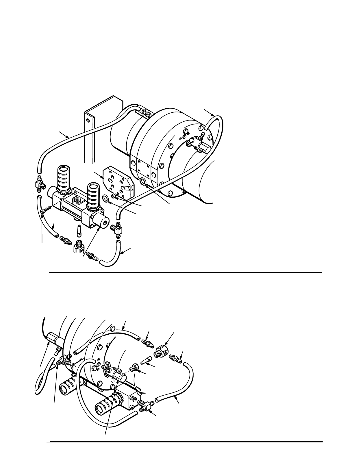
Parts
NOTE: This air valve can be
used with the pump’s
existing pilot valves.
Connect the tubes as
shown.
2
2
2
6
3
(part of item 1)
Lubricate
5
Lubricate
4
Torque to
27–45 in/lb
(3–5 N.m)
1
Air Valve Conversion Kit 222054
For Pump Models 218061, 218062,
218185 & 218079
Includes items 1 to 6
REF
NO. PART NO. DESCRIPTION QTY
1 220902 AIR VALVE ASSY. See pages
4 & 5 for parts & service
instructions 1
2 054138 TUBE, nylon 48 in.
3 104092 SCREW, cap, sch;
10–24 x 0.625 4
4 101888 SCREW, cap, sch
10–24 x 0.875 4
2
REF
NO. PART NO. DESCRIPTION QTY
5 107186 O–RING, buna–n2
6 183745 PLATE, adapter 1
6 307909
Page 7

Parts
5
2
7
Apply sealant
to threads
2
3
6
Press fit using
40–60 lbs force
5
1
4
Apply sealant
4
Apply sealant
1
Pilot Valve Conversion Kit 221152
For Pump Models 218060, 218061, 218062, 231019, 218185 & 218079
Includes items 1 to 7
REF
NO. PART NO. DESCRIPTION QTY
1 221133 PILOT VALVE ASSY.
See pages 6 & 7 for parts
& service instructions 2
2 108383 FITTING, seal, o–ring 2
3 159840 BUSHING; 1/4–18 npt(f)
x 1/8–27 npt(m) 1
REF
NO. PART NO. DESCRIPTION QTY
4 107191 TEE, barbed 2
5 054138 TUBE, polyurethane 48 in.
6 160736 FILTER, air 1
7 183620 HOUSING, filter, air 1
307909 7
Page 8

Air Control Valve 220902
Includes items 101 to 117
Parts
116
Apply sealant to threads
117
112
101
*110
115
Press fit
105
104
114*
108*
Lubricate
*109
Lubricate
Apply medium strength
sealant to threads.
Torque to 7–13 in/lb
(0.79–1.47 N.m)
103
*108
Lubricate
*106
Lubricate
Torque to
27–45 in/lb
(3–5 N.m)
111
*107
Lubricate
Air Control Valve 220902
Includes items 101 to 117
REF
NO. PART NO. DESCRIPTION QTY
101 183370 HOUSING, valve center 1
102 183369 HOUSING, valve end 2
103 183368 SPOOL, differential 2
104 183367 STEM, spool 1
105 183366 RETAINER, seal 2
106* 181464 GASKET, polyurethane 2
107* 110782 O–RING, buna–n2
108* 107186 O–RING, buna–n4
109* 108781 U–CUP, polyurethane 2
110* 108782 U–CUP, polyurethane 2
8 307909
REF
NO. PART NO. DESCRIPTION QTY
111 108780 SCREW, cap, hex hd;
112 100179 NUT, full hex; 10–24 UNC–2A 4
113 107191 TEE, barbed 2
114* 179861 TUBE, polyurethane; 0.25”
115 160736 FILTER, air 1
116 183620 HOUSING, air filter 1
117 108383 FITTING, barbed,
*Included in Repair Kit 220656 on page 5
102
Lubricate
113
Apply sealant
M5 x 0.8 x 150 4
(6.35 mm) O.D. 2
with buna–n o–ring 2
Page 9

Pilot Valve 221133
Includes items 201 to 210
Parts
210*
Lubricate
208
Torque to 27–45 in/lb
(3–5 N.m)
204
205*
Lubricate
201
207
202
Lubricate ID & OD
206
209*
203
Torque to 7.4–12.5 ft/lb
(10–17 N.m)
Pilot Valve 221133
Includes items 201 to 210
REF
NO. PART NO. DESCRIPTION QTY
201 183604 STEM, valve 1
202 183603 VALVE, air 1
203 183605 CAP, valve 1
204 183606 HOUSING, valve 1
205* 159589 O–RING, buna–n1
206 108961 SPRING, compression 1
REF
NO. PART NO. DESCRIPTION QTY
207 108960 SPRING, compression 1
208 108383 FITTING, barbed, buna–n o–ring
209* 156766 GASKET, copper 1
210* 107161 SEAL, pilot valve rod, buna–n1
*Included in Repair Kit 220656 on page 5.
seal;10–32 UNF–2A 1
307909 9
Page 10

Graco Standard Warranty
Graco warrants all equipment manufactured by Graco and bearing its name to be free from defects in material and workmanship on the
date of sale by an authorized Graco distributor to the original purchaser for use. With the exception of any special, extended, or limited
warranty published by Graco, Graco will, for a period of twelve months from the date of sale, repair or replace any part of the equipment
determined by Graco to be defective. This warranty applies only when the equipment is installed, operated and maintained in accordance with Graco’s written recommendations.
This warranty does not cover, and Graco shall not be liable for general wear and tear, or any malfunction, damage or wear caused by
faulty installation, misapplication, abrasion, corrosion, inadequate or improper maintenance, negligence, accident, tampering, or substitution of non–Graco component parts. Nor shall Graco be liable for malfunction, damage or wear caused by the incompatibility of
Graco equipment with structures, accessories, equipment or materials not supplied by Graco, or the improper design, manufacture,
installation, operation or maintenance of structures, accessories, equipment or materials not supplied by Graco.
This warranty is conditioned upon the prepaid return of the equipment claimed to be defective to an authorized Graco distributor for
verification of the claimed defect. If the claimed defect is verified, Graco will repair or replace free of charge any defective parts. The
equipment will be returned to the original purchaser transportation prepaid. If inspection of the equipment does not disclose any defect
in material or workmanship, repairs will be made at a reasonable charge, which charges may include the costs of parts, labor, and
transportation.
THIS WARRANTY IS EXCLUSIVE, AND IS IN LIEU OF ANY OTHER WARRANTIES, EXPRESS OR IMPLIED, INCLUDING BUT
NOT LIMITED TO WARRANTY OF MERCHANTABILITY OR WARRANTY OF FITNESS FOR A PARTICULAR PURPOSE.
Graco’s sole obligation and buyer’s sole remedy for any breach of warranty shall be as set forth above. The buyer agrees that no other
remedy (including, but not limited to, incidental or consequential damages for lost profits, lost sales, injury to person or property, or any
other incidental or consequential loss) shall be available. Any action for breach of warranty must be brought within two (2) years of the
date of sale.
Graco makes no warranty, and disclaims all implied warranties of merchantability and fitness for a particular purpose in connection
with accessories, equipment, materials or components sold but not manufactured by Graco. These items sold, but not manufactured
by Graco (such as electric motors, switches, hose, etc.), are subject to the warranty, if any, of their manufacturer. Graco will provide
purchaser with reasonable assistance in making any claim for breach of these warranties.
In no event will Graco be liable for indirect, incidental, special or consequential damages resulting from Graco supplying equipment
hereunder, or the furnishing, performance, or use of any products or other goods sold hereto, whether due to a breach of contract,
breach of warranty, the negligence of Graco, or otherwise.
FOR GRACO CANADA CUSTOMERS
The parties acknowledge that they have required that the present document, as well as all documents, notices and legal proceedings
entered into, given or instituted pursuant hereto or relating directly or indirectly hereto, be drawn up in English. Les parties reconnaissent avoir convenu que la rédaction du présente document sera en Anglais, ainsi que tous documents, avis et procédures judiciaires
exécutés, donnés ou intentés à la suite de ou en rapport, directement ou indirectement, avec les procedures concernées.
Graco Information
TO PLACE AN ORDER, contact your Graco distributor, or call one of the following numbers
to identify the distributor closest to you:
1–800–367–4023 Toll Free
612–623–6921
612–378–3505 Fax
All written and visual data contained in this document reflects the latest product information available at the time of publication.
Graco reserves the right to make changes at any time without notice.
International Offices: Belgium, Korea, Hong Kong, Japan
Sales Offices: Minneapolis, Detroit
www.graco.com
PRINTED IN USA 307909 04/1988, Revised 08/2002
10 307909
 Loading...