

Page 1
Instructions–Parts List
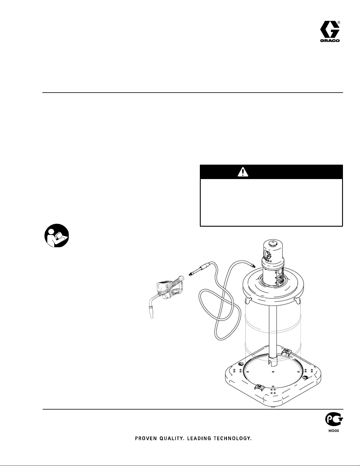
3:1 Fireball 225 or 5:1 Fireball
300 Portable Gear Lube Pump
For dispensing fluid in stationary or mobile installations. For professional use
only.
Model 246903 – 3:1 Fireball 225 Pump
540 psi (3.7 MPa, 37 bar) Maximum Working Pressure
Model 225728 – 5:1 Fireball 300 Pump
900 psi (6.2 MPa, 62 bar) Maximum Working Pressure
Includes dispense kit, roll-around base, and
drum cover
This system is designed to be used only in pumping non-corrosive and non-abrasive lubricants.
Any other use of the system can cause unsafe
operating conditions and result in component rupture, fire, or explosion, which can cause serious
bodily injury, including fluid injection.
Important Safety Instructions
Read all warnings and instructions in this manual.
Save these instructions.
WARNING
ENG
307884S
Page 2

Warnings
WARNINGWARNING
EQUIPMENT MISUSE HAZARD
Equipment misuse can cause the equipment to rupture or malfunction and result in serious injury.
D This equipment is for professional use only.
D Read all instruction manuals, tags, and labels before operating the equipment.
D Use the equipment only for its intended purpose. If you are not sure, call your Graco distributor.
D Do not alter or modify this equipment. Use only genuine Graco parts and accessories.
D Check equipment daily. Repair or replace worn or damaged parts immediately.
D Do not exceed the maximum working pressure stated on the equipment or in the Technical Data
section for your equipment. Do not exceed the maximum working pressure of the lowest rated
component in your system.
D Use fluids and solvents that are compatible with the equipment wetted parts. Refer to the Tech-
nical Data section of all equipment manuals. Read the fluid and solvent manufacturer’s warn-
ings.
D Handle hoses carefully. Do not pull on hoses to move equipment.
D All fluid hoses must have spring guards on both ends. The spring guards help protect the
hose from kinks or bends at or close to the coupling, which can result in hose rupture.
D Route hoses away from traffic areas, sharp edges, moving parts, and hot surfaces. Do not
expose Graco hoses to temperatures above 82_C (180_F) or below –40_C (–40_F).
D Do not lift pressurized equipment.
D Comply with all applicable local, state, and national fire, electrical, and safety regulations.
D Be sure you know the maximum working pressure of the flexible nozzle you are using. Never
use a flexible nozzle designed for low pressure dispensing valves or hand-powered lubricating
equipment on a high pressure dispensing valve.
D Do not modify any part of the dispensing valve; doing so could cause a malfunction and result in
serious bodily injury. Be sure the dispensing valve has a maximum working pressure that meets
or exceeds that of the pump.
D The maximum fluid working pressure of these pumps, when operated at a maximum of 180 psi
(1.2 MPa, 12 bar) air pressure is 900 psi (6.2 MPa, 62 bar).
2 307884
Page 3
WARNING
WARNING
INJECTION HAZARD
High pressure fluid from dispense device, hose leaks or ruptured components will pierce skin. This
may look like just a cut, but it is a serious injury that can result in amputation. Get immediate
surgical treatment.
D Do not point the dispensing device at anyone or at any part of the body.
D Do not put your hand or fingers over the fluid outlet.
D Do not stop or deflect leaks with your hand, body, glove, or rag.
D Follow Pressure Relief Procedure in this manual, when you stop dispensing and before clean-
ing, checking or servicing equipment.
D Tighten all fluid connections before operating the equipment.
D Check the hoses, tubes, and couplings daily. Replace worn or damaged parts immediately.
HAZARDOUS FLUIDS
Improper handling of hazardous fluids or inhaling toxic fumes can cause extremely serious injury or
death due to splashing in the eyes, ingestion, or bodily contamination.
D Know the specific hazards of the fluid you are using.
D Store hazardous fluid in an approved container. Dispose of hazardous fluid according to all local,
state, and national guidelines.
D Always wear protective eyewear, gloves, clothing, and respirator as recommended by the fluid
and solvent manufacturer.
FIRE AND EXPLOSION HAZARD
Improper grounding, poor ventilation, open flames, or sparks can cause a hazardous condition and
result in a fire or explosion and serious injury.
D Ground the equipment. Refer to Grounding below.
D If there is any static sparking or you feel an electric shock while using this equipment, stop
dispensing immediately. Do not use the equipment until you identify and correct the problem.
D Provide fresh air ventilation to avoid the buildup of flammable fumes from solvents or the fluid
being dispensed.
D Do not smoke in the dispensing area.
3307884
Page 4
WARNINGWARNING
MOVING PARTS HAZARD
Moving parts can pinch or amputate your fingers.
D Keep clear of all moving parts when starting or operating the pump.
D Before servicing the equipment, follow the Pressure Relief Procedure on page 8 to prevent the
equipment from starting unexpectedly.
United States Government safety standards have been adopted under the Occupational Safety and Health Act.
You should consult these standards––particularly General Standards, Part 1910, and Construction Standards, Part
1926.
Installation
Grounding
To reduce the risk of static sparking, ground the pump.
Check your local electrical code for detailed grounding
instructions for your area and type of equipment.
D Pump: Use ground wire and clamp as shown in
Fig. 1.
D Air and fluid hoses: Use only grounded hoses.
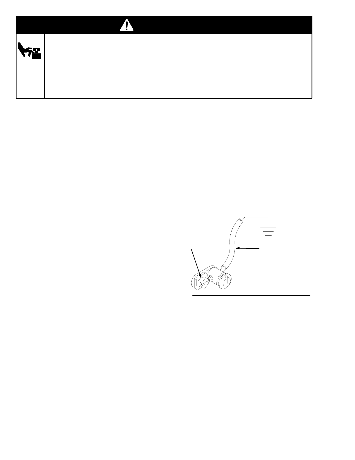
To ground the pump, remove ground screw (Z)
and insert through the eye of the ring terminal at
end of ground wire (Y). Fasten ground screw
back onto pump and tighten securely. Connect
the other end of ground wire to a true earth
ground. See Fig. 1. To order a ground wire and
clamp, order Part No. 222011.
D Air compressor: Follow manufacturer’s
recommendations.
D Dispensing valve: Obtain grounding through
connection to a properly grounded fluid hose and
pump.
D Fluid supply container: Follow your local code.
D Object being lubricated: Follow your local code.
D Any pails used when flushing: Use only metal,
grounded pails when flushing. Make firm
metal-to-metal contact between a metal part of the
dispensing valve and the pail. Use the lowest
possible pressure.
D To maintain grounding continuity when flushing or
relieving pressure, always hold a metal part of the
dispensing valve firmly to the side of a metal pail,
and then open the dispensing valve.
Fig. 1
Z
Y
TI1052
4 307884
Page 5

Installation
The typical installation shown in Fig. 2 is only an installation guide; it is not an actual system design. Contact your
Graco distributor for assistance in designing a system to suit your needs.
D
G
C
B
A
E
K
KEY
A Fluid dispense line
B Pump ground wire
C Air regulator
D Main air supply line
E Air filter
F Pump lubricator
G Pump runaway valve
H Meter
K Bleed-type master air valve
Fig. 2
See Parts Drawing on page 10
Place an open 16-gallon (60-liter) steel drum (J) on
the base (3).
Secure the drum with the hold down clamps (3c)
and hex head bolts (3c).
Place the drum cover (4) on the drum, and fasten
it with the screws and washers provided. Carefully
guide the pump riser tube through the mounting
gasket. Refer to the assembled view of Model
225728 on the front cover.
F
H
04044B
5307884
Page 6

Air and Fluid Line Accessories
Installation
NOTE: Install the accessories in the order shown in
Fig. 2 on page 5.
CAUTION
Do not hang the air accessories directly on the air
inlet. Mount them on brackets. The fittings are
not strong enough to support the accessories and
may break.
D Install a bleed-type master air valve (K) upstream
from the pump air regulator (C), but within easy
reach of the pump.
To order a 300 psi (2.1 MPa, 21 bar) maximum
working pressure, 1/2 in. npt bleed-type master air
valve, order Part No. 107142.
WARNING
A bleed-type master air valve is required in the
system to help reduce the risk of serious bodily
injury, including fluid injection, splashing in the
eyes, and injury from moving parts when
adjusting or repairing the pump. This valve
relieves air trapped between the valve and the
pump to prevent the pump from cycling unexpectedly.
D Install an air line lubricator (F) for automatic air
motor lubrication.
To order a 250 psi (1.74 MPa, 17.4 bar) maximum
working pressure air line lubricator, order a Part No.
below:
3/8 in. npt 214847
1/2 in. npt 214848
D Install an air regulator (C) to control pump speed
and pressure.
To order a 300 psi (2.1 MPa, 21 bar) maximum
working pressure regulator, order a Part No. below:
3/8 in. npt 109075
1/2 in. npt 244844
D Install an air line filter (E) to remove harmful dirt
and contaminants from your compressed air supply.
To order a 250 psi (1.74 MPa, 17.4 bar) maximum
working pressure air filter, order a Part No. below:
3/8 in. npt 106148
1/2 in. npt 214849
D Install a pump runaway valve (G) to shut off the air
to the pump if the pump accelerates beyond the
pre-adjusted setting. A pump that runs too fast can
be seriously damaged.
To order a pump runaway valve, order Part No.
224040.
6 307884
Page 7

Installation
Dispense Kit (Parts 2a and 2b)
Connect the hose (2a) to the pump outlet.
Connect the dispense valve (2b) to the hose (2a).
Air Regulator Kit (Parts 5a – 5d)
KEY
2a Fluid hose
2b Dispense valve
5a Regulator, air, 3/8 npt (f) 0–250 psi (17.4 bar)
5b Gauge, air pressure
5c Valve, air bleed–type 3/8 npt (f)
5d Nipple, 3/8 npt
2a
5a
5d
2b
5b
5c
5d
Fig. 3
7307884
Page 8

Operation
Pressure Relief Procedure
WARNING
INJECTION HAZARD
To reduce the risk of serious bodily
injury, including fluid injection, injury from
moving parts, or splashing in the eyes or
on the skin, always follow this procedure whenever
you shut off the pump, when checking or servicing
any part of the system, when installing or changing
dispensing devices, and whenever you stop dispensing.
1. Close the pump air regulator.
2. Close the pump’s bleed-type master air valve
(required in the system).
3. Hold a metal part of the gun or valve firmly to a
grounded metal waste container and trigger to
relieve the fluid pressure.
If you suspect that the dispensing valve is clogged, or
that pressure has not been fully relieved after following
the steps above, very slowly loosen the dispensing
valve coupler or hose end coupling to relieve pressure
gradually, then loosen completely. Then clear the clog.
8 307884
Page 9

Operation
Startup
WARNING
The maximum working pressure of each pump in
your system may not be the same. To reduce the
risk of overpressurizing any part of your system, be
sure you know the maximum working pressure rating of each pump and its connected components.
Never exceed the maximum working pressure of
the lowest rated component connected to a particular pump.
To determine the fluid output pressure using the air
regulator reading, multiply the ratio of the pump by
the air pressure shown on the regulator gauge. For
example:
5:(1) ratio x 100 psi air = 500 psi fluid output
4. Set the air pressure to each pump at the lowest
pressure needed to get the desired results. Use
the regulator to adjust pump speed and pressure.
CAUTION
Never allow the pump to run dry of the fluid
being pumped. A dry pump quickly accelerates
to a high speed and could possibly damage
itself. If the pump accelerates quickly, stop it
immediately, and check the fluid supply. If the
supply container is empty and air has been
pumped into the lines, prime the pump and lines
with fluid, or flush it and leave it filled with a
compatible solvent. Be sure to eliminate all air
from the fluid system.
[5:(1) ratio x 0.7 MPa ( 7 bar) air =
3.5 MPa (35 bar) fluid output]
Limit the air to the pump so that no air line or fluid
line component or accessory is over-pressurized.
1. Open the master air valve from the compressor.
2. Trigger the dispensing valve into a grounded metal
waste container, making firm metal-to-metal
contact between the container and valve.
3. Open the bleed-type master air valve, and open
the pump air regulator slowly, just until the pump is
running. When the pump is primed and all air has
been pushed out of the lines, release the trigger.
NOTE: When the pump is primed, and with sufficient
air supplied, the pump starts when the dispensing
valve is opened and shuts off when it is closed.
NOTE: A pump runaway valve can be installed on the
air line to automatically shut off the pump if it starts to
run too fast. See Air and Fluid Line Accessories on
page 6.
5. Read and follow the instructions supplied with
each component in your system.
6. To shut off the system, always relieve the
pressure.
WARNING
INJECTION HAZARD
To reduce the risk of serious injury
whenever you are instructed to relieve
pressure, always follow the Pressure
Relief Procedure at left.
9307884
Page 10

Parts Drawing
Model 246903
3:1 Ratio Fire-Ball 225 Portable Gear Lube Pump
with Drum Cover
Model 225728
5:1 Ratio Fire-Ball 300 Portable Gear Lube Pump
with Drum Cover
2
Dispense Kit
includes items
2a and 2b
2a
5
1
Dispense Kit
includes items
5a – 5d
(5d not shown)
2b
5b
5a
5c
4
J
3
10 307884
Page 11

Parts Lists
Model 246903
3:1 Ratio Fire-Ball 225 Portable Gear Lube Pump
with Drum Cover
Model 225728
5:1 Ratio Fire-Ball 300 Portable Gear Lube Pump
with Drum Cover
Ref.
No. Part No. Description Qty.
1 248097 PUMP, 3:1 Ratio Fire-ball; used
on model 245903
See manual 309868 for parts. 1
203872 PUMP, 5:1 Ratio Fire-ball; used
on model 225728
See manual 306518 for parts. 1
2 237075 KIT, DISPENSE;
Includes items 101 and 102.
See separate Parts List at right. 1
3 203622 PORTABLE BASE
See manual 308668 for parts.
4 204574 DRUM COVER
See manual 306345 for parts. 1
5 224512 KIT, AIR REGULATOR
See manual parts list. 1
Ref. No. 2
Dispense Kit 237075, Series B
Ref.
No. Part No. Description Qty.
2a 220591 HOSE, fluid; 1/2” ID; cpld
1/2 x 1/2 npt(mbe); 72” 1
2b 255349 DISPENSING VALVE;
See manual 312865 for parts. 1
Ref. No. 5
Air Regulator Kit 224512
Ref.
No. Part No. Description Qty.
5a 110234 REGULATOR, air; 3/8 npt(f); 1
0–250 psi
(0–1.7 MPa, 0–17.4 bar) range;
see manual 308167
5b 100960 GAUGE, air pressure 1
5c 110224 VALVE, air, bleed-type; 3/8 npt(f) 1
5d 156849 NIPPLE; 3/8 npt 2
11307884
Page 12

Graco Standard Warranty
Graco warrants all equipment manufactured by Graco and bearing its name to be free from defects in material and workmanship on the
date of sale by an authorized Graco distributor to the original purchaser for use. With the exception of any special, extended, or limited
warranty published by Graco, Graco will, for a period of twelve months from the date of sale, repair or replace any part of the equipment
determined by Graco to be defective. This warranty applies only when the equipment is installed, operated and maintained in
accordance with Graco’s written recommendations.
This warranty does not cover, and Graco shall not be liable for general wear and tear, or any malfunction, damage or wear caused by
faulty installation, misapplication, abrasion, corrosion, inadequate or improper maintenance, negligence, accident, tampering, or
substitution of non–Graco component parts. Nor shall Graco be liable for malfunction, damage or wear caused by the incompatibility of
Graco equipment with structures, accessories, equipment or materials not supplied by Graco, or the improper design, manufacture,
installation, operation or maintenance of structures, accessories, equipment or materials not supplied by Graco.
This warranty is conditioned upon the prepaid return of the equipment claimed to be defective to an authorized Graco distributor for
verification of the claimed defect. If the claimed defect is verified, Graco will repair or replace free of charge any defective parts. The
equipment will be returned to the original purchaser transportation prepaid. If inspection of the equipment does not disclose any defect
in material or workmanship, repairs will be made at a reasonable charge, which charges may include the costs of parts, labor, and
transportation.
THIS WARRANTY IS EXCLUSIVE, AND IS IN LIEU OF ANY OTHER WARRANTIES, EXPRESS OR IMPLIED, INCLUDING BUT
NOT LIMITED TO WARRANTY OF MERCHANTABILITY OR WARRANTY OF FITNESS FOR A PARTICULAR PURPOSE.
Graco’s sole obligation and buyer’s sole remedy for any breach of warranty shall be as set forth above. The buyer agrees that no other
remedy (including, but not limited to, incidental or consequential damages for lost profits, lost sales, injury to person or property, or any
other incidental or consequential loss) shall be available. Any action for breach of warranty must be brought within two (2) years of the
date of sale.
Graco makes no warranty, and disclaims all implied warranties of merchantability and fitness for a particular purpose in connection
with accessories, equipment, materials or components sold but not manufactured by Graco. These items sold, but not manufactured
by Graco (such as electric motors, switches, hose, etc.), are subject to the warranty, if any, of their manufacturer. Graco will provide
purchaser with reasonable assistance in making any claim for breach of these warranties.
In no event will Graco be liable for indirect, incidental, special or consequential damages resulting from Graco supplying equipment
hereunder, or the furnishing, performance, or use of any products or other goods sold hereto, whether due to a breach of contract,
breach of warranty, the negligence of Graco, or otherwise.
FOR GRACO CANADA CUSTOMERS
The parties acknowledge that they have required that the present document, as well as all documents, notices and legal proceedings
entered into, given or instituted pursuant hereto or relating directly or indirectly hereto, be drawn up in English. Les parties
reconnaissent avoir convenu que la rédaction du présente document sera en Anglais, ainsi que tous documents, avis et procédures
judiciaires exécutés, donnés ou intentés à la suite de ou en rapport, directement ou indirectement, avec les procedures concernées.
Graco Information
For the latest information about Graco products, visit www.graco.com.
TO PLACE AN ORDER, contact your Graco distributor or call to identify the distributor closest to you:
Phone: 612–623–6928 or Toll Free: 1–800–533–9655 Fax: 612–378–3590
All written and visual data contained in this document reflects the latest product information available at the time of publication.
Graco reserves the right to make changes at any time without notice.
12 307884
Original instructions. This manual contains English. MM 307884
Graco Headquarters: Minneapolis
International Offices: Belgium, China, Japan, Korea
GRACO INC. P.O. BOX 1441 MINNEAPOLIS, MN 55440–1441
Copyright 1988, Graco Inc. is registered to ISO 9001
www.graco.com
Revised 06/2010
 Loading...