

Page 1
Instructions–Parts List
FireballR Pumps
For dispensing fluid in stationary or mobile installations. For
professional use only.
Important Safety Instructions
Read all warnings and instructions in this manual.
Save these instructions.
3:1 Fireball 225 Pump – 540 psi (37 bar) Maximum Working Pressure
307883G
ENG
Model No. Size Type* Hose
Kit
246904 16-gallon open drum S X X X
246906 55-gallon open drum
246907 55-gallon closed drum or 275 gallon
obround tank
S
S
X
X
Cover Bung
Adapter
X X
5:1 Fireball 300 Pump – 900 psi (62 bar) Maximum Working Pressure
Model No. Size Type* Hose
Kit
225094 16-gallon open drum
222086 16-gallon open drum, truck mounted
225642 55-gallon open drum
225640 55-gallon closed drum
206655 55-gallon closed drum, truck mounted
204264 55-gallon closed drum, truck mounted
225931 275-gallon obround tank S X X
M
M
M
S
S
S
X
X
X
X
X
X
Cover Bung
Adapter
X
X X
X
X
Sturdi
Clamp
X
Sturdi
Clamp
X
X X
Hold-
Down Kit
Hold-
Down Kit
X
X
10:1 Fireball 425 Pump – 1800 psi (120 bar) Maximum Working Pressure
Model No. Size Type* Hose
Kit
225782 55-gallon open drum S X X
225786 55-gallon closed drum
206656 55-gallon closed drum, truck mounted
222067 55-gallon closed drum, truck mounted
M
M
S
X
X
X
Cover Bung
Adapter
X
X
X X
Sturdi
Clamp
Hold-
Down Kit
X
X
Page 2

WARNINGS
WARNINGWARNING
EQUIPMENT MISUSE HAZARD
Equipment misuse can cause the equipment to rupture or malfunction and result in serious injury.
D This equipment is for professional use only.
D Read all instruction manuals, tags, and labels before operating the equipment.
D Use the equipment only for its intended purpose. If you are not sure, call your Graco distributor.
D Do not alter or modify this equipment.
D Check equipment daily. Repair or replace worn or damaged parts immediately.
D Do not exceed the maximum working pressure stated on the equipment or in the Technical Data
for your equipment. Do not exceed the maximum working pressure of the lowest rated component in your system.
D Use fluids and solvents that are compatible with the equipment wetted parts. Refer to the Tech-
nical Data section of all equipment manuals. Read the fluid and solvent manufacturer’s warn-
ings.
D Handle hoses carefully. Do not pull on hoses to move equipment.
D All fluid hoses must have spring guards on both ends. The spring guards help protect the
hose from kinks or bends at or close to the coupling, which can result in hose rupture.
D Route hoses away from traffic areas, sharp edges, moving parts, and hot surfaces. Do not
expose Graco hoses to temperatures above 82_C (180_F) or below –40_C (–40_F).
D Do not lift pressurized equipment.
D Comply with all applicable local, state, and national fire, electrical, and safety regulations.
D Use only dispensing valves that are designed to dispense motor oil. Do not modify any part of
the dispensing valve; doing so could cause a malfunction and result in serious bodily injury. Be
sure the dispensing valve has a maximum working pressure that meets or exceeds that of the
pump.
3078832
Page 3
WARNING
WARNING
INJECTION HAZARD
High pressure fluid from dispense device, hose leaks or ruptured components will pierce skin. This
may look like just a cut, but it is a serious injury that can result in amputation. Get immediate
surgical treatment.
D Do not point the dispensing device at anyone or at any part of the body.
D Do not put your hand or fingers over the fluid outlet.
D Do not stop or deflect leaks with your hand, body, glove, or rag.
D Follow Pressure Relief Procedure in this manual, when you stop dispensing and before clean-
ing, checking or servicing equipment.
D Tighten all fluid connections before operating the equipment.
D Check the hoses, tubes, and couplings daily. Replace worn or damaged parts immediately.
HAZARDOUS FLUIDS
Improper handling of hazardous fluids or inhaling toxic fumes can cause extremely serious injury or
death due to splashing in the eyes, ingestion, or bodily contamination.
D Know the specific hazards of the fluid you are using.
D Store hazardous fluid in an approved container. Dispose of hazardous fluid according to all local,
state, and national guidelines.
D Always wear protective eyewear, gloves, clothing, and respirator as recommended by the fluid
and solvent manufacturer.
FIRE AND EXPLOSION HAZARD
Improper grounding, poor ventilation, open flames, or sparks can cause a hazardous condition and
result in a fire or explosion and serious injury.
D Ground the equipment. Refer to Grounding below.
D If there is any static sparking or you feel an electric shock while using this equipment, stop
dispensing immediately. Do not use the equipment until you identify and correct the problem.
D Provide fresh air ventilation to avoid the buildup of flammable fumes from solvents or the fluid
being dispensed.
D Do not smoke in the dispensing area.
3307883
Page 4
WARNINGWARNING
MOVING PARTS HAZARD
Moving parts can pinch or amputate your fingers.
D Keep clear of all moving parts when starting or operating the pump.
D Before servicing the equipment, follow the Pressure Relief Procedure on page 9 to prevent the
equipment from starting unexpectedly.
United States Government safety standards have been adopted under the Occupational Safety and Health Act.
You should consult these standards––particularly General Standards, Part 1910, and Construction Standards, Part
1926.
Installation
Grounding
To reduce the risk of static sparking, ground the pump.
Check your local electrical code for detailed grounding
instructions for your area and type of equipment.
D Pump: Use ground wire and clamp as shown in
Fig. 1.
D Air and fluid hoses: Use only electrically conductive
hoses.
D Air compressor: Follow manufacturer’s recommen-
dations.
D Dispensing valve: Obtain grounding through con-
nection to a properly grounded fluid hose and
pump.
D Fluid supply container: Follow your local code.
D Object being lubricated: Follow your local code.
D Any pails used when flushing: Use only metal,
grounded pails when flushing. Make firm metal-tometal contact between a metal part of the dispensing valve and the pail. Use the lowest possible
pressure.
D To maintain grounding continuity when flushing or
relieving pressure, always hold a metal part of the
dispensing valve firmly to the side of a metal pail,
and then open the dispensing valve.
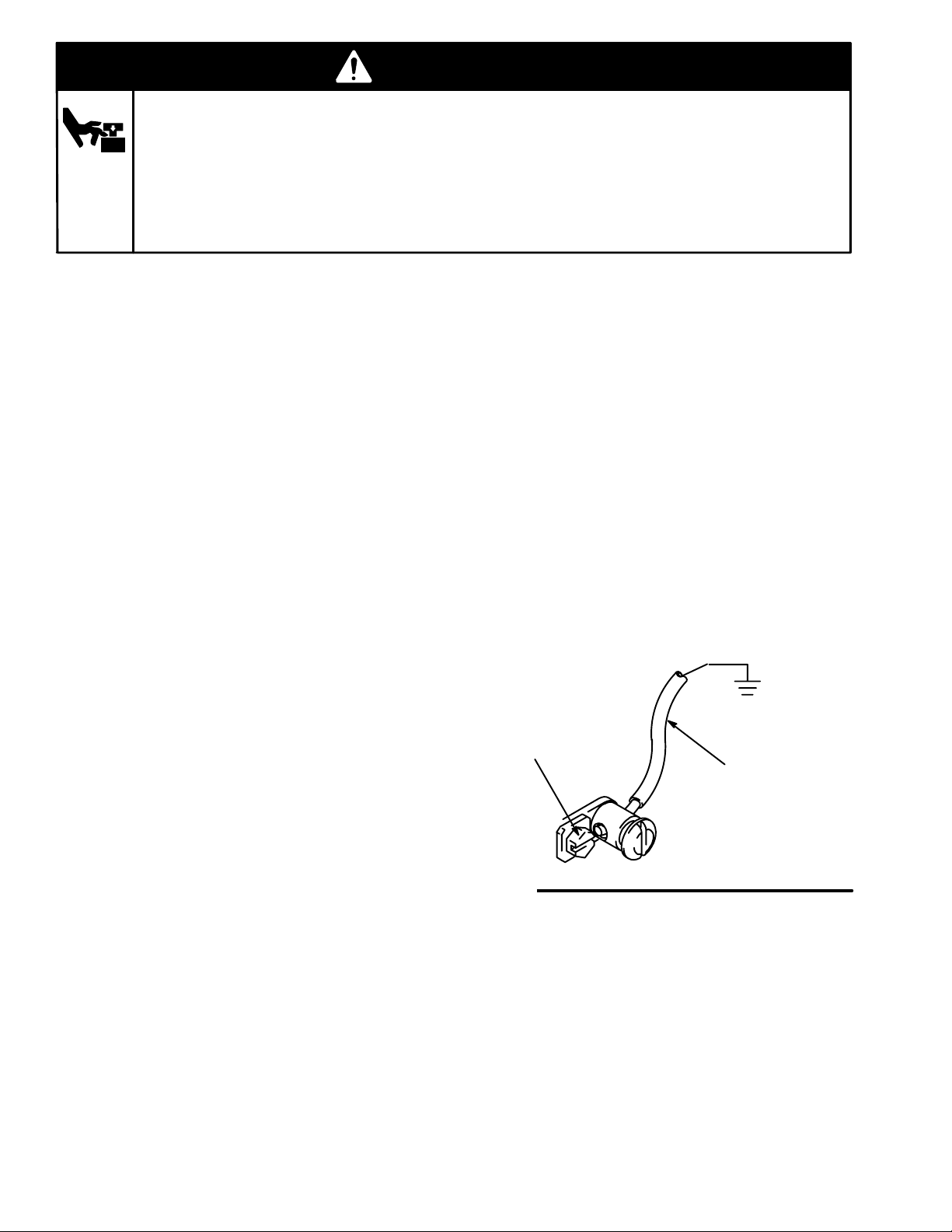
To ground the pump, remove ground screw (Z)
and insert through the eye of the ring terminal at
end of ground wire (Y). Fasten ground screw
back onto pump and tighten securely. Connect
other end of ground wire to a true earth ground.
See Fig. 1. To order a ground wire and clamp,
order Part No. 222011.
Z
Y
Fig. 1
04630
3078834
Page 5
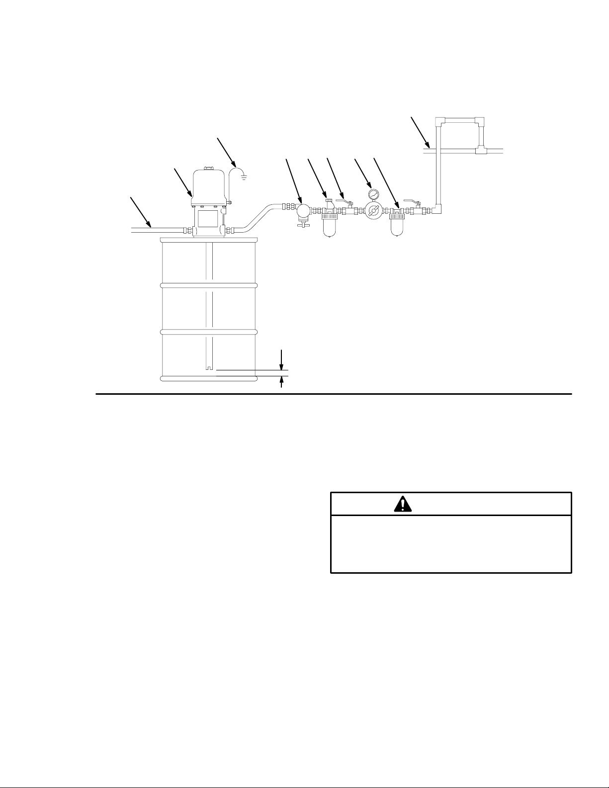
Installation–Stationary Mounting
The typical installation shown in Fig. 2 is only an installation guide; it is not an actual system design. Contact your
Graco distributor for assistance in designing a system to suit your needs.
For Stationary Mountings
B
A
Fig. 2
J
C
DEFGH
A Fluid outlet line
B Pump
C Ground wire
D Pump runaway valve
E Air lubricator
F Bleed-type master air valve
1/2 in. (13 mm)
G Air regulator
H Air filter
J Main air line
01611
NOTE: See Fig. 4 on page 7 for the mobile mounting
installation.
Stationary Mounting Layout
Plan the mounting layout for easy operator access to
the pump air controls, sufficient room to change
drums, and a secure mounting platform.
For ease in changing drums, install a pump elevator.
Open-Drum, Cover-Mounted Pumps
1. Remove the original drum cover.
2. Mount and fasten the new drum cover.
3. Guide the pump riser tube through the mounting
gasket.
Closed Bung-Type Drum
1. Loosen the drum cover vent plug, and remove the
bung cover.
Air and Fluid Line Accessories
Install the accessories in the order shown in Fig. 2.
CAUTION
Do not hang the air accessories directly on the air
inlet. Mount them on brackets. The fittings are not
strong enough to support the accessories and may
break.
D Use thread sealant on male threads except at
swivel connections.
D Install a pump runaway valve (D) to stop the pump
if the fluid supply is depleted.
D Install a bleed-type master air valve (F) upstream
from the pump air regulator (G), but within easy
reach of the pump.
2. Install the pump through the bung hole until the
pump foot valve is 1/2 in. (13 mm) off the drum
bottom. Tighten the bung adapter.
To order a 300 psi (21 bar) maximum working
pressure, 1/2 in. npt bleed-type master air valve,
order Part No. 107142.
5307883
Page 6

Installation–Stationary Mounting
D Install a thermal relief kit on the dispensing valve
side of the pump to assist in relieving pressure in
WARNING
the pump, hose, and dispensing valve due to heat
expansion.
A bleed-type master air valve is required in the
system to help reduce the risk of serious bodily
injury, including fluid injection, splashing in the
eyes, and injury from moving parts when
adjusting or repairing the pump. This valve
relieves air trapped between the valve and the
pump to prevent the pump from cycling unexpectedly.
D Install an air line lubricator (E) for automatic air
motor lubrication.
To order a 250 psi (17.5 bar) maximum working
pressure air line lubricator, order a Part No. below:
3/8 in. npt 214847
1/2 in. npt 214848
D Install an air regulator (G) to control pump speed
and pressure.
To order a 300 psi (21 bar) maximum working
pressure regulator, order a Part No. below:
3/8 in. npt 109075
1/2 in. npt 244844
To order an alternate relief kit for the 3:1 Fireball
225 pumps – 540 psi (37 bar) order Part No.
235998.
To order a thermal relief kit for the 5:1 Fire-Ball
pump—900 psi (62 bar) maximum working pressure—order Part No. 237893.
To order a thermal relief kit for the 10:1 Fireball 425
pump—1600 psi (110 bar) maximum working
pressure—order Part No. 240429.
Hose Kits
Assemble hose kits as shown in Fig. 3.
103
AIR
101
102
FLUID
104
D Install an air line filter (H) to remove harmful dirt
and contaminants from your compressed air supply.
To order a 250 psi (17.5 bar) maximum working
pressure air filter, order a Part No. below:
3/8 in. npt 106148
1/2 in. npt 214849
Fig. 3
3078836
Page 7

Installation–Mobile Mounting
The typical installation shown in Fig. 4 is only an installation guide; it is not an actual system design. Contact your
Graco distributor for assistance in designing a system to suit your needs.
For Mobile Mountings
K Hose reel
L Truck bed
M Hold-down rods
N Compressor
P Ground wires
Fig. 4
See Air and Fluid
Line Accessories
on page 5
N
M
L
K
P
01612
Mobile Mounting Layout
Plan the layout for easy operator access to the pump
air controls, sufficient room to change drums, and a
secure mounting platform.
Drum Mounting
1. Place the drum in the desired location.
2. Place the hold-down lugs (V) or drum locators (U)
around the drum base and bolt directly to the truck
bed or mounting platform. See Fig. 5.
Open-Drum, Cover-Mounted Pumps
1. Remove the original drum cover.
2. Mount the new drum cover and fasten.
3. Guide the pump riser tube through the mounting
gasket.
4. Align the drum cover eyelets (Q) with the holddown rods (T), install the cover brackets (S) and
wing nuts (R) and tighten securely. See Fig. 5.
Q
Q Drum cover eyelets
R Wing nuts
S Hold-down brackets
T Hold-down rods
U Drum locators
V Hold-down rod lugs
Fig. 5
R
S
T
U
V
01613
7307883
Page 8

Installation–Mobile Mounting
Closed Bung-Type-Drum, Cover-Mounted
Pump
1. Insert the pump riser tube through the gasket (W)
and drum cover (X). Fasten the Fire-Ball pump
from the top side and the Fireball pump from the
bottom side. See Fig. 6.
2. Slide the rubber grommet (Y), tapered end down,
onto the riser tube and push it up against the pump
base. See Fig. 6.
3. Guide the pump riser tube through the drum bung
hole (Z) and place the cover on the drum. See
Fig. 6.
4. Align the drum cover eyelets (Q) with the holddown rods (T), install the cover brackets (S) and
wing nuts (R) and tighten securely. See Fig. 5.
Closed Bung-Type-Drum,
Sturdi-Clamp-Mounted Pumps
1. Remove the adjustable bung adapter from the
pump riser tube.
2. Screw the bung adapter (EE) into the bung hole.
W Gasket
X Drum cover
Y Grommet
Z Bung hole
Fig. 6
W
X
Y
Z
01614
3. Loosen the wing nuts (BB) and slide the clamp
(AA) onto the pump riser tube, up to the base. See
Fig. 7.
4. Holding the clamp onto the pump, insert the pump
riser tube through the bung adapter, and lower the
pump until the clamp rests on the edge of the
drum. See Fig. 7.
5. Install the sturdi-clamp so its upper jaw fits against
the pump base projection, its u-bolt (DD) fits
around the riser tube, and its lower jaw fits against
the bung adapter. Tighten the wing nuts (BB). See
Fig. 7.
6. Tighten the T-handle (CC) firmly to the side of the
drum.
3078838
AA Clamp
BB Wing nuts
CC T-handle
DD U-bolt
EE Bung adapter
Fig. 7
AA
BB
CC
DD
EE
01615
Page 9

Operation
Pressure Relief Procedure
WARNING
INJECTION HAZARD
To reduce the risk of serious bodily
injury, including fluid injection, injury from
moving parts, or splashing in the eyes or
on the skin, always follow this procedure whenever
you shut off the pump, when checking or servicing
any part of the system, when installing or changing
dispensing devices, and whenever you stop dispensing.
1. Close the air regulator and disconnect the air supply hose.
2. Close the pump’s bleed-type master air valve (required in the system).
3. Open the dispensing valve until pressure is fully
relieved.
If you suspect that the dispensing valve is clogged, or
that pressure has not been fully relieved after following
the steps above, very slowly loosen the dispensing
valve coupler or hose end coupling to relieve pressure
gradually, then loosen completely.
Operating
3. For the pump that is connected, trigger the
dispensing valve into a grounded metal waste
container, making firm metal-to-metal contact
between the container and valve. Open the bleedtype master air valve and open the pump air
regulator slowly, just until the pump is running.
When the pump is primed and all air has been
pushed out of the lines, release the trigger.
4. If you have more than one pump, repeat this
procedure for each pump.
5. When the pump is primed and has sufficient air
supplied to it, it starts when the dispensing valve is
opened and shuts off when it is closed.
CAUTION
Never allow the pump to run dry of the fluid
being pumped. A dry pump will quickly
accelerate to a high speed and possibly damage
itself. If the pump accelerates quickly, stop it
immediately, and check the fluid supply. If the
supply container is empty and air has been
pumped into the lines, prime the pump and lines
with fluid, or flush it and leave it filled with a
compatible solvent. Be sure to eliminate all air
from the fluid system.
WARNING
Never exceed 180 psi (12.6 bar) Maximum Air
Pressure to these pumps. Using higher air
pressure will cause the pump to over pressurize
which may result in component rupture, fire, or
explosion and cause serious bodily injury.
NOTE: Read and follow the warnings and instructions
in the manual for each of the system components.
1. Close the air regulators and bleed-type master air
valves to all but one pump.
2. Open the master air valve from the compressor.
6. Set the air pressure to each pump at the lowest
pressure needed to get adequate fluid delivery.
7. When shutting off the system, and before checking
or servicing it, relieve the pressure.
WARNING
INJECTION HAZARD
To reduce the risk of serious injury
whenever you are instructed to relieve
pressure, always follow the Pressure
Relief Procedure at left.
9307883
Page 10

3:1 Fire-Ball 225 Parts Lists and Drawings
Model 222063
Hose Kit for Fire-Ball 225 Pump
Ref
No. Part No. Description Qty.
101 203320 AIR HOSE, 3/8” ID, cpld
3/8–14 npt (mbe), 72” (1.8 m) 1
102 220591 FLUID HOSE, 1/2” ID, cpld
1/2–14 npt(mbe), 72” (1.8 m) 1
103 155494 UNION, 90_, 3/8–14 npt(m) x
3/8 npsm(f) swivel 1
104 155470 UNION, 90_, 1/2–14 npt(m) x
1/2 npsm(f) swivel 1
Model 246904
3:1 Ratio Fire-Ball 225, 16-Gallon Open Drum
Ref
No. Part No. Description Qty.
1 248097 5:1 FIRE-BALL PUMP
See manual 309868 for parts. 1
2 222063 HOSE & FITTING KIT
See parts list above. 1
3 204574 DRUM COVER 1
224512 AIR REGULATOR KIT (not shown)1
104
102
10
103
2
1
101
3
01616
9
8
Model 246702
3:1 Ratio Fire-Ball 225, 55-Gallon Open Drum
Ref
No. Part No. Description Qty.
8 248097 5:1 FIRE-BALL PUMP
See manual 309868 for parts. 1
9 222063 HOSE & FITTING KIT
See parts list above. 1
10 200326 DRUM COVER 1
224512 AIR REGULATOR KIT (not shown)1
Model 246907
3:1 Ratio Fire-Ball 225, 55-Gallon Closed
Drum
Ref
No. Part No. Description Qty.
11 248097 5:1 FIRE-BALL PUMP
See manual 309868 for parts. 1
12 222063 HOSE & FITTING KIT
See parts above. 1
Model 225931
3:1 Ratio Fire-Ball, 275-Gallon Obround Tank
Ref
No. Part No. Description Qty.
36 222087 5:1 FIRE-BALL PUMP ASSY
See manual 306518 for parts. 1
37 222063 HOSE & FITTING KIT
See parts on page 10. 1
01619
01617
12
11
37
36
01620
01632
30788310
Page 11

5:1 Fire-Ball 300 Parts Lists and Drawings
Model 222063
Hose Kit for Fire-Ball 300, Pump
Ref
No. Part No. Description Qty.
101 203320 AIR HOSE, 3/8” ID, cpld
3/8–14 npt (mbe), 72” (1.8 m) 1
102 220591 FLUID HOSE, 1/2” ID, cpld
1/2–14 npt(mbe), 72” (1.8 m) 1
103 155494 UNION, 90_, 3/8–14 npt(m) x
3/8 npsm(f) swivel 1
104 155470 UNION, 90_, 1/2–14 npt(m) x
1/2 npsm(f) swivel 1
104
102
01616
103
101
2
1
3
Model 225094
5:1 Ratio Fire-Ball 300, 16-Gallon Open Drum
Ref
No. Part No. Description Qty.
1 203872 5:1 FIRE-BALL PUMP
See manual 309868 for parts. 1
2 222063 HOSE & FITTING KIT
See parts list above. 1
3 204574 DRUM COVER 1
224512 AIR REGULATOR KIT (not shown)1
Model 222086
5:1 Ratio Fire-Ball 300, 16-Gallon Open Drum
Ref
No. Part No. Description Qty.
4 203872 5:1 FIRE-BALL PUMP
See manual 306518 for parts. 1
5 222063 HOSE & FITTING KIT
See parts list above. 1
6 222060 DRUM COVER 1
7 222061 HOLD-DOWN KIT
See manual 306345 for parts. 1
Model 225642
5:1 Ratio Fire-Ball 300, 55-Gallon Open Drum
Ref
No. Part No. Description Qty.
8 203872 5:1 FIRE-BALL PUMP
See manual 309868 for parts. 1
9 222063 HOSE & FITTING KIT
See parts list above. 1
10 200326 DRUM COVER 1
224512 AIR REGULATOR KIT (not shown)1
4
5
7
6
01617
9
8
10
12
11
Model 225640
5:1 Ratio Fire-Ball 300, 55-Gallon Closed
Drum
Ref
No. Part No. Description Qty.
11 204254 5:1 FIRE-BALL PUMP
See manual 309868 for parts. 1
12 222063 HOSE & FITTING KIT
See parts above. 1
01619
01620
11307883
Page 12

5:1 Fire-Ball 300 Parts Lists and Drawings
Model 206655
5:1 Ratio Fire-Ball, 55-Gallon Closed Drum
Ref
No. Part No. Description Qty.
13 203857 5:1 FIRE-BALL PUMP
See manual 306518 for parts. 1
14 222063 HOSE & FITTING KIT
See parts on page 10. 1
15 207367 DRUM COVER 1
16 222361 HOLD-DOWN KIT
See manual 306345 for parts. 1
Model 204264
5:1 Ratio Fire-Ball, 55-Gallon Closed Drum
Ref
No. Part No. Description Qty.
17 204254 5:1 FIRE-BALL PUMP
See manual 306518 for parts. 1
12 222063 HOSE & FITTING KIT
See parts on page 10. 1
19 204076 BUNG ADAPTER, sealed 1
20 207361 HOLD-DOWN KIT
See manual 306345 for parts. 1
21 204095 STURDI-CLAMP 1
Model 225931
5:1 Ratio Fire-Ball, 275-Gallon Obround Tank
Ref
No. Part No. Description Qty.
36 222087 5:1 FIRE-BALL PUMP ASSY
See manual 306518 for parts. 1
37 222063 HOSE & FITTING KIT
See parts on page 10. 1
14
13
16
15
18
17
20
21
19
01621
37
36
01622
01632
30788312
Page 13

10:1 Fireball 425 Parts Lists and Drawings
104
Model 222066
Hose Kit for Fireball 425, Pumps
Ref
No. Part No. Description Qty.
101 205418 AIR HOSE, 1/2 ID, cpld
1/2–14 npt (mbe), 72” (1.8 m) 1
102 109105 FLUID HOSE, 3/4” ID, cpld
3/4–14 npt(mbe), 72” (1.8 m) 1
103 155470 UNION, 90_, 1/2–14 npt(m) x
1/2 npsm(f) swivel 1
104 160327 UNION, 90_, 3/4–14 npt(m) x
3/4 npsm(f) swivel 1
Model 225786
10:1 Ratio Fireball 425, 55-Gallon Closed Bung
Ref
No. Part No. Description Qty.
36 222095 10:1 Fireball PUMP
See manual 306726 for parts. 1
37 222066 HOSE & FITTING KIT
See parts list above. 1
Model 225782
10:1 Ratio Fireball 425, 55-Gallon Open Drum
Ref
No. Part No. Description Qty.
38 222065 10:1 Fireball PUMP
See manual 306726 for parts. 1
39 222066 HOSE & FITTING KIT
See parts list above. 1
40 200326 DRUM COVER 1
36
44
37
103
102
101
39
38
40
01627
42
41
43
01628
Model 206656
10:1 Ratio Fireball 425, 55-Gallon Closed Drum
Ref
No. Part No. Description Qty.
41 222065 10:1 Fireball PUMP
See manual 306736 for parts. 1
42 222066 HOSE & FITTING KIT
See parts list above. 1
43 207367 DRUM COVER 1
44 207361 HOLD-DOWN KIT
See manual 306345 for parts. 1
Model 222067
10:1 Ratio Fireball 424, 55-Gallon Closed Bung
Ref
No. Part No. Description Qty.
45 222095 10:1 Fireball PUMP
See manual 306726 for parts. 1
46 222066 HOSE & FITTING KIT
See parts list above. 1
47 224579 BUNG ADAPTER, sealed 1
48 207361 HOLD-DOWN KIT
See manual 306345 for parts. 1
49 204095 STURDI-CLAMP 1
46
45
49
47
01629
48
01630
13307883
Page 14

Graco Standard Warranty
Graco warrants all equipment manufactured by Graco and bearing its name to be free from defects in material and workmanship on the
date of sale by an authorized Graco distributor to the original purchaser for use. With the exception of any special, extended, or limited
warranty published by Graco, Graco will, for a period of twelve months from the date of sale, repair or replace any part of the equipment
determined by Graco to be defective. This warranty applies only when the equipment is installed, operated and maintained in accordance with Graco’s written recommendations.
This warranty does not cover, and Graco shall not be liable for general wear and tear, or any malfunction, damage or wear caused by
faulty installation, misapplication, abrasion, corrosion, inadequate or improper maintenance, negligence, accident, tampering, or substitution of non–Graco component parts. Nor shall Graco be liable for malfunction, damage or wear caused by the incompatibility of
Graco equipment with structures, accessories, equipment or materials not supplied by Graco, or the improper design, manufacture,
installation, operation or maintenance of structures, accessories, equipment or materials not supplied by Graco.
This warranty is conditioned upon the prepaid return of the equipment claimed to be defective to an authorized Graco distributor for
verification of the claimed defect. If the claimed defect is verified, Graco will repair or replace free of charge any defective parts. The
equipment will be returned to the original purchaser transportation prepaid. If inspection of the equipment does not disclose any defect
in material or workmanship, repairs will be made at a reasonable charge, which charges may include the costs of parts, labor, and
transportation.
THIS WARRANTY IS EXCLUSIVE, AND IS IN LIEU OF ANY OTHER WARRANTIES, EXPRESS OR IMPLIED, INCLUDING BUT
NOT LIMITED TO WARRANTY OF MERCHANTABILITY OR WARRANTY OF FITNESS FOR A PARTICULAR PURPOSE.
Graco’s sole obligation and buyer’s sole remedy for any breach of warranty shall be as set forth above. The buyer agrees that no other
remedy (including, but not limited to, incidental or consequential damages for lost profits, lost sales, injury to person or property, or any
other incidental or consequential loss) shall be available. Any action for breach of warranty must be brought within two (2) years of the
date of sale.
Graco makes no warranty, and disclaims all implied warranties of merchantability and fitness for a particular purpose in connection
with accessories, equipment, materials or components sold but not manufactured by Graco. These items sold, but not manufactured
by Graco (such as electric motors, switches, hose, etc.), are subject to the warranty, if any, of their manufacturer. Graco will provide
purchaser with reasonable assistance in making any claim for breach of these warranties.
In no event will Graco be liable for indirect, incidental, special or consequential damages resulting from Graco supplying equipment
hereunder, or the furnishing, performance, or use of any products or other goods sold hereto, whether due to a breach of contract,
breach of warranty, the negligence of Graco, or otherwise.
FOR GRACO CANADA CUSTOMERS
The parties acknowledge that they have required that the present document, as well as all documents, notices and legal proceedings
entered into, given or instituted pursuant hereto or relating directly or indirectly hereto, be drawn up in English. Les parties reconnaissent avoir convenu que la rédaction du présente document sera en Anglais, ainsi que tous documents, avis et procédures judiciaires
exécutés, donnés ou intentés à la suite de ou en rapport, directement ou indirectement, avec les procedures concernées.
Graco Information
For the latest information about Graco products, visit www.graco.com.
TO PLACE AN ORDER, contact your Graco distributor or call to identify the distributor closest to you:
Phone: 612–623–6928 or Toll Free: 1–800–533–9655 Fax: 612–378–3590
All written and visual data contained in this document reflects the latest product information available at the time of publication.
Graco reserves the right to make changes at any time without notice.
Original instructions. This manual contains English. MM 307883
International Offices: Belgium, China, Japan, Korea
GRACO INC. P.O. BOX 1441 MINNEAPOLIS, MN 55440–1441
Graco Headquarters: Minneapolis
Copyright 1995, Graco Inc. is registered to ISO 9001
www.graco.com
Revised 06/2010
30788314
 Loading...