

Page 1
Instructions - Parts
313536W
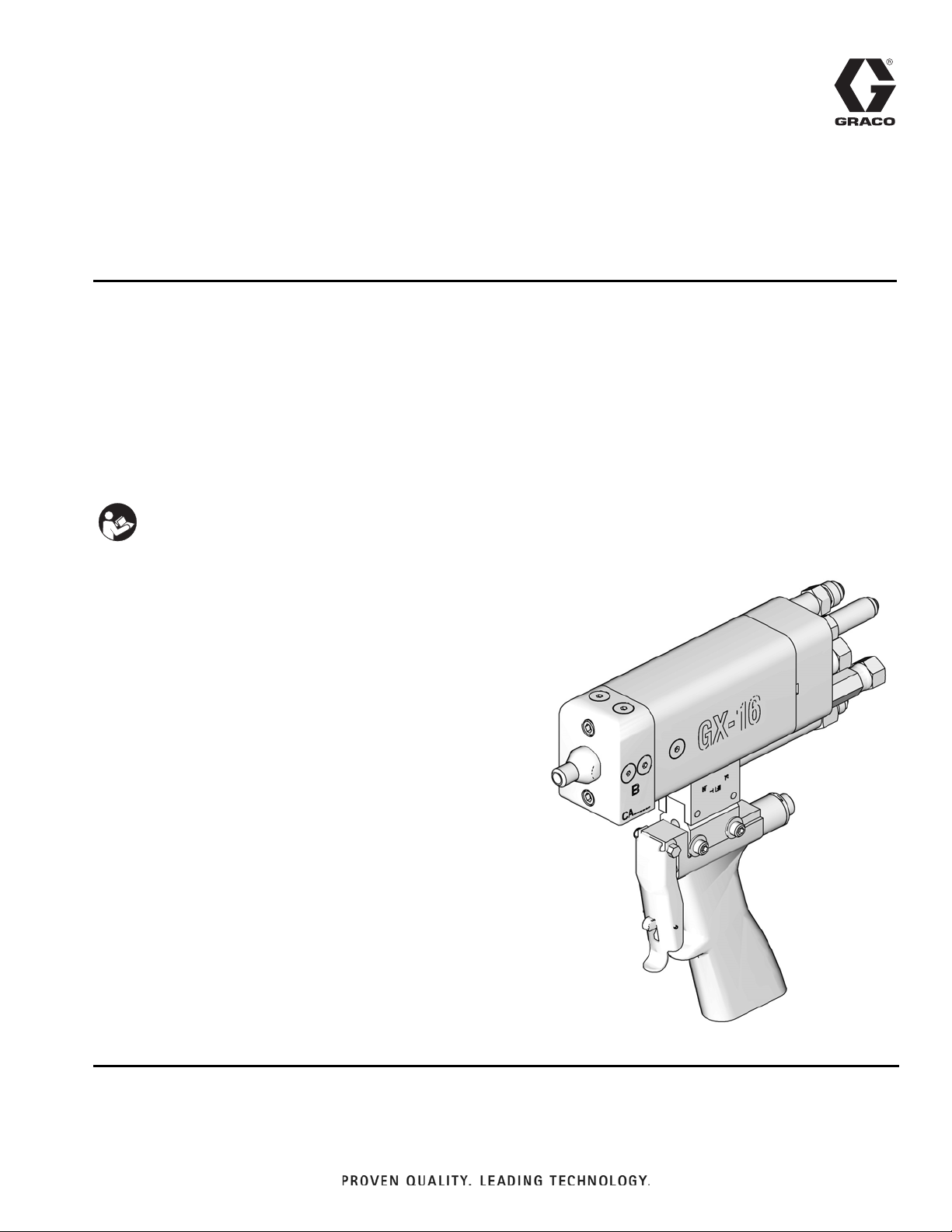
GX-16
For dispensing polyol and isocyanate materials only. For professional use only.
For indoor use only. Not approved for use in European explosive atmosphere
requirements.
3000 psi (21 MPa, 207 bar) Maximum Fluid Working Pressure
2500 psi (17 MPa, 172 bar) Maximum Hydraulic Working Pressure
180°F (82°C) Maximum Fluid Temperature
Important Safety Instructions
Read all warnings and instructions in this
manual. Save these instructions.
EN
Model 257496 shown
ti12896a
Page 2

Contents
Models . . . . . . . . . . . . . . . . . . . . . . . . . . . . . . . . . . . 3
Warnings . . . . . . . . . . . . . . . . . . . . . . . . . . . . . . . . . 4
Important Two-Component Material Information . 6
Isocyanate Conditions . . . . . . . . . . . . . . . . . . . . . 6
For all applications except spray foam . . . . . . . . 7
Material Self-ignition . . . . . . . . . . . . . . . . . . . . . . 7
Keep Components A and B Separate . . . . . . . . . 7
Moisture Sensitivity of Isocyanates . . . . . . . . . . . 7
Foam Resins with 245 fa Blowing Agents . . . . . . 8
Changing Materials . . . . . . . . . . . . . . . . . . . . . . . 8
. . . . . . . . . . . . . . . . . . . . . . . . . . . . . . . . . . . . . . 8
Grounding . . . . . . . . . . . . . . . . . . . . . . . . . . . . . . . . 8
Trigger Lock . . . . . . . . . . . . . . . . . . . . . . . . . . . . . . . 9
Setup . . . . . . . . . . . . . . . . . . . . . . . . . . . . . . . . . . . . 10
Gun Connections . . . . . . . . . . . . . . . . . . . . . . . 10
Fluid Line . . . . . . . . . . . . . . . . . . . . . . . . . . . . . 11
Gun Setup . . . . . . . . . . . . . . . . . . . . . . . . . . . . . 11
Shutoff Valve Setup . . . . . . . . . . . . . . . . . . . . . 12
Mounting . . . . . . . . . . . . . . . . . . . . . . . . . . . . . . 12
Startup . . . . . . . . . . . . . . . . . . . . . . . . . . . . . . . . . . 13
Operation . . . . . . . . . . . . . . . . . . . . . . . . . . . . . . . . 14
Theory of Operation . . . . . . . . . . . . . . . . . . . . . 14
Pressure Relief Procedure . . . . . . . . . . . . . . . . . . 15
Shutdown . . . . . . . . . . . . . . . . . . . . . . . . . . . . . . . . 15
Maintenance . . . . . . . . . . . . . . . . . . . . . . . . . . . . . 16
Recommended Tools . . . . . . . . . . . . . . . . . . . . 16
Grease the Gun . . . . . . . . . . . . . . . . . . . . . . . . 16
Recommended Hydraulic Oil . . . . . . . . . . . . . . 16
Recommended Grease . . . . . . . . . . . . . . . . . . . 16
Clean and Service the Orifices and Filters . . . . 17
Proximity Switch Replacement Procedure . . . . 18
Troubleshooting . . . . . . . . . . . . . . . . . . . . . . . . . . 19
Parts . . . . . . . . . . . . . . . . . . . . . . . . . . . . . . . . . . . . 20
Gun Models 257496, 257498, 257499,
257505, 257506, 257507, 24J187, 24E876 20
Gun Models 257492, 257493, 257494, 257495 22
Gun Models 257497, 257502, 257503, 257504,
24E877, 24E878 . . . . . . . . . . . . . . . . . . . . . 24
Gun Models 24K233, 24K234 . . . . . . . . . . . . . . 26
Dispenser Models 257513, 257514, 257515,
26D028 . . . . . . . . . . . . . . . . . . . . . . . . . . . . 28
Gun Models 26C466, 25E973, 25E974, 25E975,
25P154, 25R248, 25R249, 25E998, 25E999 30
Orifices . . . . . . . . . . . . . . . . . . . . . . . . . . . . . . . 32
Gun Handle Kit 24K223 . . . . . . . . . . . . . . . . . . 33
Gun Handle Models 257509, 257510 . . . . . . . . 34
Gun Handle Model 26C463 . . . . . . . . . . . . . . . . 35
Pour Handle Models 257594, 257596 . . . . . . . . 37
Optional Shutoff Valve Kit . . . . . . . . . . . . . . . . . 38
Accessories . . . . . . . . . . . . . . . . . . . . . . . . . . . . . . 39
Dimensions . . . . . . . . . . . . . . . . . . . . . . . . . . . . 40
. . . . . . . . . . . . . . . . . . . . . . . . . . . . . . . . . . . . . . 40
Technical Data . . . . . . . . . . . . . . . . . . . . . . . . . . . . 41
Weight . . . . . . . . . . . . . . . . . . . . . . . . . . . . . . . 41
California Proposition 65 . . . . . . . . . . . . . . . . . . . 41
Graco Standard Warranty . . . . . . . . . . . . . . . . . . . 42
Graco Information . . . . . . . . . . . . . . . . . . . . . . . . . 42
2 313536W
Page 3

Models
Part No. Description
257492† GX-16 Pour Gun, 24:1, Pour Handle, Right Side Chemical Tubes,
Star-Shaped Trigger Switch Connector
257493† GX-16 Pour Gun, 24:1, Pour Handle, Left Side Chemical Tubes,
Star-Shaped Trigger Switch Connector
257494† GX-16 Pour Gun, 24:1, Pour Handle, Right Side Chemical Tubes, Cir-
cular Trigger Switch Connector
257495† GX-16 Pour Gun, 24:1, Pour Handle, Left Side Chemical Tubes, Cir-
cular Trigger Switch Connector
257496† GX-16 Pour Gun, 24:1, Isolated Pistol Handle
257497† GX-16 Pour Gun, 24:1, No Handle
257498† GX-16 Pour Gun, No Handle, No Orifice
257499† GX-16 Pour Gun, Reverse Block, No Handle, No Orifice
257502† GX-16 Pour Gun, 1:1, No Handle
257503† GX-16 Pour Gun, 1:1, No Handle, No Fittings
257504† GX-16 Pour Gun, 1:1, No Handle, 3 ft Hoses
257505† GX-16 Pour Gun, 1:1, Pistol Handle, No Orifice, Proximity Switch
257506† GX-16 Pour Gun, 1:1, Isolated Pistol Handle, Proximity Switch
257507† GX-16 Pour Gun, 1:1, Isolated Pistol Handle, No Orifice, Proximity
Switch
24E876†
24E877† GX-16 Pour Gun, HFR, NVH, Right, 24:1
24E878† GX-16 Pour Gun, HFR, NVH, Right, Basic
24J187† GX-16 Pour Gun, HFR, NVH, Straight, 24:1
24K233† GX-16 Pour Gun, HFR, NVH, Left, 24:1
24K234† GX-16 Pour Gun, HFR, NVH. Left, Basic
25E973 GX-16 Pour Gun, No Handle, 1:1, PEEK Nozzle
25E974 GX-16 Pour Gun, No Handle, 24:1, PEEK Nozzle
25E975 GX-16 Pour Gun, LED Handle, 1:1, Magnetic Nozzle
25E998 GX-16 Pour Gun, LED Handle, 1:1, 10mm Nozzle
25E999 GX-16 Pour Gun, No Handle, 1:1, 10mm Nozzle
26C466 GX-16 Pour Gun, LED Handle, 24:1, Magnetic Nozzle
25R248 GX-16 Pour Gun, LED Handle, 24:1, Plain Nozzle
25P155 GX-16 Pour Gun, No Handle, 2:1, Plain Nozzle
25P154 GX-16 Pour Gun, LED Handle, 2:1, Plain Nozzle
25R249 GX-16 Pour Gun, LED Handle, 1:1, Plain Nozzle
GX-16 Pour Gun, HFR™, NVH, Straight, Basic
Models
Models used specifically for HFR machines.
Models used specifically for HFR-NVH machines.
† Models are CE approved.
313536W 3
Page 4
Warnings
Warnings
The following warnings are for the setup, use, grounding, maintenance, and repair of this equipment. The exclamation point symbol alerts you to a general warning and the hazard symbol refers to procedure-specific risk. Refer back
to these warnings. Additional, product-specific warnings may be found throughout the body of this manual where
applicable.
WARNING
TOXIC FLUID OR FUMES HAZARD
Toxic fluids or fumes can cause serious injury or death if splashed in the eyes or on skin, inhaled or
swallowed.
• Read Safety Data Sheet (SDS) for handling instructions and to know the specific hazards of the
fluids you are using, including the effects of long-term exposure.
• When spraying, servicing equipment, or when in the work area, always keep work area well
ventilated and always wear appropriate personal protective equipment. See Personal Protective
Equipment warnings in this manual.
• Store hazardous fluid in approved containers, and dispose of it according to applicable guidelines.
PERSONAL PROTECTIVE EQUIPMENT
Always wear appropriate personal protective equipment and cover all skin when spraying, servicing
equipment, or when in the work area. Protective equipment helps prevent serious injury, including
long-term exposure; inhalation of toxic fumes, mists or vapors; allergic reaction; burns; eye injury and
hearing loss. This protective equipment includes but is not limited to:
• A properly fitting respirator, which may include a supplied-air respirator, chemically impermeable
gloves, protective clothing and foot coverings as recommended by the fluid manufacturer and local
regulatory authority.
• Protective eyewear and hearing protection.
SKIN INJECTION HAZARD
High-pressure fluid from dispensing device, hose leaks, or ruptured components will pierce skin. This
may look like just a cut, but it is a serious injury that can result in amputation. Get immediate surgical
treatment.
• Engage trigger lock when not dispensing.
• Do not point dispensing device at anyone or at any part of the body.
• Do not put your hand over the fluid outlet.
• Do not stop or deflect leaks with your hand, body, glove, or rag.
• Follow the Pressure Relief Procedure when you stop dispensing and before cleaning, checking,
or servicing equipment.
• Tighten all fluid connections before operating the equipment.
• Check hoses and couplings daily. Replace worn or damaged parts immediately
4 313536W
Page 5
Warnings
WARNING
EQUIPMENT MISUSE HAZARD
Misuse can cause death or serious injury.
• Do not operate the unit when fatigued or under the influence of drugs or alcohol.
• Do not exceed the maximum working pressure or temperature rating of the lowest rated system component.
See Technical Data in all equipment manuals.
• Use fluids and solvents that are compatible with equipment wetted parts. See Technical Data in all equip-
ment manuals. Read fluid and solvent manufacturer’s warnings. For complete information about your material,
request MSDS from distributor or retailer.
• Do not leave the work area while equipment is energized or under pressure. Turn off all equipment and follow
the Pressure Relief Procedure when equipment is not in use.
• Check equipment daily. Repair or replace worn or damaged parts immediately with genuine manufacturer’s
replacement parts only.
• Do not alter or modify equipment.
• Use equipment only for its intended purpose. Call your distributor for information.
• Route hoses and cables away from traffic areas, sharp edges, moving parts, and hot surfaces.
• Do not kink or over bend hoses or use hoses to pull equipment.
• Keep children and animals away from work area.
• Comply with all applicable safety regulations.
FIRE AND EXPLOSION HAZARD
Flammable fumes, such as solvent and paint fumes, in work area can ignite or explode. To help prevent fire and
explosion:
• Use equipment only in well ventilated area.
• Eliminate all ignition sources; such as pilot lights, cigarettes, portable electric lamps, and plastic drop cloths
(potential static arc).
• Keep work area free of debris, including solvent, rags and gasoline.
• Do not plug or unplug power cords, or turn power or light switches on or off when flammable fumes are pres-
ent.
• Ground all equipment in the work area. See Grounding instructions.
• Use only grounded hoses.
• Hold gun firmly to side of grounded pail when triggering into pail.
• If there is static sparking or you feel a shock, stop operation immediately. Do not use equipment until you
identify and correct the problem.
• Keep a working fire extinguisher in the work area.
BURN HAZARD
Equipment surfaces and fluid that’s heated can become very hot during operation. To avoid severe burns:
• Do not touch hot fluid or equipment.
PRESSURIZED ALUMINUM PARTS HAZARD
Use of fluids that are incompatible with aluminum in pressurized equipment can cause serious chemical reaction
and equipment rupture. Failure to follow this warning can result in death, serious injury, or property damage.
• Do not use 1,1,1-trichloroethane, methylene chloride, other halogenated hydrocarbon solvents or fluids con-
taining such solvents.
• Many other fluids may contain chemicals that can react with aluminum. Contact your material supplier for
compatibility.
313536W 5
Page 6
Important Two-Component Material Information
Important Two-Component Material Information
Isocyanate Conditions
Spraying or dispensing fluids that contain isocyanates creates potentially harmful mists, vapors, and atomized
particulates.
• Read and understand the fluid manufacturer’s warnings and Safety Data Sheet (SDS) to know specific haz-
ards and precautions related to isocyanates.
• Use of isocyanates involves potentially hazardous procedures. Do not spray with this equipment unless you
are trained, qualified, and have read and understood the information in this manual and in the fluid manufacturer’s application instructions and SDS.
• Use of incorrectly maintained or mis-adjusted equipment may result in improperly cured material.which
could cause off gassing and offensive odors. Equipment must be carefully maintained and adjusted according to instructions in the manual.
• To prevent inhalation of isocyanate mists, vapors and atomized particulates, everyone in the work area
must wear appropriate respiratory protection. Always wear a properly fitting respirator, which may include
a supplied-air respirator. Ventilate the work area according to instructions in the fluid manufacturer’s SDS.
• Avoid all skin contact with isocyanates. Everyone in the work area must wear chemically impermeable
gloves, protective clothing and foot coverings as recommended by the fluid manufacturer and local regulatory authority. Follow all fluid manufacturer recommendations, including those regarding handling of contaminated clothing. After spraying, wash hands and face before eating or drinking.
• Hazard from exposure to isocyanates continues after spraying. Anyone without appropriate personal protective equipment must stay out of the work area during application and after application for the time period
specified by the fluid manufacturer. Generally this time period is at least 24 hours.
• Warn others who may enter work area of hazard from exposure to isocyanates. Follow the recommendations of the fluid manufacturer and local regulatory authority. Posting a placard such as the following outside
the work area is recommended:
TOXIC FUMES
HAZARD
DO NOT ENTER DURING
SPRAY FOAM APPLICATION
OR FOR ___ HOURS AFTER
APPLICATION IS COMPLETE
DO NOT ENTER UNTIL:
DATE:
TIME:
6 313536W
____________
____________
Page 7

Important Two-Component Material Information
For all applications except spray foam
Spraying or dispensing fluids that contain isocyanates creates potentially harmful mists, vapors, and atomized particulates.
• Read and understand the fluid manufacturer’s warn-
ings and Safety Data Sheet (SDS) to know specific
hazards and precautions related to isocyanates.
• Use of isocyanates involves potentially hazardous pro-
cedures. Do not spray with this equipment unless you
are trained, qualified, and have read and understood
the information in this manual and in the fluid manufacturer’s application instructions and SDS.
• Use of incorrectly maintained or mis-adjusted equip-
ment may result in improperly cured material. Equipment must be carefully maintained and adjusted
according to instructions in the manual.
• To prevent inhalation of isocyanate mists, vapors, and
atomized particulates, everyone in the work area must
wear appropriate respiratory protection. Always wear a
properly fitting respirator, which may include a supplied-air respirator. Ventilate the work area according
to instructions in the fluid manufacturer’s SDS.
• Avoid all skin contact with isocyanates. Everyone in
the work area must wear chemically impermeable
gloves, protective clothing and foot coverings as recommended by the fluid manufacturer and local regulatory authority. Follow all fluid manufacturer
recommendations, including those regarding handling
of contaminated clothing. After spraying, wash hands
and face before eating or drinking.
Material Self-ignition
Keep Components A and B Separate
Cross-contamination can result in cured material in fluid
lines which could cause serious injury or damage equipment. To prevent cross-contamination:
• Never interchange component A and component B
wetted parts.
• Never use solvent on one side if it has been contami-
nated from the other side.
Moisture Sensitivity of Isocyanates
Exposure to moisture (such as humidity) will cause ISO to partially cure, forming small, hard, abrasive crystal that become
suspended in the fluid. Eventually a film will form on the surface and the ISO will begin to gel, increasing in viscosity.
NOTICE
Partially cured ISO will reduce performance and the life of all
wetted parts.
• Always use a sealed container with a desiccant dryer in
the vent, or a nitrogen atmosphere. Never store ISO in
an open container.
• Keep the ISO pump wet cup or reservoir (if installed)
filled with appropriate lubricant. The lubricant creates a
barrier between the ISO and the atmosphere.
• Use only moisture-proof hoses compatible with ISO.
• Never use reclaimed solvents, which may contain mois-
ture. Always keep solvent containers closed when not in
use.
• Always lubricate threaded parts with an appropriate
lubricant when reassembling.
NOTE: The amount of film formation and rate of crystallization
varies depending on the blend of ISO, the humidity, and the
Some materials may become self-igniting if applied too
thick. Read material manufacturer’s warnings and Safety
Data Sheet (SDS).
313536W 7
temperature.
Page 8

Grounding
Foam Resins with 245 fa Blowing Agents
Some foam blowing agents will froth at temperatures above
90°F (33°C) when not under pressure, especially if agitated.
To reduce frothing, minimize preheating in a circulation system.
Changing Materials
NOTICE
Changing the material types used in your equipment
requires special attention to avoid equipment damage
and downtime.
• When changing materials, flush the equipment
multiple times to ensure it is thoroughly clean.
• Always clean the fluid inlet strainers after flushing.
• Check with your material manufacturer for chemical compatibility.
• When changing between epoxies and urethanes
or polyureas, disassemble and clean all fluid components and change hoses. Epoxies often have
amines on the B (hardener) side. Polyureas often
have amines on the B (resin) side.
Grounding
The equipment must be grounded. Grounding reduces
the risk of static and electric shock by providing an
escape wire for the electrical current due to static build
up or in the event of a short circuit.
Pump: use ground wire and clamp (supplied). Connect
ground clamp to a true earth ground.
Gun: ground through connection to a properly grounded
fluid hose and pump.
Fluid supply container: follow local code.
Solvent pails used when flushing: follow local code.
Use only conductive metal pails, placed on a grounded
surface. Do not place the pail on a non-conductive surface, such as paper or cardboard, which interrupts
grounding continuity.
Maintain grounding continuity: When flushing or
relieving pressure, hold metal part of the gun firmly to
the side of a grounded metal pail, then trigger the gun.
8 313536W
Page 9
Trigger Lock
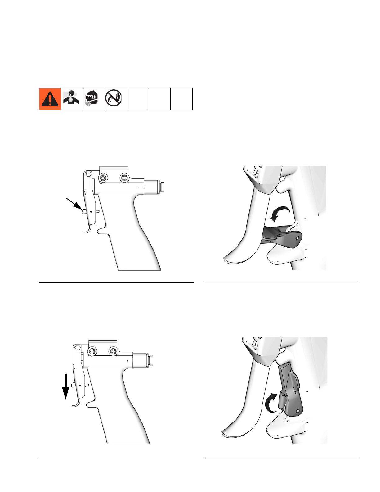
Trigger Lock
Verify that the trigger lock is engaged whenever you stop pouring to avoid accidental triggering. Check daily for
chemical build-up on trigger, trigger lock, and trigger lock spring that can prevent proper trigger lock function.
Engage
To engage the trigger lock, release the trigger. The trigger lock is spring loaded and automatically engages
when the gun trigger is released.
Trigger Lock
ti14491a1
FIG. 1: Models 257509, 257510
Disengage
To engage the trigger lock, press the trigger lock down.
ti10442a
FIG. 2: Kit 24K223
To disengage the trigger lock, press trigger lock down.
To disengage the trigger lock, press the trigger lock up.
See the following figure.
ti12896a1
ti14491a1
FIG. 3: Models 257509, 257510
313536W 9
FIG. 4: Kit 24K223
ti10441a
Page 10
Setup
Setup
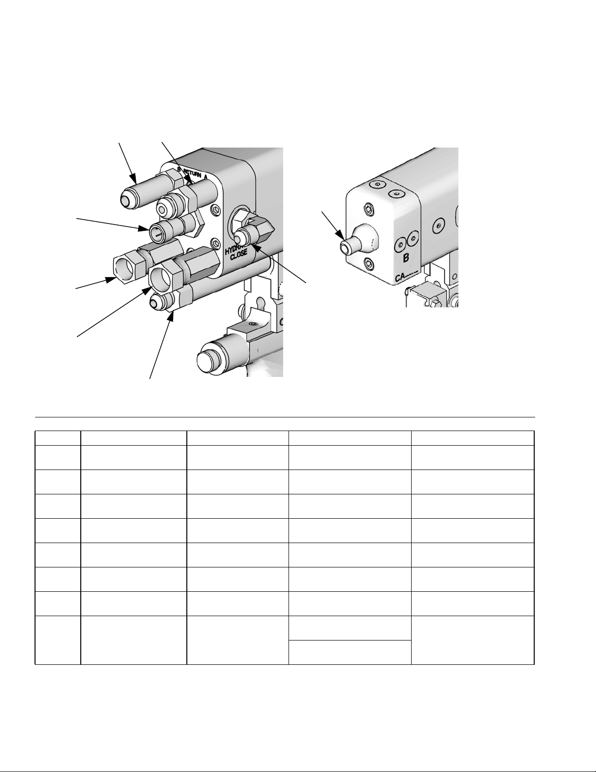
Gun Connections
D
B
H
G
C
F
A
E
ti12897a
FIG. 5
Ref Description Tape Color † Fitting Size HFR Systems Only
A
B
C
D
E
F
G
H
A Pressure Line Red
A Return Line Red and White
B Pressure Line Blue
B Return Line Blue and White
Hydraulic Open Line Green and White
Hydraulic Close Line Green
Proximity Switch or Plug
(depending on model)
Outlet Block, GX-16,
Chamber, Nozzle
NA NA NA
NA
7/16 ORG x
#6 JIC Female
7/16 ORG x
#6 JIC Male
7/16 ORG x
#5 JIC Female
7/16 ORG x
#5 JIC Male
7/16 ORG x
#4 JIC Male Extension
7/16 ORG x
#4 JIC Male Elbow
25E989, 25E999- 0.393 in
(10.0mm) dia.
All other models-0.430 in
(10.9mm)
7/16 ORG x
#5 JIC Female
7/16 ORG x
#5 JIC Male
7/16 ORG x
#6 JIC Female
7/16 ORG x
#6 JIC Male
7/16 ORG x
#4 JIC Male Extension
7/16 ORG x
#4 JIC Male Elbow
NA
† Only hoses are taped, fittings are not taped.
10 313536W
Page 11
Setup
Fluid Line
Fluid Filter: Use a 25 micron stainless steel element to
filter particles from the fluid as it leaves the pump.
Fluid Drain Valve: Required in your system, to relieve
fluid pressure in the hose and gun.
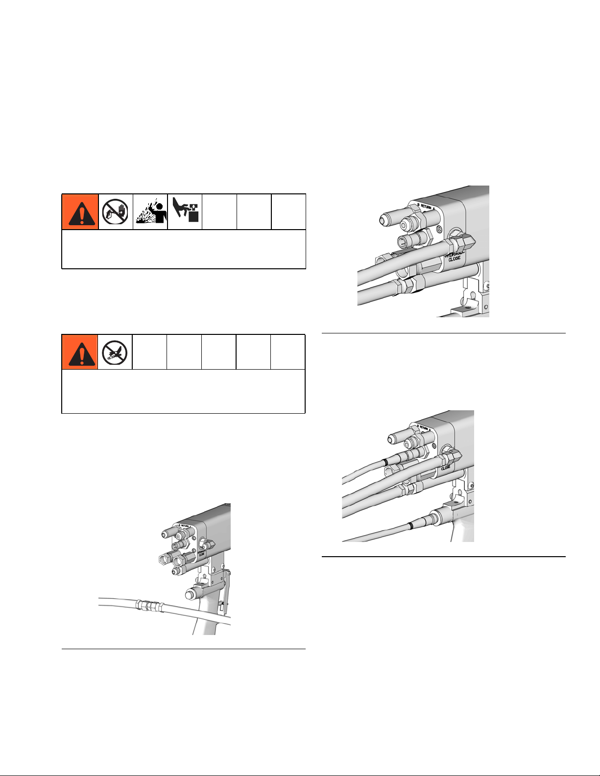
Gun Setup
Trapped air can cause the pump to cycle unexpectedly,
which could result in serious injury from splashing or
moving parts.
1. Verify hydraulic power pack is off.
2. Install hydraulic hoses to power pack.
NOTE: Pressure should not increase while air is purged
from hoses.
6. Turn off power pack. Verify no pressure exists in
hoses.
7. Remove the 7/16 in. JIC male-male adapter connecting the hydraulic hoses.
8. Attach hydraulic hoses to the gun.
ti14496a
FIG. 7
Customer supplied hydraulic hoses must be at least
1/4 in. inner diameter and rated to at least 2500 maximum working pressure.
3. Install orifice plugs.
4. Use a 7/16 in. JIC male-male adapter at the gun end
to connect hoses together. This creates a hydraulic
fluid circulation loop.
ti14495a
FIG. 6
9. Set power pack to manual mode.
10. Attach trigger switch cable and proximity switch
cable (if applicable) to gun and power pack.
ti14497a
FIG. 8
11. Verify power pack pressure is 1800 - 2500 psi.
Adjust pressure as required.
5. Turn on the power pack. Circulate oil for 3 minutes
to purge air from hydraulic hoses.
313536W 11
Page 12
Setup
12. Install chemical hoses to gun. See FIG. 5 on page
10 and FIG. 9.
ti18184a
F
IG. 9
Shutoff Valve Setup
The shutoff valves are used to control chemical flow.
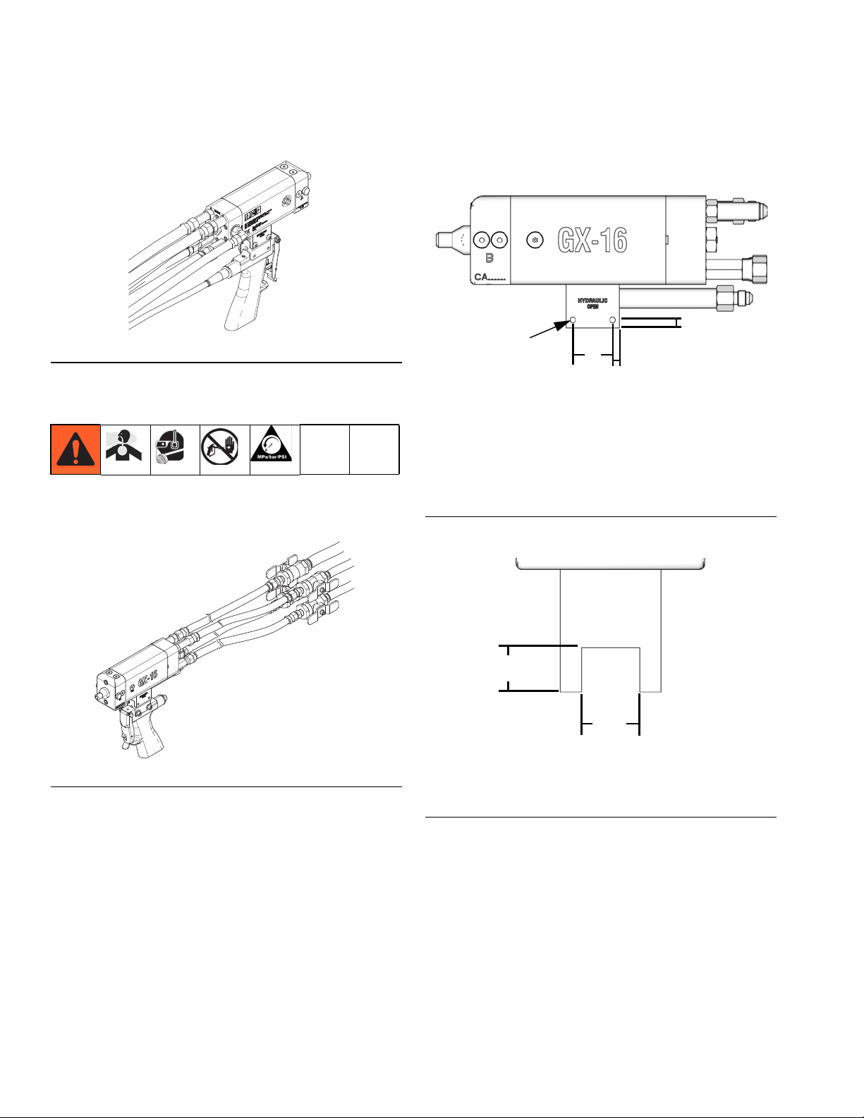
Mounting
Use the following mounting dimensions to mount the
GX-16 gun body.
D
B
A
C
A Width: 1.125 in. (28.58 mm)
B Diameter: 0.159 in. (4.04 mm),
10/32 UNF Thread on one side
C From edge: 0.188 in. (4.78 mm)
D From edge: 0.218 in. (5.54 mm)
FIG. 11: Mounting Hole Dimensions
ti14493a
ti18185a
FIG. 10: Shutoff Valve Setup
1. Perform pressure relief procedure. See Pressure
Relief Procedure on page 15.
2. Use four chemical hoses to connect shutoff valves
to gun. See FIG. 10.
3. Perform gun setup procedure to connect remaining
hoses. See Gun Setup on page 11.
4. Perform Startup procedure on page 13.
ti14492a
B
A
A Width: 0.578 in. (14.7 mm)
B Height: 0.440 in. (11.2 mm)
FIG. 12: Mounting Block Dimensions
12 313536W
Page 13
Startup
Startup
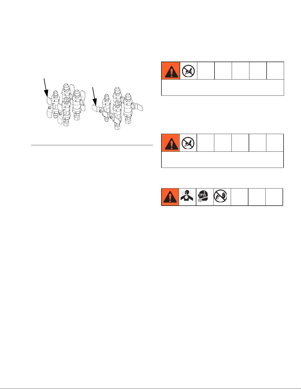
1. If your setup uses the optional shutoff valves,
rotate the handles to the “open” position.
Open Position
F
IG. 13: Shutoff Valves Positions
2. Verify cables and hoses are correctly setup. See
Gun Connections section on page 10.
3. Check for excessive wear on cables and hoses.
Replace as necessary.
Closed Position
ti18186a
4. Close dump valve on hydraulic power pack.
Hydraulic pressure must not exceed the maximum
working pressure of 2500 psi (17 MPa, 172 bar).
5. Start power pack and verify hydraulic pressure is
1800 - 2500 psi.
6. Start chemical pumps.
Chemical pressure must not exceed the maximum
working pressure of 3000 psi (21 MPa, 207 bar).
7. Verify chemical pressure is in desired range.
8. Dispense a test shot into a waste container.
9. Clean any residual material from the tip of the gun.
313536W 13
Page 14

Operation
Operation
Theory of Operation
Circulation
FDCBAE
H
Key:
A A Pressure Line
B A Return Line
C B Return Line
D B Pressure Line
E Hydraulic Open Line
F Hydraulic Close Line
G Piston Rod
H Hydraulic Piston
Dispense
FDCBAE
H
G
Key:
A A Pressure Line
B A Return Line
C B Return Line
D B Pressure Line
E Hydraulic Open Line
F Hydraulic Close Line
G Piston Rod
H Hydraulic Piston
G
FIG. 14: Circulation
Hydraulic pressure extends the piston rod to the circulation position. Material enters the material pressure line
and is sent to the material return line.
When the piston rod is extended to this position, it
removes gelled material from the nozzle assembly.
14 313536W
FIG. 15: Dispense
Hydraulic pressure retracts the piston rod to the dispense position. Material enters the A and B material
pressure lines and mixes in the mixing chamber.
When the piston rod is in this position, it blocks material
flow from entering the material return line.
Page 15

Pressure Relief Procedure
Pressure Relief
Procedure
1. If your setup uses the optional shutoff valves,
rotate the handles to the “open” position.
2. Shut down chemical pumps.
3. Drain air pressure from the A and B side chemical
tanks.
4. After tank air pressure is at zero, close the A and B
tank outlet valves.
5. Verify pressures read zero on chemical pressure
gauges.
6. Turn off hydraulic power pack.
7. Bleed hydraulic pressure via dump valve on power
pack.
Shutdown
1. Perform Pressure Relief Procedure.
2. Perform any required maintenance. See Mainte-
nance on page 16.
3. If system will not be in use for longer than two
weeks, the A and B chemical tanks must have
10 psi of dry air pressure.
NOTICE
Air must be dry. Moist air will react with isocyanate
and cause crystallization resulting in significant
component damage.
4. If the gun will not be used for longer than four
weeks, flush the gun.
8. Verify pressures read zero on hydraulic pressure
gauges.
313536W 15
Page 16

Maintenance
Maintenance
Procedure Frequency
Inspect the gun, fluid lines, trigger switch cable and, if
installed, the proximity switch cable for wear or damage
Grease the gun Weekly or Every
Clean and service the orifices and filters As Needed
Recommended Tools
• 7/16 in. open end wrench
• 3/8 in. open end wrench
• 1/8 in. allen key
• 1/4 in. allen key
• Pin vise 117661
• Drill bit (see etching on orifice for size, drill bit
should be same size as orifice)
• O-Ring Pick
• Small brass brush
• 1/4 in. brass barrel brush
• Small flashlight
• Small solvent pump can
• Cleaning rags
• Chemically impermeable gloves
• Safety glasses
• Small chemical and solvent waste container
• Grease gun
• Grease, part 0553-6
3. Use a grease gun with the required synthetic
FIG. 16: Grease Fitting
4. Use a 1/8 in. allen key to install the plug.
Recommended Hydraulic Oil
Daily
15,000 Shots
grease, part 0553-6, to purge the gun body until
grease exits the weep hole without evidence of
hydraulic oil or hardened material.
ti14494a1
NOTICE
Grease the Gun
1. Perform pressure relief procedure. See Pressure
Relief Procedure on page 15.
2. Use a 1/8 in. allen key to remove the plug.
ti12899a1
Recommended Hydraulic Oil
Use Graco-approved Hydraulic Oil, Part No.
169236 (5 gal) or 207428 (1 gal)) or a premium, ISO
grade 46 petroleum-based hydraulic oil containing
rust and oxidation inhibitors and anti-wear agents.
Before using any other type of oil in this motor, contact your Graco distributor. Unauthorized use of
lesser grade oil or substitutes may void the warranty.
Hydraulic Oil Working Temperature
The maximum hydraulic oil operating temperature is
180 °F (82 °C).
Recommended Grease
NOTICE
Recommended Grease
Use Graco-approved grease, Part No. 0553-6. This
is a synthetic grease with an operating temperature
up to 450 °F.
16 313536W
Page 17

Maintenance
Clean and Service the Orifices and Filters
Cross-contamination can result in cured material in
fluid lines which could cause serious injury or damage equipment. To prevent cross-contamination of
the equipment’s wetted parts, never interchange
component A (isocyanate) and component B (resin)
parts.
H
J
G
F
E
H
L
2. If your setup uses the optional shutoff valves,
rotate the handles to the “close” position.
3. Use a 7/16 in. wrench to remove the orifice.
4. Use a 1/8 in. allen key to remove the cleanout plug
next to the orifice.
5. Use a 1/4 in. allen key to remove the filter plug (A).
6. Remove the filter (D).
7. Use a pick to remove any hardened material from
filter.
8. Use solvent to flush residue from this side of the gun
block.
9. Use a pin vise and drill bit to carefully clean the orifice.
10. Remove the orifice o-rings.
11. Use a pick to remove any hardened material from
the orifice body.
K
12. Flush the orifice body with solvent then dry the orifice.
D
C
B
A
ti12899a
A Side
B Side
Key:
A Filter Plug
B Filter Plug O-Ring
C Filter O-Ring
D Filter
E Orifice O-Rings
F Orifice
G Grease Port Plug
H Cleanout Plug
J Cleanout Plug O-Ring
K Plug
L Plug O-Ring
FIG. 17:
NOTE: See Dispenser Models 257513, 257514,
257515, 26D028 on page 28 for applicable part num-
bers.
13. Install new o-rings on the orifice.
14. Install new filter.
15. Replace filter retainer o-ring if needed.
16. Apply grease to filter retainer threads then use a
1/4 in. allen key to install the filter retainer.
17. Apply grease to the o-ring plug threads.
18. Install o-rings then use a 1/8 in. allen key to install
cleanout plug next to the orifice.
19. Apply grease to orifice threads then install the orifice
assembly.
20. Repeat for opposite chemical side of gun.
1. Perform pressure relief procedure. See Pressure
Relief Procedure on page 15.
313536W 17
Page 18

Maintenance
Proximity Switch Replacement Procedure
1. Perform pressure relief procedure. See Pressure
Relief Procedure on page 15.
2. Remove proximity switch cable attached to proximity switch.
3. Remove proximity switch from rear of gun body.
ti12897a
FIG. 18
4. Install new proximity switch.
5. Attach proximity switch cable to proximity switch.
18 313536W
Page 19

Troubleshooting
Troubleshooting
Problem Cause Solution
Poor mixing One or both sides of gun are clogged Clean the gun, see Maintenance on
page 16
One or both orifices may need to be
replaced
Hydraulic piston not opening fast
enough due to insufficient hydraulic
pressure
No fluid being dispensed Insufficient pressure to move hydrau-
lic piston to the dispense position
Faulty proximity switch Replace proximity switch
Damaged piston u-cup seals Send gun to Graco for repair
Chemical crossover Seal failure on piston rod Send gun to Graco for repair
Hydraulic leak into divorce chamber
(hydraulic fluid found in purged
grease when greasing the gun)
Proximity switch not working Damaged proximity switch Remove and test the switch, replace
Valve opens on power up Air in hydraulic lines Disconnect hydraulic hoses from
Damaged seal u-cup Send gun to Graco for repair
Damaged proximity switch cord Remove and test the cord, replace as
Verify hydraulic unit pressure and
accumulator charge
Verify hydraulic unit pressure and
accumulator charge
as needed
needed
gun. Follow Gun Setup on page 11.
313536W 19
Page 20

Parts
Parts
Gun Models 257496, 257498, 257499, 257505, 257506, 257507, 24J187, 24E876
110
101a, c
101b, d
101
112
111
108
109
118
114
117
116
Model 257496 shown
105
105
104
104
113
106
104
107
103
104
115
ti12900a
102
Quantity by Model
Ref. Part Description
DISPENSER, GX-16, 1:1,
257513
101
. 101a
. 101b
. 101c . 122687 . PLUG, sae02, 316 ss 1 1 1
20 313536W
257514
257515
. 122685
. 261500
pre-assy
DISPENSER, GX-16, 24:1,
pre-assy
DISPENSER, GX-16, rev
block, pre-assy
. PLUG, sae02, socket head,
m, ms, 6k
. O-RING, #902, fluoroelasto-
mer
257496 257498 257499 257505 257506 257507 24J187 24E876
1 1 1
1 1 1 1
1
1 1 1 2 2 2
1 1 1 2 2 2
Page 21

Quantity by Model
Ref. Part Description
. 101d . 122679 . O-RING, epr, #902 1 1 1
257509 HANDLE, GX-16, pistol grip 1
102
257510
103 122694 SCREW, bhsc, 10-32x1.00, ms 2 2 2 2
104
105 122714 O-RING, ep, 904, 70a 2 2 2 2 2
106
107
108*
109* 261500 O-RING, #902, fluoroelastomer 1
110
111* 285967 O-RING, #006 epr 1
112* 122679 O-RING, epr, #902 1
113 15Y177 FITTING, 7/16 org x 7/16 jic ext 1 1 1 1 1 1 1 1
114
115
116
117
118
122707
122713 SWITCH, proximity 1 1 1 1 1 1
15Y178 PLUG, cavity, proximity switch 1 1
257724
257717
168518
257701
257717
298408 FITTING, 7/16 org x 9/16 jic ext 1 1 1 1 1 1
122710
122711
122708
122709
122709
122708
122710
298408 FITTING, 7/16 org x 9/16 jic ext 1 1
HANDLE, GX-16, pistol grip,
isolated
O-RING, fluoroelastomer,
#904, 75a
RESTRICTOR, orifice assy,
0.061
RESTRICTOR, orifice assy,
0.039
PACKING, o-ring, fluoroelasto-
mer
RESTRICTOR, orifice assy,
0.011
RESTRICTOR, orifice assy,
0.039
ADAPTER, jic05xsae04, mm,
ss, 6k
FITTING, elbow, 90,
jic04xsae04
ADAPTER, swivel,
jic06xsae04, fm, ss, 6k
ADAPTER, swivel,
jic05xsae04, fm, ss, 6k
ADAPTER, swivel,
jic05xsae04, fm, ss, 6k
ADAPTER, swivel,
jic06xsae04, fm, ss, 6k
ADAPTER, jic05xsae04, mm,
ss, 6k
257496 257498 257499 257505 257506 257507 24J187 24E876
1 1 1
4 4 4 6 6 6 3 3
1 1
1
1
1 1
1
1 1
1 1 1 1 1 1 1 1
1 1 1 1 1 1
1 1
1 1 1 1 1 1
1 1
1 1 1 1 1 1
Parts
* For all models, o-ring materials are marked on the
gun below the A side orifice
313536W 21
Parts are used in the maintenance of the gun. Parts
are shipped loose.
Page 22

Parts
Gun Models 257492, 257493, 257494, 257495
215
216
212
211
206
230
206
208
204
213
210
207
217
218
223
225
223
226
231
233
232
201
201b, d
201a, c
Model 257492 shown
235
236
202
234
206
214
203
229
220
219
205
221
221
209
228
228
222
224
222
227
ti12901a
22 313536W
Page 23

Quantity by Model
Ref. Part Description
201
. 201a . 122685 . PLUG, sae02, socket head, m, ms, 6k 1 1 1 1
. 201b . 261500 . O-RING, #902, fluoroelastomer 1 1 1 1
. 201c . 122687 . PLUG, sae02, 316 ss 1 1 1 1
. 201d . 122679 . O-RING, epr, #902 1 1 1 1
202
203
204
205
206
207
208
209
210
211
212
213
214
215
216
217
218
219
220
221
222
223
224
225
226
227
228
229
230
231
232
233
234
235
236
257514 DISPENSER, GX-16, 24:1, pre-assy 1 1 1 1
257594 HANDLE, GX-16, pour 1 1
257596 HANDLE, GX-16, pour 1 1
15Y246 BRACKET, hose, pour handle 1 1 1 1
122694 SCREW, bhsc, 10-32x1.00, ms 2 2 2 2
15Y247 BRACKET, hose, cylinder 1 1 1 1
122707 O-RING, fluoroelastomer, #904, 75a 4 4 4 4
122714 O-RING, ep, 904, 70a 2 2 2 2
285874 FITTING, 7/16 o-ring x 1/4 tube 90 elbow 1 1 1 1
122741 SCREW, bhcs, 1/4-20x0.50, ms 2 2 2 2
122730 ADAPTER, 1/4nptxsae04, fm, ss, 6k, 316 2 2 2 2
122731 ADAPTER, 1/4nptxsae04, fm, ms, 6k 2 2 2 2
122729 ADAPTER, 1/4nptx3/8tube, mf, ms, 5k 2 2 2 2
122732 ADAPTER, 1/4nptx3/8tub, mf, ss, 5k 2 2 2 2
122733 ADAPTER, sae04x1/4tub, mf, ms, 5k 1 1 1 1
15Y332 TUBE, a-return, left side 1 1
15Y326 TUBE, a-return, right side 1 1
15Y333 TUBE, a-supply, left side 1 1
15Y327 TUBE, a-supply, right side 1 1
15Y334 TUBE, b-return, left side 1 1
15Y328 TUBE, b-return, right side 1 1
15Y335 TUBE, b-supply, left side 1 1
15Y329 TUBE, b-supply, right side 1 1
15Y336 TUBE, hyd open, left side 1 1
15Y330 TUBE, hyd open, right side 1 1
15Y337 TUBE, hyd close, left side 1 1
15Y331 TUBE, hyd close, right side 1 1
122734 ADAPTER, 1/8nptx1/4tub, ff, ms, 5k 2 2 2 2
122735 ADAPTER, 1/4nptx3/8tub, ff, ms, 5k 2 2 2 2
122736 ADAPTER, 1/4nptx3/8tb, ff, ss, 5k, 316 2 2 2 2
122721 ADAPTER, swivel, jic6x1/4npt, fm, ms, 5k 1 1 1 1
122737 ADAPTER, swivel, 1/4nptxjic05, fm, ss, 6 1 1 1 1
122727 ADAPTER, jic05x1/4npt, mm, ss, 6k, 316 1 1 1 1
122722 ADAPTER, jic06x1/4npt, mm, ms, 6k 1 1 1 1
122726 FITTING, adapter, jic04x1/8npt 2 2 2 2
122742 SCREW, fhcs, 1/4-20x0.750, ms 2 2 2 2
122713 SWITCH, proximity 1 1 1 1
257724 RESTRICTOR, orifice assy, 0.061 1 1 1 1
168518 PACKING, o-ring, fluoroelastomer 1 1 1 1
261500 O-RING, #902, fluoroelastomer 1 1 1 1
257701 RESTRICTOR, orifice assy, 0.011 1 1 1 1
285967 O-RING, #006 epr 1 1 1 1
122679 O-RING, epr, #902 1 1 1 1
257492 257493 257494 257495
Parts are used in the maintenance of the gun. Parts
are shipped loose.
Parts
313536W 23
Page 24

Parts
Gun Models 257497, 257502, 257503, 257504, 24E877, 24E878
318
312
301a, c
301b, d
309
311
303
307
301
305
304
306
302
308
310
308
319
313
317
314
317
316
315
321
Model 257504 shown
323
322
Ref. Part Description
301
. 301a
. 301b . 261500 . O-RING, #902, fluoroelastomer 1 1 1 1
. 301c . 122687 . PLUG, sae02, 316 ss 1 1 1 1
. 301d . 122679 . O-RING, epr, #902 1 1 1 1
302
257513 DISPENSER, GX-16, 1:1, pre-assy 1 1 1
257514 DISPENSER, GX-16, 24:1, pre-assy 1 1 1
. 122685 . PLUG, sae02, socket head, m, ms,
6k 1 1 1 1
257724 RESTRICTOR, orifice assy, 0.061 1 1
257717 RESTRICTOR, orifice assy, 0.039 1 1 1
257497 257502 257503 257504 24E877 24E878
320
Quantity by Model
325
324
ti13381a
24 313536W
Page 25

Quantity by Model
Ref. Part Description
303
257701 RESTRICTOR, orifice assy, 0.011 1 1
257717 RESTRICTOR, orifice assy, 0.039 1 1 1
257497 257502 257503 257504 24E877 24E878
304 168518 PACKING, o-ring, fluoroelastomer 1 1 1 1
305
285967 O-RING, #006 epr 1
168518 PACKING, o-ring, fluoroelastomer 1 1 1
306 261500 O-RING, #902, fluoroelastomer 1 1 1 1
307
122679 O-RING, epr, #902 1
261500 O-RING, #902, fluoroelastomer 1 1 1
308 122707 O-RING, fluoroelastomer, #904, 75a 3 3 3 3 3
309
122714 O-RING, fluoroelastomer, #904, 75a 2 2 2
122707 O-RING, fluoroelastomer, #904, 75a 2 2
310 15Y177 FITTING, 7/16 org x 7/16 jic ext 1 1 1 1 1
311 122713 SWITCH, proximity 1 1 1 1 1 1
312
313
298408 FITTING, 7/16 org x 9/16 jic ext 1 1 1 1
122710 ADAPTER, jic05xsae04, mm, ss, 6k 1
122720 ADAPTER, jic06xsae04, mm, ms, 6k,
1 1 1
fluoroelastomer
124221 ADAPTER, jic05xsae04, mm, ss, 6k 1 1
314
122717 ADAPTER, swivel, jic06xsae04, fm,
ms, 6k
125541 FITTING, swivel, jic05xsae04, fm, ss,
1 1 1
1 1
6k
129342 FITTING, elbow, swivel, 90, jic06, fm, ss2 2 2
Parts
315
122715 FITTING, elbow, swivel, 90, jic05, fm,
2 2
ss
122715 FITTING, elbow, swivel, 90, jic05, fm, ss2
316
129342 FITTING, elbow, swivel, 90, jic06, fm,
2 2 2 2
ss
317
318
122718 FITTING, elbow, swivel, 90, jic04, fm, ms2 2 2 2 2
122708 ADAPTER, swivel, jic06xsae04, fm,
1 1 1 1
ss, 6k
122709 ADAPTER, swivel, jic05xsae04, fm,
1
ss, 6k
319 122711 FITTING, elbow, 90, jic04xsae04 1 1 1 1 1
320 24C481 HOSE, 3 ft, A-supply, yellow tape 1
321
24C482 HOSE, 3 ft, A-return, yellow/white
tape
1
322 24C483 HOSE, 3 ft, B-supply, green tape 1
323 24C484 HOSE, 3 ft, B-return, green/white tape 1
324 24C485 HOSE, 3 ft, hydraulic open, black tape 1
325
24C486 HOSE, 3 ft, hydraulic close,
black/white tape
1
Parts are used in the maintenance of the gun. Parts are shipped loose.
313536W 25
Page 26

Parts
Gun Models 24K233, 24K234
410
406
414
401
404
405
408
409
402
403
413
403
ti17784a
411
412
407
Model 24K233 shown
26 313536W
Page 27

Quantity
Parts
Ref. Part Description
401 257514
402 122714
403 122707
404 122720
405 122717
406 122710
407 122709
408 129342
409 122715
410 122713
411 15Y177
412 122718
413 122711
414 257701
415 257724
DISPENSER, GX-16, 24:1, pre-assy
O-RING, fluoroelastomer, #904, 75a
O-RING, fluoroelastomer, #904, 75a
ADAPTER, jic06xsae04, mm, ms, 6k, fluoroelastomer
ADAPTER, swivel, jic06xsae04, fm, ms, 6k
ADAPTER, jic05xsae04, mm, ss, 6k
ADAPTER, swivel, jic05xsae04, fm, ss, 6k
FITTING, elbow, swivel, 90, jic06, fm, ss
FITTING, elbow, swivel, 90, jic05, fm, ss
SWITCH, proximity
FITTING, 7/16 org x 7/16 jic ext
FITTING, elbow, swivel, 90, jic04, fm, ms
FITTING, elbow, 90, jic04xsae04
RESTRICTOR, orifice assy, 0.011
RESTRICTOR, orifice assy, 0.061
24K233 24K234
1 1
2 2
3 3
1 1
1 1
1 1
1 1
2 2
2 2
1 1
1 1
2 2
1 1
1
1
313536W 27
Page 28

Parts
Dispenser Models 257513, 257514, 257515, 26D028
521
517
522
526
527
522
525
528
529
524
525
r_257515_parts
522
530
522
524
524
521
523
Model 257515 shown
28 313536W
518
523
Page 29

Parts
Quantity
Ref. Part Description
257513 257514 257515 26D028
517 295229 FITTING, grease, 1/4-28 1 1 1 1
518 295693 PLUG, pipe 1 1 1 1
521 122687 PLUG, sae02, 316 ss 3
122685 PLUG, sae02, skt hd, ms, 6k 3 33
522 261500 O-RING, #902 4 54
122679 O-RING, #902 5
523 122687 PLUG, sae02, 316 ss 3
122685 PLUG, sae02, skt hd, ms, 6k 3 3 3
524 122679 O-RING, #902 4
261500 O-RING, #902 3 4 3
525 285917PKG SCREEN, 230 micron 22
526 15X857 PLUG, filter 11
15X858 PLUG, filter 1 1
527 122681 O-RING, #906 1 11
122680 O-RING, #906 1
528 15X858 PLUG, filter 11
15X857 PLUG, filter 1 1
529 122680 O-RING, #906 1
122681 O-RING, #906 1 1 1
530 122685 PLUG, sae02, skt hd 1 1 1 1
313536W 29
Page 30

Parts
Gun Models 26C466, 25E973, 25E974, 25E975, 25P154, 25R248, 25R249, 25E998, 25E999
629
614
606
601a,c
612
601b,d
601
615
615a
615b
601e
618
618b
618a
611
628
607
607
610
613
602
30 313536W
Page 31

Ref.
Parts
Quantity
Part Description
26C465
25E972
25R538
601
25R539
257514
257513
26D028
. 601a 122685 PLUG, sae02, socket head 1 1 1 1 1 1 1 1 1 1
. 601b 261500 O-RING, #902, fkm 1 1 1 1 1 1 1 1 1 1
. 601c 122687 PLUG, sae02, 316 ss 1 1 1 1 1 1 1 1 1 1
. 601d 122679 O-RING, epr, #902 1 1 1 1 1 1 1 1 1 1
26C464
25E971
. 601e
257511
25E977
602 26C463
DISPENSER, gx-16, 24:1,
pre-assy, mag
DISPENSER, gx-16, 24:1,
pre-assy, ring
DISPENSER, gx-16, 1:1,
pre-assy, mag
DISPENSER, gx-16, 1:1,
pre-assy, ring
DISPENSER, gx-16, 24:1,
pre-assy, plain
DISPENSER, gx-16, 1:1,
pre-assy, plain
DISPENSER, gx-16, 1:1,
pre-assy, 10mm
BLOCK, gx-16, chamber,
magnet
BLOCK, gx-16, chamber,
non-magnet
BLOCK, gx-16, chamber,
plain
BLOCK, gx-16, chamber,
10mm
KIT, handle, gx-16, hfr, nvh,
led
26C466
1
1 1
1 11 11 1 1
25E973
24:1 MAG
1
11
25E974
1:1 RING
24:1 RING
1
25E975
1:1 MAG
1
25P155
25R248
24:1 PLAIN
25P154
2:1 PLAIN
2:1 PLAIN
25R249
1:1 PLAIN
111
1
1111
25E989
1:1 10mm
11
11
606 122714 O-RING, ep 2 2 2 2 2 2 2 2 2 2
607 122707 O-RING, fkm 3 3 3 3 3 3 3 3 3 3
610 15Y177 FITTING 1 1 1 1 1 1 1 1 1 1
611 122711 FITTING, elbow 1 1 1 1 1 1 1 1 1 1
612 122713 SWITCH, prox 1 1 1 1 1 1 1 1 1 1
613 122709 ADAPTER, swivel 1 1 1 1 1 1 1 1 1 1
614 122710 ADAPTER 1 1 1 1 1 1 1 1 1 1
257712
615
257701
257713
. 615a 122679 O-RING, epr 1 1 1 1 1 1 1 1 1 1
. 615b 285967 O-RING, epr 1 1 1 1 1 1 1 1 1 1
257712
618
257724
257717
. 618a 122679 O-RING, epr 1 1 1 1 1 1 1 1 1 1
. 618b 285967 O-RING, epr 1 1 1 1 1 1 1 1 1 1
RESTRICTOR, orifice
assembly, .029
RESTRICTOR, orifice
assembly .011
RESTRICTOR, orifice
assembly .032
RESTRICTOR, orifice
assembly, .029
RESTRICTOR, orifice
assembly, .061
RESTRICTOR, orifice
assembly, .039
1 11 111
1 1
11
1 1 111
1 1 1
11
628 122708 ADAPTER, swivel 1 1 1 1 1 1 1 1 1 1
629 298408 FITTING 1 1 1 1 1 1 1 1 1 1
25E990
1:1 10mm
313536W 31
Page 32

Parts
Orifices
Part Orifice Assembly Size
257700 Orifice Plug
257701 0.011 in.
257702 0.013 in.
257703 0.016 in.
257704 0.018 in.
257705 0.020 in.
257706 0.022 in.
257707 0.023 in.
257708 0.024 in.
257709 0.025 in.
257710 0.026 in.
257711 0.028 in.
257712 0.029 in.
257713 0.032 in.
257714 0.035 in.
257715 0.036 in.
257716 0.038 in.
257717 0.039 in.
257718 0.040 in.
257719 0.042 in.
257720 0.043 in.
257721 0.044 in.
257722 0.049 in.
257723 0.052 in.
257724 0.061 in.
24K682 0.085 in.
NOTE: O-rings and cleanout drill bits are included in all
orifice parts listed.
32 313536W
Page 33

Gun Handle Kit 24K223
702
703
Parts
706
705
704
701
ti17785a
Ref. Part Description Qty
701 24D073 KIT, handle, EP 1
702 16H435 ISOLATOR, handle, GX-16 to MD2 1
703 16H436 ISOLATOR, handle, GX-16 to MD2, left 1
704 16H437 ISOLATOR, handle, GX-16 to MD2, right 1
705 122694 SCREW, button head 2
706 121070 SCREW, machine 2
313536W 33
Page 34

Parts
Gun Handle Models 257509, 257510
809
807
808
810
811
812
803
802
806
Model 257510 shown
Ref. Part Description Qty
801 257576 HANDLE 1
802 112095 SCREW, set 1
803 257578 SWITCH, trigger 1
804 299650 SPRING 1
805 257577 PLUNGER, spring 1
806 15Y159 NUT, retainer 1
807 257579 TRIGGER, safety, gun 1
808 295671 SCREW, mounting, trigger 1
809 295438 NUT, stop, elastic, 5-40 1
810 15Y160 ISOLATOR, handle
(Model 257510 only)
811 122706 WASHER, flat, #10, ms, 1/2od, 0.49 thick
(Model 257510 only)
812 105210 SCREW, 10-32 x 1 shcs (matrix)
(Model 257510 only)
805
804
ti13383a
801
1
2
2
34 313536W
Page 35

Gun Handle Model 26C463
Parts
927
924
906
904
901
922
925
923
908
907
926
921
905
Pinout
903
902
Ref. Part Description Qty
901 15K666 HANDLE, 2K dispense valve, electric 1
902 276745 STOP, trigger 1
903 112033 PIN, dowel 1
904 15B209 TRIGGER, gun 1
905 192272 PIN, pivot 1
906 203953 SCREW, cap hex hd 1
907 15K668 PLUNGER, trigger, 2K handle 1
908 551396 SPRING, .26 x .37 x .51 music wire 1
922 16H435 ISOLATOR, handle, GX-16 to MD2 1
923 16H436 ISOLATOR, handle, GX-16 to MD2, left 1
924 16H437 ISOLATOR, handle, GX-16 to MD2, right 1
925 122694 SCREW, bhsc, 10 x 1.00, ms 2
926 121070 SCREW, machine, #8 x 1.375 2
927 25E988 KIT, led handle 1
313536W 35
Page 36

Parts
LED Trigger for HFR-NVH
The HFR setup Advanced #7 screen contains the following control options for gun handle 26C463:
• Control Dispense Ready Light – Checking this
option will reassign the I/O originally used to sense
an optional hydraulic tank low level sensor to an
output for driving a ready lamp. Typically a ready
lamp (LED) is installed in the handle of a dispense
valve.
NOTE: This option can only be enabled when using
software version 1.15.079 of 16E122 or later.
a. Not Ready (Dark or OFF) - This will occur when
not in a dispense mode (disable or night
modes), the user is on a setup screen when
idle, an alarm is active, the system is in low
pressure recirculation mode or not moving (full
recirculation type systems only), the system is
performing a manual or semi-automatic recirculation operation (Auto Circulate Between Dispenses is OFF), or when the stall to pressure
logic is OFF (Fusion/P2 dispense valve type
systems only).
b. Ready (LED is flashing at a rate of 4 hertz) -
This will occur when all conditions outlined in
the previous state are NOT true, the system is
idle (or in high pressure recirculation mode if
using a full recirculation system), and when the
system is NOT dispensing.
c. Dispensing (LED is ON) - This will occur when
the system is actively dispensing material out of
the valve, or when recirculating material through
a manual or semi-automatic recirculation kit.
When this function is checked or turned ON, the
ready lamp will be in one of the following states:
36 313536W
Page 37

Pour Handle Models 257594, 257596
1002
1001
1008
1004
1007
1009
Parts
1002
1010
1005
1006
Model 257594 shown
Ref. Part Description Qty
1001 295438 NUT, stop, elastic, 5-40 1
1002 122746 SCREW, shc, 10-32x.375, ms, nyloc 4
1003 257595 CONTROL, circular connector/led
(assembly 257594 only)
257597 CONTROL, star-shaped connector/led
(assembly 257596 only)
1004 295671 SCREW, mounting, trigger 1
1005 15Y276 CLIP, expander, female 1
1006 257593 CHOCK, male expander, w/pin 1
1007 122747 SCREW, shc, 110-32x0.75, ms 1
1008 15Y277 TRIGGER, pour gun 1
1009 15Y278 MODULE, pour handle mount, w/holes 1
1010 15Y280 FLANGE 1
1003
ti14499a
1
1
313536W 37
Page 38

Parts
Optional Shutoff Valve Kit
1102
1
1101
1104
1
1103
1101
1
1107
1
1106
1
1
24L498 Shown
1
Apply items 8 and 9 as required
1105
ti18187a
Quantity
Ref. Part Description
24L498, KIT,
valve shutoff,
GX-16
24M596, KIT,
valve shutoff,
GX-16, NVH
1101 --- VALVE, ball, 2 way, 1/4 NPT, female 4 4
1102 --- ADAPTER, 1/2-20 JIC x 1/4 NPT 2
--- ADAPTER, JIC08x1/4, MS 2
1103 --- ADAPTER, JIC06x1/4, SS 2 2
1104 --- ADAPTER, JIC06x1/4 NPT, MS 1
--- ADAPTER, swivel, JIC05x1/4 NPT, MS 1
1105 --- ADAPTER, swivel, JIC06x1/4 NPT, MS 1
--- ADAPTER, swivel, JIC05x1/4 NPT, MS 1
1106 --- ADAPTER, JIC05x1/4 NPT, SS 1
--- ADAPTER, swivel, JIC06x1/4 NPT, MS 1
1107 --- ADAPTER, swivel, 1/4 NPTxJIC05, SS 1
--- ADAPTER, swivel, JIC06x1/4 NPT, MS 1
1108 --- TAPE, TFE, sealant 1 1
1109 --- SEALANT, pipe, SST 1 1
38 313536W
Page 39

Accessories
Description Part
Hose Kit 24C999
Gun Cover, straight fittings 123694
Gun Cover, 90 deg. fittings 124226
Hose Cover, 12 ft 123698
Right Fitting Adapter Kit 24K672
Left Fitting Adapter Kit 24K674
Grease Fitting Flush Kit 24T326
Accessories
313536W 39
Page 40

Accessories
Dimensions
B
A
C
ti12896a
Model 257496 shown
Model
257492, 257493, 257494, 257495 15.1 (383) 9.6 (244) 7.9 (201)
257497, 257502, 257503, 257504, 24E877,
24E878, 24K233, 24K234
(no hoses)
257496, 257507, 26C466, 25E975, 25P154,
25R248, 25R249, 25E998
257505, 257506 9.3 (236) 3.0 (76) 8.1 (206)
257498, 257499, 24J187, 24E876, 25E973,
25E974, 25E999
10.3 (262) 3.6 (91) 3.7 (94)
9.3 (236) 3.0 (76) 8.9 (226)
9.3 (236) 2.8 (71) 3.7 (94)
Dimension
ABC
40 313536W
Page 41

Technical Data
Technical Data
Maximum Fluid Working Pressure . . . . . . . . . . . . . . . . . . 3000 psi (21 MPa, 207 bar)
Maximum Hydraulic Working Pressure . . . . . . . . . . . . . . 2500 psi (17 MPa, 172 bar)
Maximum Fluid Temperature . . . . . . . . . . . . . . . . . . . . . . 180°F (82°C)
Fitting Sizes . . . . . . . . . . . . . . . . . . . . . . . . . . . . . . . . . . . See Gun Connections section on page 10
Max Sound Power Level . . . . . . . . . . . . . . . . . . . . . . . . . 68.5 dB
Wetted Parts. . . . . . . . . . . . . . . . . . . . . . . . . . . . . . . . . . . Aluminum, stainless steel, carbon steel, disogrin (ure-
thane), Rulon, EPDM, fluoroelastomer, PTFE
Flow Rate, lb/min (kg/min) . . . . . . . . . . . . . . . . . . . . . . . . 4.6 to 40 (2 to 18)
Weight
Model Weight*, lb (kg)
257492, 257493,
257494, 257495 8.1 (3.7)
257497, 257502,
257503, 257504,
24E877, 24E878,
24K233, 24K234
(no hoses) 5.0 (2.3)
257496, 257507,
26C466, 25E975,
25P154, 25R248,
25R249, 25E998 5.2 (2.4)
257505, 257506 5.1 (2.3)
257498, 257499,
24J187, 24E876,
25E973, 25E974,
25E999 4.6 (2.1)
* Weights are approximate.
California Proposition 65
CALIFORNIA RESIDENTS
WARNING: Cancer and reproductive harm – www.P65warnings.ca.gov.
313536W 41
Page 42

Graco Standard Warranty
Graco warrants all equipment referenced in this document which is manufactured by Graco and bearing its name to be free from defects in
material and workmanship on the date of sale to the original purchaser for use. With the exception of any special, extended, or limited warranty
published by Graco, Graco will, for up to 250,000 dispense cycles or a period of twelve months, which ever occurs first from the date of sale, repair
or replace any part of the equipment determined by Graco to be defective. This warranty applies only when the equipment is installed, operated
and maintained in accordance with Graco’s written recommendations.
This warranty does not cover, and Graco shall not be liable for general wear and tear, or any malfunction, damage or wear caused by faulty
installation, misapplication, abrasion, corrosion, inadequate or improper maintenance, negligence, accident, tampering, or substitution of
non-Graco component parts. Nor shall Graco be liable for malfunction, damage or wear caused by the incompatibility of Graco equipment with
structures, accessories, equipment or materials not supplied by Graco, or the improper design, manufacture, installation, operation or
maintenance of structures, accessories, equipment or materials not supplied by Graco.
This warranty is conditioned upon the prepaid return of the equipment claimed to be defective to an authorized Graco distributor for verification of
the claimed defect. If the claimed defect is verified, Graco will repair or replace free of charge any defective parts. The equipment will be returned
to the original purchaser transportation prepaid. If inspection of the equipment does not disclose any defect in material or workmanship, repairs
will be made at a reasonable charge, which charges may include the costs of parts, labor, and transportation.
THIS WARRANTY IS EXCLUSIVE, AND IS IN LIEU OF ANY OTHER WARRANTIES, EXPRESS OR IMPLIED, INCLUDING BUT NOT
LIMITED TO WARRANTY OF MERCHANTABILITY OR WARRANTY OF FITNESS FOR A PARTICULAR PURPOSE.
Graco’s sole obligation and buyer’s sole remedy for any breach of warranty shall be as set forth above. The buyer agrees that no other remedy
(including, but not limited to, incidental or consequential damages for lost profits, lost sales, injury to person or property, or any other incidental or
consequential loss) shall be available. Any action for breach of warranty must be brought within two (2) years of the date of sale.
GRACO MAKES NO WARRANTY, AND DISCLAIMS ALL IMPLIED WARRANTIES OF MERCHANTABILITY AND FITNESS FOR A
PARTICULAR PURPOSE, IN CONNECTION WITH ACCESSORIES, EQUIPMENT, MATERIALS OR COMPONENTS SOLD BUT NOT
MANUFACTURED BY GRACO. These items sold, but not manufactured by Graco (such as electric motors, switches, hose, etc.), are subject to
the warranty, if any, of their manufacturer. Graco will provide purchaser with reasonable assistance in making any claim for breach of these
warranties.
In no event will Graco be liable for indirect, incidental, special or consequential damages resulting from Graco supplying equipment hereunder, or
the furnishing, performance, or use of any products or other goods sold hereto, whether due to a breach of contract, breach of warranty, the
negligence of Graco, or otherwise.
FOR GRACO CANADA CUSTOMERS
The Parties acknowledge that they have required that the present document, as well as all documents, notices and legal proceedings entered into,
given or instituted pursuant hereto or relating directly or indirectly hereto, be drawn up in English. Les parties reconnaissent avoir convenu que la
rédaction du présente document sera en Anglais, ainsi que tous documents, avis et procédures judiciaires exécutés, donnés ou intentés, à la suite
de ou en rapport, directement ou indirectement, avec les procédures concernées.
Graco Information
Sealant and Adhesive Dispensing Equipment
For the latest information about Graco products, visit www.graco.com.
For patent information, see www.graco.com/patents.
TO PLACE AN ORDER, contact your Graco distributor, go to www.graco.com, or call to identify the nearest
distributor.
If calling from the USA: 1-800-746-1334
If calling from outside the USA: 0-1-330-966-3000
All written and visual data contained in this document reflects the latest product information available at the time of publication.
GRACO INC. AND SUBSIDIARIES • P.O. BOX 1441 • MINNEAPOLIS MN 55440-1441 • USA
Copyright 2010, Graco Inc. All Graco manufacturing locations are registered to ISO 9001.
Graco reserves the right to make changes at any time without notice.
Original instructions. This manual contains English. MM 313536
Graco Headquarters: Minneapolis
International Offices: Belgium, China, Japan, Korea
www.graco.com
Revision W, February 2021
 Loading...