

Page 1
Instructions
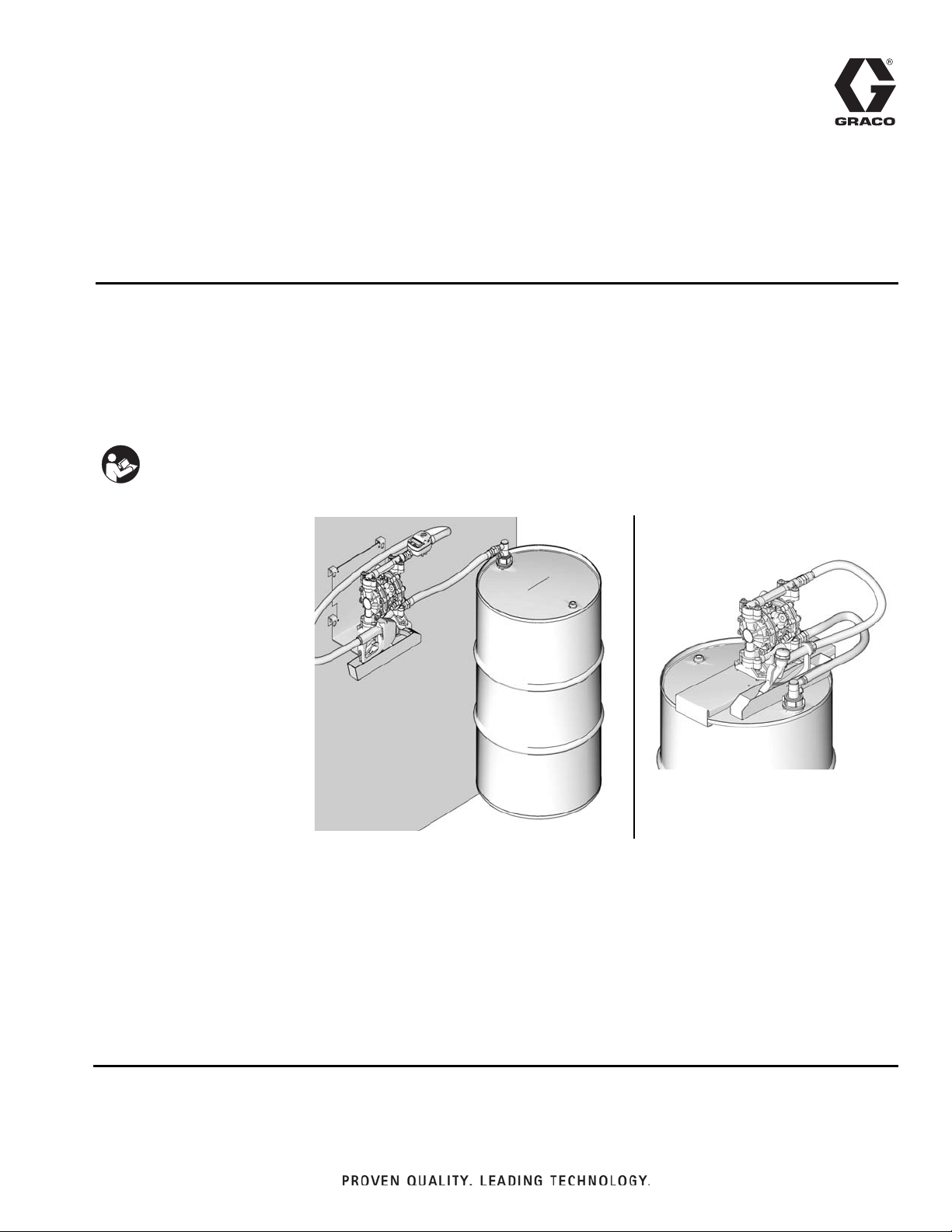
Model 24F531
Model 24F947
Diesel Exhaust
3A1189G
Fluid (DEF) System
For pumping diesel exhaust fluid. Not approved for use in European explosive atmosphere
locations. For professional use only.
50 psi (0.3 MPa, 3.4 bar) Maximum Fluid Working Pressure
50 psi (0.3 MPa, 3.4 bar) Maximum Air Input Pressure
Important Safety Instructions
Read all warnings and instructions in this
manual. Save these instructions.
EN
Model No. 24F531
Wall mounted with meter
Model No. 24F878
Wall mounted without meter
Model No. 24F947
Drum mounted without meter
Model No. 24M499
Drum mounted with meter
Related Manuals:
313048 Meter
308981 Husky Pump
Page 2
Warnings
Warnings
The following general warnings are for the setup, use, grounding, maintenance, and repair of this equipment. Additional, more specific warnings may be found throughout the body of this manual where applicable. Symbols appear-
ing in the body of the manual refer to these general warnings. When these symbols appear throughout the manual,
refer back to these pages for a description of the specific hazard.
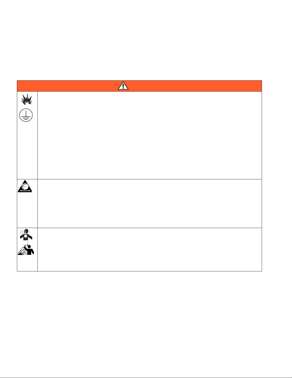
WARNING
FIRE AND EXPLOSION HAZARD
When flammable fluids are present in the work area, such as gasoline and windshield wiper fluid, be
aware that flammable fumes can ignite or explode. To help prevent fire and explosion:
• Use equipment only in well ventilated area.
• Eliminate all ignition sources, such as cigarettes and portable electric lamps.
• Keep work area free of debris, including rags and spilled or open containers of solvent and gasoline.
• Do not plug or unplug power cords or turn lights on or off when flammable fumes are present.
• Ground all equipment in the work area.
• Use only grounded hoses.
• If there is static sparking or you feel a shock, stop operation immediately. Do not use equipment
until you identify and correct the problem.
• Keep a working fire extinguisher in the work area.
PRESSURIZED EQUIPMENT HAZARD
Fluid from the gun/dispense valve, leaks, or ruptured components can splash in the eyes or on skin and
cause serious injury.
• Follow the Pressure Relief Procedure when you stop spraying and before cleaning, checking, or
servicing equipment.
• Tighten all fluid connections before operating the equipment.
• Check hoses, tubes, and couplings daily. Replace worn or damaged parts immediately.
TOXIC FLUID OR FUMES HAZARD
Toxic fluids or fumes can cause serious injury or death if splashed in the eyes or on skin, inhaled, or swallowed.
• Read MSDSs to know the specific hazards of the fluids you are using.
• Route exhaust away from work area. If diaphragm ruptures, fluid may be exhausted into the air.
• Store hazardous fluid in approved containers, and dispose of it according to applicable guidelines.
2 3A1189G
Page 3
Warnings
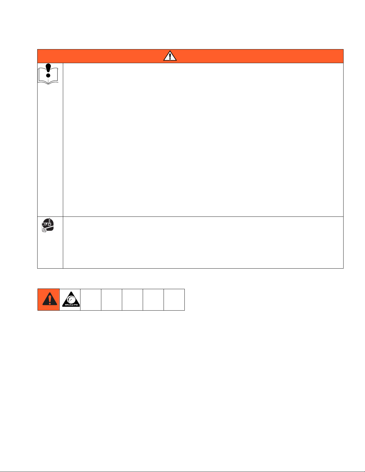
WARNING
EQUIPMENT MISUSE HAZARD
Misuse can cause death or serious injury.
• Do not operate the unit when fatigued or under the influence of drugs or alcohol.
• Do not exceed the maximum working pressure or temperature rating of the lowest rated system component. See Technical Data in all equipment manuals.
• Use fluids and solvents that are compatible with equipment wetted parts. See Technical Data in all
equipment manuals. Read fluid and solvent manufacturer’s warnings. For complete information about
your material, request MSDS from distributor or retailer.
• Do not leave the work area while equipment is energized or under pressure. Turn off all equipment
and follow the Pressure Relief Procedure when equipment is not in use.
• Check equipment daily. Repair or replace worn or damaged parts immediately with genuine manufacturer’s replacement parts only.
• Do not alter or modify equipment.
• Use equipment only for its intended purpose. Call your distributor for information.
• Route hoses and cables away from traffic areas, sharp edges, moving parts, and hot surfaces.
• Do not kink or over bend hoses or use hoses to pull equipment.
• Keep children and animals away from work area.
• Comply with all applicable safety regulations.
PERSONAL PROTECTIVE EQUIPMENT
You must wear appropriate protective equipment when operating, servicing, or when in the operating area
of the equipment to help protect you from serious injury, including eye injury, hearing loss, inhalation of
toxic fumes, and burns. This equipment includes but is not limited to:
• Protective eye wear, and hearing protection.
• Respirators, protective clothing, and gloves as recommended by the fluid and solvent manufacturer.
Pressure Relief Procedure
Follow this Pressure Relief Procedure whenever you:
• Are instructed to relieve pressure.
• Stop dispensing.
• Check, clean or service any system equipment.
• Install or clean fluid nozzles.
1. Turn OFF air supply to pump (F
2. Open the nozzle.
3. Be sure you have a container ready to catch drainage.
IG. 1).
3A1189G 3
Page 4
Installation
K
B
G
D
J
H
C
A
F
E
L
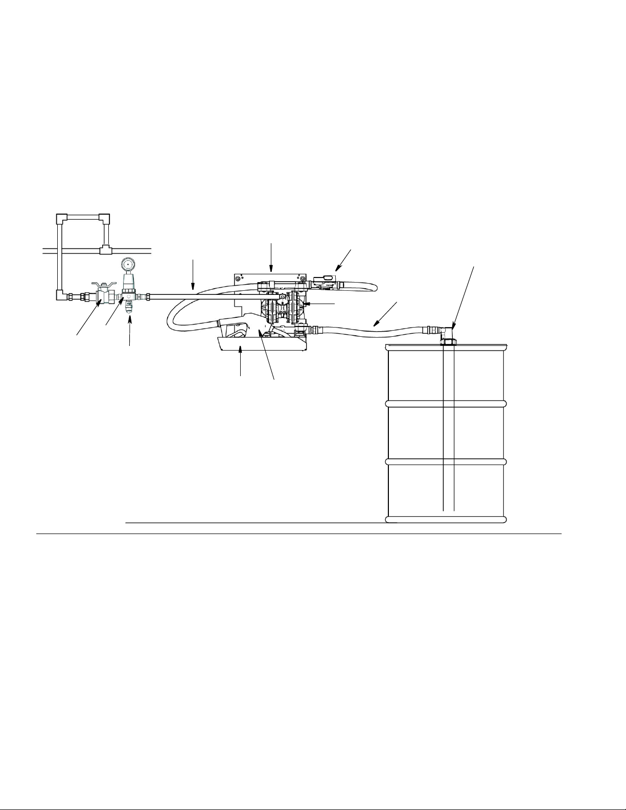
Installation
Typical Installations
Model 24F531 - Wall Mounted, with Meter
Model 24F878 - Wall Mounted, no Meter
FIG. 1
Key
APump
B Bleed-type master air valve (required for pump)
C Air supply line
D Pump air regulator
E Fluid supply hose
F Suction kit
G Wall mounting bracket
H Fluid nozzle
JMeter
K Nozzle bracket and bath
L Safety valve - set to 50 psi (3.4 bar, 0.34 MPa)
4 3A1189G
Page 5
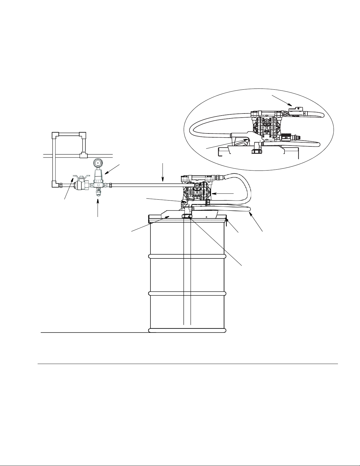
Model 24F947 - Drum Mounted without Meter
A
J
B
D
C
E
F
G
L
K
N
M
Model 24M499
Model 24F947
Model 24M499 - Drum Mounted with Meter
Installation
FIG. 2
Key
APump
B Bleed-type master air valve (required for pump)
C Air supply line
D Pump air regulator
E Fluid supply hose
F Suction kit
3A1189G 5
G Fluid nozzle
J Nozzle tray and bath
K Drum bracket
L Safety valve - set to 50 psi (3.4 bar, 0.34 MPa)
M Meter
N Fluid Nozzle
Page 6

Installation
Installation Date
Drum Bracket Label
Wall Bracket Label
General Installation Information
• The Typical Installation illustrations provided on
pages 4 - 5 are only guidelines for installing system
components. Contact your Graco distributor for
assistance in planning a system to suit your needs.
• To ensure your system is compatible with fluids
being pumped, always use genuine Graco replacement parts and accessories.
• Tighten all connections firmly to avoid air and/or
fluid leaks.
• Storage tanks should be securely anchored to prevent shifting or tipping when empty or full.
NOTICE
To maintain the integrity and purity of the AUS32
(Aqueous Urea Solution 32.5%) and ensure proper
operation of equipment:
• Once the system is assembled it must remain
sealed to insure the integrity of the fluid. Breaking the seal on the system can lead to fluid contamination.
Identification Label for CE Mark
Locate the Diesel Exhaust Fluid (DEF) System identification label adhered to the mounting bracket.
Use a permanent marker or ink pen to write the installation date in the space provided and circle the Part Number for the model you ordered.
F
IG. 3 is provided to assist you in finding the location of
this label on the bracket and the Date Code field on the
label.
• After dispensing DEF, drain all the fluid from the
nozzle, making sure it is pointing downward
when stored in the nozzle holder. DEF remaining
in the nozzle tip and exposed to air will crystallize
and can plug the nozzle.
• DO NOT lay the dispensing nozzle on the ground
or on any surface that may contaminate the nozzle tip and compromise the purity of the DEF.
FIG. 3
6 3A1189G
Page 7

Installation
B
6c
6b
6a
E
F
Pump
For complete pump instructions refer to the pump
instruction manual included with your system.
• If necessary, change the orientation of the fluid inlet
and outlet ports on the pump. See pump instruction
manual for this procedure.
• Retorque bolts per specifications.
Air Line
Alpha letters included in the following instructions refer
to letters shown in Typical Installation examples (F
F
IG. 2, pages 4 - 5).
A bleed-type master air valve (B) is required in your
system to relieve trapped air between the valve and
the pump. Trapped air can cause the pump to cycle
unexpectedly, which could result in serious injury
from fluid splashing in the eyes or on skin, injury
from moving parts or contamination from hazardous
fluids.
Locate one bleed-type master air valve (B) close to the
pump and use it to relieve trapped air (F
IG. 4). For drum
mounted installations only, also locate a second master
air valve upstream from all air line accessories and use
it to isolate them during cleaning and repair.
IG. 1 -
1. Using the hardware provided install the air controls
to the air inlet of the pump as shown in F
IG. 4. Use a
minimum 1/4 in. (6.3 mm) ID air hose.
2. Install an air line quick disconnect coupler onto the
end of the air supply line (C) and screw the matting
fitting into the pump air inlet snugly. Do not connect
the coupler to the fitting yet.
Fluid Supply Hose
Numerals used in the following instructions refer to reference numbers used in the Parts Lists provided on
pages 10 - 11.
1. Screw the fluid supply hose (9) fluid fitting into the
pump inlet snuggly. Do not overtighten.
NOTE: At the inlet, if the fluid pressure is greater than
15 psi (0.1 MPa, 1 bar) the diaphragm life will be shortened.
Fluid Suction Kit (6) - 24F532
Numerals used in the following instructions refer to reference numbers used in the Parts Lists provided on
pages 10 - 11.
The DEF System includes a Fluid Suction Kit containing
the following parts - Drum Coupler (6a), Drum Insert
(6b) and Suction Line (6c).
FIG. 5
NOTE: The suction line (6c) can be used with either a
55 gallon drum or larger totes.
FIG. 4
• If using with a large tote
tion line.
• If using with a 55 gallon drum
line to 39 inches (991 mm). Remove all burrs.
: Do NOT trim the suc-
: Trim the suction
3A1189G 7
Page 8

Installation
The suction line is designed to allow for full evacuation
of the container so it will bend slightly when installed.
1. Connect suction tube (6c) to drum insert (6b) to
pump.
2. Insert suction line (6c) into drum.
3. Install drum coupler (6a) into drum insert (6b)
4. Connect hose (E) to pump fitting. Use a flat-blade
screw driver to tighten hose clamp (F).
5. Connect the air supply line (C) to the air controls.
Nozzle (3) Installation: Models 24F878 and
24F947
Numerals used in the following instructions refer to reference numbers used in the Parts Lists provided on
pages 10 - 11.
Wall Mount Model: 24F878
1. Install hose (9) into back of nozzle (3). Wrench
tighten.
2. Install other end of hose (9) into pump outlet fitting.
Drum Mount Model: 24F947
4. Install meter (10a) to fitting (10c). Wrench tighten.
5. Install fitting (10e) into meter. Wrench tighten.
6. Install hose (9) into fitting (10e).
Mounting Bracket (2) Installation
• When installing bracket, be sure the mounting surface can support the weight of the pump, hoses and
all accessories, as well as the stress caused during
operation.
• On all installations mount the pump using screws
and nuts provided.
• Always keep nozzle bath tray filled with water.
Wall Mounting Kit 24F870 (2): Models 24F531 and
24F878 only
Wall mounted DEF System Models 24F531 and 24F878
include a Mounting Bracket Kit containing the following
parts - Screws (2a), Screws (2b), Washers (2c), Plain
Washers (2d), Hex Nuts (2e), Mounting Plate (2f), Nozzle Bath Holder (2g), Nozzle Holder Bracket (2h) and
screws (2j). The Mounting Bracket and Nozzle Holder
are also identified as items J and M on the Typical
Installation Diagram provided on page 4.
1. Install clamp over end of fluid supply hose (9).
2. Push end of fluid supply hose (9) over end of nozzle
(3) fitting.
3. Position clamp over fitting and hose end. Use a flat
blade screw driver to tighten screw and secure
clamp to the end of hose over barbed fitting.
4. Install other end of hose (9) into pump outlet fitting.
Meter (10) Installation: Models 24F531 and
24M499
Uses Meter Kit 24H293 that includes the following parts:
-Meter (10a), Swivel (10b), Fitting (10c) and Seal (10d)
and Fitting (10e).
1. Install hose (9) into back of nozzle (3). Wrench
tighten.
2. Install pipe swivel fitting (10b) into pump outlet.
Wrench tighten.
3. Install fitting (10c) into swivel (10b). Wrench tighten.
1. Determine location to install mounting plate (2f).
2. Use holes the plate (2f) as a template. Mark mounting hole locations. Use a drill to predrill mounting
holes in mounting surface.
3. Use screws (2a) (provided) to install plate (2f).
4. Align holes in nozzle holder bracket (2h) with holes
in plate (2f). Use screws (2b), nuts (2e) and washers (2d)(provided) to install meter tray plate.
5. Place nozzle bath (2g) in nozzle holder bracket (2h).
Fill bath with water. Keep meter bath filled with
water at all times.
8 3A1189G
Page 9

Operation
Drum Mounting Bracket (2): Model 24F947 or
24M499
Drum mounted DEF System Models 24F947 or 24M499
include a Mounting Bracket Kit containing the following
parts - Screws (2a), Screws (2b), Washers (2d), Hex
Nuts (2e), Mounting Plate (2f), Nozzle Bath Holder (2g),
Nozzle Holder Bracket (2h) and screws (2j). The Mounting Bracket and Nozzle Holder are also identified as
item M on the Typical Installation Diagram provided on
page 5.
1. Assemble pump to bracket.
2. Position drum mounting plate (2f) on top of drum.
3. Use screws (2b), nuts (2e) and washers (2d) (provided) to install mounting plate to pump.
4. Align holes in nozzle holder bracket (2h) with holes
in plate (2f). Use screws (2b), nuts (2e) and washers (2d)(provided) to install meter tray plate.
5. Place nozzle bath tray (2g) in nozzle holder bracket
(2h). Fill bath with water. Keep nozzle bath tray filled
with water at all times.
Flushing
Operation
Alpha letters included in the following instructions refer
to letters shown in Typical Installation examples (F
F
IG. 2, pages 4 - 5).
Priming
1. Hold dispensing nozzle (G) open while at the same
time slowly opening the pump air regulator (D) until
the pump (A) starts to cycle.
2. Allow the pump to cycle slowly until all the air has
been pushed out of the lines and the pump is
primed.
3. If the pump doesn’t prime crack the pump outlet fitting and slowly run the pump until you see fluid filling the pump.
4. Then tighten the connection.
NOTICE
To maintain the integrity and purity of the AUS32
(Aqueous Urea Solution 32.5%) and ensure proper
operation of equipment:
IG. 1 -
After initial assembly and installation, flush the entire
dispensing system by pumping 5-10 gallons of DEF
through it. This purges the system of air and insures any
impurities that may have been in the system are washed
out.
Dispose of the DEF used to flush the system using
approved DEF handling procedures. Do not return the
fluid to the drum or tote or use it in a vehicle.
• Once the system is assembled it must remain
sealed to insure the integrity of the fluid. Breaking the seal on the system can lead to fluid contamination.
• After dispensing DEF, drain all the fluid from the
nozzle, making sure it is pointing downward
when stored in the nozzle holder. DEF remaining
in the nozzle tip and exposed to air will crystallize
and can plug the nozzle.
• DO NOT lay the dispensing nozzle on the ground
or on any surface that may contaminate the nozzle tip and compromise the purity of the DEF.
3A1189G 9
Page 10

Parts
1
2f
3
8
6a
6b
6c
10d
10b
10c
10a
10e
9
2h
2g
2b
2d/2e
Parts
Wall Mounted with Meter: Model 24F531
Wall Mounted without Meter: Model 24F878
Ref Part No. Description Qty
1 24G745 PUMP, diaphragm, 515, plastic,
bsp
2 24F870 KIT, pump bracket, 3 in 1 (See
Kits, page 12)
3 24F529 NOZZLE, w/swivel (model
24F878)
4 110147 REGULATOR, air, 1/4”npt &
gauge (not shown)
5 110223 VALVE, vented 2 way (not
shown)
6 24F532 KIT, suction 1
6a† 124548 COUPLER, quick connect 1
6b† 124549 INSERT 1
6c† 124550 TUBE, down, 47 inch (119.4 cm) 1
7 156971 FITTING, nipple, short (not
shown)
Ref Part No. Description Qty
1
1
1
1
1
2
8 124581 HOSE, cpld, 6', 3/4bspp x cut 1
9 124603 HOSE, 20', 3/4 bspp x 3/4 bspp 1
10 24H293 KIT, meter, auto nozzle (model
24F531 only)
10a 24G738 METER, flow 1
10b† 124964 SWIVEL, pipe, 3/4 x 3/4 bspp 1
10c† 24H292 FITTING, nipple, 3/4 x 1/2 bspp 1
10d† 124965 SEAL, elastomeric, 1/2 bspp 1
10e† 16G760 FITTING, adapter, 3/4 (f) x 1/2
(m) bspp
11 103927 CLAMP, hose (not shown) 2
12 124963 VALVE, safety, air, 50 psi, 1/8 npt
(not shown)
† Parts are included in kit or may be purchased sepa-
rately.
1
1
1
10 3A1189G
Page 11

Drum Mounted without Meter: Model 24F947
2a
3a
14
9a
8
7
1
6a
6b
6c
2b
2d / 2e
2f
2g
2h
3b
9b
10e
10a
10d
10c
10b
Drum Mounted with Meter: Model 24M499
Parts
Ref Part No. Description Qty
1 24G745 PUMP, diaphragm, 515,plastic, bsp 1
2 24F679 KIT, pump bracket, drum mount
(See Kits, page 12)
3a 125078 NOZZLE, manual (model 24F947) 1
3b 24F529 NOZZLE, w/swivel (model 24F499)
4 110147 REGULATOR, air,1/4”npt & gauge
(not shown)
5 110223 VALVE, vented 2 way (not shown) 1
6 24F532 KIT, suction (See Kits, page 12) 1
6a† 124548 COUPLER, quick connect 1
6b† 124549 INSERT 1
6c† 124550 TUBE, down 1
8 124875 HOSE, 2', 3/4 bsp x cut, inlet 1
9a 125079 HOSE, 12”, 3/4 bspp x cut end
(model 24F947)
9b 124671 HOSE, 12', 3/4 bspp x 3/4 bspp
(model 24M499)
Ref Part No. Description Qty
10 24H293 KIT, meter, auto nozzle (model
1
10a 24G738 METER, flow 1
10b† 124964 SWIVEL, pipe, 3/4 x 3/4 bspp 1
10c† 24H292 FITTING, nipple, 3/4 x 1/2 bspp 1
10d† 124965 SEAL, elastomeric, 1/2 bspp 1
1
10e† 16G760 FITTING, adapter, 3/4 (f) x 1/2 (m)
11 103927 CLAMP, hose (not shown) 2
12 124963 VALVE, safety, air, 50 psi,1/8 npt
14 15T366 BOOT, swivel 3/4 black 1
† Parts are included in kit or may be purchased sepa-
1
rately.
1
24M499 only)
bspp
(not shown)
1
1
1
3A1189G 11
Page 12

Technical Data
Bracket (2) Kits
2 - Bracket 24F870: Models 24F531 / 24F878 2 - Bracket 24F679: Model 24F947 / 24M499
2a SCREW, cap, hex head (not shown) 4
2b SCREW, cap, hex head 4
2c WASHER (not shown) 4
2d WASHER, plain 14
2e NUT, hex 7
2f PLATE, pump mount 1
2g HOLDER, nozzle bath 1
2h BRACKET, nozzle holder 1
2j SCREW, HH, 1/4 x 20 x 0.75” (not
2a SCREW, cap, hex head 4
2b SCREW, thumb, 1/4-20 x 2” 2
2d WASHER, plain 12
2e NUT, hex 6
2f PLATE, pump mount 1
2g HOLDER, nozzle bath 1
2h BRACKET, nozzle holder 1
2j SCREW, HH, 1/4 x 20 x 0.75” (not
3
shown)
shown)
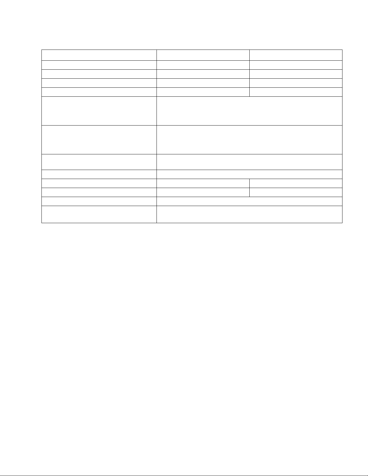
Technical Data
Pump
Maximum fluid working pressure 50 psi 0.3 MPA, 3.4 bar
Air pressure operating range 30 to 50 psi 0.2 to 0.3 MPA, 2.1 to 3.4 bar
Operating temperature (based on mechanical stress only and may be altered significantly by pumping certain chemicals.
Consult engineering guides for chemical compatibilities and temperature limits or contact your Graco distributor.
Minimum 40°F 4.4°C
Maximum 88°F 31.0°C
Maximum air consumption 28 scfm 0.672 cubic meters/min.
Maximum free flow delivery 6.5 gpm 25 lpm
Maximum pump speed 163 cpm
Gallons (Liters) per cycle 0.04 gallons 0.15 liters
Sound power level (measured per ISO standard 9614-2)
At 70 psig (0.48 MPa, 4.8 bar) at 50
cycles per minute
At 100 psig (0.7 MPa, 4 bar) at maximum
cycles per minute
Sound pressure level (measured 1 meter from pump)
At 70 psig (0.48 MPa, 4.8 bar) at 50
cycles per minute
At 100 psig (0.7 MPa, 4 bar) at maximum
cycles per minute
Air inlet size 1/4 npt(f)
Air exhaust port size 3/8 npt(f)
Fluid inlet size 1/2 and 3/4 in. bspp (f)
Fluid outlet size 1/2 and 3/4 in. bspp (f)
Wetted parts (in addition to ball, seat and diaphragm materials)
Pump Weight (approximate) 6.5 lbs 2.9 kg
System Weight (approximate) 35 lbs 15.8 kg
US Metric
77 dBa
95 dBa
67 dBa
85 dBa
polypropylene, PTFE, fluoroelastomer, SST
2
12 3A1189G
Page 13
Technical Data
Meter
US Metric
Flow range 0.5 to 15 gpm 1.9 to 57 lpm
Maximum working pressure 50 psi 0.3 MPa, 3.4 bar
Minimum working pressure 5 psi 34 MPa, 0.3 bar
Weight 1.8 lb 0.82 kg
Unit of measurement (Display shows quantity
Factory-set in quarts
in 0.01 increments up to 999.99 gallons,
quarts, pints or liters. Totalizes in gallons or
liters up to 99,999 units.)
Accuracy (At 2.5 gpm (9.5 lpm) at 70°F (21°C),
+/- 2.5% after calibration
with water and 1 gallon dispensed. May
require calibration; out-of-box accuracy is +/5%)
Repeatability (At 2.5 gpm (9.5 lpm), at 70°F
+/- 0.15%
(21°C), with water and 1 gallon dispensed.)
Inlet and outlet 1/2 bspp
Operating temperature range -4°F to 122°F -25°C to 50°C
Storage temperature range -13°F ti 122°F -25°C to 50°C
Wetted parts SST, nickel, fluoroelastomer
Batteries (Recommended batteries: Dura-
®
, Energizer®, Eveready®, EN22®)
cell
®
Duracell
Eveready
is a registered trademark of Duracell Inc.
®
and Energizer® are registered trademarks of Eveready Battery Co., Inc.
2 AA Alkaline
3A1189G 13
Page 14

Graco Standard Warranty
Graco warrants all equipment referenced in this document which is manufactured by Graco and bearing its name to be free from defects in
material and workmanship on the date of sale to the original purchaser for use. With the exception of any special, extended, or limited warranty
published by Graco, Graco will, for a period of twelve months from the date of sale, repair or replace any part of the equipment determined by
Graco to be defective. This warranty applies only when the equipment is installed, operated and maintained in accordance with Graco’s written
recommendations.
This warranty does not cover, and Graco shall not be liable for general wear and tear, or any malfunction, damage or wear caused by faulty
installation, misapplication, abrasion, corrosion, inadequate or improper maintenance, negligence, accident, tampering, or substitution of
non-Graco component parts. Nor shall Graco be liable for malfunction, damage or wear caused by the incompatibility of Graco equipment with
structures, accessories, equipment or materials not supplied by Graco, or the improper design, manufacture, installation, operation or
maintenance of structures, accessories, equipment or materials not supplied by Graco.
This warranty is conditioned upon the prepaid return of the equipment claimed to be defective to an authorized Graco distributor for verification of
the claimed defect. If the claimed defect is verified, Graco will repair or replace free of charge any defective parts. The equipment will be returned
to the original purchaser transportation prepaid. If inspection of the equipment does not disclose any defect in material or workmanship, repairs
will be made at a reasonable charge, which charges may include the costs of parts, labor, and transportation.
THIS WARRANTY IS EXCLUSIVE, AND IS IN LIEU OF ANY OTHER WARRANTIES, EXPRESS OR IMPLIED, INCLUDING BUT NOT
LIMITED TO WARRANTY OF MERCHANTABILITY OR WARRANTY OF FITNESS FOR A PARTICULAR PURPOSE.
Graco’s sole obligation and buyer’s sole remedy for any breach of warranty shall be as set forth above. The buyer agrees that no other remedy
(including, but not limited to, incidental or consequential damages for lost profits, lost sales, injury to person or property, or any other incidental or
consequential loss) shall be available. Any action for breach of warranty must be brought within two (2) years of the date of sale.
GRACO MAKES NO WARRANTY, AND DISCLAIMS ALL IMPLIED WARRANTIES OF MERCHANTABILITY AND FITNESS FOR A
PARTICULAR PURPOSE, IN CONNECTION WITH ACCESSORIES, EQUIPMENT, MATERIALS OR COMPONENTS SOLD BUT NOT
MANUFACTURED BY GRACO. These items sold, but not manufactured by Graco (such as electric motors, switches, hose, etc.), are subject to
the warranty, if any, of their manufacturer. Graco will provide purchaser with reasonable assistance in making any claim for breach of these
warranties.
In no event will Graco be liable for indirect, incidental, special or consequential damages resulting from Graco supplying equipment hereunder, or
the furnishing, performance, or use of any products or other goods sold hereto, whether due to a breach of contract, breach of warranty, the
negligence of Graco, or otherwise.
FOR GRACO CANADA CUSTOMERS
The Parties acknowledge that they have required that the present document, as well as all documents, notices and legal proceedings entered into,
given or instituted pursuant hereto or relating directly or indirectly hereto, be drawn up in English. Les parties reconnaissent avoir convenu que la
rédaction du présente document sera en Anglais, ainsi que tous documents, avis et procédures judiciaires exécutés, donnés ou intentés, à la suite
de ou en rapport, directement ou indirectement, avec les procédures concernées.
Graco Information
TO PLACE AN ORDER, contact your Graco distributor or call to identify the nearest distributor.
Phone: 612-623-6928 or Toll Free: 1-800-533-9655, Fax: 612-378-3590
All written and visual data contained in this document reflects the latest product information available at the time of publication.
Graco reserves the right to make changes at any time without notice.
Original instructions. This manual contains English. MM3A1189
For patent information, see www.graco.com/patents.
Graco Headquarters: Minneapolis
International Offices: Belgium, China, Japan, Korea
GRACO INC. P.O. BOX 1441 MINNEAPOLIS, MN 55440-1441
Copyright 2011, Graco Inc. is registered to ISO 9001
www.graco.com
February 2011, revised June 2014
 Loading...