

Page 1
Instructions
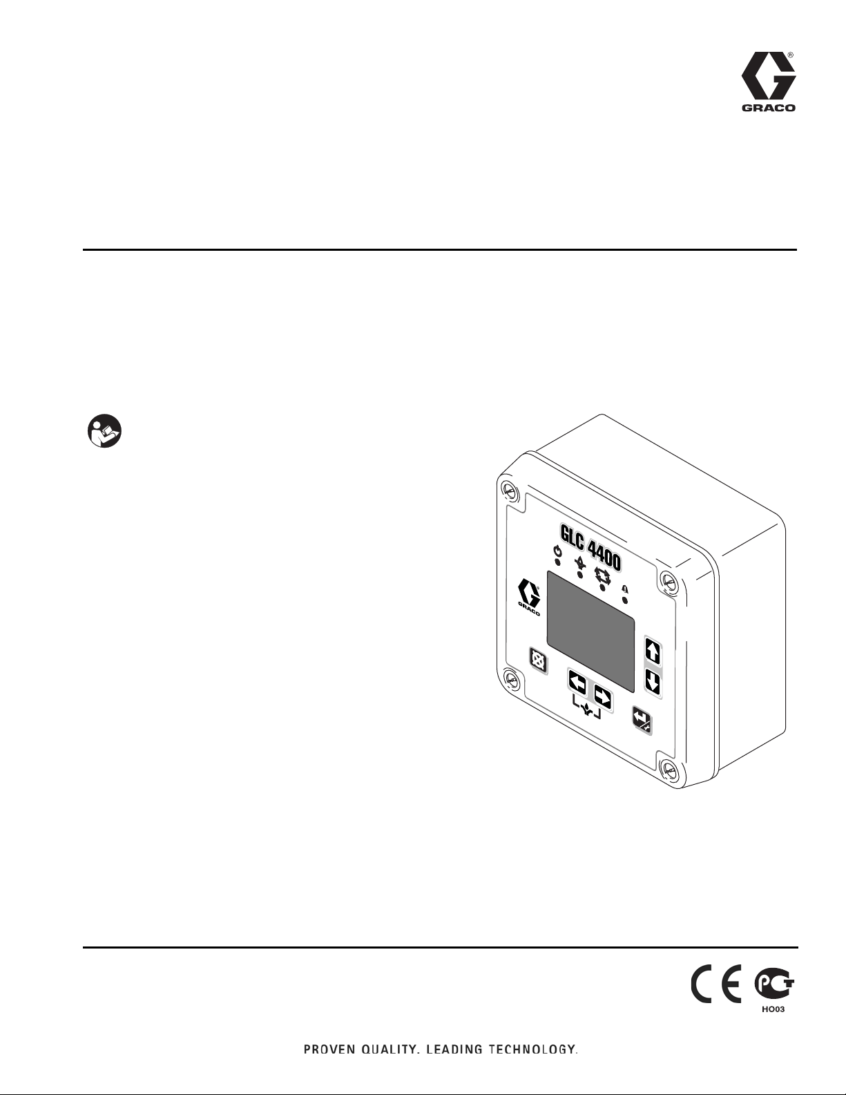
ti14059
GLC 4400
Lubrication Controller
For controlling and monitoring single-line resistive, parallel, series progressive and dual
line, automatic lubrication systems. Not for use in explosive atmospheres!
Part No.: 24B591, Series C: DC Power
Part No.: 24B596, Series C: AC Power
Important Safety Instructions
Read all warnings and instructions in this
manual. Save these instructions.
EN
313855H
Page 2

Warnings
Warnings
The following warnings are for the setup, use, grounding, maintenance, and repair of this equipment. The exclamation point symbol alerts you to a general warning and the hazard symbol refers to procedure-specific risk. Refer back
to these warnings. Additional, product-specific warnings may be found throughout the body of this manual where
applicable.
WARNING
ELECTRIC SHOCK HAZARD
This equipment must be grounded. Improper grounding, setup, or usage of the system can cause
electric shock.
• Turn off and disconnect power at main switch before disconnecting any cables and before servicing
equipment.
• Connect only to grounded power source.
• All electrical wiring must be done by a qualified electrician and comply with all local and national
codes and regulations.
EQUIPMENT MISUSE HAZARD
Misuse can cause death or serious injury.
• Do not operate the unit when fatigued or under the influence of drugs or alcohol.
• Do not exceed the maximum working pressure or temperature rating of the lowest rated system
component. See Technical Data in all equipment manuals.
• Check equipment daily. Repair or replace worn or damaged parts immediately with genuine manufacturer’s replacement parts only.
• Do not alter or modify equipment.
• Use equipment only for its intended purpose. Call your distributor for information.
• Route hoses and cables away from traffic areas, sharp edges, moving parts, and hot surfaces.
• Do not kink or over bend hoses or use hoses to pull equipment.
• Keep children and animals away from work area.
• Comply with all applicable safety regulations.
2 313855H
Page 3

Component Identification
!
A
B
C
D
E
F
Keypad, Display, and Icons
Component Identification
F
IG. 1
Run Mode Functions
Direction Arrows
A Up and Down Arrow Keys: Adjusts contrast.
B Left and Right Arrow Keys: Adjusts brightness.
• Press the LEFT and RIGHT ARROW keys
simultaneously to manually start a pump cycle.
Keypad Icons
NOTE: Keypad Icons are described on Icon’s page 4.
C ENTER Key: Press and hold for 3 seconds. Allows
access to setup.
D RESET Key: Press and hold for 3 seconds. Resets
unit to normal Pump Off state. Also is used to reset
an alarm condition.
E FUNTION LED: See page 4 for a description of
these icons.
F DISPLAY
313855H 3
Page 4
Component Identification
Icons
The following icons are used throughout this instruction manual and on the Controller’s Run and Setup Screens.
Refer to this table if you are unsure of an Icon’s meaning.
Power on indicator*. When power is supplied to the Lubrication Controller, Green LED illuminates under Function Icon
located above display screen.
Pump On indicator*. When Pump On is running, Yellow LED illuminates under Function Icon located above display
screen. Icon also is displayed on top left side of Prelube Run screens (see page 30).
Pump Off indicator. When Pump Off is running, icon is displayed on top left side of Run screens (see page 31).
Alarm event activated. LED illuminates when an Alarm event occurs. Icon also displays on top right side of Alarm
screen (see page 32).
Brightness adjustment. Use the LEFT/RIGHT Arrow key to adjust display backlight (brighter or darker) (see page 17).
Contrast adjustment. Use the UP/DOWN Arrow key to adjust screen contrast (see page 17).
Low Level Alarm. Icon appears on display screen. Indicates the lubrication fluid level is low.
Change Icon. When icon appears on PIN setup screen, indicates changes can be made to PIN number or new PIN
number can be added.
Lock Icon. Indicates the Setup screens are password protected and require the user to provide the correct PIN number
to access this feature.
Setup mode active. When user is on the Main Setup Screen in the Setup Mode, icon displays on the upper right corner
of the display screen.
Timer mode activated. Displays on right side of screen when a Timer Setup or Run screen is displayed (pages 18, 21,
30 and 31).
Pressure mode activated. Icon displays on right side screen when a Pressure Setup or Run screen is displayed (page
19 and 30).
Pressure mode error. Icon displays on alarm screen to signal the allotted time ran out before the pressure switch was
tripped.
Cycle count mode active*. Yellow LED illuminates under Function Icon located above display screen. Icon also appears
on right side of display screen when a Cycle Setup or Run screen is displayed (page 19 and 31).
Machine count active. Displays on right side of Setup or Run screen when a Machine Count screen is displayed (page
21 and 32).
Machine count error. When icon displays on alarm screen, indicates the set number of machine counts was not
received before time expired (page 32). This would trigger an alarm event.
Cycle switch input error. Icon displays in center of Alarm screen to indicate the allotted time ran out before the
programmed number of cycle switch activations was received (see Alarm Screen, page 32).
Alarm*. Red LED illuminates under symbol located above display screen. Icon also appears on display when no valid
run values have been entered.
*See Field E, page 3 for location of these Function Icons.
4 313855H
Page 5
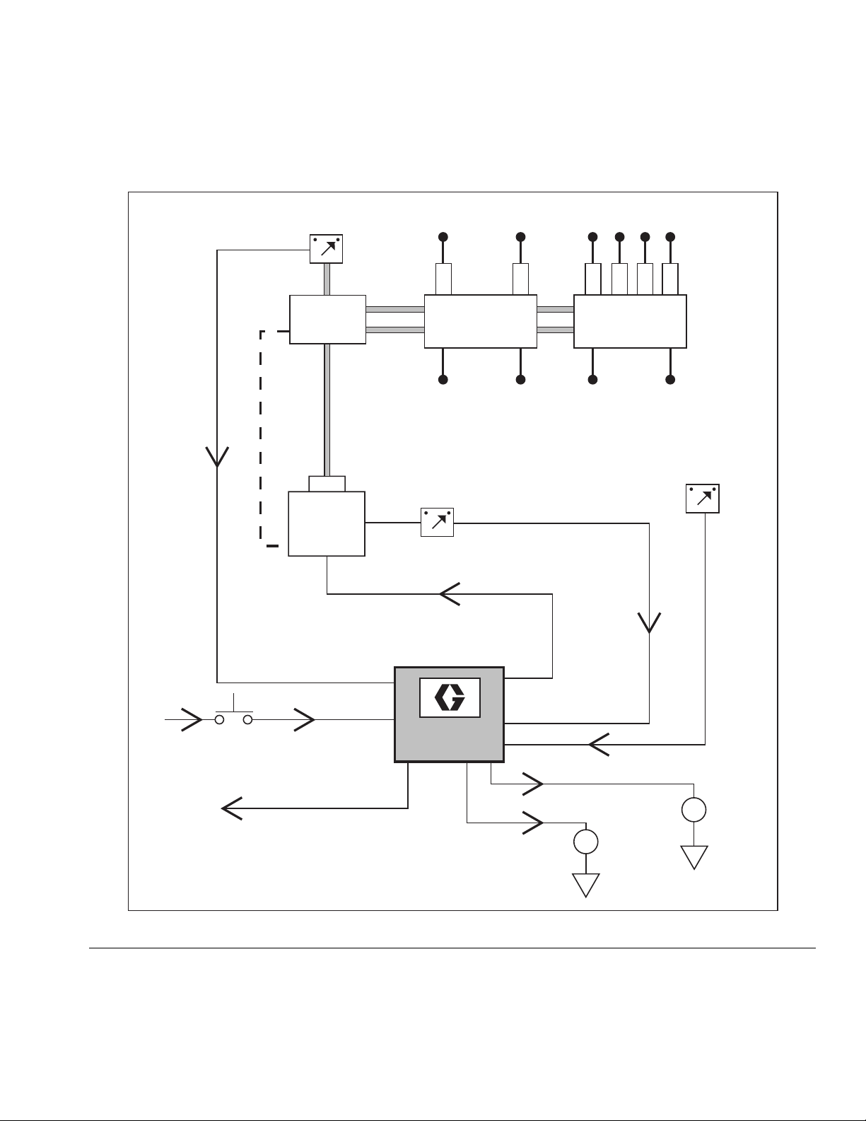
Installation
Controller
Capabilities
!
B1
B2
B3
C
E
H
G
F
D
Low Reservoir Level
switch (user provided)
Pressure or Cycle Switch
for system control
(user provided
Machine Counts for
System Control
(user provided)
Pressure Switch or Cycle
Switch Alarm
Low Level Alarm
Remote Alarm Device
(Light or Horn)
(user provided)
A
K
J
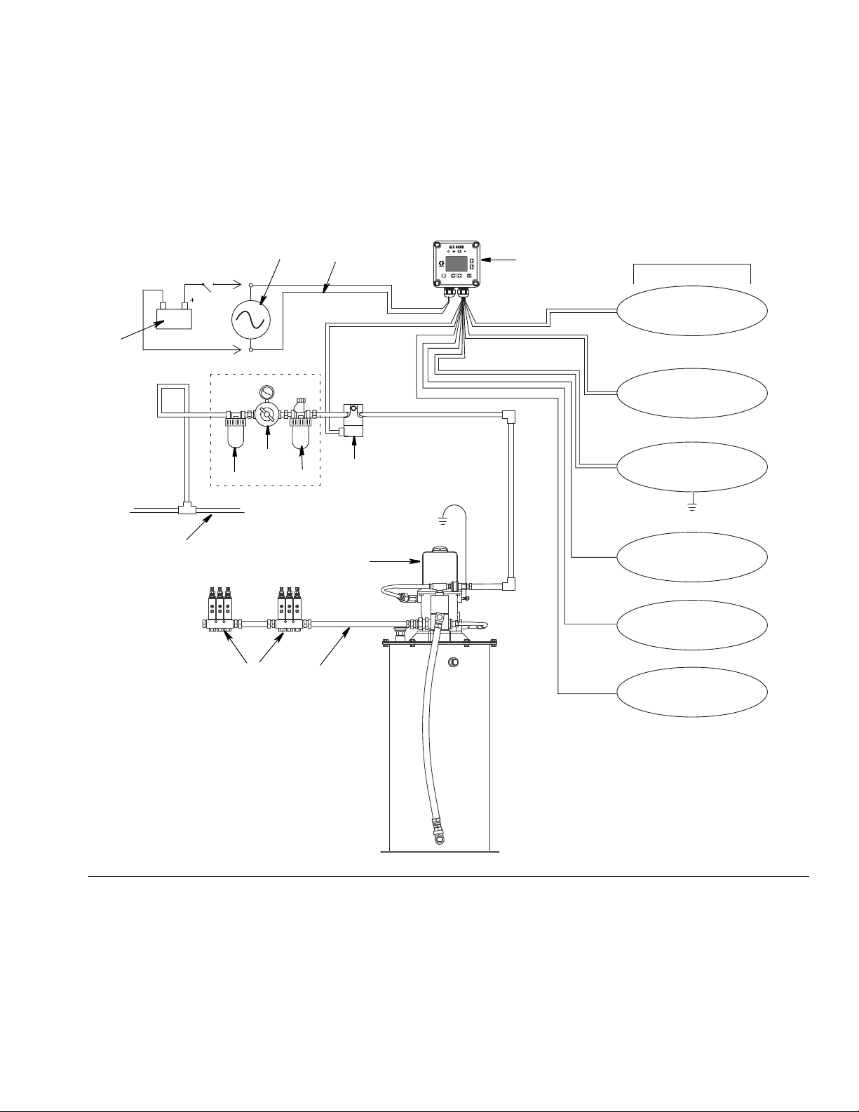
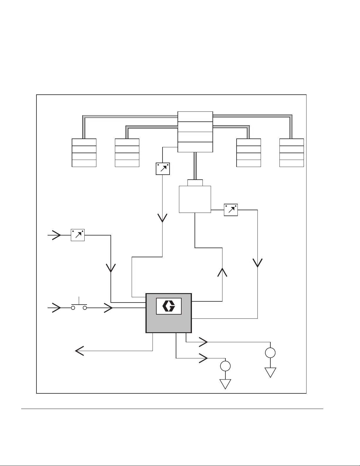
Installation
Typical Installation
The installation shown in FIG. 2 is only a guide for selecting and installing system components. Contact your Graco
distributor for assistance in planning a system to suit your needs.
FIG. 2
A Main Air Supply
B Filter/Regulator/Lubricator Assembly
B1 - Filter
B2 - Regulator
G Injector Banks
H Lubrication Controller
J Model 24B591 12/24VDC Power Supply
K Model 24B596 115/230VAC Power Supply
B3 - Lubricator
C Air Solenoid Valve
D Pump Module
E Ignition Switch
F High-Pressure Lubricant Supply Lines
313855H 5
Page 6
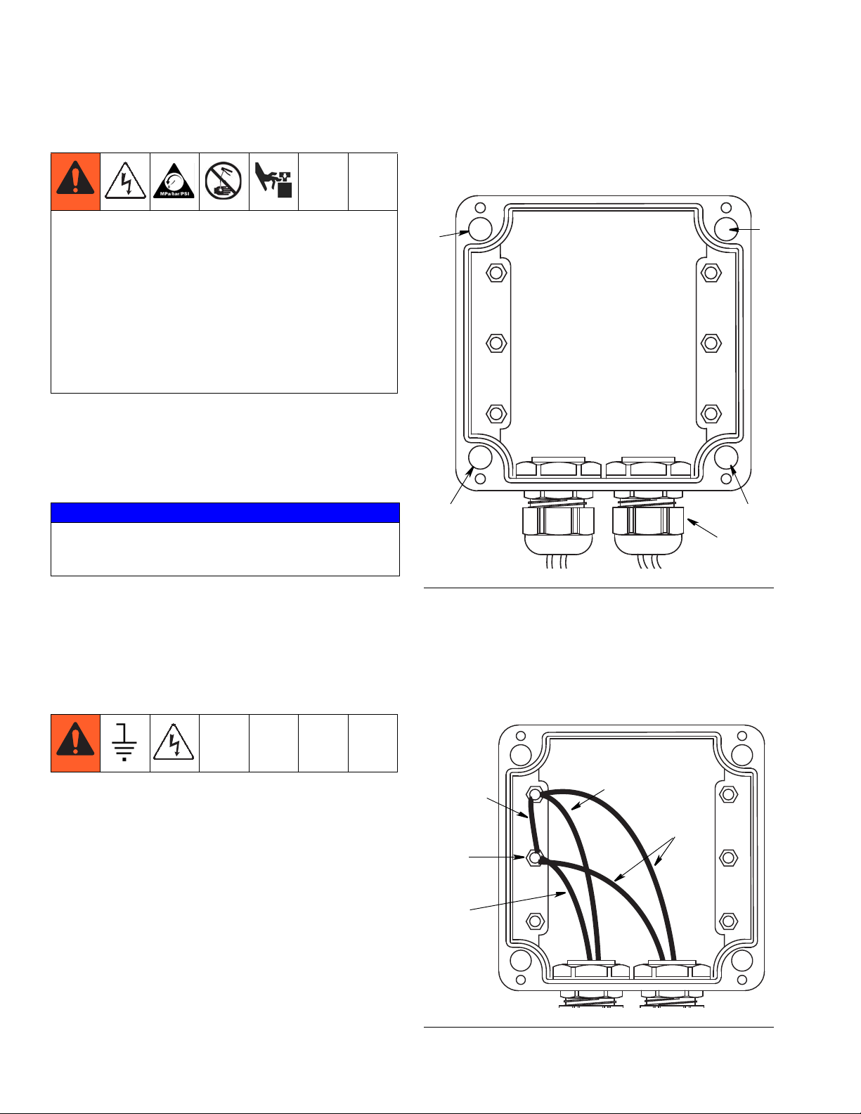
Installation
a
a
a
a
*
b
jumper
motor ground
sensor ground
ground
Installing the Lubrication Controller
AUTOMATIC SYSTEM ACTIVATION HAZARD
Unexpected activation of the system could result in serious injury, including skin injection and amputation.
This device has an automatic timer that activates the
pump lubrication system when power is connected or
when exiting the programming function. Before you
install or remove the Lubrication Controller from the
system, disconnect and isolate all power supplies and
relieve all pressure.
1. Select a flat surface to install the Lubrication Controller. Drill mounting holes. Refer to Mounting Hole
Layout provided in the Technical Data section of this
manual, page 34.
#6 screws (not provided) to secure junction box to
mounting surface.
NOTICE
Pre-drill and use designated mounting holes in Lubrication Controller box only. Failure to use designated
mounting holes can cause circuit board damage.
2. Remove Lubrication Controller cover and align junction box with predrilled holes (F
IG. 3, (a). Use four,
Grounding
The equipment must be grounded. Grounding reduces
the risk of static and electric shock by providing an
escape wire for the electrical current due to static build
up or in the event of a short circuit.
1. Loosen M6 screws from (b).
2. Attach up to 3 ground wires to (b) using appropriate
sized M6 ring terminal (not provided).
FIG. 3
* Parts not supplied. To maintain IP69K rating, proper
connectors must be used.
3. If more than 3 wires are used, attach necessary
amount of jumpers to other adjacent screw terminals.
FIG. 4
6 313855H
Page 7
Installation
System Configuration and Wiring
The System Configuration Diagrams (FIG. 5 - FIG. 7), Sensor Wiring Diagrams (FIG. 8 - FIG. 10) and Wiring Diagrams
(F
IG. 11 - FIG. 16) on the following pages, show typical Injector, Divider Valve and Dual Line lubrication system config-
urations.
Refer to Table 1, 2 and 3 to determine the Required System Configuration, Sensor Configuration and Wiring Diagram
to use to setup your system.
Table 4 shows additional (optional) setup configurations (F
Table 1: System Configurations
System Figure Page
Divider Valve 5 8
Dual Line 6 9
Injector 7 10
Table 2: Sensor Wiring Configurations
Sensor Figure Page
Dry Contact 8 11
Sourcing 9 11
Sinking 10 11
IG. 17 - FIG. 19).
Table 3: Modes of Operation
Mode Power Figure Page
Time ON/Time OFF DC 11 12
Time ON/Time OFF AC 12 12
Cycle ON or Pressure
ON/Time OFF
Cycle ON or Pressure
ON/Time OFF
Cycle ON or Pressure
ON/Machine Count
OFF
Cycle ON or Pressure
ON/Machine Count
OFF
DC 13 13
AC 14 13
DC 15 14
AC 16 14
Table 4: Optional I/O Wiring Diagrams
System Mode Power Supply Wiring Diagram
Low Level Switch F
External Manual Run F
O.K. Contact Out F
Auxiliary and Low Level
Alarm Out
313855H 7
DC: FIG. 18, page 16
115/230 VAC: F
IG. 17, page 15
IG. 17, page 15
IG. 17, page 15
IG. 19, page 16
Page 8
Installation
GLC 4400
External
Low Level
Alarm
Remote
Manual Run
Machine
Count Switch
Low Level
Switch
Pump
Reservoir
Master Divider Valve
Secondary Divider Valves
Cycle
Switch
Divider Valve System
External O.K.
Pump On/Off
External
Alarm
Cycle
Machine
Count
System Configuration
FIG. 5
8 313855H
Page 9
GLC 4400
External
Alarm
Cycle
Machine
Count
External
Low Level
Alarm
External O.K.
Low Level
Switch
Pump
Reservoir
Dual Line System
Cycle
Switch
Bi-flo
Valves
Lubrication Points
Vent
Line
Pump On/Off
Reverser
Remote
Manual Run
Machine
Count Swtich
Installation
FIG. 6
313855H 9
Page 10

Installation
GLC 4400
External
Low Level
Alarm
Remote
Manual Run
Machine
Count Switch
Low Level
Switch
Pump
Reservoir
Injector System
Pressure
Switch
Injectors
Lubrication Points
Vent
Line
Pump On/Off
External O.K.
External
Alarm
Cycle
Machine
Count
FIG. 7
10 313855H
Page 11
Installation
x = sensor input 1,2,3 or 4
1 (SW +)
2 (IN (x))
3 (SEN (x))
4 (SW -)
J6
1 (SW +)
4 (SW -)
J6
x = sensor input 1,2,3 or 4
2 (IN (x))
3 (SEN (x))
1 (SW +)
4 (SW -)
x = sensor input 1,2,3 or 4
2 (IN (x))
3 (SEN (x))
J6
System Wiring
NOTICE
Do not connect any of the SW+ (13,9,5,1) and SW(16,12,8,4) pins together, either directly or via a
switch closure. Doing so will create a short circuit
condition which will disable and potentially damage
the controller.
NOTE: On an AC controller (p/n 24B596), the J7 strip is line (input) voltage but the J6 strip is all 24VDC. On a DC
controller (p/n 24B59‘), the J6 and J7 terminals all carry the input voltage.
Input Sensor Wiring:
DRY CONTACT SWITCH
FIG. 8
SOURCE SWITCH - 2 or 3 Wire Type
SINK SWITCH - 2 or 3 Wire Type
FIG. 10
IG. 9
F
313855H 11
Page 12

Installation
16 (SW-)
15 (SEN4)
14 (IN4)
13 (SW+)
12 (SW-)
11 (SEN3)
10 (IN3)
9 (SW+)
8 (SW-)
7 (SEN2)
6 (IN2)
5 (SW+)
4 (SW-)
3 (SEN1)
2 (IN1)
1 (SW+)
1(IN)
2(COM)
3(OUT1)
4(COM)
5(OUT2)
6(COM)
7(OUT3)
8(COM)
9(OUT4)
10(OUT4)
11
OUTPUTS
-PWR+
J6J7
Air Solenoid
+
+
(Voltage = Battery Voltage)
Pump Solenoid
Ignition Switch
9 - 30 VDC Battery
Manual
Low
Level
Press/
Cycle
Count
5A max.
NC
16 (SW-)
15 (SEN4)
14 (IN4)
13 (SW+)
12 (SW-)
11 (SEN3)
10 (IN3)
9 (SW+)
8 (SW-)
7 (SEN2)
6 (IN2)
5 (SW+)
4 (SW-)
3 (SEN1)
2 (IN1)
1 (SW+)
1(IN)
2(COM)
3(OUT1)
4(COM)
5(OUT2)
6(COM)
7(OUT3)
8(COM)
9(OUT4)
10(OUT4)
11
OUTPUTS
-PWR+
J6J7
Air Solenoid
Ignition Switch
Manual
Low
Level
Press/
Cycle
Count
100-240 VAC
(Voltage = Line Voltage)
Pump Solenoid
10A max.
NC
Pump ON = Time; Pump OFF = Time
9 - 30VDC
FIG. 11 *Dry Contact, FIG. 8 shown. For other configuration, see FIG. 9 or FIG. 10.
100VAC/240VAC
F
IG. 12
12 313855H
Page 13

System Wiring
16 (SW-)
15 (SEN4)
14 (IN4)
13 (SW+)
12 (SW-)
11 (SEN3)
10 (IN3)
9 (SW+)
8 (SW-)
7 (SEN2)
6 (IN2)
5 (SW+)
4 (SW-)
3 (SEN1)
2 (IN1)
1 (SW+)
1(IN)
2(COM)
3(OUT1)
4(COM)
5(OUT2)
6(COM)
7(OUT3)
8(COM)
9(OUT4)
10(OUT4)
11
OUTPUTS
-PWR+
J6J7
Air or Hydraulic Solenoid
Pump Power or Motor
+
+
Ignition Switch
Manual
Low
Level
Press/
Cycle
Count
(Voltage = Battery Voltage)
Pump Solenoid
9 - 30 VDC Battery
Dry Contact Switch
*
5A max.
NC
Electric Vent Valve
10A max.
16 (SW-)
15 (SEN4)
14 (IN4)
13 (SW+)
12 (SW-)
11 (SEN3)
10 (IN3)
9 (SW+)
8 (SW-)
7 (SEN2)
6 (IN2)
5 (SW+)
4 (SW-)
3 (SEN1)
2 (IN1)
1 (SW+)
1(IN)
2(COM)
3(OUT1)
4(COM)
5(OUT2)
6(COM)
7(OUT3)
8(COM)
9(OUT4)
10(OUT4)
11
OUTPUTS
-PWR+
J6J7
Ignition Switch
Manual
Low
Level
Press/
Cycle
Count
100-240 VAC
(Voltage = Line Voltage)
Pump Solenoid
Dry Contact Switch
*
NC
Air or Hydraulic Solenoid
Pump Power or Motor
Electric Vent Valve
Pump ON = Cycle or Pressure; Pump OFF = Time
9 - 30VDC
Installation
FIG. 13 *Dry Contact, FIG. 8 shown. For other configuration, see FIG. 9 or FIG. 10.
100VAC/240VAC
F
IG. 14 *Dry Contact, FIG. 8 shown. For other configuration, see FIG. 9 or FIG. 10.
313855H 13
Page 14

Installation
5A max.
16 (SW-)
15 (SEN4)
14 (IN4)
13 (SW+)
12 (SW-)
11 (SEN3)
10 (IN3)
9 (SW+)
8 (SW-)
7 (SEN2)
6 (IN2)
5 (SW+)
4 (SW-)
3 (SEN1)
2 (IN1)
1 (SW+)
1(IN)
2(COM)
3(OUT1)
4(COM)
5(OUT2)
6(COM)
7(OUT3)
8(COM)
9(OUT4)
10(OUT4)
11
OUTPUTS
-PWR+
J6J7
+
Ignition Switch
Manual
Low
Level
Press/
Cycle
Count
(Voltage = Battery Voltage)
Pump Solenoid
9 - 30 VDC Battery
Dry Contact Switch
Dry Contact Switch
*
*
NC
Air or Hydraulic Solenoid
Pump Power or Motor
+
Electric Vent Valve
10A max.
16 (SW-)
15 (SEN4)
14 (IN4)
13 (SW+)
12 (SW-)
11 (SEN3)
10 (IN3)
9 (SW+)
8 (SW-)
7 (SEN2)
6 (IN2)
5 (SW+)
4 (SW-)
3 (SEN1)
2 (IN1)
1 (SW+)
1(IN)
2(COM)
3(OUT1)
4(COM)
5(OUT2)
6(COM)
7(OUT3)
8(COM)
9(OUT4)
10(OUT4)
11
OUTPUTS
-PWR+
J6J7
Ignition Switch
Manual
Low
Level
Press/
Cycle
Count
100-240 VAC
(Voltage = Line Voltage)
Pump Solenoid
Dry Contact Switch
Dry Contact Switch
*
*
NC
Air or Hydraulic Solenoid
Pump Power or Motor
Electric Vent Valve
System Wiring
Pump ON = Cycle or Pressure; Pump OFF = Machine Count
9 - 30VDC
FIG. 15 Dry Contact, FIG. 8 shown. For other configuration, see FIG. 9 or FIG. 10.
100VAC/240VAC
F
IG. 16 Dry Contact, FIG. 8 shown. For other configuration, see FIG. 9 or FIG. 10.
14 313855H
Page 15

System Wiring Options
16 (SW-)
15 (SEN4)
14 (IN4)
13 (SW+)
12 (SW-)
11 (SEN3)
10 (IN3)
9 (SW+)
8 (SW-)
7 (SEN2)
6 (IN2)
5 (SW+)
4 (SW-)
3 (SEN1)
2 (IN1)
1 (SW+)
1(IN)
2(COM)
3(OUT1)
4(COM)
5(OUT2)
6(COM)
7(OUT3)
8(COM)
9(OUT4)
10(OUT4)
11
OUTPUTS
-PWR+
J6J7
Manual
Low
Level
Press/
Cycle
Count
O.K. Contact
(Closed = O.K.)
Dry Contact Switch
Dry Contact Switch
*
*
NC
NOTICE
Do not connect any of the SW+ (13,9,5,1) and SW(16,12,8,4) pins together, either directly or via a
switch closure. Doing so will create a short circuit
condition which will disable and potentially damage
the controller.
All Units: Low Level Switch / External Manual Run / O.K. Contact Out
Installation
FIG. 17 Dry Contact, FIG. 8 shown. For other configuration, see FIG. 9 or FIG. 10.
313855H 15
Page 16

Installation
16 (SW-)
15 (SEN4)
14 (IN4)
13 (SW+)
12 (SW-)
11 (SEN3)
10 (IN3)
9 (SW+)
8 (SW-)
7 (SEN2)
6 (IN2)
5 (SW+)
4 (SW-)
3 (SEN1)
2 (IN1)
1 (SW+)
1(IN)
2(COM)
3(OUT1)
4(COM)
5(OUT2)
6(COM)
7(OUT3)
8(COM)
9(OUT4)
10(OUT4)
11
OUTPUTS
-PWR+
J6J7
+
Alarm
Alarm +9-30V
1 Amp Max
1 A Fuse
+
Low
Level
Alarm +9-30V
1 Amp Max
1 A Fuse
Manual
Low
Level
Press/
Cycle
Count
Aux (cycle, pressure, machine count)
NC
16 (SW-)
15 (SEN4)
14 (IN4)
13 (SW+)
12 (SW-)
11 (SEN3)
10 (IN3)
9 (SW+)
8 (SW-)
7 (SEN2)
6 (IN2)
5 (SW+)
4 (SW-)
3 (SEN1)
2 (IN1)
1 (SW+)
1(IN)
2(COM)
3(OUT1)
4(COM)
5(OUT2)
6(COM)
7(OUT3)
8(COM)
9(OUT4)
10(OUT4)
11
OUTPUTS
-PWR+
J6J7
Alarm
Alarm 100-240 VAC
1 Amp Max
1 A Fuse
Low
Level
1 A Fuse
Manual
Low
Level
Press/
Cycle
Count
Aux (cycle, pressure, machine count)
Alarm 100-240 VAC
1 Amp Max
NC
System Wiring Options: Alarm Out
9 - 30VDC
FIG. 18
100/240VAC
F
IG. 19
16 313855H
Page 17
Setup
C
D
A
B
Setup
System Setup - PIN Mode Enabled
See Electric Connection Warning, page 7.
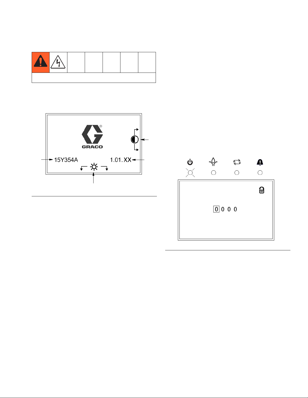
When you first turn on power to the Lubrication Controller, the following identification screen displays.
F
IG. 20
A Display Contrast Adjustment: UP and DOWN
Arrows can be used to adjust the display contrast.
1. To access Setup Mode, hold down the ENTER key
for 3 seconds. The PIN ModeScreen shown in F
21 displays.
NOTE:
• The Pin Mode screen shown in F
when the PIN mode is enabled. For setting up systems when the PIN mode is not enabled, go to System Setup instructions on page 18.
• Before the PIN Mode screen shown in F
display, the PIN Mode must be enabled in an previous setup sequence. See PIN Setup, page 25.
IG. 21 only displays
IG. 21 can
IG.
B Brightness Adjustment: LEFT and RIGHT Arrows
can be used to adjust the backlight brightness.
NOTE: Contrast and Brightness adjustments can be
made on any Run Screen at any time.
C Software (Part Number): 15Y354
D (Software) Version: 1.01.XX
NOTE: The example of the Software Version (D) shown
in F
IG. 20 displays “XX” as the last two numerals. On
your Controller’s screen, the “XX” will be replaced by the
current software version numbers.
FIG. 21
2. The PIN Mode screen in F
NOTE: The PIN Code prompt spaces are initially blank.
3. Use the LEFT / RIGHT arrow to position the cursor
over the first blank PIN Code prompt field (F
4. Use the UP/DOWN arrows to move up and down
through the numbers 0-9 until the first number in the
PIN code is displayed in the field.
5. Use the RIGHT arrow to move the cursor to the next
field.
6. Repeat steps 4 and 5 for each PIN Code prompt
field.
7. When finished, press ENTER.
IG. 21 displays.
IG. 21).
313855H 17
Page 18

Setup
8. If the PIN Code you entered is correct, the System
Setup Screen, shown in F
9. If the PIN Code you entered is incorrect, the digits
flash. The Code must be re-entered by repeating
steps 4 and 5.
NOTE:
• As soon as any arrow key is pressed, the numerals
stop flashing.
• To leave any Setup Screen and return to normal
operation, press RESET.
IG. 22 displays.
FIG. 23
System Setup
Main Screen
F
IG. 22
1. Use the UP/DOWN arrows to move the cursor up
and down through the list of setup screens (F
2. Press ENTER to display the selected setup screen.
3. When all setup operations are complete, press
RESET to return to normal operation.
IG. 22).
1. Use the UP/DOWN Arrow keys to move the cursor
over PUMP ON.
2. Press ENTER to display the PUMP ON setup
screen.
TIMER Setup
IG. 24
F
NOTE: Time is displayed in HH:MM:SS.
1. Use the Arrow keys to move the cursor over the
PUMP ON time box.
PUMP ON Setup
Pump On is the length of time the pump runs before its
cycle is terminated by either a timer, a specific number
of cycles or a certain pressure threshold is attained.
18 313855H
2. Press ENTER.
3. Use the UP/DOWN arrows to move up and down
through the numbers 0-9 until the first number in the
PUMP ON time is displayed in the field.
4. Use the RIGHT arrow to move the cursor to the next
field.
5. Repeat steps 3 and 4 until the desired time is displayed.
6. Use the Arrow keys to move the cursor over the
ENDED BY pull-down list.
Page 19

Setup
7. Press ENTER.
8. Select TIMER from the pull-down list.
9. Press RESET. The Main Screen displays.
NOTE: When TIMER is selected, the Timer Icon will display on the top right corner of the screen.
PRESSURE Setup
F
IG. 25
NOTE: Time is displayed in HH:MM:SS.
CYCLE END Setup
FIG. 26
NOTE: Time is displayed in HH:MM:SS.
1. Use the Arrow keys to move the cursor over the
PUMP ON time box.
2. Press ENTER.
3. Use the UP/DOWN arrows to move up and down
through the numbers 0-9 until the first number in the
PUMP ON time is displayed in the field.
1. Use the Arrow keys to move the cursor over the
PUMP ON time box.
2. Press ENTER.
3. Use the UP/DOWN arrows to move up and down
through the numbers 0-9 until the first number in the
PUMP ON time is displayed in the field.
4. Use the RIGHT arrow to move the cursor to the next
field.
5. Repeat steps 3 and 4 until the desired time is displayed.
6. Use the Arrow keys to move the cursor over the
ENDED BY pull-down list.
7. Press ENTER.
8. Select PRESSURE from the pull-down list.
9. Press RESET. The Main Screen, page 18 displays.
NOTE: When PRESSURE is selected, the Pressure
Icon will display on the top right corner of the screen.
4. Use the RIGHT arrow to move the cursor to the next
field.
5. Repeat steps 3 and 4 until the desired time is displayed.
6. Use the Arrow keys to move the cursor over the
ENDED BY pull-down list.
7. Press ENTER.
8. Select CYCLE from the pull-down list.
9. Press ENTER.
313855H 19
Page 20

Setup
Cycle Mode Selection
If the Cycle Mode is selected you will also be prompted
to set the desired number of cycles.
NOTE: A cycle is equal to two switch closure transitions
at the cycle switch input.
F
IG. 27
10. Use the Arrow keys to move the cursor over the
CYCLES field.
PUMP OFF Setup
Sets up how the PUMP OFF cycle is ended: Time,
Machine Count switch activation, or Machine Count activations limited by a maximum time.
FIG. 28
1. Use the UP/DOWN Arrow keys to move the cursor
over PUMP OFF.
2. Press ENTER to display the PUMP OFF setup
screen.
11. Press ENTER.
12. Use the UP/DOWN arrows to move up and down
through the numbers 0-9 until the first number you
want in the CYCLES field is displayed.
13. Use the RIGHT arrow to move the cursor to the next
field. Repeat step 12.
NOTE: The maximum number of Cycles you can setup
in this field is 99.
14. Press RESET. The Main Screen, page 18 displays.
NOTE: When Cycles is selected, the Cycles Icon displays is the upper right corner of the screen.
To Set the Pump OFF Option
F
IG. 29
1. Use the Arrow keys to move the cursor over the
PUMP OFF pull-down menu.
2. Press ENTER.
3. Use the UP/DOWN Arrow keys to move cursor to
select TIME, COUNT or BOTH.
4. After you make your selection, Press ENTER.
20 313855H
Page 21

Setup
If TIME is selected:
If TIME is selected you will also be prompted to set the
specific amount of time.
F
IG. 30
1. Use the Arrow keys to move the cursor over the
TIME field.
2. Press ENTER.
NOTE: Time is displayed in HH:MM:SS.
1. Use the Arrow keys to move the cursor over the
COUNTS field.
2. Press ENTER.
3. Use the UP/DOWN arrows to move up and down
through the numbers 0-9 until the first number you
want in the COUNTS field is displayed.
4. Use the RIGHT arrow to move the cursor to the next
field. Repeat step 3.
NOTE: The maximum number of Counts you can setup
in this field is 9999.
5. Press RESET. The Main Screen, page 18 displays.
If BOTH is selected:
If PUMP OFF is set to BOTH, the GLC 4400 will stay in
the PUMP OFF state until the entered number of
machine counts is received or the time expires.
If TIMEOUT is set to FAULT, an alarm will occur when
the time expires.
3. Use the UP/DOWN arrows to move up and down
through the numbers 0-9 until the first number in the
pump off TIME is displayed in the field.
4. Use the RIGHT arrow to move the cursor to the next
field.
5. Repeat steps 3 and 4 until the desired time is displayed.
6. Press RESET. The Main Screen, page 18 displays.
If COUNT is selected:
If COUNT is selected you will also be prompted to set
the specific number of counts.
If TIMEOUT is set to RUN, the unit will enter PUMP ON
when time expires.
If BOTH is selected you will be prompted to set the specific amount of time and determine what occurs when
time expires.
FIG. 32
1. Use the Arrow keys to move the cursor over the
COUNTS field.
2. Press ENTER.
3. Use the UP/DOWN arrows to move up and down
through the numbers 0-9 until the first number you
F
IG. 31
313855H 21
want in the COUNTS field is displayed.
Page 22

Setup
4. Use the RIGHT arrow to move the cursor to the next
field. Repeat step 3.
NOTE: The maximum number of Counts you can setup
in this field is 9999.
5. Use the Arrow keys to move the cursor over the
TIME field.
6. Press ENTER.
NOTE: Time is displayed in HH:MM:SS.
7. Use the UP/DOWN arrows to move up and down
through the numbers 0-9 until the first number in the
PUMP OFF time is displayed in the field.
8. Use the RIGHT arrow to move the cursor to the next
field. Repeat step 7.
9. Repeat steps 7 and 8 until the desired time is displayed.
10. Press ENTER.
11. Use the Arrow keys to move the cursor over the
TIMEOUT pull-down menu.
POWER UP Setup
FIG. 34
1. Use the UP/DOWN Arrow keys to move the cursor
over POWER UP.
2. Press ENTER to display the POWER UP setup
screen.
Power Up can be programmed one of four ways:
First: At Power Up, the normal lube cycle that was in
process when power was removed, is resumed.
F
IG. 35
F
IG. 33
1. Use the Arrow keys to move the cursor over the
POWER UP pull-down menu.
12. Press ENTER.
2. From the pull-down menu, select OFF.
13. When time expires:
3. Press ENTER.
• Select FAULT if an alarm should occur.
• Select RUN if unit should enter PUMP ON.
4. Use the Arrow keys to move the cursor over the
DELAY pull-down menu.
14. Press ENTER.
5. From the pull-down menu, select OFF.
15. Press RESET. The Main Screen, page 18 displays.
6. Press RESET. The Main Screen, page 18 displays.
NOTE: If Count or Both is selected, the Count Icon displays in the upper right corner of the screen.
22 313855H
Page 23

Setup
Second: At Power Up, a delay occurs, the pump is off;
then the normal lube cycle that was in process when
power was removed, is resumed.
F
IG. 36
1. Use the Arrow keys to move the cursor over the
POWER UP pull-down menu.
2. From the pull-down menu, select OFF.
3. Press ENTER.
4. Use the Arrow keys to move the cursor over the
DELAY pull-down menu.
5. From the pull-down menu, select ON.
6. Press ENTER.
7. Use the Arrow keys to move the cursor over the
DELAY TIME field.
Third: At Power Up, immediately go to PUMP ON
(normal on time)..
FIG. 37
1. Use the Arrow keys to move the cursor over the
POWER UP pull-down menu.
2. From the pull-down menu, select ON.
3. Press ENTER.
4. Use the Arrow keys to move the cursor over the
DELAY pull-down menu.
5. From the pull-down menu, select OFF.
6. Press RESET. The Main Screen, page 18 displays.
Fourth: At Power Up, go to programmed PUMP OFF
delay time; then to normal PUMP ON.
8. Press ENTER.
NOTE: Time is displayed in MM:SS.
9. Use the UP/DOWN arrows to move up and down
through the numbers 0-9 until the first number in the
DELAY TIME is displayed in the field.
10. Use the RIGHT arrow to move the cursor to the next
field. Repeat step 9.
F
11. Repeat steps 9 and 10 until the desired time is dis-
IG. 38
played.
12. Press RESET. The Main Screen, page 18 displays.
1. Use the Arrow keys to move the cursor over the
POWER UP pull-down menu.
2. From the pull-down menu, select ON.
3. Press ENTER.
4. Use the Arrow keys to move the cursor over the
DELAY pull-down menu.
313855H 23
Page 24

Setup
5. From the pull-down menu, select ON.
6. Press ENTER.
7. Use the Arrow keys to move the cursor over the
DELAY TIME field.
8. Press ENTER.
NOTE: Time is displayed in MM:SS.
9. Use the UP/DOWN arrows to move up and down
through the numbers 0-9 until the first number in the
DELAY TIME is displayed in the field.
10. Use the RIGHT arrow to move the cursor to the next
field. Repeat step 9.
11. Repeat steps 9 and 10 until the desired time is displayed.
12. Press RESET. The Main Screen, page 18 displays.
PULSED Setup
Pulsed Pump Screen
1. Use the Arrow keys to move the cursor over the
PULSE pull-down menu.
2. Press ENTER.
3. Use the UP/DOWN Arrow keys to move cursor to
select ON.
4. Press ENTER.
FIG. 41
F
IG. 39
1. Use the UP/DOWN Arrow keys to move the cursor
over PULSED.
2. Press ENTER to display the PULSED setup screen.
5. Use the Arrow keys to move the cursor over the
TIME OFF field.
6. Press ENTER.
NOTE: The time is displayed in Seconds.
7. Use the UP/DOWN arrows to move up and down
through the numbers 0-9 until the first number of the
TIME OFF you are creating is displayed in the field.
8. Use the RIGHT arrow to move the cursor to the next
field. Repeat step 7.
9. Press ENTER.
IG. 42
F
IG. 40
24 313855H
F
Page 25

Setup
10. Use the Arrow keys to move the cursor over the
TIME ON field.
11. Press ENTER.
NOTE: The time is displayed in Seconds.
12. Use the UP/DOWN arrows to move up and down
through the numbers 0-9 until the first number of the
TIME ON you are creating is displayed in the field.
13. Use the RIGHT arrow to move the cursor to the next
field. Repeat step 7.
14. Press ENTER.
15. Press RESET. The Main Screen, page 18 displays.
NOTE:
• The maximum Time Off and Time On is
99 seconds.
• The minimum Time Off is 3 seconds.
• The minimum Time On is 0 (zero) seconds.
To enable PIN Code Entry:
FIG. 44
1. Use the Arrow keys to move the cursor over the PIN
pull-down menu.
2. Press ENTER.
3. Use the UP/DOWN Arrow keys to move cursor to
select ON.
4. Press ENTER.
PIN Setup
If protection for the setup mode is desired, a PIN Code
entry can be enabled.
F
IG. 43
1. Use the UP/DOWN Arrow keys to move the cursor
over PIN CODE.
2. Press ENTER to display the PIN CODE setup
screen.
F
IG. 45
5. Use the Arrow keys to move the cursor over the PIN
CODE prompt field.
6. Use the LEFT/RIGHT arrow to position the cursor
over the first blank Pin Code prompt field (F
IG. 21).
7. Use the UP/DOWN arrows to move up and down
through the numbers 0-9 until the first number in the
PIN code you are creating is displayed in the field.
8. Use the RIGHT arrow to move the cursor to the next
field. Repeat step 7
9. Repeat steps 7 and 8 for each PIN Code prompt.
10. Press RESET. The Main Screen, page 18 displays.
313855H 25
Page 26

Setup
DISPLAY Setup
F
IG. 46
1. Use the UP/DOWN Arrow keys to move the cursor
over DISPLAY.
2. Press ENTER to display the DISPLAY setup screen.
Display Backlight
The display backlight can be set to turn off after a programmed amount of time. If the backlight is OFF it will
turn back on when any front panel key is pressed.
4. Use the Arrow keys to move the cursor over the
TIME ON field.
FIG. 48
NOTE: Time is displayed in HH:MM.
5. Use the UP/DOWN arrows to move up and down
through the numbers 0-9 until the first number in the
TIME ON is displayed in the field.
6. Use the RIGHT arrow to move the cursor to the next
field. Repeat step 5.
IG. 47
F
1. Use the Arrow keys to move the cursor over the
TIMER pull-down menu.
2. From the pull-down menu, select ON.
3. Press ENTER.
7. Repeat steps 5 and 6 until the desired time displays.
8. Press RESET. The Main Screen, page 18 displays.
QUICK CYCLE Setup
IG. 49
F
1. Use the UP/DOWN Arrow keys to move the cursor
over QUICK CYCLE.
2. Press ENTER to display the QUICK CYCLE setup
screen.
26 313855H
Page 27

Setup
Quick Cycle Screen Setup
The Quick Cycle screen setup is used to setup a Troubleshooting profile.
F
IG. 50
1. Use the Arrow keys to move the cursor over the
CYCLES field.
2. Press ENTER.
3. Use the UP/DOWN arrows to move up and down
through the numbers 0-9 until the first number you
want in the CYCLES field is displayed.
12. Repeat steps 7 - 9 for the TIME OFF field.
13. Use the Arrow keys to move the cursor over the
pull-down menu.
14. Select ON.
15. The Quick Cycle begins.
NOTE:
• The maximum Time Off and Time On is 99 seconds.
• When complete, the system returns to the Run
Mode. It does not come back to the Quick Cycle
Setup Screen.
LOW LEVEL FILTERING Setup
4. Use the RIGHT arrow to move the cursor to the next
field. Repeat step 3.
NOTE: The maximum number of Cycles you can setup
in this field is 99.
5. Use the Arrow keys to move the cursor over the
TIME ON field.
6. Press ENTER.
NOTE: Time On and Time Off in QUICK CYCLE mode
only, are displayed in Seconds.
7. Use the UP/DOWN arrows to move up and down
through the numbers 0-9 until the first number you
want to use in the TIME ON field is displayed in the
field.
8. Use the RIGHT arrow to move the cursor to the next
field. Repeat step 7.
9. Press ENTER.
10. Use the Arrow keys to move the cursor over the
TIME ON field.
FIG. 51
1. Use the UP/DOWN Arrow keys to move the cursor
over LL FILTERING.
2. Press ENTER to display the LL FILTERING setup
screen.
11. Press ENTER.
313855H 27
Page 28

Setup
Low Level Filtering Screen Setup
The Low Level Filtering screen setup is used to filter out
spurious signals from rotating paddle type low level sensors.
NOTE: When using the GLC4400 with the G3 Automatic
Lubrication Pump, it is recommended that the low level
filtering be set to G3 defaults.
The NUMBER field determines how many signal activations are required to set a fault.
The TIME field determines the amount of RUN time
required without an activation to reset the activation
count to 0 (zero).
8. Use the RIGHT arrow to move the cursor to the next
field. Repeat step 7.
9. Repeat steps 7 and 8 until the desired time is displayed.
10. Press ENTER.
11. If the default values for the G3 Automatic Lubrication Pump are intended to be used, use the
UP/DOWN arrows to move to the G3 DEFAULT
field.
12. Press ENTER. The NUMBER and TIME values will
be updated to the G3 default value.
13. Press RESET. The Main Screen, shown on page
18, displays.
F
IG. 52
1. Use the Arrow keys to move the cursor over the
NUMBER field.
2. Press ENTER.
3. Use the UP/DOWN arrows to move up and down
through the numbers 0-9 until the first number you
want in the NUMBER field is displayed.
4. Use the RIGHT arrow to move the cursor to the next
field. Repeat step 3.
NOTE: The maximum number of Counts you can setup
in this field is 99.
5. Use the Arrow keys to move the cursor over the
TIME field.
6. Press ENTER.
NOTE: Time is displayed in HH:MM:SS.
7. Use the UP/DOWN arrows to move up and down
through the numbers 0-9 until the first number in the
TIME field is displayed.
28 313855H
Page 29

Run Mode
C
D
A
B
A
B
C
D
When you first turn the Lubrication Controller power on,
the identification screen shown in F
IG. 53 displays.
Run Mode
FIG. 53
A Display Contrast Adjustment: UP and DOWN
Arrows can be used to adjust the display contrast.
B Backlight Brightness Adjustment: LEFT and
RIGHT Arrows can be used to adjust the backlight
brightness.
NOTE: Contrast and Brightness adjustments can be
made on any Run Screen at any time.
C Software (Part Number): 15Y354
D (Software) Version: 1.01.XX
Screen Identification
The following screen is only shown as an example of the
information that is displayed on a Run screen. A complete description of the icons and symbols shown in F
54 is provided on page 3.
IG.
FIG. 54
A Operating Mode Identification - Sets up Pump On/
Pump Off, page 22.
B Time Counter - Actual elapsed time counts down while
the pump runs - set up in Pump On Setup, page 18.
C Progression Bar - Real-time, visual representation of the
elapsed time the pump has been on. Runs in conjunction
with B.
D Total Pump On Time - Shows the total amount of time
the pump is on. Setup on the Pump On setup screen,
page 18.
313855H 29
Page 30

Run Mode
A
D
C
A
B
C
D
Prelube Power Up
F
IG. 55
If Prelube is enabled (page 22), the programmed prelube sequence occurs.
• The Timer icon (D) displays and indicates the Timer
Mode.
Pump On Ended with Pressure
If no Prelube sequence has been selected, the lube
cycle that was in progress at power down is resumed.
Pump On Ended with Time
F
IG. 56
If the Pump On sequence has been programmed to be
ended by TIME:
FIG. 57
If the Pump On sequence has been programmed to end
by a pressure switch:
• The GLC 4400 pump output relay activates (J7-3)
and will stay on until a switch closure is received
(J6-3) (see Setup Menus, Pump On, page 19).
• The Pump On LED (A) remains on during this time.
• The Pump On (C) icon displays.
• The Cycle LED (B) illuminates and Pressure Mode
icon (D) displays to indicate the pressure switch.
• If the pressure switch closure is not received before
time expires, an alarm occurs.
NOTE: If Pump On is ended by a pressure switch and
no Power Up delay is selected, when power to the GLC
4400 is turned on, the GLC 4400 starts at the beginning
of the Pump On time instead of resuming the Pump On
time where it left off.
• The GLC 4400 pump output relay activates (J7-3)
and will stay on until the time expires. (see Setup
Menus, Pump On, page 18).
• The Pump On LED (A) remains on during this time.
• The Pump On (C) icon displays.
30 313855H
Page 31

Run Mode
A
B
C
E
D
A
D
C
A
B
C
D
Pump On Ended with Cycle Switch
Activation
F
IG. 58
If the Pump On sequence has been programmed to end
by a Cycle Switch Activation:
• The GLC 4400 pump output relay activates (J7-3)
and will stay on until the correct number of cycle
switch closures is received (J6-3) (see Setup
Menus, Cycle End Setup page 19).
• The Pump On LED (A) remains on during this time.
• The Pump On (C) icon displays.
• The Cycle LED (B) and Cycle Count Mode icon (D)
display indicating the cycle switch is activated.
• The cycle indicator bar (E) displays a visual representation
of the cycle switch closures received.
Pump Off Ended with Time
FIG. 59
If the Pump Off sequence has been programmed to be
ended by TIME:
• The GLC 4400 pump output relay activates (J7-3)
and will stay off until the time expires. (see Setup
Menus, Pump Off, page 20).
• The Pump On LED (A) remains off during this time.
• The Pump Off icon (C) displays.
• The Timer Mode icon (D) displays and indicates the
Timer Mode.
Pump Off Ended with Machine Counts
• If the set number of cycle switch closures is not
received before time expires, an alarm occurs.
F
IG. 60
313855H 31
If the Pump Off sequence has been programmed to be
ended by MACHINE COUNTS:
Page 32

Run Mode
A
C
E
D
B
• The GLC 4400 pump output relay activates (J7-3)
and will stay off until the correct number of counts
(J6-15) occur (see Setup Menus, Pump Off, page
20).
• The Pump On LED (A) remains off during this time.
• The Pump Off icon (C) displays.
• The Cycle LED (B) and Machine Count icon (D) display and indicate the Machine Count Switch activation.
Pump Off Ended with Machine Counts; Max
Time Entered
Alarms Screen
When a cycle alarm event occurs the Alarm Screen,
shown in F
FIG. 62
To clear an alarm, hold down the Clear Key on the display Keypad (see page 3).
IG. 62 displays.
F
IG. 61
If the Pump Off sequence has been programmed to be
ended by MACHINE COUNTS with a maximum time:
• The GLC 4400 pump output relay activates (J7-3)
and will stay off until the correct number of counts
(J6-15) occur (see Setup Menus, Pump Off, page
20).
• The Pump On LED (A) remains off during this time.
• The Pump Off icon (C) displays.
• The Cycle LED (B) and Machine Count icon (D) display and indicate the Machine Count Switch activation.
• The counts indicator bar (E) displays a visual representation
of the machine counts received.
• If the set number of machine counts is not received
before time expires, an alarm occurs.
The following is a list of other alarm events that may display.
Low Level Alarm. Icon appears on display screen.
Indicates the lubrication fluid level is low.
Pressure mode error. Icon displays on alarm screen
to signal the allotted time ran out before the pressure
switch was tripped.
Machine count error. When icon displays on alarm
screen, indicates the set number of machine counts
was not received before time expired. This would
trigger an alarm event.
Cycle switch input error. Icon displays in center of
Alarm screen to indicate the allotted time ran out
before the programmed number of cycle switch
activations was received.
32 313855H
Page 33

Troubleshooting
Description Problem Solution
No power supplied to solenoid
Timer fails to activate solenoid
Solenoid faulty Replace solenoid
Timer faulty Replace timer
Low level or other alarm Refill reservoir
Pressure switch fails to shut down
system
Program Settings
Description
TIMER Setup, page 18 HH:MM:SS (00:00:01 - 99:59:59)
PRESSURE Setup, page 19 HH:MM:SS (00:00:01 - 99:59:59)
CYCLE END Setup, page 19 HH:MM:SS (00:00:01 - 99:59:59)
CYCLE MODE Selection, page 20 Cycles = 01 - 99
Pressure switch incorrectly wired Verify proper connections
Pressure switch faulty Replace pressure switch
Timer faulty Replace timer
Modes of Operation
Maximum / Minimum and Additional Comments
Time, Pressure or Cycles
Troubleshooting
Power light off: Timer is not receiving
power. Verify connections and verify
power supply.
Power light on: Verify solenoid connections
PUMP ON Setup, page 18
PUMP OFF Setup, page 20
POWER UP Setup, page 22 MM:SS (00:01 - 59:59)
PULSED Output (pump), page 24 Maximum Time OFF and Time ON: SS (01-99)
PIN Number Setup, page 25
QUICK CYCLE SCREEN Setup, page 26
PRELUBE on Power Up, page 30
Pump ON Time: HH:MM:SS (00:00:01 - 99:59:59)
Cycles: 01 - 99 (only used when mode of operation = cycles)
Time, Count or Both
Pump OFF Time: HH:MM:SS. (00:00:01 - 99:59:59)
Count: 01 - 9999
ON / OFF
0000 - 9999
Cycles = 01 - 99
Time ON and Time OFF: SS (01-99)
Execute: YES / NO
YES / NO
Delay: YES / NO
TIME: MM:SS (00:01 - 59:59)
313855H 33
Page 34

Technical Data
Technical Data
Input Contact
Power Source DC - model 24B591 9 - 30 VDC
Power Source AC - model 24B596 100 VAC to 240 VAC - 50/60 Hz
Power consumption 24 Watts
Cycle Pressure Control Input (optional) Normally open pressure or cycle switch
Machine Count Control Input (optional) Machine count control switch
Lubrication level (optional) Normally open level switch, closes upon low level
Remote Manual Run Input Normally open remote manual run switch
Outputs
Pump control Pump Control Voltage = Power Source
Voltage Power Source
Max Switching Voltage 250 VAC, 100 VDC
Max Switching Current 10 A (AC), 5A (DC)
Minimum Switching Capacity 100 mA @ 5 VDC
Low Level Alarm, normally open (optional)
Voltage Power Source
Max Switching Voltage 250 VAC, 30 VDC
Max Switching Current 5A (AC), 5A (DC)
Minimum Switching Capacity 100 mA @ 5 VDC
Auxiliary Alarm, normally open (optional)
Voltage Power Source
Max Switching Voltage 250 VAC, 30 VDC
Max Switching Current 5A (AC), 5A (DC)
Minimum Switching Capacity 100 mA @5 VDC
Status OK, normally open (optional) Voltage-free Contact
Voltage Power Source
Max Switching Voltage 250 VAC, 100 VDC
Max Switching Current 10 A (AC), 5A (DC)
Minimum Switching Capacity 100 mA @ 5 VDC
Protection grade
Enclosure Material Fiberglass reinforced polyester
Membrane Material Polyester
Bushing Ethylene Propylene Diene Monemer Rubber (EDPM)
Operating temperature range - 40°F to 145°F (- 40°C to 63°C)
Storage Temperature - 13°F to 145°F (- 25°C to 63°C)
IP69K
34 313855H
Page 35

Dimensions
4.8 in. (122 mm)
4.72 in.
(120 mm)
3.58 in.
(90.85 mm)
4.17 in.
(105.92 mm)
3.23 in.
(82.0 mm)
Dimensions Mounting Hole Layout
313855H 35
Page 36

Graco Standard Warranty
Graco warrants all equipment referenced in this document which is manufactured by Graco and bearing its name to be free from defects in
material and workmanship on the date of sale to the original purchaser for use. With the exception of any special, extended, or limited warranty
published by Graco, Graco will, for a period of twelve months from the date of sale, repair or replace any part of the equipment determined by
Graco to be defective. This warranty applies only when the equipment is installed, operated and maintained in accordance with Graco’s written
recommendations.
This warranty does not cover, and Graco shall not be liable for general wear and tear, or any malfunction, damage or wear caused by faulty
installation, misapplication, abrasion, corrosion, inadequate or improper maintenance, negligence, accident, tampering, or substitution of
non-Graco component parts. Nor shall Graco be liable for malfunction, damage or wear caused by the incompatibility of Graco equipment with
structures, accessories, equipment or materials not supplied by Graco, or the improper design, manufacture, installation, operation or
maintenance of structures, accessories, equipment or materials not supplied by Graco.
This warranty is conditioned upon the prepaid return of the equipment claimed to be defective to an authorized Graco distributor for verification of
the claimed defect. If the claimed defect is verified, Graco will repair or replace free of charge any defective parts. The equipment will be returned
to the original purchaser transportation prepaid. If inspection of the equipment does not disclose any defect in material or workmanship, repairs will
be made at a reasonable charge, which charges may include the costs of parts, labor, and transportation.
THIS WARRANTY IS EXCLUSIVE, AND IS IN LIEU OF ANY OTHER WARRANTIES, EXPRESS OR IMPLIED, INCLUDING BUT NOT LIMITED
TO WARRANTY OF MERCHANTABILITY OR WARRANTY OF FITNESS FOR A PARTICULAR PURPOSE.
Graco’s sole obligation and buyer’s sole remedy for any breach of warranty shall be as set forth above. The buyer agrees that no other remedy
(including, but not limited to, incidental or consequential damages for lost profits, lost sales, injury to person or property, or any other incidental or
consequential loss) shall be available. Any action for breach of warranty must be brought within two (2) years of the date of sale.
GRACO MAKES NO WARRANTY, AND DISCLAIMS ALL IMPLIED WARRANTIES OF MERCHANTABILITY AND FITNESS FOR A
PARTICULAR PURPOSE, IN CONNECTION WITH ACCESSORIES, EQUIPMENT, MATERIALS OR COMPONENTS SOLD BUT NOT
MANUFACTURED BY GRACO. These items sold, but not manufactured by Graco (such as electric motors, switches, hose, etc.), are subject to
the warranty, if any, of their manufacturer. Graco will provide purchaser with reasonable assistance in making any claim for breach of these
warranties.
In no event will Graco be liable for indirect, incidental, special or consequential damages resulting from Graco supplying equipment hereunder, or
the furnishing, performance, or use of any products or other goods sold hereto, whether due to a breach of contract, breach of warranty, the
negligence of Graco, or otherwise.
FOR GRACO CANADA CUSTOMERS
The Parties acknowledge that they have required that the present document, as well as all documents, notices and legal proceedings entered into,
given or instituted pursuant hereto or relating directly or indirectly hereto, be drawn up in English. Les parties reconnaissent avoir convenu que la
rédaction du présente document sera en Anglais, ainsi que tous documents, avis et procédures judiciaires exécutés, donnés ou intentés, à la suite
de ou en rapport, directement ou indirectement, avec les procédures concernées.
Graco Information
For the latest information about Graco products, visit www.graco.com.
TO PLACE AN ORDER, contact your Graco distributor or call to identify the nearest distributor.
Phone: 612-623-6928 or Toll Free: 1-800-533-9655, Fax: 612-378-3590
All written and visual data contained in this document reflects the latest product information available at the time of publication.
GRACO INC. AND SUBSIDIARIES • P.O. BOX 1441 • MINNEAPOLIS MN 55440-1441 • USA
Copyright 2009, Graco Inc. All Graco manufacturing locations are registered to ISO 9001.
Graco reserves the right to make changes at any time without notice.
For patent information, see www.graco.com/patents.
Original instructions. This manual contains English. MM 313855
Graco Headquarters: Minneapolis
International Offices: Belgium, China, Japan, Korea
www.graco.com
Revised December 2013
 Loading...