

Page 1
Instruction Manual
RF Signal Tester
Part No. 249269, Series A, North America (N.A.)
Part No. 249880, Series A, Australia
Used to evaluate the Matrix RF signal quality in a new or existing Matrix facility.
Important Safety Instructions
Read all warnings and instructions in this
manual. Save these instructions.
311002C
EN
FCC ID: JHIGNET
IC: 4840AGNET
Industry Canada Statement
The term “IC” before the certification/registration number only signifies that the
Industry Canada technical specifications
were met.
Graco Inc. P.O. Box 1441 Minneapolis, MN 55440-1441
Copyright 2005, Graco Inc. is registered to I.S. EN ISO 9001
✓
C
LISTED
TI6745A
Australian Vendor Code: N3845
US
Page 2

Contents
Manual Conventions
Manual Conventions . . . . . . . . . . . . . . . . . . . . . . . . 2
Warnings . . . . . . . . . . . . . . . . . . . . . . . . . . . . . . . . . 3
Overview . . . . . . . . . . . . . . . . . . . . . . . . . . . . . . . . . . 4
Removing and Replacing the Battery . . . . . . . . . . 4
Display Functions . . . . . . . . . . . . . . . . . . . . . . . . . . 5
Asleep / Awake Mode . . . . . . . . . . . . . . . . . . . . . 5
Battery Life Indicator . . . . . . . . . . . . . . . . . . . . . . 5
Operation . . . . . . . . . . . . . . . . . . . . . . . . . . . . . . . . . 5
Preliminary Settings . . . . . . . . . . . . . . . . . . . . . . 5
Select Network and Transceiver ID . . . . . . . . . . . 6
Performing the RF Signal Test . . . . . . . . . . . . . . 6
Optional Display Information . . . . . . . . . . . . . . . . 7
Determining Transceiver Dipswitch Settings . . . . 8
Dipswitch Setting using RS422 Connection . . . . 9
Parts for 249269 and 249880 Matrix RF Signal Tester
10
Technical Specifications . . . . . . . . . . . . . . . . . . . . 11
Dimensions . . . . . . . . . . . . . . . . . . . . . . . . . . . . . . . 11
Graco Standard Warranty . . . . . . . . . . . . . . . . . . . 12
Graco Phone Numbers . . . . . . . . . . . . . . . . . . . . . 12
Manual Conventions
Warning Caution
WARNING
CAUTION indicates a potentially hazardous situation
which, if not avoided, may result in property damage or
WARNING indicates a potentially hazardous situation
which, if not avoided, could result in death or serious
injury.
destruction of equipment.
Note
A note indicates additional helpful information.
CAUTION
2 311002C
Page 3

Warnings
Warnings
The following general warnings are related to the safe setup, use, grounding, maintenance and repair of this equipment. Additional more specific warnings may be found throughout the text of this manual where applicable.
WARNING
FIRE AND EXPLOSION HAZARD
When flammable fluids are present in the work area, such as gasoline and windshield wiper fluid, be
aware that flammable fumes can ignite or explode. To help prevent fire and explosion:
• Use equipment only in well ventilated area.
• Eliminate all ignition sources, such as cigarettes and portable electric lamps.
• Keep work area free of debris, including rags and spilled or open containers of solvent and gasoline.
• Do not plug or unplug power cords or turn lights on or off when flammable fumes are present.
• Ground equipment.
• Use only grounded hoses.
• If there is static sparking or you feel a shock, stop operation immediately. Do not use equipment
until you identify and correct the problem.
• Keep a fire extinguisher in the work area.
BATTERY SAFETY
The battery may leak, explode, cause burns, or cause an explosion if mishandled:
• You must use the battery type specified for use with the equipment.
• Sparking can occur when changing batteries. Only replace the battery in a non-hazardous location,
away from flammable fluids or fumes.
• Handle and dispose of battery properly - do not short circuit, charge, force over discharge, disassemble, crush, penetrate, incinerate, or heat the battery to a temperature exceeding 185° F (85° C).
311002C 3
Page 4
Overview
Overview
The Matrix RF Signal Tester is used to evaluate the
Matrix RF signal quality for locating the Transceiver(s) in
a new or existing Matrix facility.
The quality of Matrix RF signals can be affected by
building characteristics such as building size and type of
construction. Other RF devices located in the building or
close by can also interfere with Matrix RF signals. The
RF Signal Tester will assist you in positioning the Matrix
Transceiver(s) in the best possible location.
The RF Signal Tester is battery powered and contains
RF hardware identical to that used in Matrix Meters and
Tank Level Monitors (TLMs).
The RF Signal Tester requires a Matrix Transceiver
to function properly. The Transceiver must be posi-
tioned in the building as close as possible to the position
of intended installation. The Transceiver must be powered up, but does not need to be connected to a PC.
If the facility already has a functioning Matrix system,
the RF Signal Tester can utilize the existing Transceiver
without interrupting or interfering with the Matrix system.
A second “test” Transceiver can still be used, if desired,
as long as its dip switch settings are not already in use
by another Transceiver in the facility.
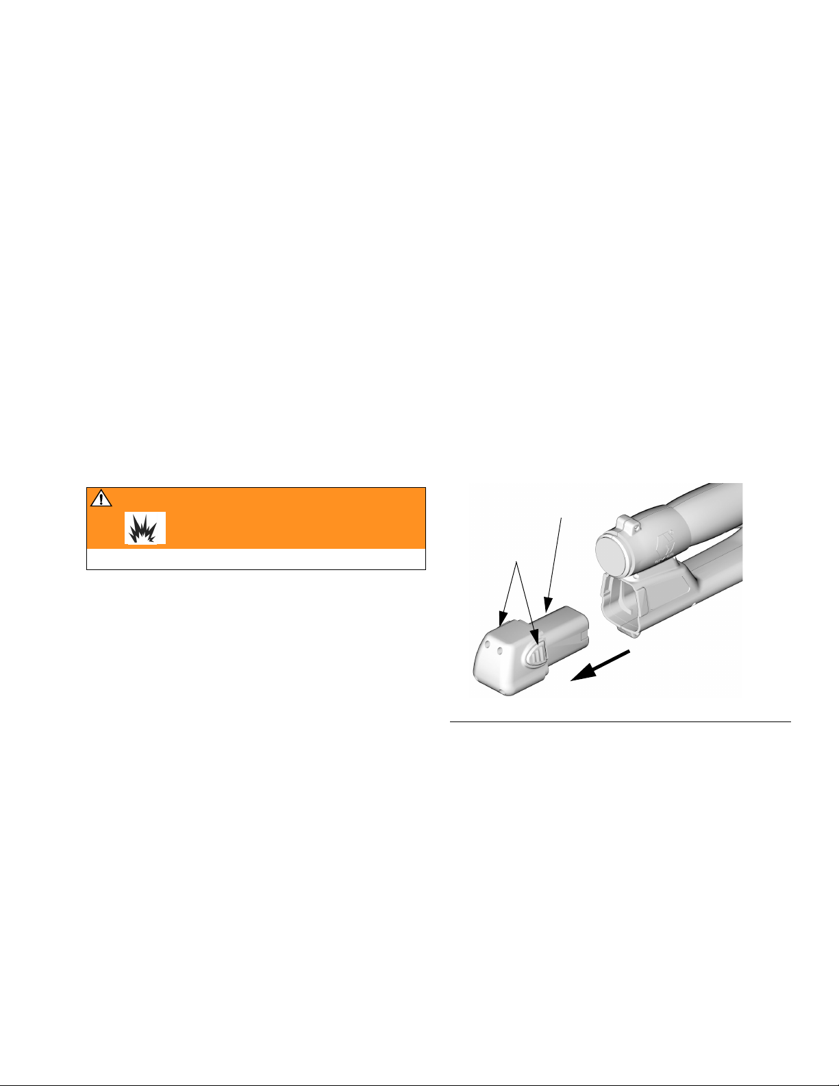
Removing and Replacing the Battery
.
WARNING
F
Read warnings on page 3.
1. Remove the battery by pressing in on both battery
lock buttons (E) and pulling the battery (F) out and
away from the Signal Tester. See F
2. Place the battery in the Graco Matrix battery charger. See Instruction Manual 309502 for details.
3. Replace the battery by pressing in on both battery
lock buttons (E) and pushing the battery (F) into the
Signal Tester.
IG. 1.
E
TI6746A
FIG. 1
4 311002C
Page 5

Display Functions
Display Functions
Asleep / Awake Mode
Asleep is a battery-saving mode in which the display
goes blank after a five-minute period of no button or trigger switch activity. An RF test lasting longer than five
minutes will stop and the LCD display backlight will go
out as the Signal Tester enters the sleep mode.
The display comes Awake from sleep mode when any
display button is pressed. RF testing will not automatically restart. To resume testing press the trigger switch.
Battery Life Indicator
On the right side of the display is a series of four bars
located under the word BATT. See F
of all four bars indicates a fully charged battery. The
bars decline in number as the Signal Tester is used and
the battery discharges. All Matrix signal tester batteries
should be re-charged using a Graco Matrix battery charger at the end of the working day to assure good performance the next day.
• Batteries can be recharged at anytime without
battery damage.
• At one bar on the display you will have about
20-40% of the charge remaining.
IG. 2. The presence
• If an RF Signal Tester is removed from service
for an extended time the battery should be
removed and recharged.
• If you see the message “Remove Low Battery Wait 30 Seconds Then Replace”, follow the
instructions and replace the low battery with a
fully charged battery. Do not do this proce-
dure during RF signal testing.
• Even when a Signal Tester is idle (asleep), the
Signal Tester is still functioning and the battery
will be used.
BATT
TRIGGER TO START
PROGRAM
Operation
Preliminary Settings
Power
1. To turn on the power to the RF Signal Tester insert a
fully charged battery. See F
Tester powers on to the main screen. See F
IG. 1. The RF Signal
IG. 3.
F
IG. 2
2. To turn off the power to the RF Signal Tester remove
the battery.
BATT
TRIGGER TO START
PROGRAM
FIG. 3
311002C 5
Page 6

Operation
Select Network and Transceiver ID
If necessary to determine the Transceiver dipswitch settings see Determining Transceiver Dipswitch Set-
tings on page 8 for a guide. It does not matter if an
RS232 connection or an RS422 connection is used
or will be used in the installation. To perform the test
all that’s needed is a powered on Transceiver and the
correct network ID and Transceiver ID entered into the
RF signal tester.
1. Press the left button (B) under PROGRAM to display the current Transceiver’s network and address
(NET WK ID A, TRANS ID A). See F
2. If necessary, enter a new letter for the network ID
and address ID for the target Transceiver. These
new settings are based on the target Transceiver dip
switch settings. (See manual 309498 for detailed dip
switch instructions).
Press the SELECT button (A) to toggle between the
Network and Transceiver ID. Use the center
up/down buttons (C) to change letter designations.
See F
IG. 4.
3. Press the PROGRAM button (B) to save settings
and return to the Main screen.
PROGRAM MODE
2.00.006
IG. 4.
If the PROGRAM screen is selected during an RF
signal test, the test will stop. The testing then must
be manually restarted.
Performing the RF Signal Test
1. Press the trigger switch to begin testing the signal
quality between the tester and the Transceiver. See
F
IG. 5.
TESTING . . .
MSGS SENT
10
PROGRAM
F
IG. 5
Once the RF test begins, the Signal Tester transmits ten
test messages to the Transceiver and “listens” for the
Transceiver to send a signal back to the Signal Tester
acknowledging that the message was received. This
series of ten test messages is called a test interval and
takes approximately ten seconds. However, the ten second interval can vary depending on the RF environment
and signal quality.
BATT
NET WK ID A
PROGRAM
B
F
IG. 4
The Network ID and Transceiver ID screen also
displays the software revision level for the tester.
See F
IG. 4.
6 311002C
TRANS ID A
SELECT
A
C
IMPORTANT: Do not move the Signal Tester while testing a specific location.
2. Once the series of ten signals is complete the Signal Tester screen will display the results as either a
GOOD SIGNAL or BAD SIGNAL. See F
GOOD SIGNAL
MSGS SENT
10
IG. 6.
BATT
PROGRAM
IG. 6
F
Page 7

Operation
GOOD SIGNAL: If over several test intervals the result
is consistently a GOOD SIGNAL, the location is within
the range of the Transceiver for reliable communication.
BAD SIGNAL: If the results are consistently a BAD SIGNAL, (despite an occasional GOOD SIGNAL reading),
the location is not within the range of reliable Transceiver communication.
3. Pressing the RF Tester trigger again resets the tester to zero and restarts the testing.
Pressing the trigger anytime during the test stops
the testing at the last message sent. Pressing the
RF tester trigger again resets the tester to zero and
restarts the testing.
LOCATING THE TRANSCEIVER(S)
Perform RF signal testing at all Meter and TLM locations
to determine an appropriate mounting location for the
Transceiver(s).
If a Transceiver needs to be repositioned or
another Transceiver needs to be added to the system, be sure to repeat RF signal testing at all Meter
and TLM locations in the facility to assure reliable
RF communication from the new Transceiver location(s).
Optional Display Information Explanation
Each test interval sends 10 messages to the Transceiver. Each of these 10 messages is resent up to 10
times or until the RF tester receives a response from the
Transceiver. If no response is received after resending
the individual message 10 times the RF tester moves on
to the next text message and resends it up to 10 times
or until a response is received from the Transceiver.
Once all 10 test interval messages have been sent and
RF testing is complete, the number of retries for each of
the 10 messages is totaled (anywhere from 1-100) and
then divided by 10 to get the AVG. RETRIES number.
This number is displayed on the RF tester screen.
For example, F
a total of 50 resend messages were bad out of a possible 100 (10 test interval messages x 10 retries = 100)
100
÷ 50 = 5.
A test interval that has an AVG. RETRIES of 4 or more
is considered a BAD SIGNAL. An average of less than 4
is considered a GOOD SIGNAL.
IG. 7 illustrates an RF interval test where
BAD SIGNAL
MSGS SENT
AVG. RETRIES
10
5
Optional Display Information
The number of retries for each test interval is used to
calculate if the return signal is a GOOD SIGNAL or a
BAD SIGNAL. This optional/additional information can
be displayed if desired for signal troubleshooting/analysis. It is not necessary to display this information for
general RF Signal testing.
On/Off
Optional information is displayed by pressing the up
center button (C) during the RF signal testing process.
Pressing the down center button (C) during the RF signal testing process hides this information. See F
311002C 7
IG. 7.
F
IG. 7
C
Page 8

Determining Transceiver Dipswitch Settings
Determining Transceiver Dipswitch Settings
Each Transceiver is equipped with two, 4 - position dipswitches labeled S1 and S2 representing the network ID
(S1) setting and the Transceiver ID (S2) setting. See
F
IG. 8. There is a possibility of (8) Network ID's and (8)
Transceiver ID's. The eight positions for each Network
ID and Transceiver ID are identified as A, B, C, D, E, F,
G, and H. See F
IG. 9 and FIG. 10.
• Network ID (S1): This is the RF identification
setting assigned to a Matrix installation. All components in the system use this same Network
ID. For example, if one dealership is using Network ID (A), the dealership across the street
would required Network ID (B) to avoid RF interference between the two systems.
• Transceiver ID (S2): This is the RF identifica-
tion setting assigned to a Matrix Transceiver(s).
Matrix system components are then assigned to
the Transceiver(s) ID's as desired for RF communication. For example, If a system required
two Transceivers, some components would be
assigned to one Transceiver and other components would be assigned to the second Transceiver using the Transceiver ID dipswitch.
Existing Matrix Facility - If the Transceiver is already
installed, two large letters should be visible on the outside of the box. The first letter represents the Network ID
and the second letter represents the Transceiver ID.
If no letters are present on the installed Transceiver, it
may be necessary to look inside the Transceiver box to
determine the dipswitch settings. First determine if an
RS232 or an RS422 connection is used and then refer
to F
IG. 9 and FIG. 10 to determine the Network ID and
Transceiver ID.
Testing can be completed while the Matrix system
is in use. The test messages sent by the RF Signal
Tester will be ignored by the PC that is connected
to the system.
New Matrix Facility - the factory default setting for all
Transceivers is (AA). The first A refers to the Network ID
and the second A refers to the Transceiver ID. It does
not matter in a new installation if an RS232 or an RS
422 connection will be used at the time of installation.
Transceiver ID (S2)
All dipswitches in down
or off position.
on
12
n
o
S1
All dipswitches
to right or off
position.
F
IG. 8
Transceiver Dipswitch Positions
S2
4
3
4
3
2
1
Network ID (S1)
8 311002C
Page 9

Dipswitch Settings using RA232 Connection.
S2 Transceiver ID
S2
C
on
12
3
A - default
on
12
3
B
on
S2
4
12
4
3
Determining Transceiver Dipswitch Settings
D
on
S2
4
12
3
S2
4
S2
G
on
12
3
E
on
12
F
on
S2
4
3
12
4
3
S1 Network ID
C
4
3
2
1
on
S1
D
4
3
2
1
n
o
S1
E
4
3
2
1
4
3
2
n
1
o
S1
FIG. 9
A - default
4
3
2
n
1
o
S1
B
on
S1
Dipswitch Setting using RS422 Connection
S2 Transceiver ID
S2
C
on
12
3
A
on
12
B
on
S2
4
3
12
4
3
H
on
S2
4
F
n
o
S1
4
3
2
1
12
G
4
3
2
n
1
o
S1
3
H
S2
4
4
3
2
n
1
o
S1
D
on
S2
4
12
3
S2
4
S2
G
on
12
H
on
S2
4
3
12
3
S2
4
E
on
12
F
on
S2
4
3
12
4
3
S1 Network ID
A
4
3
2
n
1
o
S1
F
IG. 10
311002C 9
B
on
S1
C
4
3
2
1
on
S1
D
4
3
2
1
n
o
S1
E
4
3
2
1
n
o
S1
F
4
3
2
1
on
S1
G
4
3
2
1
n
o
S1
H
4
3
2
1
4
3
2
n
1
o
S1
Page 10

Parts for 249269 and 249880 Matrix RF Signal Tester
Parts for 249269 and 249880 Matrix RF Signal Tester
1
TI6747
Battery is rechargeable and requires a Graco Matrix Battery Charger for recharging. See Instruction Manual 309502.
Ref.
No. Part No. Description Qty.
1 117310 BATTERY, 9.6V NMH rechargable 1
2 117427 CHARGER, single bay (not shown)
(N.A.) 1
120106 CHARGER, single bay (not shown)
(Australia) 1
3 117429 CHARGER, four bay (not shown)
(N.A.) 1
120107 CHARGER, four bay (not shown)
(Australia) 1
10 311002C
Page 11

Technical Specifications
Technical Specifications
Operating temperature range . . . . . . . . . . . . . . . . . . . . . . . . . . . . . . . . . . .32° F to 120° F (0° C to 49° C)
Storage temperature range. . . . . . . . . . . . . . . . . . . . . . . . . . . . . . . . . . -30° F to 120° F (-34° C to 49° C)
Battery . . . . . . . . . . . . . . . . . . . . . . . . . . . . . . . . . . . . . . . . . . rechargeable nickel-metal hydride 9.6 VDC
Battery storage temperature range. . . . . . . . . . . . . . . . . . . . . . . . . . . . . . .50° F to 86° F (10° C to 30° C)
RF Communication . . . . . . . . . . . . . . . . . . . . . 902-928 MHz frequency hopping, spread-spectrum (N.A.)
. . . . . . . . . . . . . . . . . . . . . . . . . . . . . . . . . 915-928 MHz frequency hopping, spread-spectrum (Australia)
Unobstructed RF Communication Range (based on building construction and RF environment) . . . . . . .
. . . . . . . . . . . . . . . . . . . . . . . . . . . . . . . . . . . . . . . . . . . . . . . . . . . . . . . . . . . . . .300-500 ft (91.0-152.0 m)
Obstructed RF Communication Range (based on building construction and RF environment) . . . . . . . . .
. . . . . . . . . . . . . . . . . . . . . . . . . . . . . . . . . . . . . . . . . . . . . . . . . . . . . . . . . . . . . . .250-300 ft (76.2-91.0 m)
Conformity (for 249880, Australia) . . . . . . . . . . . . . . . . . . . . . . . . . . . . . . . . . . . . . . . . . ACMA (Australia)
Approvals (for 249269 N.A.) . . . . . . . . . . . . . . . . . . . . . . . . . . . . . . . . . . . . . . .FCC, Industry Canada (IC)
Dimensions
A 12.0 in. (304.8 mm) overall length
B
4.75 in. (120.6 mm) overall width
C
5.25 in. (133.3 mm) overall height
B
C
A
TI6745
311002C 11
Page 12

Graco Standard Warranty
Graco warrants all equipment manufactured by Graco and bearing its name to be free from defects in material and workmanship
on the date of sale to the original purchaser for use. With the exception of any special, extended, or limited warranty published by
Graco, Graco will, for a period of twenty-four months from the date of sale, repair or replace any part of the equipment determined
by Graco to be defective. This warranty applies only when the equipment is installed, operated and maintained in accordance with
Graco's written recommendations.
This warranty does not cover, and Graco shall not be liable for general wear and tear, or any malfunction, damage or wear caused
by faulty installation, misapplication, abrasion, corrosion, inadequate or improper maintenance, negligence, accident, tampering,
or substitution of non-Graco component parts. Nor shall Graco be liable for malfunction, damage or wear caused by the
incompatibility of Graco equipment with structures, accessories, equipment or materials not supplied by Graco, or the improper
design, manufacture, installation, operation or maintenance of structures, accessories, equipment or materials not supplied by
Graco.
This warranty is conditioned upon the prepaid return of the equipment claimed to be defective to an authorized Graco distributor
for verification of the claimed defect. If the claimed defect is verified, Graco will repair or replace free of charge any defective parts.
The equipment will be returned to the original purchaser transportation prepaid. If inspection of the equipment does not disclose
any defect in material or workmanship, repairs will be made at a reasonable charge, which charges may include the costs of parts,
labor, and transportation.
THIS WARRANTY IS EXCLUSIVE, AND IS IN LIEU OF ANY OTHER WARRANTIES, EXPRESS OR IMPLIED, INCLUDING BUT
NOT LIMITED TO WARRANTY OF MERCHANTABILITY OR WARRANTY OF FITNESS FOR A PARTICULAR PURPOSE.
Graco's sole obligation and buyer's sole remedy for any breach of warranty shall be as set forth above. The buyer agrees that no
other remedy (including, but not limited to, incidental or consequential damages for lost profits, lost sales, injury to person or
property, or any other incidental or consequential loss) shall be available. Any action for breach of warranty must be brought within
two (2) years of the date of sale Graco makes no warranty, and disclaims all implied warranties of merchantability and fitness for a
particular purpose in connection with accessories, equipment, materials or components sold but not manufactured by Graco.
These items sold, but not manufactured by Graco (such as electric motors, switches, hose, etc.), are subject to the warranty, if any,
of their manufacturer. Graco will provide purchaser with reasonable assistance in making any claim for breach of these warranties.
In no event will Graco be liable for indirect, incidental, special or consequential damages resulting from Graco supplying
equipment hereunder, or the furnishing, performance, or use of any products or other goods sold hereto, whether due to a breach
of contract, breach of warranty, the negligence of Graco, or otherwise.
FOR GRACO CANADA CUSTOMERS
The parties acknowledge that they have required that the present document, as well as all documents, notices and legal
proceedings entered into, given or instituted pursuant hereto or relating directly or indirectly hereto, be drawn up in English. Les
parties reconnaissent avoir convenu que la rédaction du présente document sera en Anglais, ainsi que tous documents, avis et
procédures judiciaires exécutés, donnés ou intentés à la suite de ou en rapport, directement ou indirectement, avec les
procedures concernées.
Graco Phone Numbers
TO PLACE AN ORDER, contact your Graco distributor or call to identify the nearest distributor.
Phone: 612-623-6928 or Toll Free: 1-800-533-9655, Fax: 612-378-3590
All written and visual data contained in this document reflects the latest product information available at the time of publication.
GRACO INC. AND SUBSIDIARIES • P.O. BOX 1441 • MINNEAPOLIS MN 55440-1441 • USA
Copyright 2004, Graco Inc. All Graco manufacturing locations are registered to ISO 9001.
Graco reserves the right to make changes at any time without notice.
For patent information, see www.graco.com/patents.
Original instructions. This manual contains English. MM 311002
Graco Headquarters: Minneapolis
International Offices: Belgium, China, Japan, Korea
www.graco.com
Revised July 2012
 Loading...