

Page 1
Repair - Parts
309813H
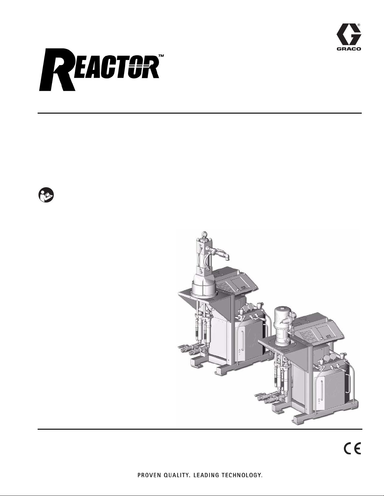
Air Powered, Heated, Plural Component
Proportioners
For spraying polyurethane foam and polyurea coatings.
Not for use in explosive atmospheres.
Important Safety Instructions
Read all warnings and instructions in this manual.
Save these instructions.
For model information, see page 3.
TI3699b
Page 2
Manual Conventions
Contents
Manual Conventions . . . . . . . . . . . . . . . . . . . . . . . . 2
Models . . . . . . . . . . . . . . . . . . . . . . . . . . . . . . . . . . . 3
Air Powered Reactors . . . . . . . . . . . . . . . . . . . . . 3
Supplied Manuals . . . . . . . . . . . . . . . . . . . . . . . . . . 4
Related Manuals . . . . . . . . . . . . . . . . . . . . . . . . . . . 5
Warning . . . . . . . . . . . . . . . . . . . . . . . . . . . . . . . . . . . 6
Before Beginning Repair . . . . . . . . . . . . . . . . . . . . 8
Flushing . . . . . . . . . . . . . . . . . . . . . . . . . . . . . . . . . . 8
Pressure Relief Procedure . . . . . . . . . . . . . . . . . . . 9
Temperature Control Diagnostic Codes . . . . . . . 10
E01: High fluid temperature . . . . . . . . . . . . . . . 10
E02: High hose current . . . . . . . . . . . . . . . . . . . 10
E03: No hose current . . . . . . . . . . . . . . . . . . . . 11
E04: FTS or thermocouple not connected . . . . 11
E05: Board overtemperature . . . . . . . . . . . . . . . 11
Manual Conventions
Troubleshooting . . . . . . . . . . . . . . . . . . . . . . . . . . . 12
Repair . . . . . . . . . . . . . . . . . . . . . . . . . . . . . . . . . . . 15
Proportioning Pump . . . . . . . . . . . . . . . . . . . . . . 15
Circuit Breaker Module . . . . . . . . . . . . . . . . . . . 16
Temperature Control Board . . . . . . . . . . . . . . . . 18
Heater . . . . . . . . . . . . . . . . . . . . . . . . . . . . . . . . 20
Heated Hose . . . . . . . . . . . . . . . . . . . . . . . . . . . 22
Fluid Temperature Sensor (FTS) . . . . . . . . . . . . 23
Display Module . . . . . . . . . . . . . . . . . . . . . . . . . 29
Parts . . . . . . . . . . . . . . . . . . . . . . . . . . . . . . . . . . . . 32
Technical Data . . . . . . . . . . . . . . . . . . . . . . . . . . . . 49
Graco Standard Warranty . . . . . . . . . . . . . . . . . . . 50
Graco Information . . . . . . . . . . . . . . . . . . . . . . . . . 50
Warning
WARNING
A warning alerts you to possible serious injury or
death if you do not follow instructions.
Symbols, such as fluid injection (shown), alert you to a
specific hazard and direct you to read the indicated
hazard warnings on pages 6-7.
Caution
CAUTION
A caution alerts you to possible equipment damage or
destruction if you do not follow instructions.
Note
A note indicates additional helpful information.
2 309813H
Page 3
Models
Air Powered Reactors
A-XP SERIES
Models
Full
Load
Part No.,
Series Model
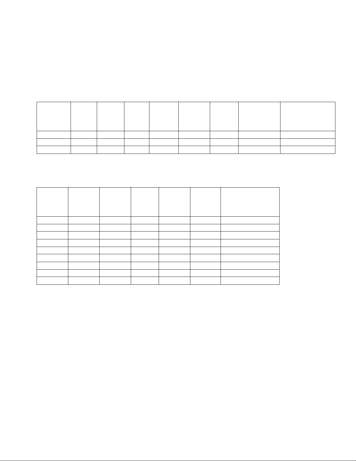
246639, B A-XP2 230V (1) 62 14,540 10,200 1 (3.8) .0193 (.073) 3000 (20.7, 207)
246752, B A-XP2 230V (3) 40 14,540 10,200 1 (3.8) .0193 (.073) 3000 (20.7, 207)
246753, B A-XP2 380V (3) 22 14,540 10,200 1 (3.8) .0193 (.073) 3000 (20.7, 207)
Voltag e
(phase)
Peak
Amps*
System
Watts**
Heater
Watts
(no hose)
Flow
gpm
(lpm) at
78 cpm
Output per
Cycle (A + B)
gal. (liter)
Maximum Fluid
Working Pressure
psi (MPa, bar)
Heat Packages (do not include proportioner)
Full
Load
Part No.,
Series Model
246365, B HT-6.0 230V (1) 44 10,340 6,000 3500 (24.1, 241)
246760, B HT-6.0 230V (3) 27 10,340 6,000 3500 (24.1, 241)
246761, B HT-6.0 380V (3) 18 10,340 6,000 3500 (24.1, 241)
246607, B HT-10.2 230V (1) 62 14,540 10,200 3500 (24.1, 241)
246762, B HT-10.2 230V (3) 40 14,540 10,200 3500 (24.1, 241)
246763, B HT-10.2 380V (3) 22 14,540 10,200 3500 (24.1, 241)
246364, B HT-15.3 230V (1) 84 19,640 15,300 3500 (24.1, 241)
246764, B HT-15.3 230V (3) 57 19,640 15,300 3500 (24.1, 241)
246765, B HT-15.3 380V (3) 33 19,640 15,300 3500 (24.1, 241)
Voltag e
(phase)
Peak
Amps*
System
Watts**
Heater
Watts
(no hose)
Maximum Fluid
Working Pressures
psi (MPa, bar)
* Full load amps with all devices operating at maximum capabilities. Fuse requirements at various flow rates and mix chamber
sizes may be less.
**Total system watts for all units, using 310 ft (94.6 m) hose.
309813H 3
Page 4
Supplied Manuals
Supplied Manuals
The following manuals are shipped with the Reactor™.
Refer to them for detailed equipment information.
Air and Hydraulic Reactors
Part No. Description
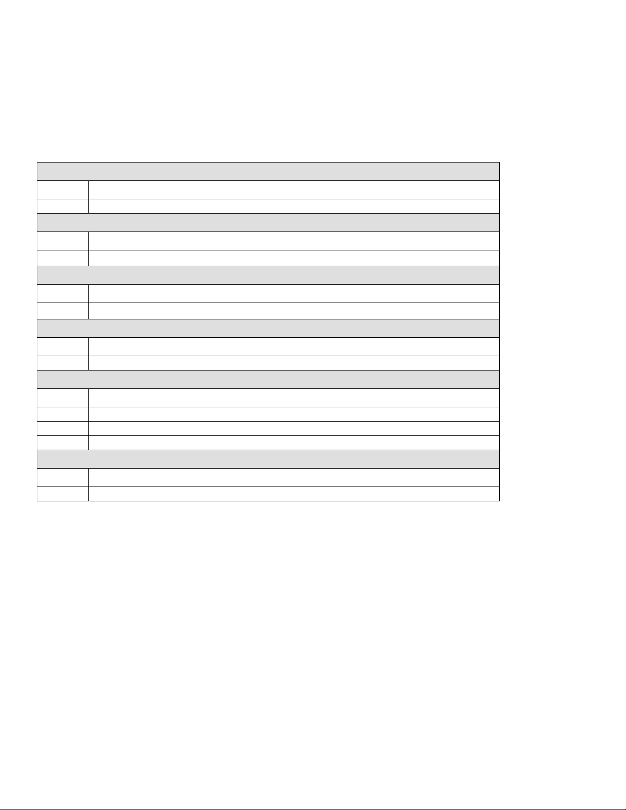
309812 Air and Hydraulic Reactors, Operation Manual (English)
Proportioning Pumps
Part No. Description
308224
Motors
Part No. Description
306982
Displacement Pumps
Part No. Description
307430 Displacement Pumps Repair-Parts Manual (English)
Reactor Electrical Diagrams (one of following included)
Part No. Description
309854 Electrical Diagrams, 230V 1 phase
309855 Electrical Diagrams, 230V 3 phase
309576 Electrical Diagrams, 380V 3 phase
Air Regulators (air powered units only)
President
President
®
Pump Repair-Parts Manual (English)
®
Air Motor Repair-Parts Manual (English)
Order Part No. 15B535 for a compact disk of Reactor
manuals translated in several languages.
Part No. Description
308168 Instruction-Parts Manual (English)
4 309813H
Page 5
Related Manuals
Related Manuals
The following manuals are for accessories used with the
Reactor
™
.
Hydraulic Power Supply
Part No. Description
307550 Instruction-Parts Manual (English)
Feed Pump Kits
Part No. Description
309815 Instruction-Parts Manual (English)
Air Supply Kit
Part No. Description
309827 Instruction-Parts Manual (English) for Feed Pump Air Supply Kit
Circulation and Return Tube Kits
Part No. Description
309852 Instruction-Parts Manual (English)
Heated Hose
Order Part No. 15B535 for a compact disk of Reactor
manuals translated in several languages.
Order Part No. 15B381 for a compact disk of Fusion
manual translated in several languages.
Part No. Description
309572 Instruction-Parts Manual (English)
Fusion Air Purge Spray Gun
Part No. Description
309550 Instruction-Parts Manual (English)
Fusion Mechanical Purge Spray Gun
Part No. Description
309856 Instruction-Parts Manual (English)
Circulation Kit
Part No. Description
309818 Instruction-Parts Manual (English)
Data Reporting Kit
Part No. Description
309814 Instruction-Parts Manual (English)
309813H 5
Page 6
Warning
WARNING
SKIN INJECTION HAZARD
High-pressure fluid from gun, hose leaks, or ruptured components will pierce skin. This may look like just
a cut, but it is a serious injury that can result in amputation. Get immediate surgical treatment.
• Do not point the gun at anyone or at any part of the body.
• Do not put your hand or fingers over the gun fluid nozzle.
• Do not stop or deflect leaks with your hand, body, glove, or rag.
• Do not “blow back” fluid; this is not an air spray system.
• Follow Pressure Relief Procedure, page 9, when you stop spraying and before cleaning, checking,
or servicing equipment.
• Use lowest possible pressure when flushing, priming, or troubleshooting.
• Engage spray gun piston safety lock when not spraying.
• Tighten all fluid connections before operating the equipment.
• Check hoses, tubes, and couplings daily. Replace worn or damaged parts immediately. High pressure hose cannot be recoupled; replace the entire hose.
FIRE, EXPLOSION, AND ELECTRIC SHOCK HAZARD
Solvent and fumes in work area can ignite or explode. High voltage components can cause electric
shock. To help prevent fire, explosion, and electric shock:
• Shut off main power switch and wait 5 minutes before opening Reactor cabinet door.
• All electrical wiring must be done by trained and qualified personnel and comply with all local codes.
• Ground equipment and conductive objects. See Grounding in the Operation manual.
• Use equipment only in well ventilated area.
• Eliminate all ignition sources, such as pilot lights, cigarettes and plastic drop cloths (potential static
arc).
• Do not plug or unplug power cords or turn lights on or off when flammable fumes are present.
• Keep the work area free of debris, including solvent, rags, and gasoline.
• Hold gun firmly to side of grounded pail when triggering into pail.
• Use only grounded hoses.
• If there is static sparking or you feel a shock, stop operation immediately. Do not use equipment
until you identify and correct the problem.
• To avoid chemical reaction and explosion, do not use 1,1,1-trichloroethane, methylene chloride,
other halogenated hydrocarbon solvents or fluids containing such solvents in pressurized aluminum
equipment.
6 309813H
Page 7
Warning
WARNING
EQUIPMENT MISUSE HAZARD
Misuse can cause serious injury or death.
• For professional use only.
• Use equipment only for its intended purpose. Call your Graco distributor for information.
• Read manuals, warnings, tags, and labels before operating equipment. Follow instructions.
• Check equipment daily. Repair or replace worn or damaged parts immediately.
• Do not alter or modify equipment. Use only Graco parts and accessories.
• Do not exceed the maximum working pressure or temperature rating of the lowest rated system
component. See Technical Data in all equipment manuals.
• Use fluids and solvents that are compatible with equipment wetted parts. See Technical Data in all
equipment manuals. Read fluid and solvent manufacturer’s warnings.
• Route hoses and cables away from traffic areas, sharp edges, moving parts, and hot surfaces.
• Do not use hoses to pull equipment.
• Comply with all applicable safety regulations.
BURN HAZARD
This equipment is used with heated fluid, which can cause equipment surfaces to become very hot. To
avoid severe burns:
• Do not touch hot fluid or equipment.
• Allow equipment to cool completely before touching it.
• Wear gloves if fluid temperature exceeds 110°F (43°C).
TOXIC FLUID OR FUMES HAZARD
Toxic fluids or fumes can cause serious injury or death if splashed in the eyes or on skin, inhaled, or
swallowed.
• Read Material Safety Data Sheet (MSDS) to know the specific hazards of the fluids you are using.
• Store hazardous fluid in approved containers, and dispose of it according to applicable guidelines.
PERSONAL PROTECTIVE EQUIPMENT
You must wear proper protective equipment when operating, servicing, or when in the operating area of
the equipment to help protect you from serious injury, including eye injury; inhalation of toxic fumes; and
hearing loss. This equipment includes but is not limited to:
• Protective eyewear.
• Gloves, clothing, and respirator as recommended by the fluid and solvent manufacturer.
• Hearing protection.
309813H 7
Page 8
Before Beginning Repair
Before Beginning
Repair
WARNING
Repairing this equipment requires access to parts
which may cause electric shock or other serious injury
if work is not performed properly. Have a qualified
electrician connect power and ground to main power
switch terminals, see the Operation manual. Be sure
to shut off all power to the equipment before repairing.
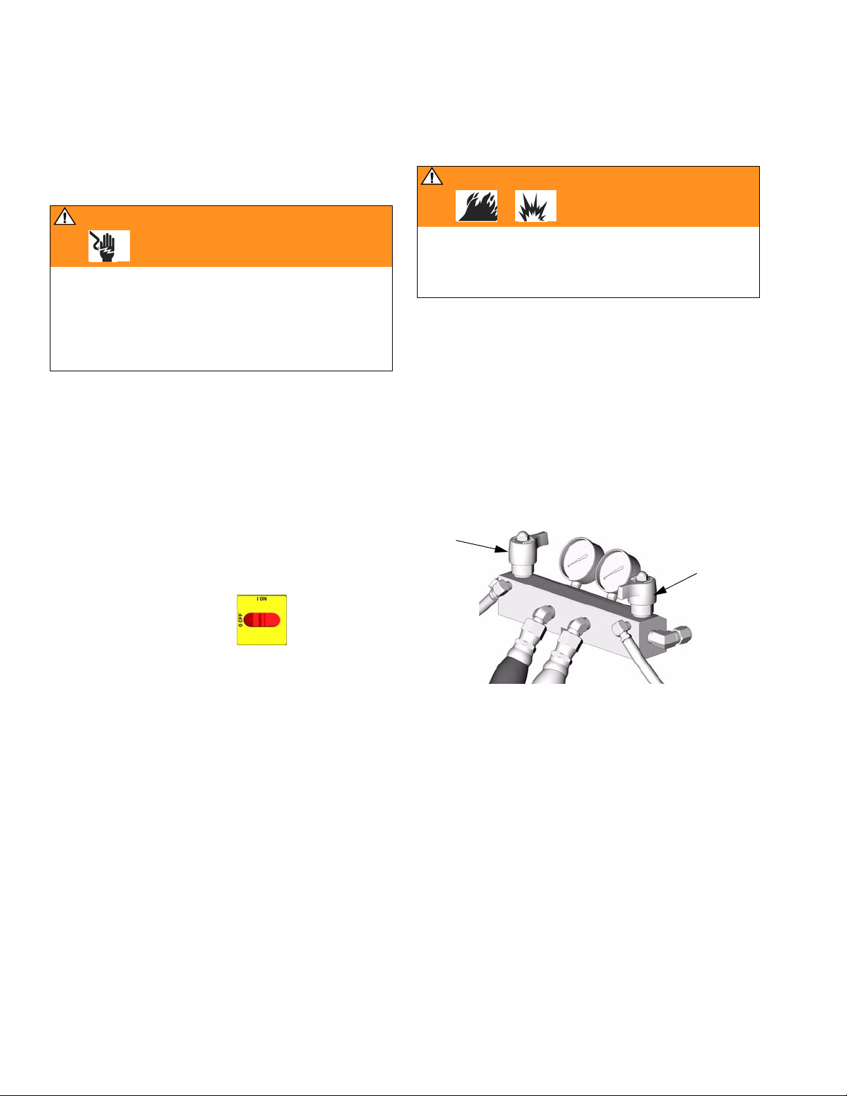
1. Flush if necessary, see right.
2. Trigger gun to park pumps at bottom of stroke.
Flushing
WARNING
Read warnings, page 6. Flush equipment only in a
well-ventilated area. Do not spray flammable fluids. Do
not turn on heaters while flushing with flammable solvents.
• Flush out old fluid with new fluid, or flush out old
fluid with a compatible solvent before introducing
new fluid.
• Use the lowest possible pressure when flushing.
• All fluid components are compatible with common
solvents. Use only moisture-free solvents.
• To flush feed hoses, pumps, and heaters separately
from heated hoses, set PRESSURE
RELIEF/SPRAY valves (SA, SB) to PRESSURE
RELIEF.
3. Fill wet-cups. See operation manual.
4. Turn main power OFF .
5. Close red-handled valve to shut off power to
motor.
6. Relieve pressure, page 9.
SA
SB
TI3593a
• To flush entire system, circulate through gun fluid
manifold (with manifold removed from gun).
• Always leave some type of fluid in system. Do not
use water.
8 309813H
Page 9
Pressure Relief Procedure
Pressure Relief
Procedure
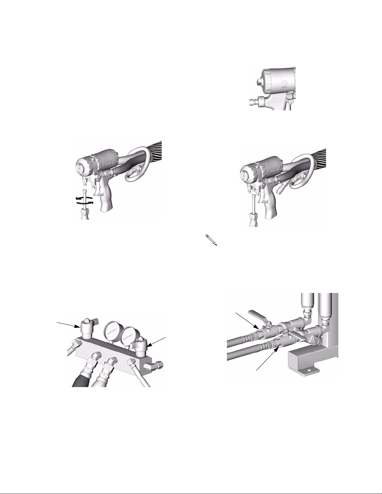
1. Relieve pressure in gun and perform gun shutdown
procedure. See gun manual.
2. Verify gun fluid manifold valves A and B are closed.
TI2421A
6. Engage gun piston safety lock.
TI2409A
7. Disconnect gun air line and remove gun fluid manifold.
TI2543A
3. Shut off feed pumps and agitator, if used.
4. Check that red-handled valve is closed, to shut off
power to motor.
5. Turn PRESSURE RELIEF/SPRAY valves (SA, SB)
to PRESSURE RELIEF. Route fluid to waste containers or supply tanks. Ensure gauges drop to 0.
SA
SB
TI3593a
Pump throat seals work best under pressure.
Close fluid inlet valves (VA, VB) when Reactor is
depressurized, to prevent drum head pressure
from leaking past pump piston seals.
8. Close fluid inlet valves (VA, VB).
VA
VB
TI3698b
309813H 9
Page 10
Temperature Control Diagnostic Codes
Temperature Control Diagnostic Codes
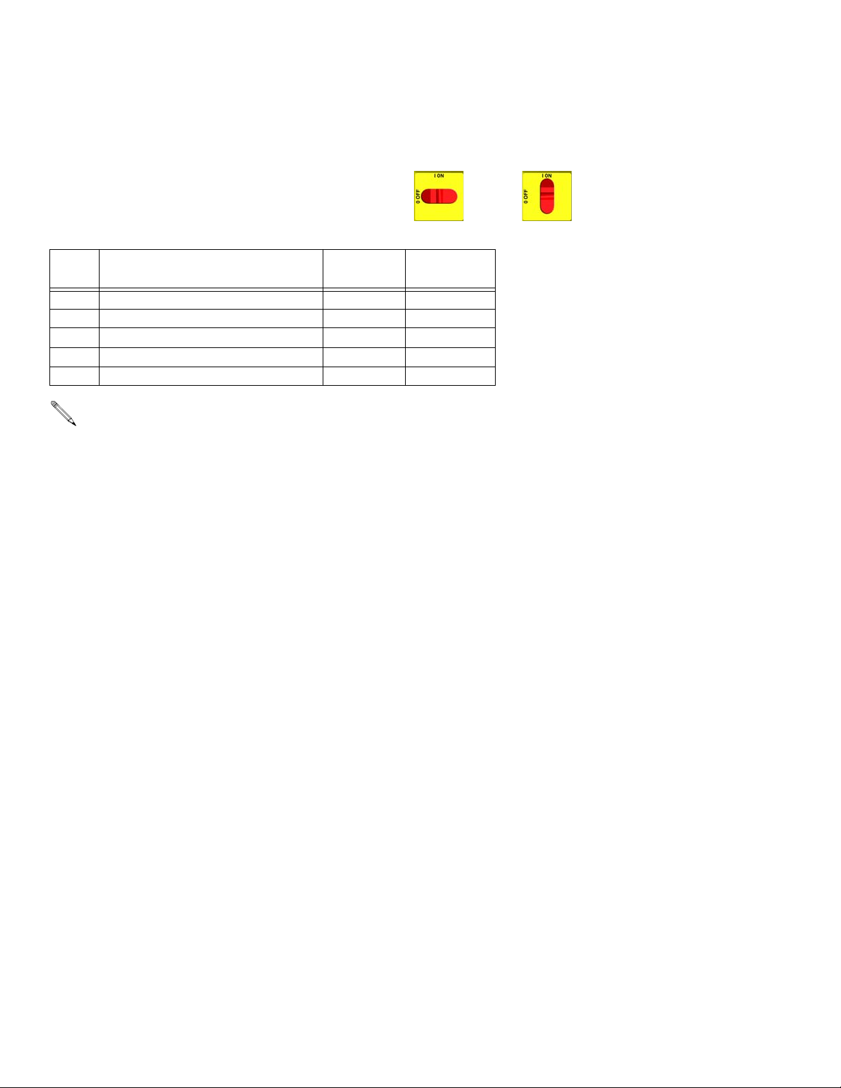
Temperature control diagnostic codes E01 through E05
appear on temperature display.
Code
No.
01 High fluid temperature Individual 10
02 High hose current Hose only 10
03 No hose current with hose heater on Hose only 11
04 FTS or thermocouple not connected Individual 11
05 Board overtemperature All 11
For hose zone only, if FTS is disconnected at startup, display will show hose current 0A.
Code Name Alarm Zone Corrective
These alarms turn off heat. Turn main power OFF
then ON to clear.
Action page
E01: High fluid temperature E02: High hose current
a. Check connections between temperature control
board and heater overtemperature switches,
page 22.
a. Check tap connection at transformer, see opera-
tion manual.
b. Check temperature sensors, page 21.
c. Check temperature sensor is contacting heater
element, page 21.
b. Check hose connections for electrical short,
page 22.
c. Move to lower hose length on transformer.
d. Replace temperature control board, page 18.
10 309813H
Page 11

Temperature Control Diagnostic Codes
E03: No hose current
Do steps in order. Do not skip any step.
a. Check hose connectors for broken electrical
connection, page 22.
b. Test hose continuity, page 25.
c. Test transformer wire harness continuity, page
25.
d. Check 50A (806) and 20A (817A) circuit break-
ers, page 16.
e. Test current sensor continuity, page 25.
f. Do In-Rush Current Limiter Check (380V
only), page 27
e. Use manual current control mode; see operation
manual.
E05: Board overtemperature
a. Check fan operation.
b. Check electrical cabinet door is properly
installed.
c. Check for obstructions blocking cooling holes in
bottom of Reactor.
d. Ambient temperature too high. Reduce gun mix
chamber size, or move Reactor to a cooler location.
g. Do Transformer Primary Check, page 27.
h. Do Transformer Secondary Check, page 27.
E04: FTS or thermocouple
not connected
a. Check FTS operation by connecting directly to
Reactor.
b. Check cable connections between all hose
lengths.
c. Check temperature sensor connection at J1 on
temperature control board, page 18.
d. Check thermocouple with ohmmeter, page 23.
309813H 11
Page 12
Troubleshooting
Troubleshooting
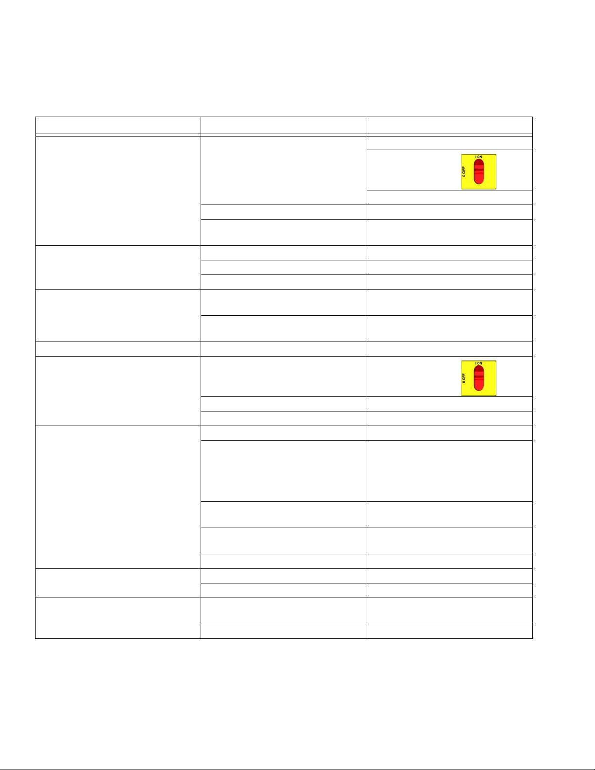
PROBLEM CAUSE SOLUTION
Reactor does not operate. No power. Plug in power cord.
Tur n m ain pow er O N .
Turn circuit breakers ON, page 16.
No air or hydraulic power. Open red-handled valve.
Red stop button circuit open. Check button connections. See page
29 and electrical diagrams.
Fan not working. Blown fuse. Replace, page 17.
Loose wire. Check.
Defective fan. Replace, page 17.
Pump output low. Obstructed fluid hose or gun; fluid
hose ID too small.
Worn piston valve or intake valve in
displacement pump.
Fluid leak in pump packing nut area. Worn throat seals. Replace. See pump manual.
No display. Main power OFF. Turn main power ON .
Open, clear; use hose with larger ID.
See pump manual.
Loose display cable. Check cable connections, page 29.
Display board failed. Check board, replace; page 29.
No temperature display. Loose display cable. Check cable connections, page 29.
Failed temperature control board. Open cabinet. Check if board LED is
blinking. If not, check power wiring
connections to ensure board has
power. If board has power and LED is
not blinking, replace board, page 18.
Inadequate power to temperature
board.
Loose power cable (internal to dis-
play).
Defective display board. Replace, page 29.
No cycle counter display. Loose display cable. Check cable connections, page 29.
Defective counter. Replace, page 29.
Does not count. Magnet (26) missing from pump
yoke.
Defective reed switch (27). Replace.
Check that power supply meets
requirements.
Check cable connections, page 29.
Replace.
12 309813H
Page 13
PROBLEM CAUSE SOLUTION
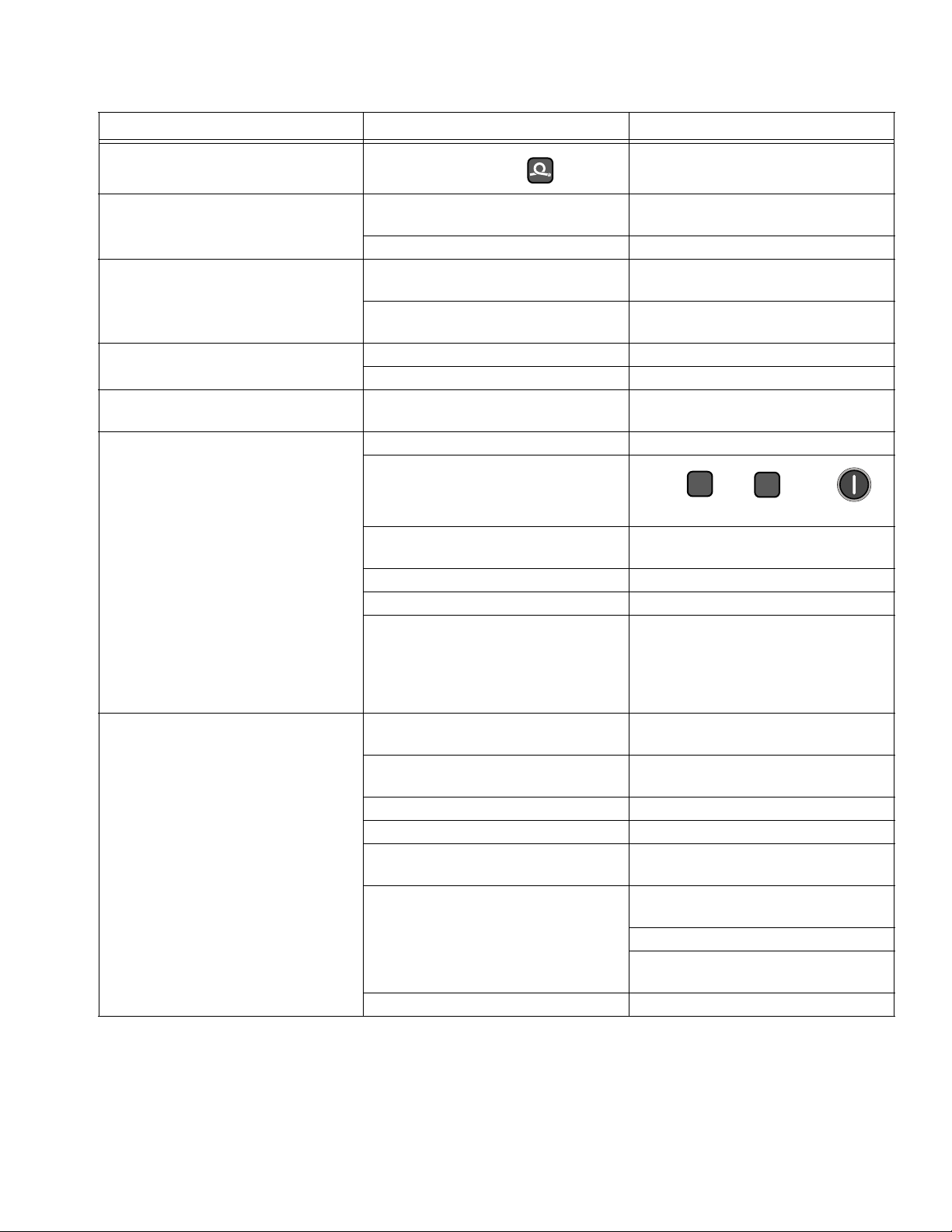
Hose display reads 0A on startup.
FTS not installed and zone off.
Troubleshooting
Install FTS (see operation manual),
or adjust current to desired setting.
Erratic display; display turns on and
off.
Display buttons do not work properly;
cannot get out of an operation.
Red stop button does not work. Broken button (fused contact). Replace, page 29.
No heat in any zone. Red stop button circuit open. Check button connections. See page
No heat in A or B zones. Circuit breaker(s) tripped. Reset breaker CB3 or CB4, page 16.
Low heat in A or B zones. A and B temperature setpoints too
Cable not grounded. Ground cable, page 29.
Extension cable too long. Must not exceed 100 ft (30.5 m).
Broken membrane switch. Replace, page 29.
Ribbon cable disconnected or broken.
Loose wire. Check connections, page 29.
Heat turned off.
Temperature control alarm. Check temperature displays for diag-
Defective heater. Replace, page 20. Check resistance.
Loose connectors or wire nuts. Check connections.
Failed temperature control board. Open cabinet. Check if board LED is
low.
Flow too high. Use smaller mix chamber. Decrease
Defective heater. Replace, page 20. Check resistance.
Loose connectors or wire nuts. Check connections.
Low voltage. Check that power supply meets
Overheated temperature control
board.
Fluid too cold. Preheat fluid.
Connect cable, or replace.
29 and electrical diagrams.
Press or zone
keys.
nostic code, page 10.
blinking. If not, check power wiring
connections to ensure board has
power. If board has power and LED is
not blinking, replace board, page 18.
Check setpoint. Increase if necessary.
pressure.
requirements.
Check fan operation.
Check if door is open; close.
Check that cooling holes are not
clogged or obstructed.
A
B
309813H 13
Page 14
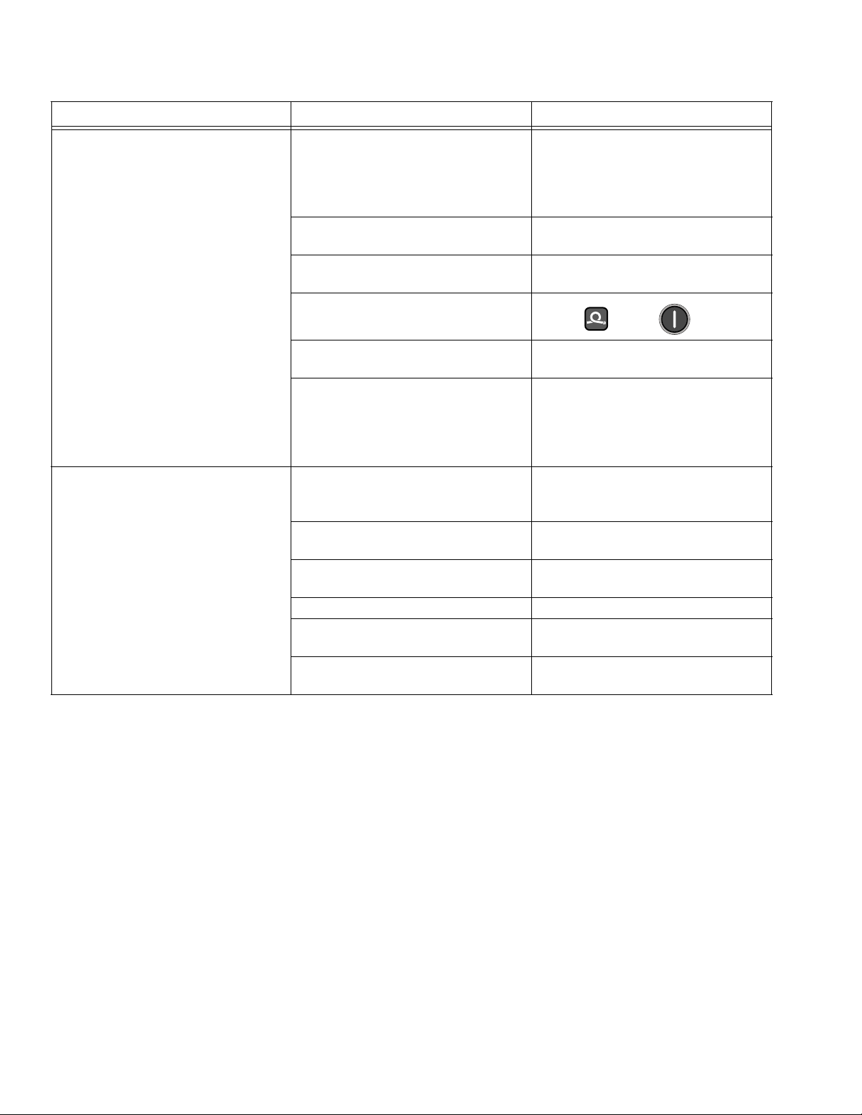
Troubleshooting
PROBLEM CAUSE SOLUTION
No hose heat. 380V units only - In-rush current lim-
iter contactor not closing when hose
heat is turned on.
Loose hose electrical connections. Check connections. Repair as neces-
Circuit breakers tripped. Reset breakers (CB1 or CB2), page
Hose zone not turned on.
Check to be sure contactor in 288359
is closing when hose heat is turned
on. If not, check fuse (198). If fuse is
not blown, perform transformer
checks.
sary.
16.
Press zone key.
A and B temperature setpoints too
low.
Failed temperature control board. Open cabinet. Check if board LED is
Low hose heat. A and B temperature setpoints too
low.
Hose temperature setpoint too low. Check. Increase if necessary to
Flow too high. Use smaller mix chamber. Decrease
Low current; FTS not installed. Install FTS, see operation manual.
Hose heat zone not turned on long
enough.
Loose hose electrical connections. Check connections. Repair as neces-
Check. Increase if necessary.
blinking. If not, check power wiring
connections to ensure board has
power. If board has power and LED is
not blinking, replace board, page 18.
Increase A and B setpoints. Hose
designed to maintain temperature,
not increase temperature.
maintain heat.
pressure.
Allow hose to heat up, or preheat
fluid.
sary.
14 309813H
Page 15
Repair
Proportioning Pump
Removal
Repair
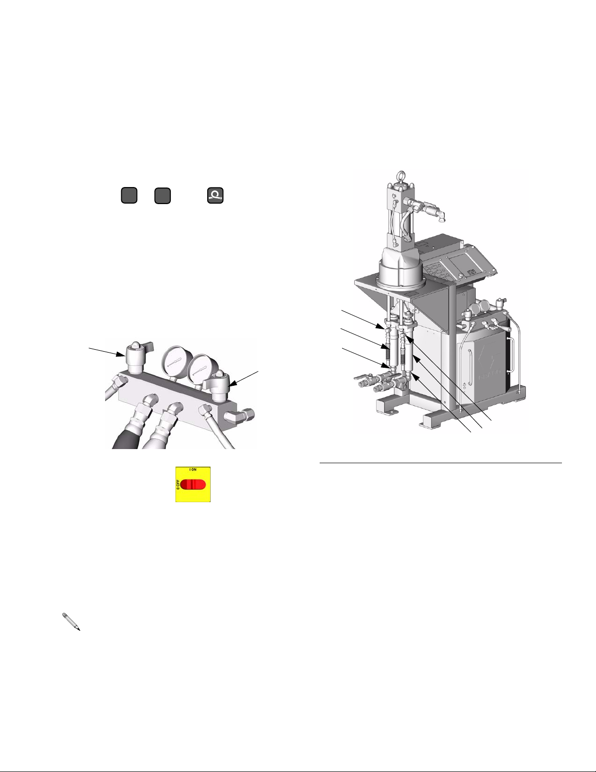
1. Shut off , , and heat zones.
2. Flush pump, page 8.
3. Relieve pressure, page 9.
4. Turn PRESSURE RELIEF/SPRAY valves (SA, SB)
to PRESSURE RELIEF.
SA
A
B
SB
TI3593a
D
E
C
FIG. 1. Pump Removal
D
E
C
TI3582b
5. Turn main power OFF . Disconnect power
supply.
6. Disconnect hoses and fittings from fluid inlets (C)
and outlets (D). See F
7. Remove pump. See applicable manuals, supplied.
See page 4 for applicable pump and motor
repair-parts manuals. Displacement pumps (E)
may be removed without removing entire proportioning pump.
8. Reinstall in reverse order.
309813H 15
IG. 1.
Page 16
Repair
Circuit Breaker Module
1. Turn main power OFF . Disconnect power
supply.
WARNING
Read warnings, page 6.
2. Relieve pressure, page 9.
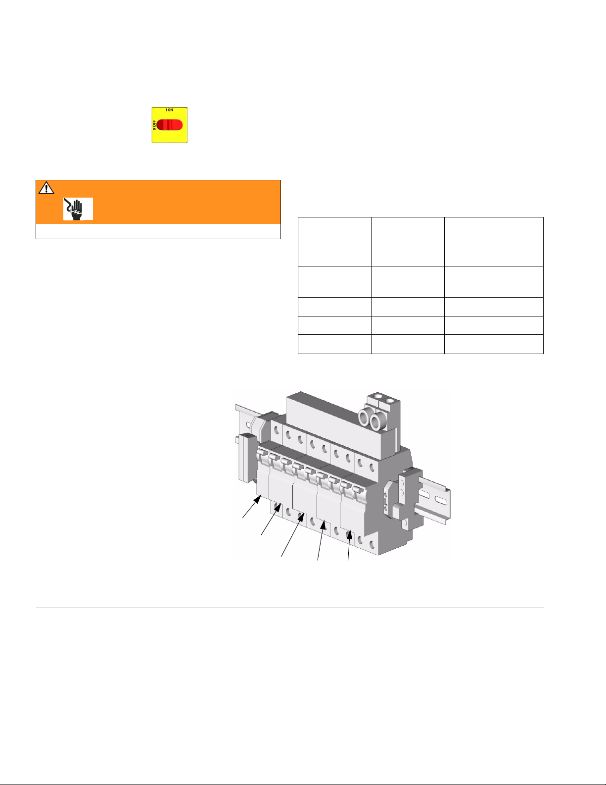
3. Using an ohmmeter, check for continuity across circuit breaker (top to bottom). If no continuity, trip
breaker, reset, and retest. If still no continuity,
replace breaker as follows:
a. Refer to electrical diagrams and to T
connect wires and remove bad breaker.
b. Install new breaker and reconnect wires.
Table 1: Circuit Breakers, see FIG. 2
Ref. No. Size Component
806 50 A Hose/Transformer
Secondary Side
817A 20 A Transformer
804A 25 or 40 A* Heater A
804B 25 or 40 A* Heater B
817B 20 A Not Used
* Depending on model.
ABLE 1. Dis-
Primary
806
NOTE: To reference cables and connectors, see the electrical diagrams and
the parts drawings on pages 45-47.
FIG. 2. Circuit Breaker Module
16 309813H
817A
804A 817B
804B
TI2514A
Page 17
Fan
Repair
2. Relieve pressure, page 9.
1. Turn main power OFF . Disconnect power
supply.
WARNING
Read warnings, page 6.
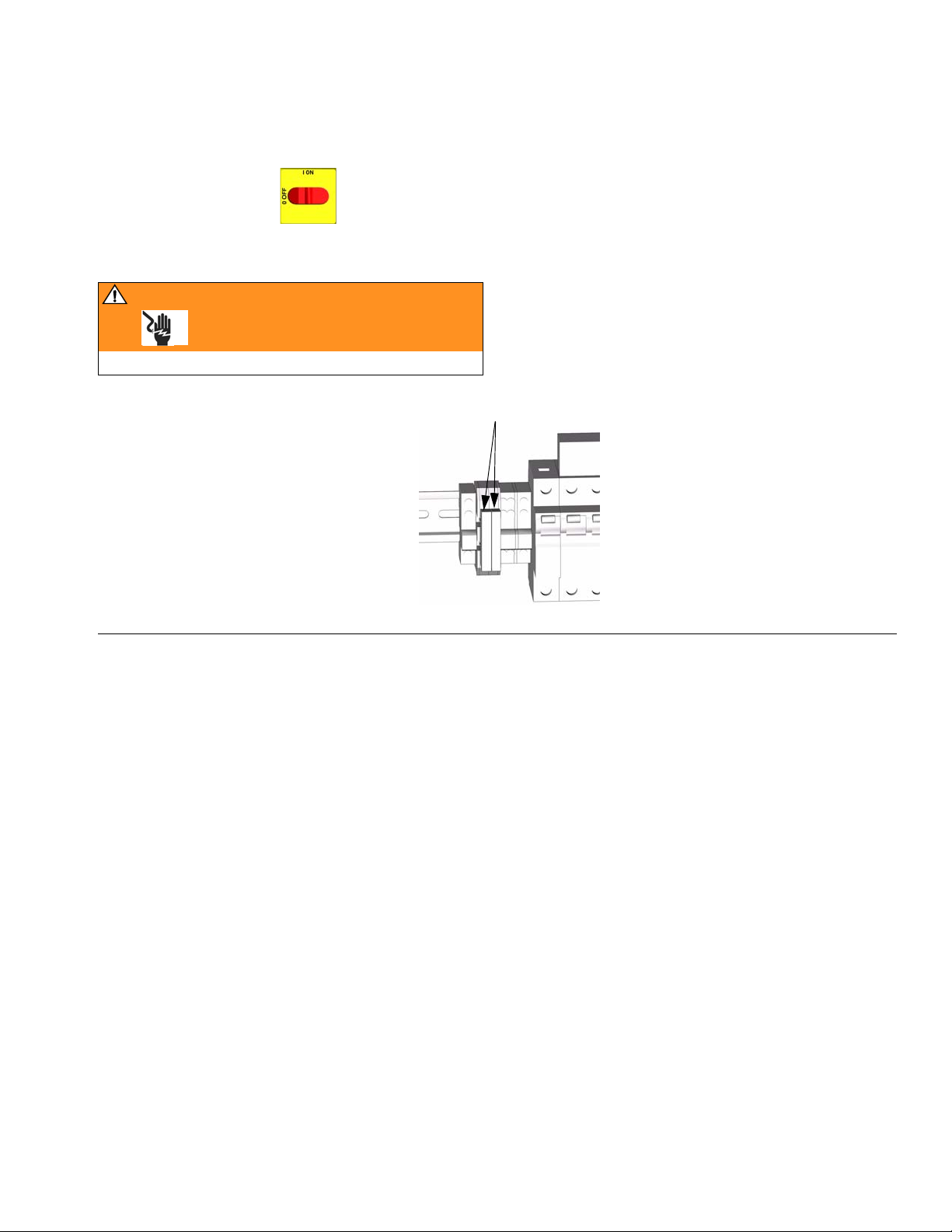
FIG. 3. Fan Fuses
3. Check fuses (F) at left of breaker module, F
Replace if blown. If good, continue with step 4.
4. Refer to electrical diagrams. Disconnect fan wires
from fuses (F). Thread wires through top of cabinet.
5. Remove fan.
6. Install fan in reverse order.
F
TI2514A-1
IG. 3.
309813H 17
Page 18
Repair
Temperature Control Board
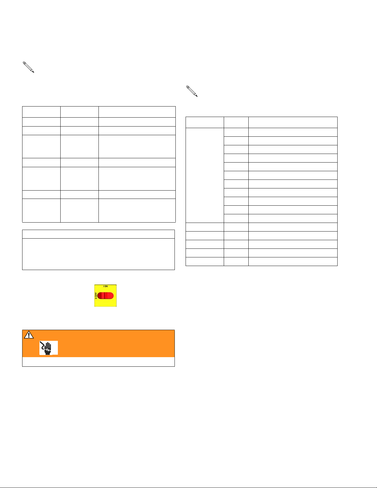
Temperature control board has seven green
LEDs. Power must be on to check. See F
location.
Table 2: Temperature Control Board LEDs
LED Status Function
D26 blinks Board powered
D14 on Zone A turned on
D13 cycles on
and off
D18 on Zone B turned on
D19 cycles on
and off
D27 on Hose zone turned on
D15 cycles on
and off
Before handling board, put on a static conductive wrist
strap to protect against static discharge which can
damage board. Follow instructions provided with wrist
strap.
Zone A powered, LED
cycles as temperature
cycles
Zone B powered, LED
cycles as temperature
cycles
Hose zone powered, LED
cycles as temperature
cycles
CAUTION
IG. 4 for
7. Remove screws and take board off heatsink.
8. Install new board in reverse order. Apply thermal
heatsink compound to mating surfaces of board and
heatsink.
Order Part No. 110009 Thermal Compound.
Table 3: Temperature Control Board Connectors
Connector Pin Description
J1 1, 2 Overtemperature switch A
3, 4 Overtemperature switch B
5, 6 Current sensor
7 Temperature sensor A, red
8 Temperature sensor A, yellow
9 Not used
10 Temperature sensor B, red
11 Temperature sensor B, yellow
12 Thermocouple, silver
13 Thermocouple, red
14 Thermocouple, purple
J2 n/a To A heaters
J5 n/a To display board
J8 n/a Data reporting
J9 n/a To B heaters
J13 n/a To heated hose
1. Turn main power OFF . Disconnect power
supply.
WARNING
Read warnings, page 6.
2. Relieve pressure, page 9.
3. Refer to electrical diagrams. Temperature control
board is on left side inside cabinet.
4. Put on static conductive wrist strap.
5. Disconnect all cables and connectors from board,
F
IG. 4.
6. Remove nuts and take entire temperature control
assembly to workbench.
18 309813H
Page 19
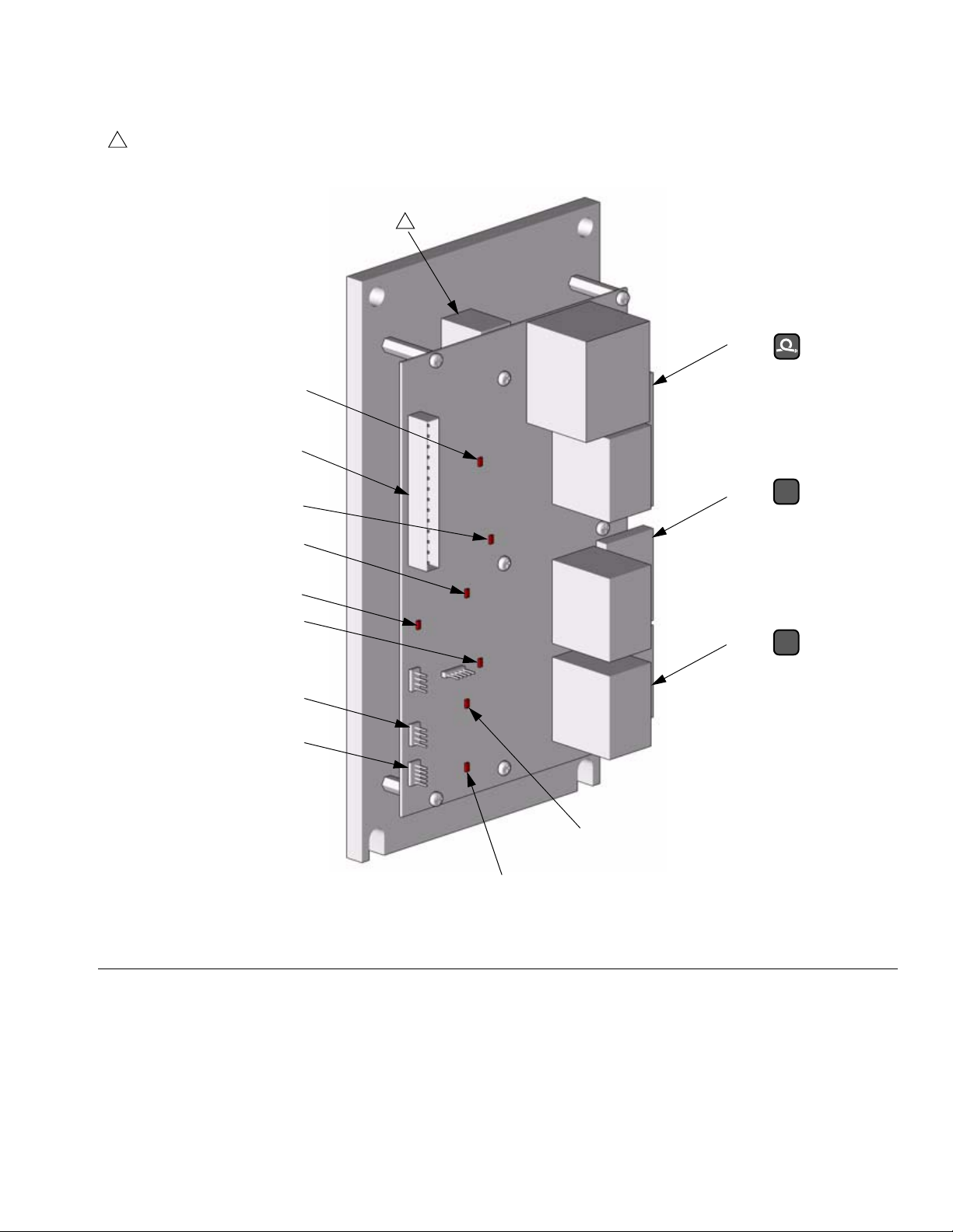
1
Apply 110009 thermal heatsink compound to mating surfaces.
1
D15
J1
D27
J13
J9
Repair
B
D19
D26
D18
J8
J5
FIG. 4. Temperature Control Board
D14
D13
J2
A
TI2572a
309813H 19
Page 20
Repair
Heater
Heater Element
214
W
213205207
1. Turn main power OFF . Disconnect power
supply.
2. Relieve pressure, page 9.
WARNING
Read warnings, page 7. Wait for heaters to cool before
repairing.
3. Wait for heaters to cool.
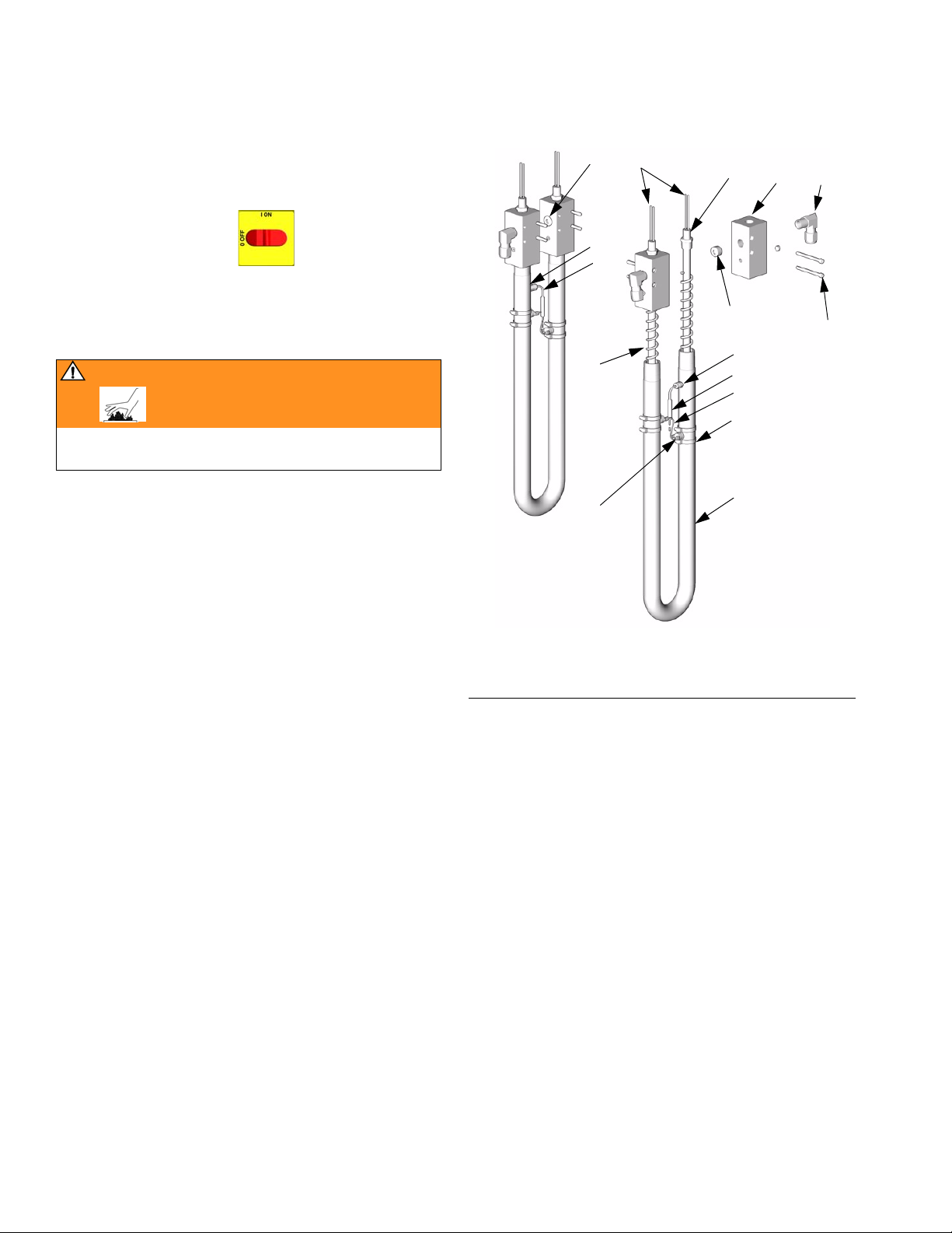
4. See F
5. If heater fails test, remove temperature sensor (211)
6. Remove heater element (207) from tube (201). Be
IG. 5. Remove tape and wire connector (63,
not shown), and disconnect heater element wires
(W) from heater wire harness. Test with ohmmeter.
Resistance must be 21-25 ohms for 2550W element, and 30-34 ohms for 1500W element.
to avoid damage.
careful not to spill any fluid left in tube.
P
211
210
202
208
FIG. 5. Heater (Model 245962 Shown)
206
P
211
182
203
201
TI2512b
7. Install new heater element (207), holding mixer
(202) so it does not interfere with sensor port (P).
8. Reinstall temperature sensor, page 21.
9. Reconnect wires and secure with connector (63)
and electrical tape.
20 309813H
Page 21
Repair
Temperature Sensor
1. Turn main power OFF . Disconnect power
supply.
2. Relieve pressure, page 9.
WARNING
Read warnings, page 7. Wait for heaters to cool before
repairing.
3. Wait for heaters to cool.
4. Disconnect temperature sensor wires from J1 on
temperature control board. See T
and F
IG. 4, page 19.
5. See F
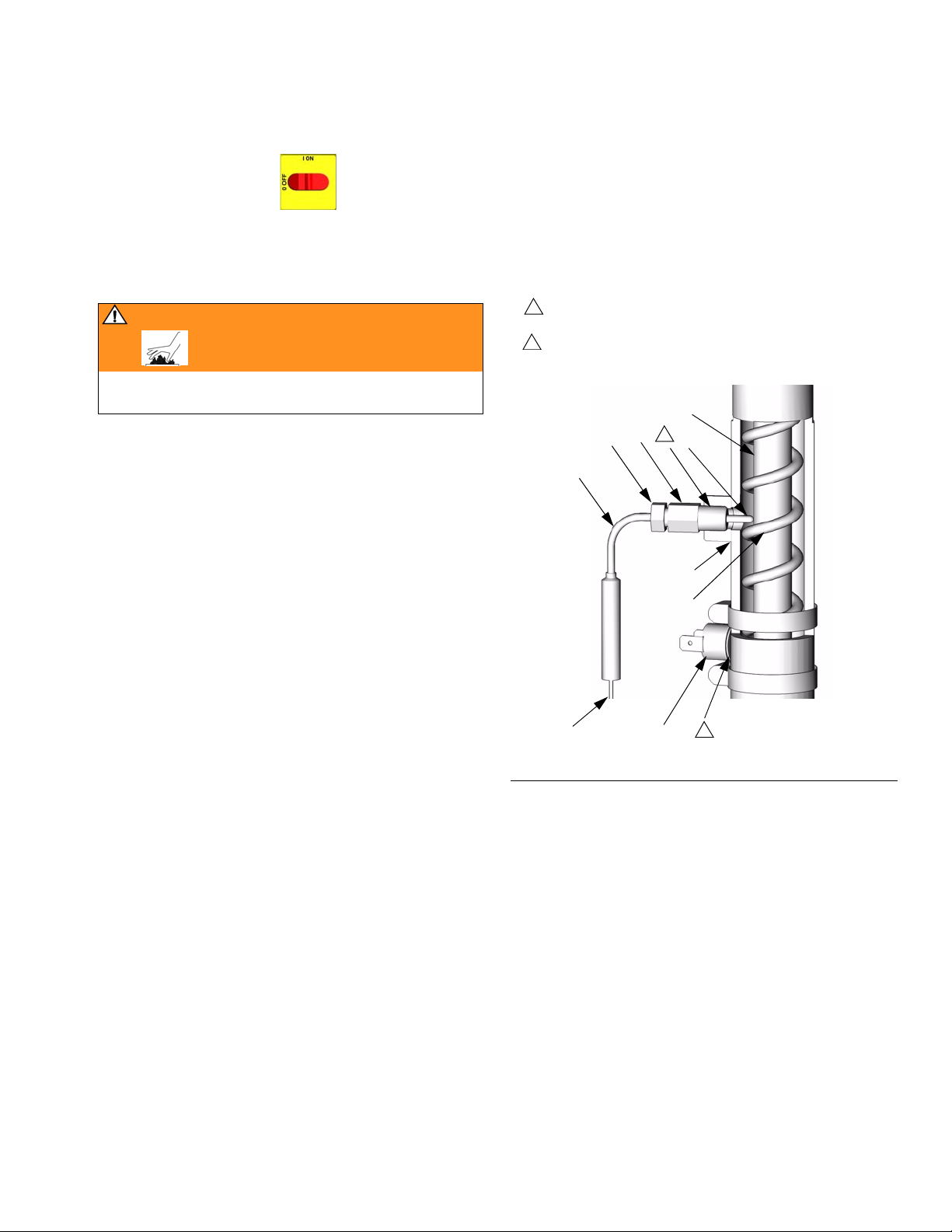
IG. 6. Test with ohmmeter. Between wires (S),
resistance must be approximately 6 ohms. Between
tip (T) and wires, resistance must be infinity (∞).
ABLE 3, page 18
9. Route wires into cabinet and thread into bundle as
before. Reconnect wires to board.
10. Turn on heaters A and B simultaneously to test.
Temperatures should rise at same rate (30°F, +/4°). If one heater is low, loosen ferrule nut (N) and
tighten sensor housing (H) to ensure sensor tip (T)
contacts element (207).
1
Apply PTFE tape and thread sealant.
2
Apply 110009 thermal heatsink compound.
207
NH T
1
211
201
6. If sensor fails test, feed wires out of cabinet. Note
path as cable must be replaced in the same way.
7. Loosen ferrule nut (N). Remove temperature sensor
(211) from heater tube (201), then remove sensor
housing (H).
8. Replace sensor, F
IG. 6.
a. Remove protective tape from sensor tip (T).
b. To ensure mixer (202) is out of the way, insert
1/4 in. drill bit into heater tube (201) to a minimum depth of 0.81 in. (20.6 mm). If minimum is
not achieved, mixer must be moved before proceeding.
c. Apply PTFE tape and thread sealant to male
threads and tighten sensor housing (H) into
tube (201).
d. Push in sensor (211) so tip (T) contacts heater
element (207), avoiding mixer (202).
202
S
208
FIG. 6. Temperature Sensor
2
TI3249a
e. Tighten ferrule nut (N), holding sensor (T)
against heater element.
309813H 21
Page 22
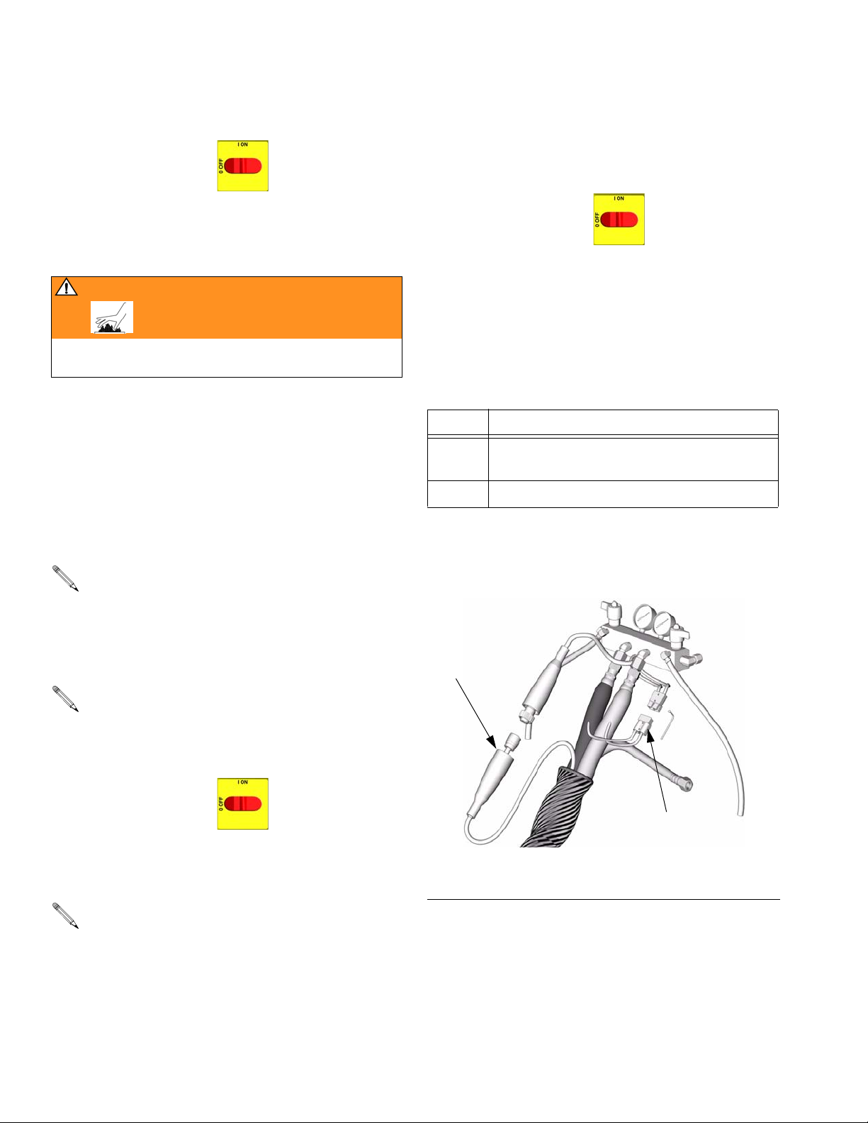
Repair
Overtemperature Switch
1. Turn main power OFF . Disconnect power
supply.
2. Relieve pressure, page 9.
WARNING
Read warnings, page 7. Wait for heaters to cool before
repairing.
3. Wait for heaters to cool.
4. Disconnect one leadwire from overtemperature
switch (208), F
ter. Resistance must be approximately 0 ohms.
5. If switch fails test, cut off clamps with wire clippers.
Remove switch. Install new switch in same location
on tube (201) and secure with hose clamps (203).
Reconnect wires.
IG. 6. Test across switch with ohmme-
5. If hose fails test, retest at each length of hose,
including whip hose, until failure is isolated.
Check FTS Cables
1. Turn main power OFF . Disconnect power
supply.
2. Relieve pressure, page 9.
3. Disconnect FTS cable (F) at Reactor, F
4. Test with ohmmeter between pins of cable connector.
Pins Result
1 to 2 approximately 35 ohms per 50 ft (15.2 m) of
hose, plus approximately 10 ohms for FTS
1 to 3 infinity (∞)
5. If cable fails test, retest at FTS, page 23.
IG. 7.
If wires need replacement, disconnect from temperature control board. See T
F
IG. 4, page 19.
ABLE 3, page 18 and
Heated Hose
Refer to the heated hose manual 309572 for hose
replacement parts.
Check Hose Connectors
1. Turn main power OFF . Disconnect power
supply.
2. Relieve pressure, page 9.
Whip hose must be connected.
3. Disconnect hose electrical connector (D) at Reactor, F
IG. 7.
F
F
IG. 7. Heated Hose
D
TI2726a
4. Using an ohmmeter, check between the two terminals of hose connector (D). There should be continuity.
22 309813H
Page 23
Repair
Fluid Temperature Sensor
(FTS)
Test/Removal
1. Turn main power OFF . Disconnect power
supply.
2. Relieve pressure, page 9.
3. Remove tape and protective covering from FTS (J),
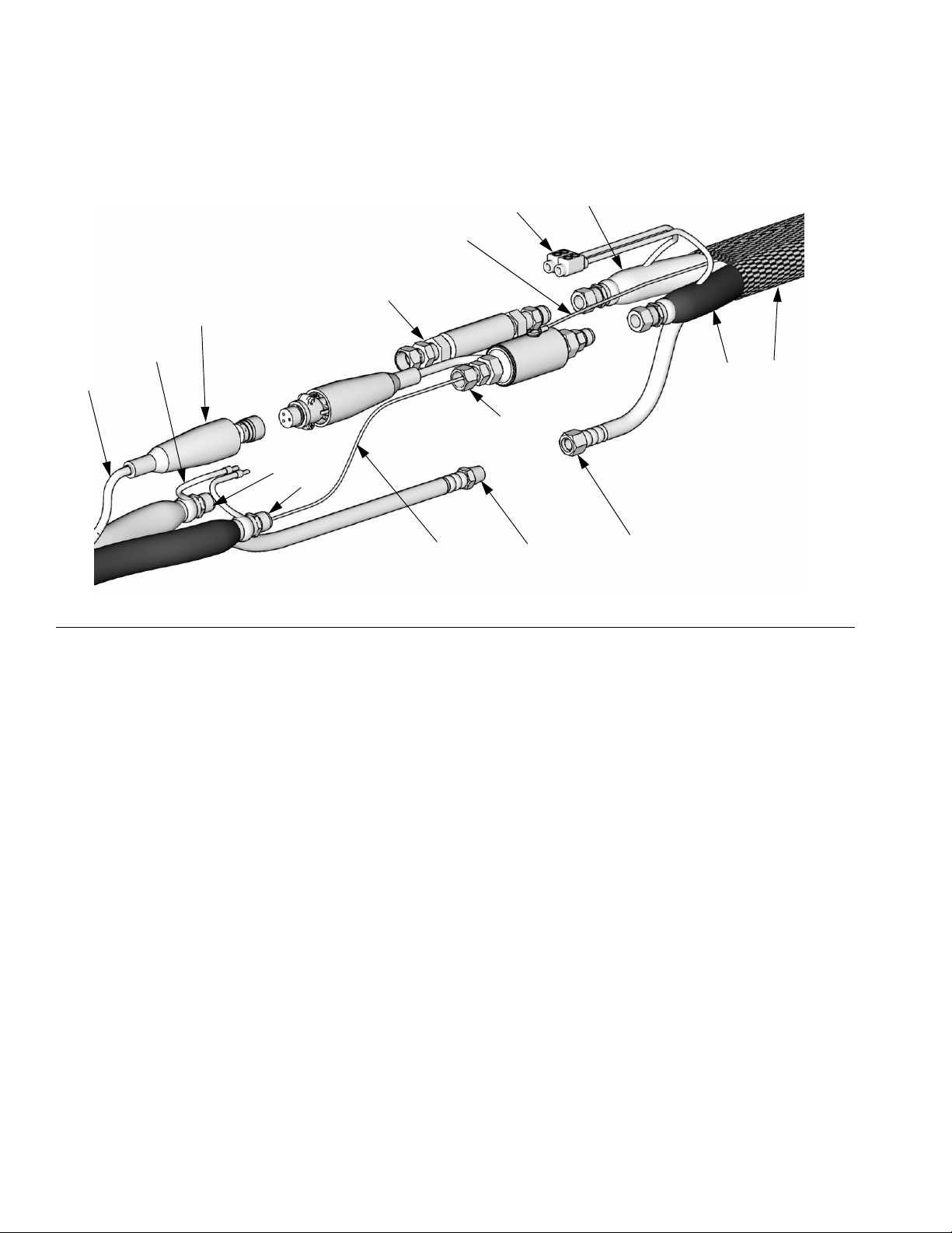
F
IG. 8. Disconnect hose cable (F). Test with ohmme-
ter between pins of cable connector.
Pins Result
1 to 2 approximately 10 ohms
1 to 3 infinity (∞)
3 to FTS groundscrew 0 ohms
2. Connect whip hose ground wire (K) to ground screw
on underside of FTS.
3. Install FTS in reverse order of removal. Leave slack
in cables (G) as stress relief, to prevent cable failure.
4. Secure hose and cable connections with tape and
install protective covering.
1 to FTS component A
fitting (ISO)
4. If FTS fails test, replace FTS.
5. Disconnect air hoses (C, L), and electrical connectors (D).
6. Disconnect FTS from whip hose (W) and fluid hoses
(A, B).
7. Remove ground wire (K) from ground screw on
underside of FTS.
8. Remove FTS probe from component A (ISO) side of
hose.
infinity (∞)
Installation
CAUTION
To prevent damage to probe, do not kink or excessively bend whip hose. Do not coil hose tighter than
the minimum bend radius of 3 ft (0.9 m). Do not subject hose to excessive weight, impact, or other abuse.
1. Carefully extend FTS probe (H). Do not bend or kink
probe. Insert in component A (ISO) side of main
hose.
309813H 23
Page 24
Repair
11
J
F
D
G
B
A
FIG. 8. Fluid Temperature Sensor and Heated Hoses
D
B
K
W
A
ISO
H
C
L
TI9581B
24 309813H
Page 25

Transformer
Repair
Test Hose Continuity
1. Turn main power OFF . Disconnect power
supply. Leave hose plugged in.
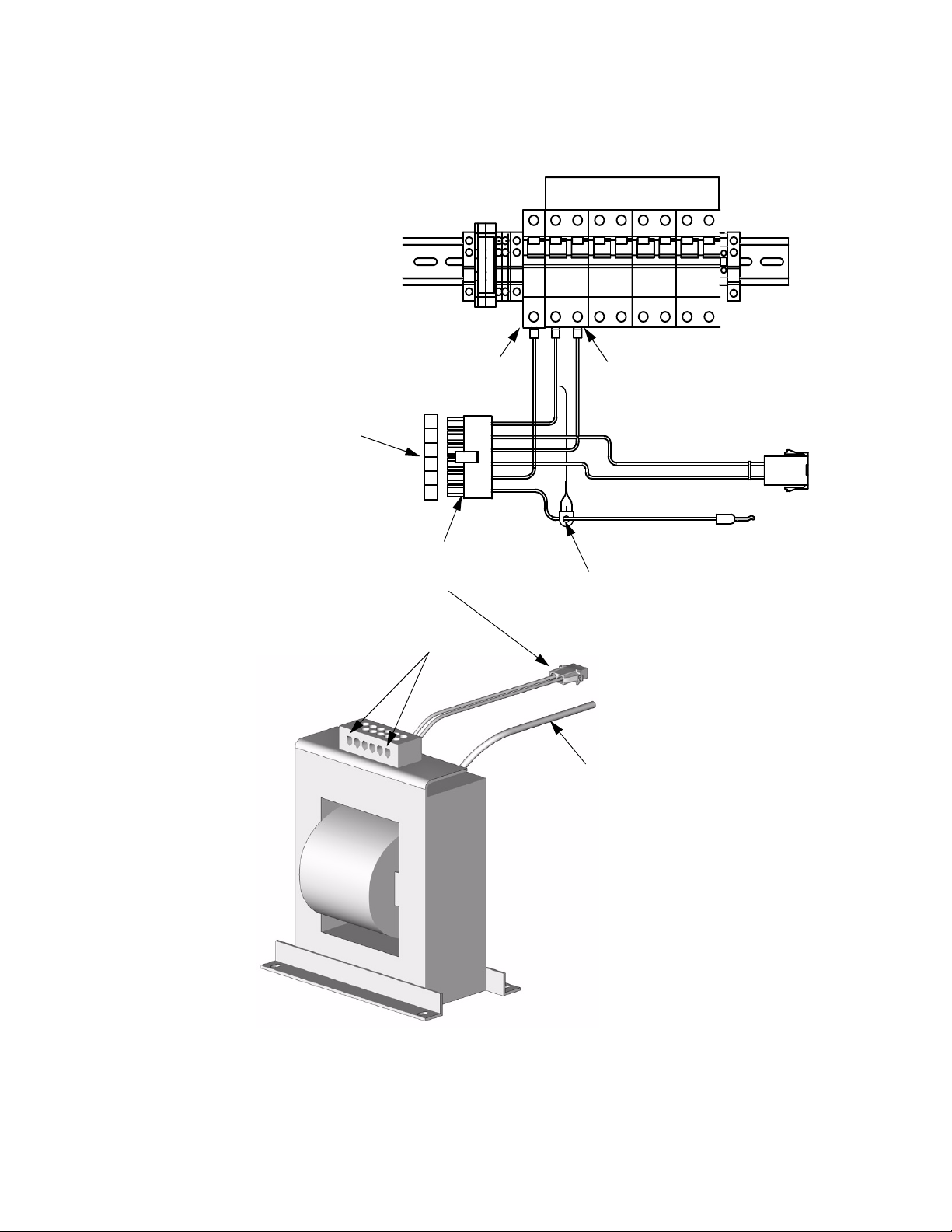
2. See FIG. 9. Disconnect 6-pin transformer connector
(P) from J13 at temperature control board. Remove
red wire from transformer hose length tap you are
using (R).
3. Using an ohmmeter, check between pin 6 (P6) of
connector (not board) and red wire. There should be
continuity.
4. If test fails, trace wires until failure is located.
Test Transformer Wire Harness Continuity
1. Turn main power OFF . Disconnect power
supply. Leave hose plugged in.
3. Using an ohmmeter, test for continuity across pins 5
and 6 of connector (not board). Reading should be
20-25 ohms. If not, replace current sensor (32). See
F
IG. 9.
2. See FIG. 9. Disconnect 6-pin transformer connector
(P) from J13 at temperature control board.
3. Check for continuity between:
a. Connector pin 1 (P1) and T1 on 20A hose circuit
breaker (817A).
b. Connector pin 3 (P3) and T2 on 20A hose circuit
breaker (817A).
c. Connector pin 5 (P5) and T3 on 50A hose circuit
breaker (806).
Test Current Sensor Continuity
1. Turn main power OFF . Disconnect power
supply.
2. Disconnect 14-pin connector from J1 on temperature control board, page 18.
309813H 25
Page 26
Repair
Detail B: Circuit Breaker Module and Hose Heat Wire Harness
To J1 Connector, pins 5 and 6
T1 T2
T3
806 817A
J13 on Temperature
Control Board
P1
P2
P3
P4
P5
P6
P
C
R
32
TI4335A
P
TI3470b
FIG. 9. Transformer Continuity Tests
26 309813H
Page 27
Repair
In-Rush Current Limiter Check
(380V only)
1. Ensure that all harnesses, cables, and connectors
are properly connected. Connect hose
2. Connect power supply. Turn main power ON
.
3. Turn on hose heat by pressing hose heat button
.
4. Contactor on front of transformer should close.
5. If contactor does not close, turn off main power and
check inline fuse (198) on side of contactor. Replace
fuse if blown.
6. If contactor does not close when hose heat is turned
on with a new fuse, begin Transformer Checks.
7. If fuse (198) continually blows, replace In-Rush Current Limiter (288359).
5. See FIG. 9, Detail B. Measure voltage across P2 and
P4 on six-pin connector on temperature control
board. Measurement should be line voltage. If not,
replace temperature control board, page 18.
Transformer Secondary Check
1. Ensure that all harnesses, cables, and connectors
are properly connected. Connect hose.
2. Connect power supply. Turn main power ON
.
3. Set hose heat target temperature below current
hose temperature.
4. Turn on heat zone by pressing .
Transformer Primary Check
1. Ensure that all harnesses, cables, and connectors
are properly connected. Connect hose.
2. Connect power supply. Turn main power ON
.
3. Set hose heat target temperature below current
hose temperature.
4. Turn on heat zone by pressing .
WARNING
Read warnings, page 6. Step 5 measures line voltage
and should be done by a qualified electrician. If work is
not performed properly it may cause electric shock or
other serious injury.
WARNING
Read warnings, page 6. Step 5 measures line voltage
and should be done by a qualified electrician. If work is
not performed properly it may cause electric shock or
other serious injury.
5. See F
IG. 10, Detail B. Measure voltage across trans-
former hose tap (R) you are using and top terminal
(T4) on 50A hose circuit breaker (806). See T
for readings. If reading is correct, replace temperature control board, page 18. If reading is wrong,
replace transformer, page 28.
Table 4: Transformer Voltage Readings
Transformer Tap Reading (VAC)
50’ 20
100’ 34
150’ 48
200’ 62
250’ 76
300’ 90
ABLE 4
309813H 27
Page 28
Repair
Replace Transformer
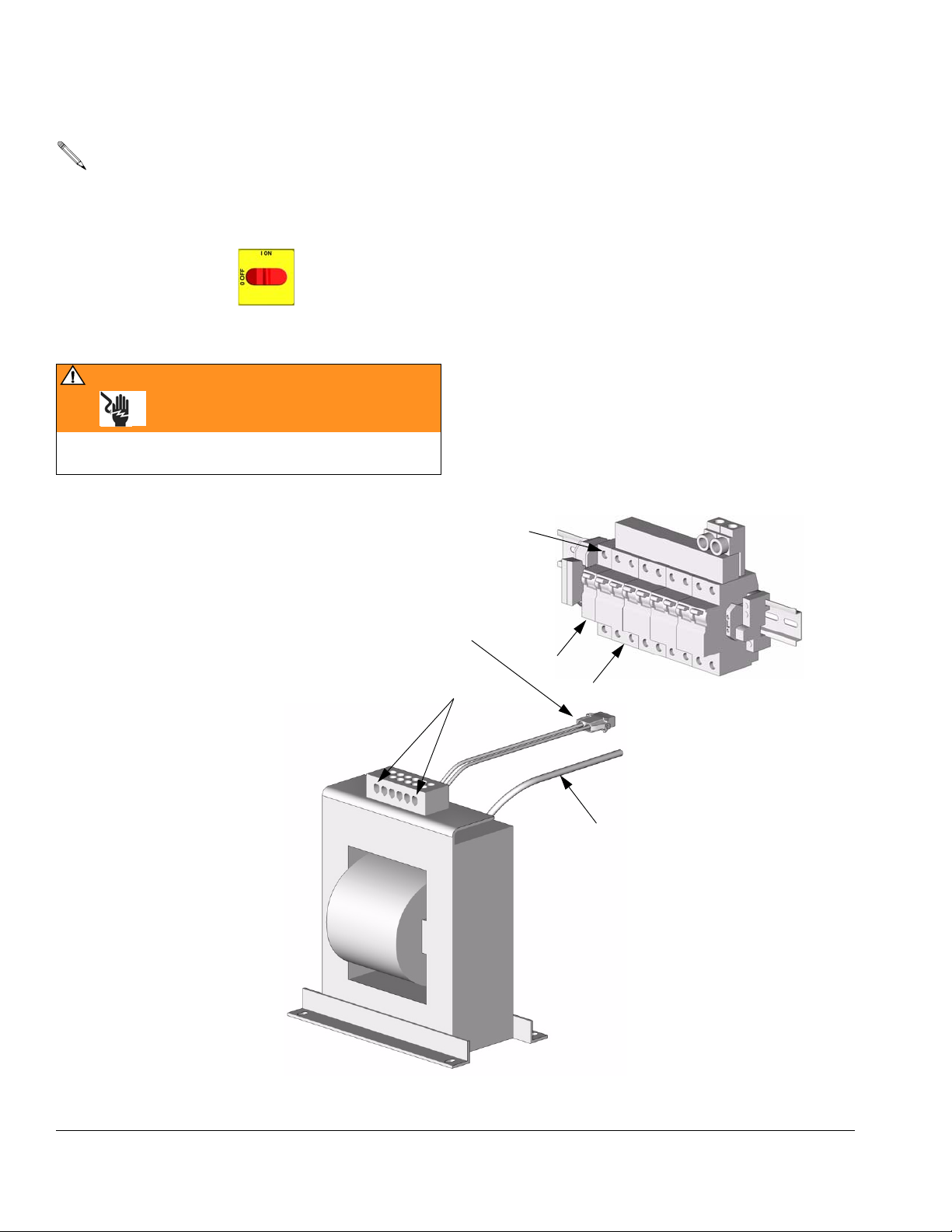
Use this procedure to replace transformer. To
replace terminal block (B) and wire harness (C)
only, order Part No. 248113 Transformer Repair
Kit. See manual 309930.
1. Turn main power OFF . Disconnect power
supply.
WARNING
Read warnings, page 6. Wait 5 min for stored voltage
to discharge (E-30 and E-XP2 models only).
2. Open Reactor cabinet.
3. Remove bolts holding transformer to cabinet floor.
Slide transformer forward.
4. Unplug 2-pin wire harness connector (C) from wire
harness coming from temperature control board.
5. Disconnect the transformers secondary common
wire (P) from T4 at 50 amp circuit breaker (806).
6. Remove transformer from cabinet.
7. Install new transformer in reverse order.
Detail B: Circuit Breaker Module
T4
C
806
R
817A
TI2514A
P
TI3470b
FIG. 10. Transformer
28 309813H
Page 29
Repair
Display Module
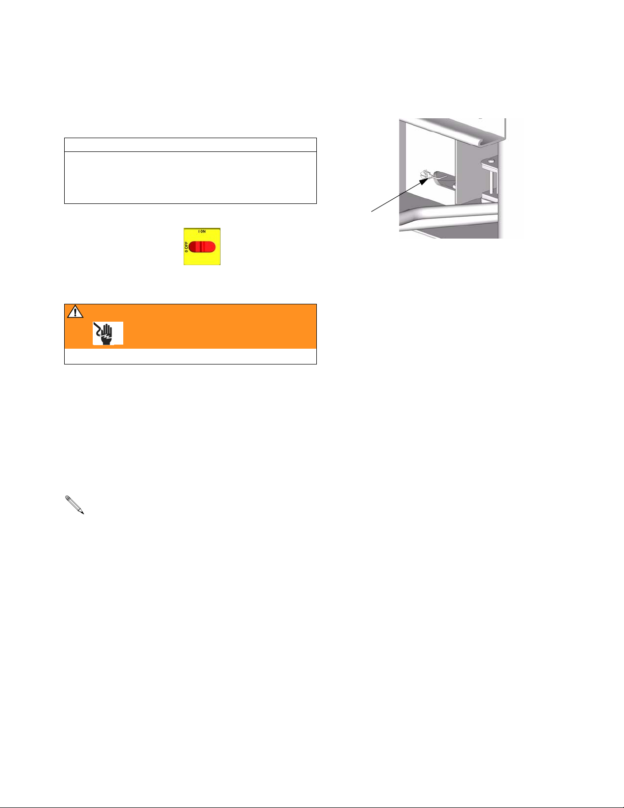
Temperature and Cycle Counter Displays
CAUTION
Before handling board, put on a static conductive wrist
strap to protect against static discharge which can
damage board. Follow instructions provided with wrist
strap.
1. Turn main power OFF . Disconnect power
supply.
WARNING
Read warnings, page 6.
(412), F
IG. 11. Also check ground connection at rear
of Reactor, see below.
G
TI2603a-2
2. Relieve pressure, page 9.
3. Refer to electrical diagrams.
4. Put on static conductive wrist strap.
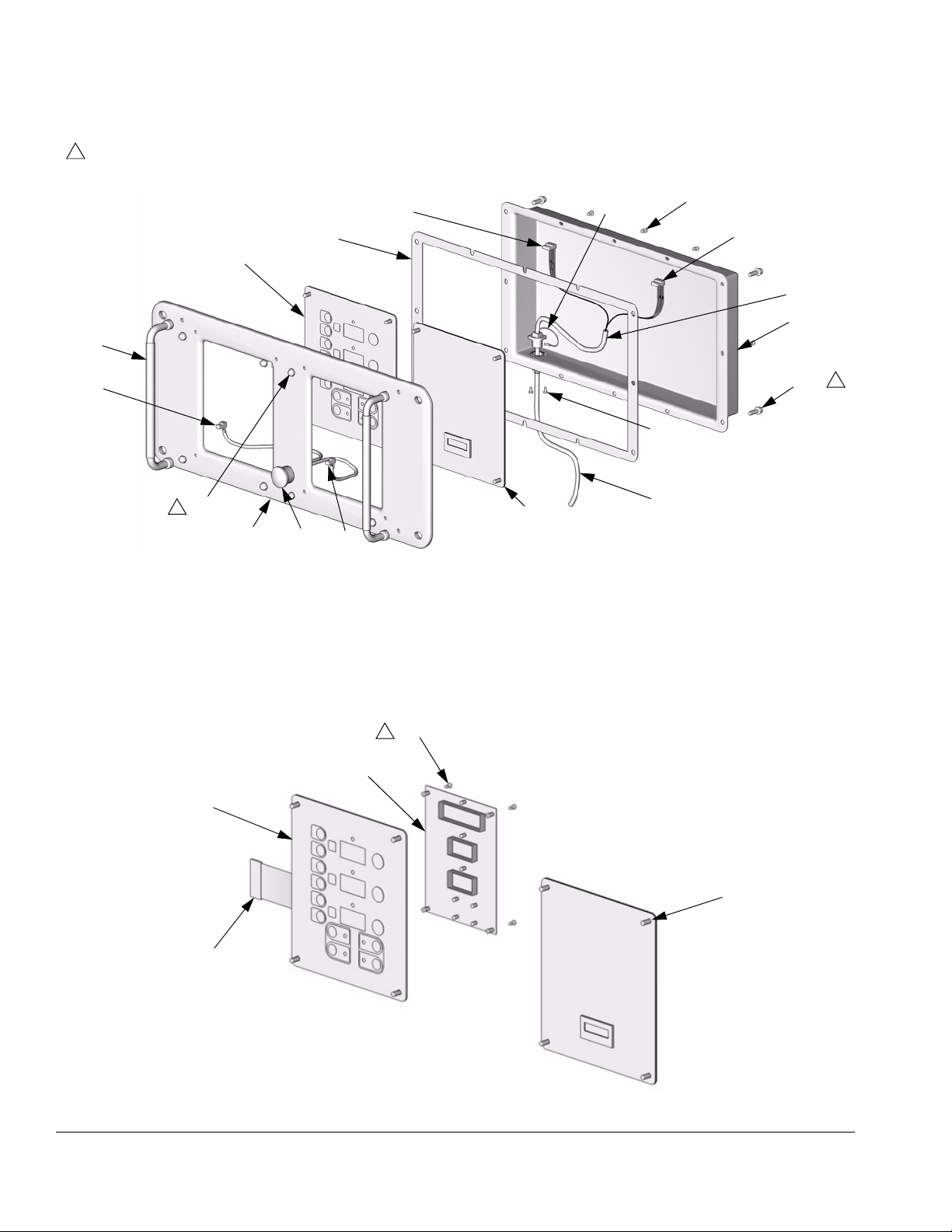
5. Disconnect main display cable (120) at lower left
corner of display module, F
IG. 11.
6. Remove screws (409, 410) and cover (404).
If replacing both displays, label temperature display cables TEMP and cycle counter display
cables CYCLES before disconnecting.
7. Disconnect cable connectors J1 and J13 from back
of temperature display (402) or cycle counter display (401).
8. Disconnect ribbon cable (R) from back of display.
9. Remove nuts (408) and plate (405).
10. Disassemble display, see detail in F
IG. 11.
11. Replace board (401 or 402a) or membrane switch
(402b) as necessary.
12. Reassemble in reverse order, see F
IG. 11. Apply
medium strength thread sealant where shown. Be
sure display cable ground wire (G) is secured
between cable bushing and cover (404) with screws
309813H 29
Page 30
Repair
1
Apply medium strength thread sealant.
407
J1
409
J13
403
J13
G
402
411
404
410
1
412
408
1
405
406
J1
401
120
TI3703a
Detail of Membrane Switches and Display Boards
402b
R
FIG. 11. Display Module
Temperature Display Cycle Counter Display
402c
1
402a
401
TI3702a
30 309813H
Page 31
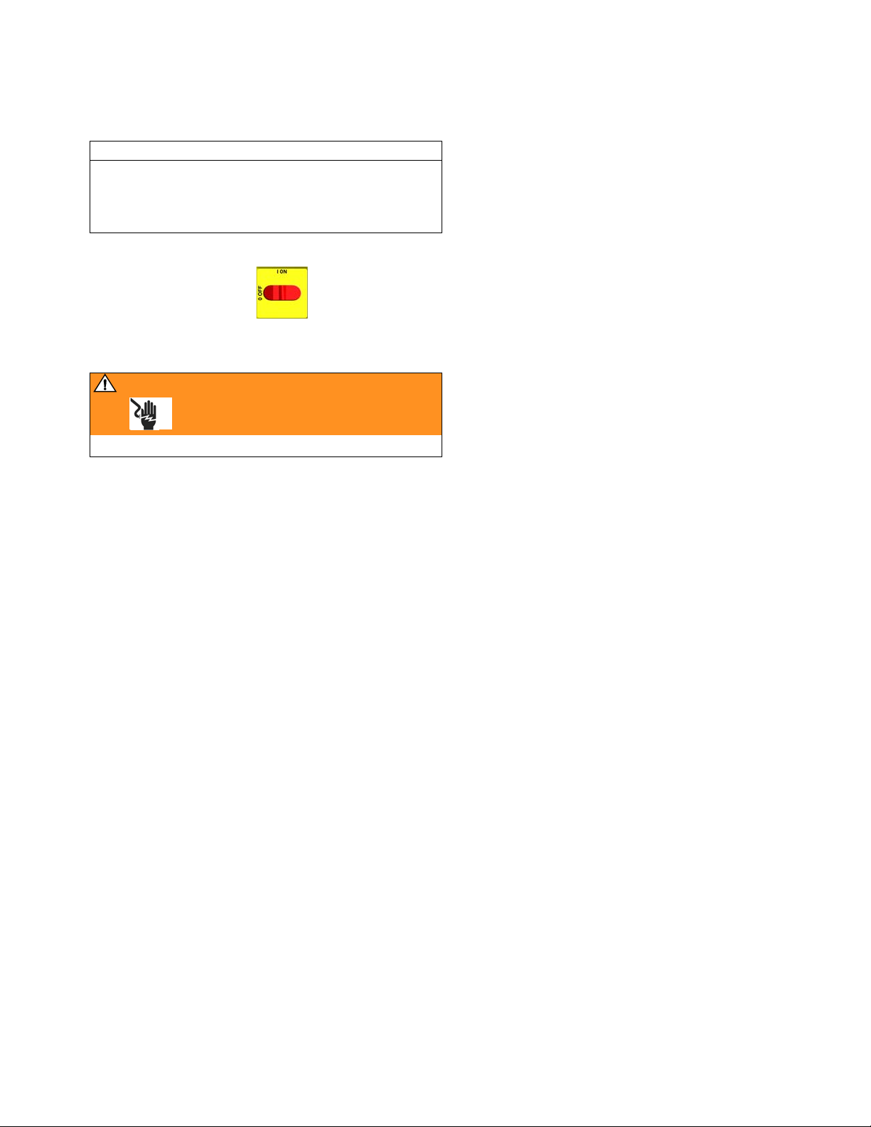
Red Stop Button
CAUTION
Before handling board, put on a static conductive wrist
strap to protect against static discharge which can
damage board. Follow instructions provided with wrist
strap.
1. Turn main power OFF . Disconnect power
supply.
WARNING
Read warnings, page 6.
Repair
2. Relieve pressure, page 9.
3. Refer to electrical diagrams.
4. Put on static conductive wrist strap.
5. Remove screws (409, 410) and cover (404), F
IG. 11.
6. Disconnect button cable connectors J1 from back of
temperature display (401) and cycle counter display
(402).
7. Remove red stop button (406).
8. Reassemble in reverse order. Be sure display cable
ground wire (G) is secured between cable bushing
and cover (404) with screws (412).
309813H 31
Page 32
Parts
Parts
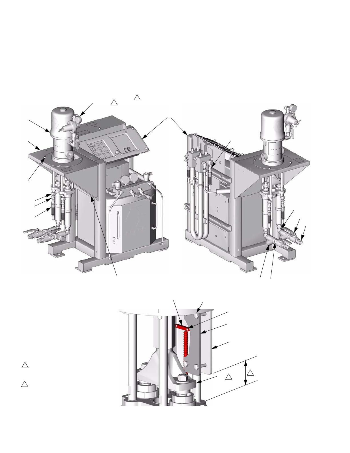
Air Powered Reactors (Model A-XP2 Shown)
1
15, 25
1
Ref. No. 25 used on A-50 Models only.
Not shown in this view.
6
2
7, 8, 9
17
20
31
3, 4, 5
TI3669b
1
16
10
14
13
TI3704b
12
11
27, 37 28, 29
30, 44
38
18
Detail of Cycle Counter Switch
2
Ref. No. 26 Magnet is on back side of yoke.
26
2
3
Dimension from bottom of switch mounting
plate (18) to top of tie plate must be 2 in.
(51 mm) to maintain correct relationship
between magnet (26) and switch (27).
32 309813H
TI3701a
3
Page 33
Parts
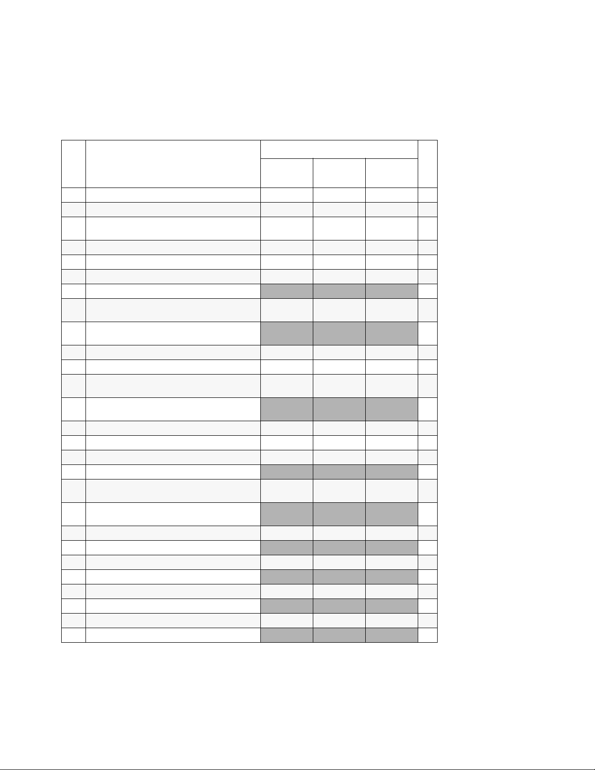
Air Powered Reactors
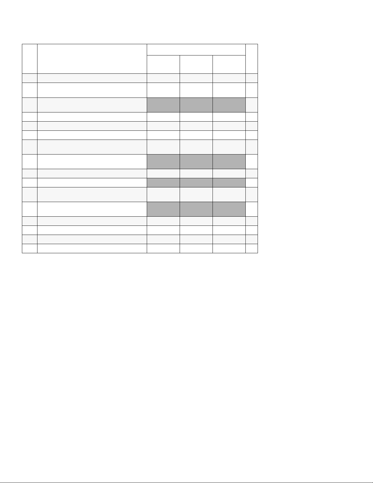
Use this chart to find parts by model. Find ref. no. of part in left column, and Reactor model in top row. Intersection is
correct part no.
Air Powered Reactor Models
Ref.
No. Description
1 PACKAGE, control, heat; page 35 246607 246762 246763 1
2 BRACKET, mounting 217298 217298 217298 1
3 SCREW, cap; 1/2-13 x 3-1/2 in.
(89 mm)
4 WASHER, lock; 1/2 in. 100018 100018 100018 4
5 NUT, hex; 1/2-13 100321 100321 100321 4
6 PUMP, proportioner; see 308224 231646 231646 231646 1
PUMP, proportioner; see 307547
7 SCREW, cap; 3/8-16 x 1 in.
(25 mm)
SCREW, cap; 3/8-16 x 2 in.
(51 mm)
8 WASHER, lock; 3/8 in. 100133 100133 100133 4
9 NUT, hex; 3/8-16 100131 100131 100131 4
10 ELBOW, swivel; 3/4 npt(m) x
3/4 npt(f)
ELBOW, swivel; 1 in. npt(m) x
1 in. npsm(f)
11 Y-STRAINER; includes 11a 101078 101078 101078 2
11a . ELEMENT, 20 mesh; not shown 180199 180199 180199 1
12 NIPPLE; 3/4 npt C20487 C20487 C20487 2
NIPPLE; 1 in. npt
13 UNION, swivel; 3/4 npt(m) x
3/4 npt(f)
UNION, swivel; 1 in. npt(m) x
1 in. npsm(f)
14 VALVE, ball; 3/4 npt (fbe) 109077 109077 109077 2
VALVE, ball; 1 in. npt (fbe)
15 KIT, air control; see 308168 241661 241661 241661 1
KIT, air control; see 308168
16 SWIVEL; 1/2 npt(m) x 3/8 npsm(f) 158256 158256 158256 2
NIPPLE; 1/2 npt
17 ELBOW, street; 3/8 npt (mxf) 155699 155699 155699 2
ELBOW, street; 1/2 npt (mxf)
246639
A-XP2
100679 100679 100679 4
100101 100101 100101 4
160327 160327 160327 2
157785 157785 157785 2
246752
A-XP2
246753
A-XP2
Qty
1
4
2
2
2
2
1
2
2
309813H 33
Page 34
Parts
Air Powered Reactor Models
Ref.
No. Description
18 PLATE, mounting, switch 15C256 15C256 15C256 1
20 UNION, swivel; 3/8 npt(m) x
3/8 npsm(f)
25 VALVE, air relief; 75 psi (0.5 MPa,
5 bar)
26 MAGNET 116618 116618 116618 1
27 SWITCH, reed, with cable 117770 117770 117770 1
28 NUT, hex flange; 1/4-20 115942 115942 115942 4
29 SCREW, cap, hex hd; 1/4-20 x 1-3/4 in. (44
mm)
SCREW, cap, hex hd; 1/4-20 x
2 in. (51 mm)
30 SCREW, machine; 5-40 x 7/8 in. (22 mm) 107438 107438 107438 2
SCREW, machine; 5-40 x 1/2 in. (13 mm)
31 HOSE, fluid; nylon; 3/8 npt (mbe); 3/8 in. (10
mm) ID; 5 ft (1.52 m)
HOSE, fluid; nylon; 1/2 npsm (fbe); 3/8 in.
(10 mm) ID; 5 ft (1.52 m)
36 OIL, ISO pump; not shown 217374 217374 217374 1
37 CONNECTOR, 5 pin; 24 AWG 118115 118115 118115 1
38 BRACKET, mounting, switch 15C319 15C319 15C319 1
44 SPACER 116374 116374 116374 2
246639
A-XP2
155665 155665 155665 2
106485 106485 106485 4
215247 215247 215247 2
246752
A-XP2
246753
A-XP2
Qty
1
4
2
2
34 309813H
Page 35
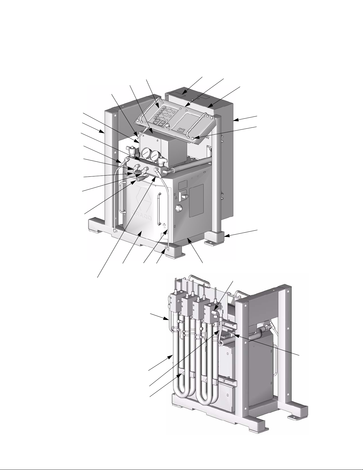
Heat Control Package
Parts
109, 124, 125
101
148
189
186
137
187
119
120
106
153
192
104
159
158
140
117
110
107, 112, 141
170, 196, 197, 172
TI3707a
103190, 191138
122
116
113, 126, 135
102
114
TI3708b
309813H 35
Page 36
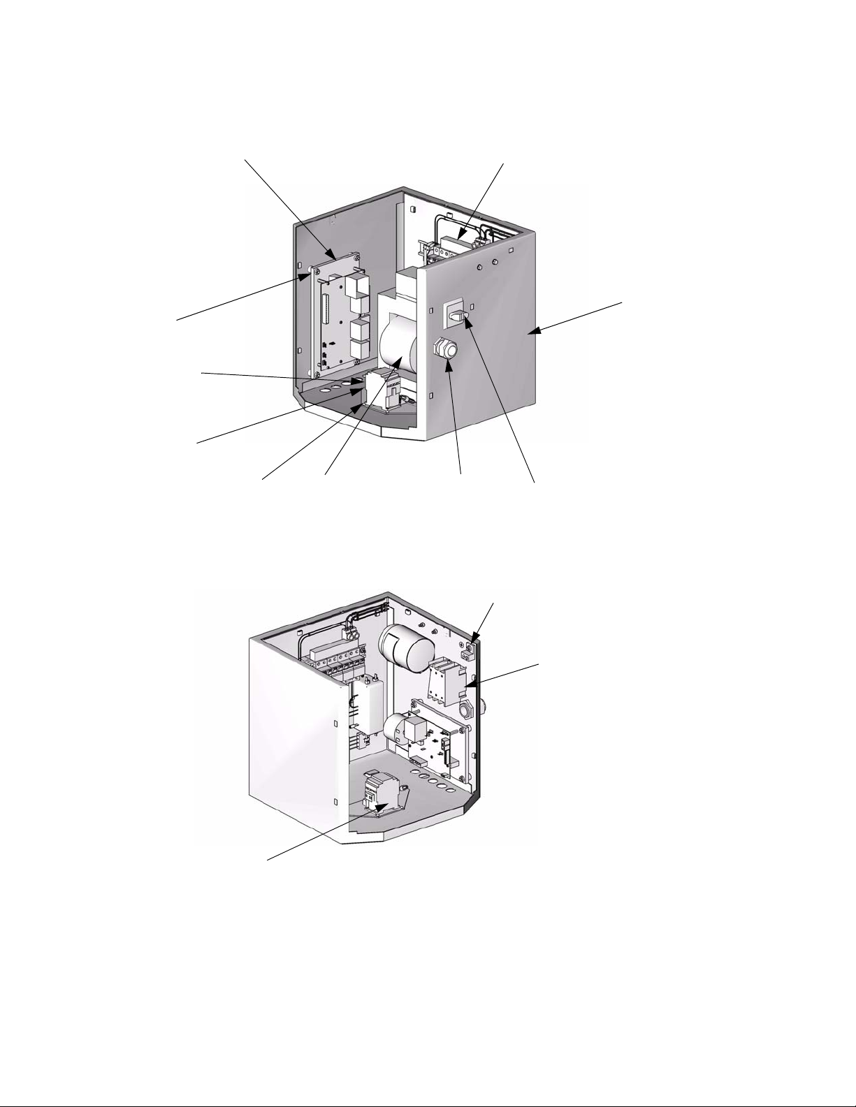
Parts
129, 142
*In-rush current
limiter 288359 is
included only on
380V machines.
See page 39 for
fuse information.
105
*198
*199
141, 123, 130
108
128, 161, 162
127
160
TI2606b
134
198, 199
380V models only
131
133, 194
TI3705B
36 309813H
Page 37
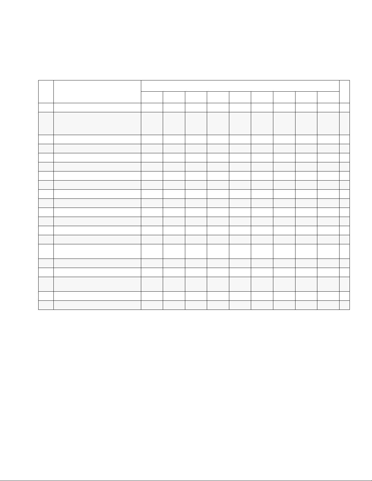
Parts
Heat Control Package
Use the following chart to find parts that vary by package. Find the ref. no. of part in left column, and package in top
row. Intersection is correct part no.
Ref.
No. Description
101 FRAME 245955 245955 245955 245955 245955 245955 245955 245955 245955 1
102 HEATER; pages 40, 41 245963
103 ENCLOSURE, electronics 15C220 15C220 15C220 15C220 15C220 15C220 15C220 15C220 15C220 1
104 DISPLAY; page 42 246043 246043 246043 246043 246043 246043 246043 246043 246043 1
105 CONTROL, temperature; page 43 245979 245979 245979 245979 245979 245979 245979 245979 245979 1
106 COVER, fan 15C223 15C223 15C223 15C223 15C223 15C223 15C223 15C223 15C223 1
107 MANIFOLD, fluid; page 44 246042 246042 246042 246042 246042 246042 246042 246042 246042 1
108 TRANSFORMER; see page 48 15B352 15B352 15B352 15B352 15B352 15B352 15B352 15B352 15B352 1
109 COVER, wire access 15B775 15B775 15B775 15B775 15B775 15B775 15B775 15B775 15B775 1
110 DOOR, cabinet 246976 246976 246976 246976 246976 246976 246976 246976 246976 1
111 SENSOR, fluid temperature 261669 261669 261669 261669 261669 261669 261669 261669 261669 1
112 GASKET, manifold 15B456 15B456 15B456 15B456 15B456 15B456 15B456 15B456 15B456 1
113 FAN 115834 115834 115834 115834 115834 115834 115834 115834 115834 1
114 TUBE, heater, component A 15B685 15B481 15B481 15B481 15B481 15B481 15B481 15B685 15B685 1
115 SCREW, machine; 8-32 x 0.345 in.
(9 mm)
116 TUBE, heater, component B 15B687 15B483 15B483 15B483 15B483 15B483 15B483 15B687 15B687 1
117 CAP, square 168422 168422 168422 168422 168422 168422 168422 168422 168422 6
118 CABLE, overtemperature; not
shown, see electrical diagrams
119 CABLE, hose control 15B380 15B380 15B380 15B380 15B380 15B380 15B380 15B380 15B380 1
120 CABLE, display 15B383 15B383 15B383 15B383 15B383 15B383 15B383 15B383 15B383 1
246364 246365 246607 246760 246761 246762 246763 246764 246765
(qty: 2)
115492 115492 115492 115492 115492 115492 115492 115492 115492 2
15B374 15B374 15B374 15B374 15B374 15B374 15B374 15B374 15B374 1
245975
(qty: 1)
245962
(qty: 1)
Heat Control Package
245975
(qty: 1)
245975
(qty: 1)
245962
(qty: 1)
245962
(qty: 1)
245963
(qty: 2)
245963
(qty: 2)
Qty
or
1
2
309813H 37
Page 38

Parts
Ref.
No. Description
122 ELBOW, street; 1/2 npt (mxf) 158683 158683 158683 158683 158683 158683 158683 158683 158683 2
123 NUT, hex flange; 3/8-16 112958 112958 112958 112958 112958 112958 112958 112958 112958 4
124 BOOT, wire feed through 15B361 15B361 15B361 15B361 15B361 15B361 15B361 15B361 15B361 1
125 PLATE, cover, wire 15B510 15B510 15B510 15B510 15B510 15B510 15B510 15B510 15B510 1
126 GASKET, fan 15B360 15B360 15B360 15B360 15B360 15B360 15B360 15B360 15B360 1
127 STRAIN RELIEF 117682 117682 117682 117682 117682 117682 117682 117682 117682 1
128 MODULE, breaker; page 45 246092 246090 246090 246087 246096 246087 246096 246089 246098 1
129 SPACER 116149 116149 116149 116149 116149 116149 116149 116149 116149 4
130 SCREW, cap; 3/8-16 x 5/8 in. (16
mm)
131 TERMINAL, ground 117666 117666 117666 117666 117666 117666 117666 117666 117666 1
132 SENSOR, current, hose; not
shown, see electrical diagrams
133 SWITCH, disconnect 117564 117564 117564 117564 117564 117564 117564 117564 117564 1
134 SWITCH, main power 117545 117545 117545 117545 117545 117545 117545 117545 117545 1
135 SCREW, machine; 6-32 x 2 in.
(51 mm)
137 WIRE, hose 15B396 15B396 15B396 15B396 15B396 15B396 15B396 15B396 15B396 1
138 TUBE; 1/4 in. (6 mm) ID; 3/8 in. (16
mm) OD; 2 ft (1.2 m); PTFE
140 NUT, cap; 3/8-16 117623 117623 117623 117623 117623 117623 117623 117623 117623 4
141 SCREW, cap; 1/4-20 x 3/4 in. (19
mm)
142 NUT, hex flange; 1/4-20 115942 115942 115942 115942 115942 115942 115942 115942 115942 7
148▲LABEL, caution 189285 189285 189285 189285 189285 189285 189285 189285 189285 3
246364 246365 246607 246760 246761 246762 246763 246764 246765
100575 100575 100575 100575 100575 100575 100575 100575 100575 4
15B388 15B388 15B388 15B388 15B388 15B388 15B388 15B388 15B388 1
117723 117723 117723 117723 117723 117723 117723 117723 117723 4
buy
locally
113796 113796 113796 113796 113796 113796 113796 113796 113796 7
buy
locally
buy
locally
Heat Control Package
buy
locally
buy
locally
buy
locally
buy
locally
buy
locally
Qty
buy
locally
1
153 SHIELD, membrane switch;
pack of 10
158 COVER, heater, back 15B797 15B797 15B797 15B797 15B797 15B797 15B797 15B797 15B797 1
159 COVER, heater, front 15B798 15B798 15B798 15B798 15B798 15B798 15B798 15B798 15B798 1
160▲LABEL, warning 15B679 15B679 15B679 15B679 15B679 15B679 15B679 15B679 15B679 1
38 309813H
15B593 15B593 15B593 15B593 15B593 15B593 15B593 15B593 15B593 1
Page 39

Parts
Ref.
No. Description
161 NUT, hex, keps; 10-24 113505 113505 113505 113505 113505 113505 113505 113505 113505 6
162 WASHER, plain; no. 10 112776 112776 112776 112776 112776 112776 112776 112776 112776 2
163 CONNECTOR, wire; not shown,
see electrical diagrams
170 BOLT; 3/8-16 516595
172 CLAMP, pipe, heater 15C733
179 FERRULE 112512 112512 112512 112512 112512 112512 112512 112512 112512 2
180 ELBOW; 1/2 npt x 1/2 in. (13 mm)
OD tube
182 CABLE, overtemperature, jumper 15B769
183 WASHER, lock; 1/4 100016 100016 100016 100016 100016 100016 100016 100016 100016 15
184 WASHER, plain; 3/16 100086 100086 100086 100086 100086 100086 100086 100086 100086 8
186 REDUCER; #5 x #8 JIC 117502 117502 117502 117502 117502 117502 117502 117502 117502 1
187 REDUCER; #6 x #10 JIC 117677 117677 117677 117677 117677 117677 117677 117677 117677 1
189 COUPLING, hose; 1/4 npsm(f) 205447 205447 205447 205447 205447 205447 205447 205447 205447 2
190 BRACKET, holding 15C447 15C447 15C447 15C447 15C447 15C447 15C447 15C447 15C447 2
191 SCREW, machine; 5-40 x 1/2 in.
(13 mm)
192 LABEL, diagnostic codes 15C477 15C477 15C477 15C477 15C477 15C477 15C477 15C477 15C477 1
194 SWITCH, added pole; 380V
195▲LABEL, warning;
246364 246365 246607 246760 246761 246762 246763 246764 246765
117722 117722 117722 117722 117722 117722 117722 117722 117722 4
(qty: 4)
(qty: 4)
117532 117532 117532 117532 117532 117532 117532 117532 117532 2
(qty: 4)
100974 100974 100974 100974 100974 100974 100974 100974 100974 2
171001 171001 171001 171001 171001 171001 171001 171001 171001 1
516595
(qty: 2)
15C733
(qty: 2)
15B769
(qty: 2)
516595
(qty: 2)
15C733
(qty: 2)
15B769
(qty: 2)
Heat Control Package
516595
(qty: 2)
15C733
(qty: 2)
15B769
(qty: 2)
516595
(qty: 2)
15C733
(qty: 2)
15B769
(qty: 2)
117553 117553 117553 1
516595
(qty: 2)
15C733
(qty: 2)
15B769
(qty: 2)
516595
(qty: 2)
15C733
(qty: 2)
15B769
(qty: 2)
516595
(qty: 4)
15C733
(qty: 4)
15B769
(qty: 4)
516595
(qty: 4)
15C733
(qty: 4)
15B769
(qty: 4)
Qty
or
or
or
2
4
2
4
2
4
196 WASHER, lock; 3/8 in. 100133
(qty: 4)
197 NUT; 3/8-16 118446
(qty: 4)
198* FUSE,1.6A, Slo-Blow 120614 120614 120614 1
199 IN-RUSH CURRENT LIMITER 288359 288359 288359 1
100133
(qty: 2)
118446
(qty: 2)
100133
(qty: 2)
118446
(qty: 2)
100133
(qty: 2)
118446
(qty: 2)
100133
(qty: 2)
118446
(qty: 2)
100133
(qty: 2)
118446
(qty: 2)
100133
(qty: 2)
118446
(qty: 2)
100133
(qty: 4)
118446
(qty: 4)
100133
(qty: 4)
118446
(qty: 4)
or
or
▲ Replacement Warning labels, signs, tags, and cards are available at no cost.
*Replacement fuse 120614 (198) must be Slo-Blow for
in-rush current limiter to work correctly.
309813H 39
2
4
2
4
Page 40
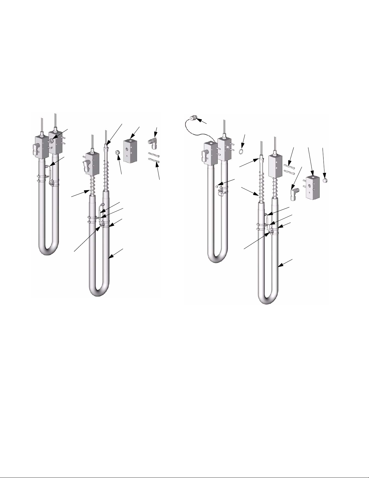
Parts
Fluid Heater
245962 10.2 kW Heater, for A-XP2 Reactors,
and HT-10.2 Heat Packages
* Ref. No. 182 not included with heater.
Order separately, see page 39.
213205207
214
211
202
210
211
182*
203
206
245963 7.65 kW Heater, for HT-15.3 Heat
Packages (2 required)
* Ref. No. 182 not included with heater.
Order separately, see page 39.
214
207
202
212
209
206
211
182*
203
205
213
210
208
201
TI2512b
Ref.
No. Part No. Description Qty
201 15B134 HOUSING 2
202 15B135 MIXER 4
203 118426 CLAMP 8
205 15B132 MANIFOLD 4
206 107218 SCREW 8
207 15B138 HEATER, immersion; 2550 W; 230v 4
208 15B137 SWITCH, overtemperature 4
210 100361 PLUG 4
211 117484 SENSOR, temperature 2
213 117532 ELBOW; 1/2 npt x 1/2 in. (13 mm) OD
tube
214 248187 RUPTURE DISK KIT; see 309969 2
213 117532 ELBOW; 1/2 npt x 1/2 in. (13 mm) OD
tube
214 248187 RUPTURE DISK KIT; see 309969 1
208
201
Ref.
No. Part No. Description Qty
201 15B134 HOUSING 2
202 15B135 MIXER 3
203 118426 CLAMP 6
204 15B133 CROSSOVER 2
205 15B132 MANIFOLD 2
206 107218 SCREW 8
207 15B138 HEATER, immersion;
208 15B137 SWITCH, overtemperature 3
209 100139 PLUG 1
4
210 100361 PLUG 2
211 117484 SENSOR, temperature 1
212 117466 O-RING 1
2
213 117532 ELBOW; 1/2 npt x 1/2 in. (13 mm) OD
214 248187 RUPTURE DISK KIT; see 309969 1
2550 W; 230v
tube
TI2578b
3
2
40 309813H
Page 41
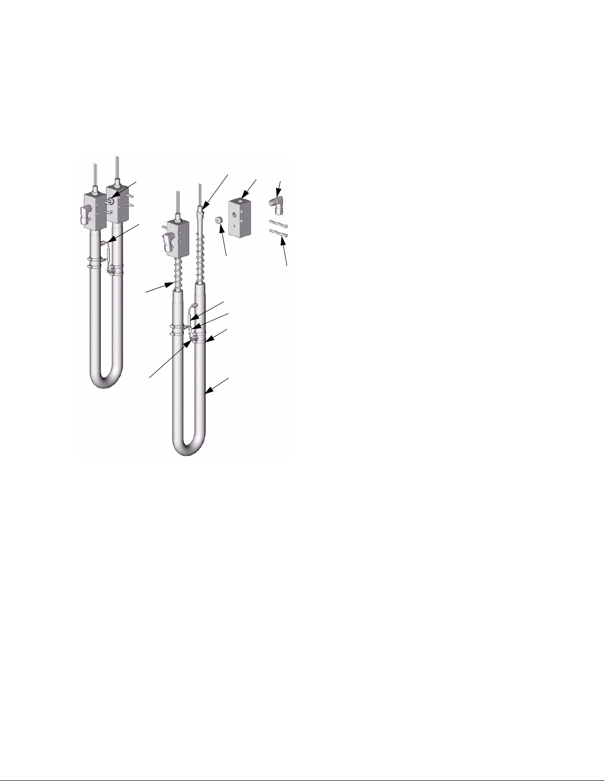
245975 6 kW Heater, for HT-6.0 Heat
*Ref. N
Packages
o. 182 not included with heater.
Order separately, see page 39.
205207
214
211
Parts
213
202
210
211
206
182*
203
208
Ref.
No. Part No. Description Qty
201 15B134 HOUSING 2
202 15B135 MIXER 4
203 118426 CLAMP 8
205 15B132 MANIFOLD 4
206 107218 SCREW 8
207 15B140 HEATER, immersion; 1500 W; 230v 4
208 15B137 SWITCH, overtemperature 4
210 100361 PLUG 2
211 117484 SENSOR, temperature 2
213 117532 ELBOW; 1/2 npt x 1/2 in. (13 mm) OD
tube
214 248187 RUPTURE DISK KIT; see 309969 2
201
TI2512b
4
309813H 41
Page 42
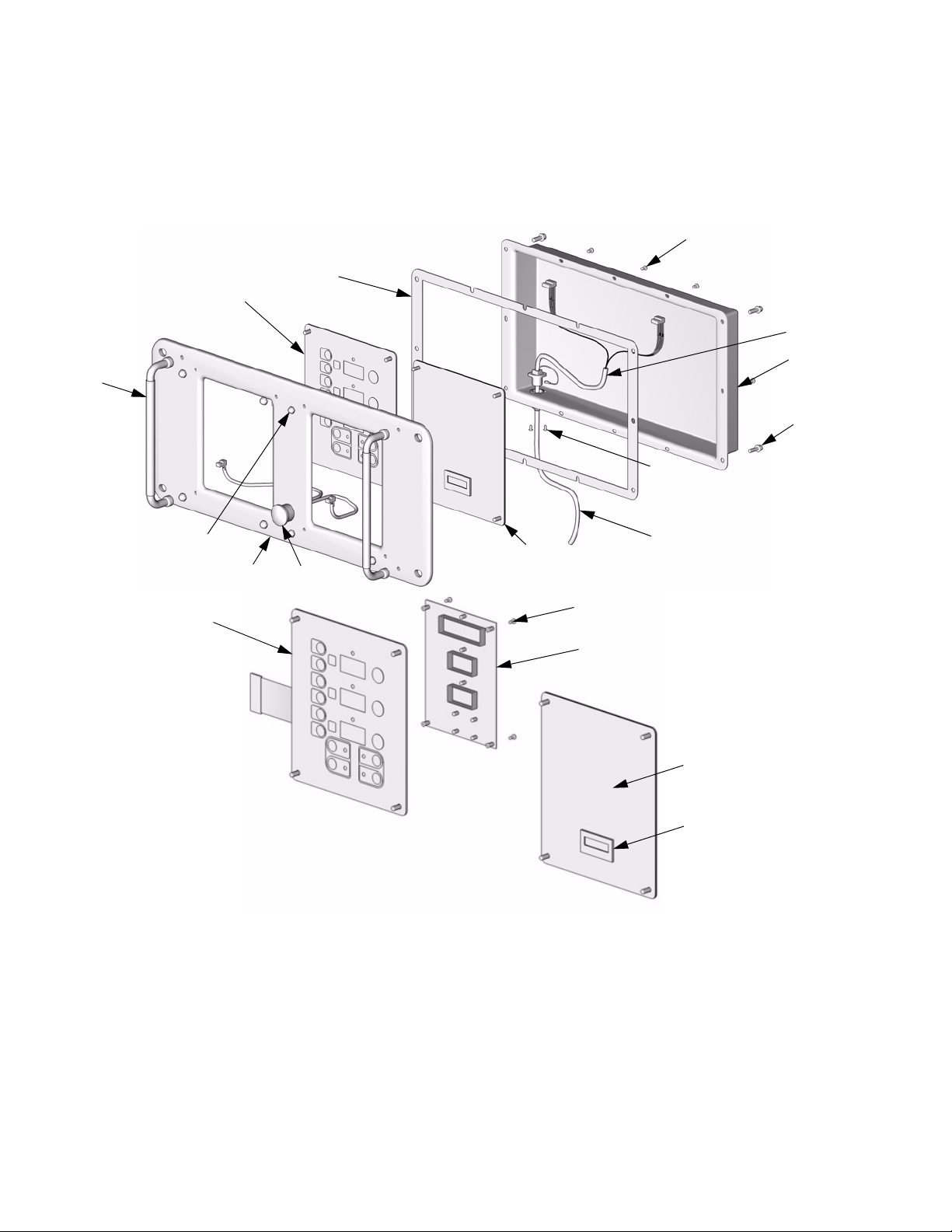
Parts
Display
246043 Display
407
409
403
402
411
404
410
412
408
405
406
402b
Ref.
No. Part No. Description Qty
401 246044 DISPLAY, counter; includes 401a-401b 1
401a 117830 . COUNTER, digital 1
401b 15B365 . LABEL 1
402 245977 DISPLAY, temperature; includes
402a 246130 . BOARD, circuit 1
402b 246479 . SWITCH, membrane 1
402c 112324 . SCREW 4
403 15B293 GASKET 1
404 15B292 COVER 1
405 15B291 PLATE 1
406 246287 HARNESS, wire, red stop button 1
407 117499 HANDLE 2
402a-402c
401
120
402c
402a
401b
401a
Ref.
No. Part No. Description Qty
408 117523 NUT, cap; 10-24 8
409 111008 SCREW, tapping, 6-32; 1/4 in. (6 mm) 8
410 111393 SCREW, machine, pan-hd; M5 x 0.8;
1
411 15B386 CABLE, display 1
412 195853 SCREW, machine; M2.5 x 6 2
414 118115 CONNECTOR, cable; 5-pin; 24 AWG 1
16 mm
TI3703a
TI3702a
4
42 309813H
Page 43
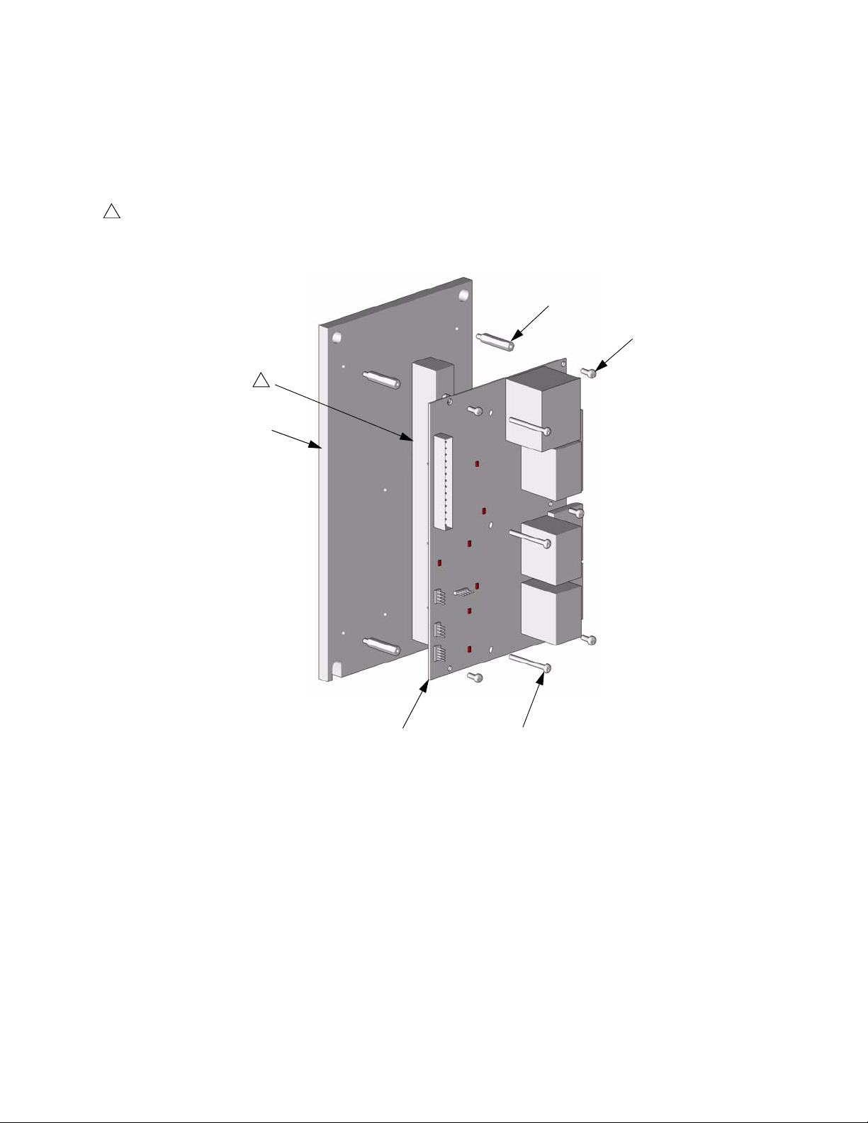
Temperature Control
245979 Temperature Control
1
Apply 110009 thermal heatsink compound to mating surfaces.
1
501
Parts
504
505
TI2575A-1
502 503
Ref.
No. Part No. Description Qty
501 15B779 HEAT SINK 1
502 246194 BOARD, temperature control 1
503 117683 SCREW, 6-32 x 1-1/2 in. (38 mm) 2
504 117526 SPACER 5
505 104590 SCREW, machine; 6-32 x 3/8 in. (10
mm)
309813H 43
5
Page 44
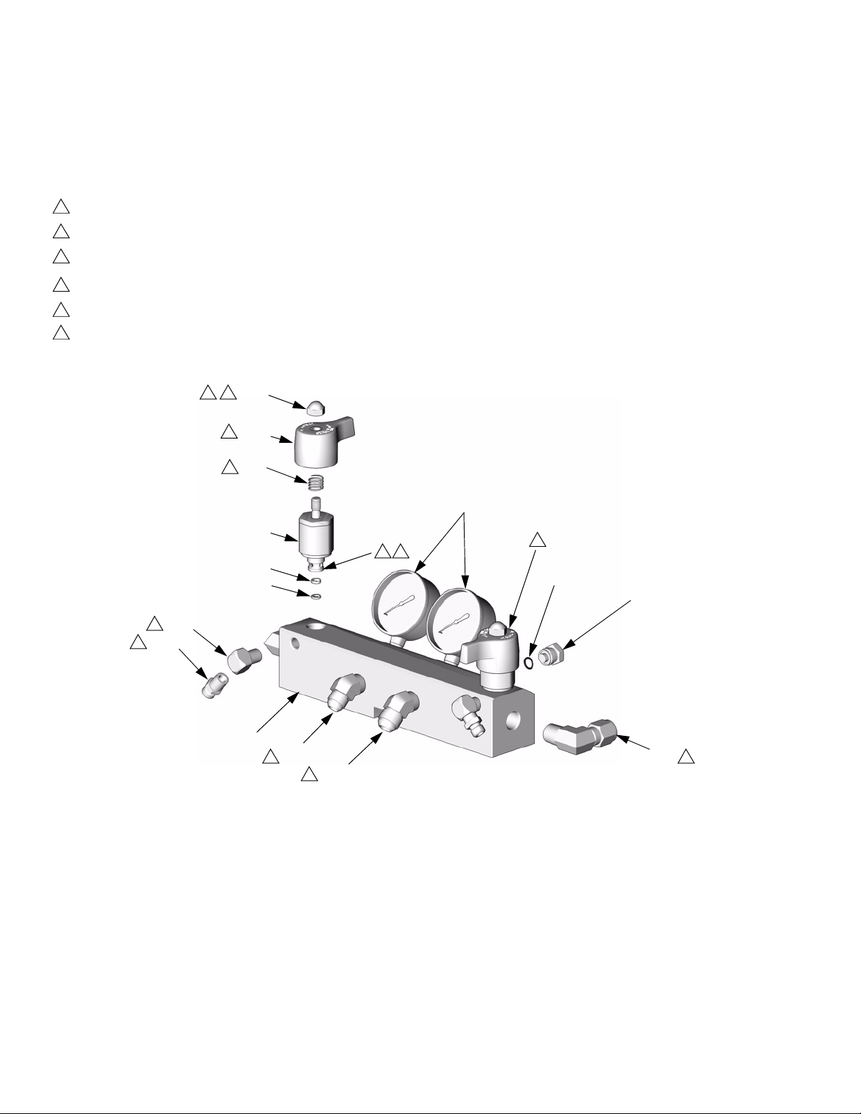
Parts
Fluid Manifold
246042 Fluid Manifold
1
Apply 113500 thread lock (blue).
2
Torque to 355-395 in-lb (40.1-44.6 N•m).
3
Apply PTFE tape or thread sealant to tapered threads.
4
Torque to 175-195 in-lb (19.8-22.0 N•m).
5
Lubricate ends of spring when assembling.
6
Assemble valves (702) and handles (709) with
handles facing away from each other.
*711
1
4
6
709
5
*710
*702
*707
1
*708
718
3
3
705
701
714
3
715
3
Ref.
No. Part No. Description Qty
701 15B332 MANIFOLD; aluminum 1
702* 246161 VALVE, pressure relief/spray 2
704 102814 GAUGE; 5000 psi (35 MPa, 350 bar) 2
705 162453 NIPPLE; 1/4 npt x 1/4 npsm 2
706 198241 PLUG, pressure; 11/16-24 unef 2
707* 193709 SEAT, valve; carbide 2
708* 193710 SEAL, seat; nylon 2
709* 15B287 HANDLE, valve 2
710* 114708 SPRING 2
711* 117623 NUT, cap; 3/8-16 2
704
2
6
720
706
716
3
Ref.
No. Part No. Description Qty
714 117556
715 117557
ELBOW, 45°; #8 JIC x 1/2 npt
ELBOW,
45°; #10 JIC x 1/2 npt
716 117532 ELBOW; 1/2 npt(m) x 1/2 in. (13 mm)
OD tube
718 100840 ELBOW, street; 1/4 npsm x 1/4 npt 2
720 111457 O-RING; PTFE 2
* Included in Repair Kit 245103 (purchase separately).
TI3706b
1
1
2
44 309813H
Page 45
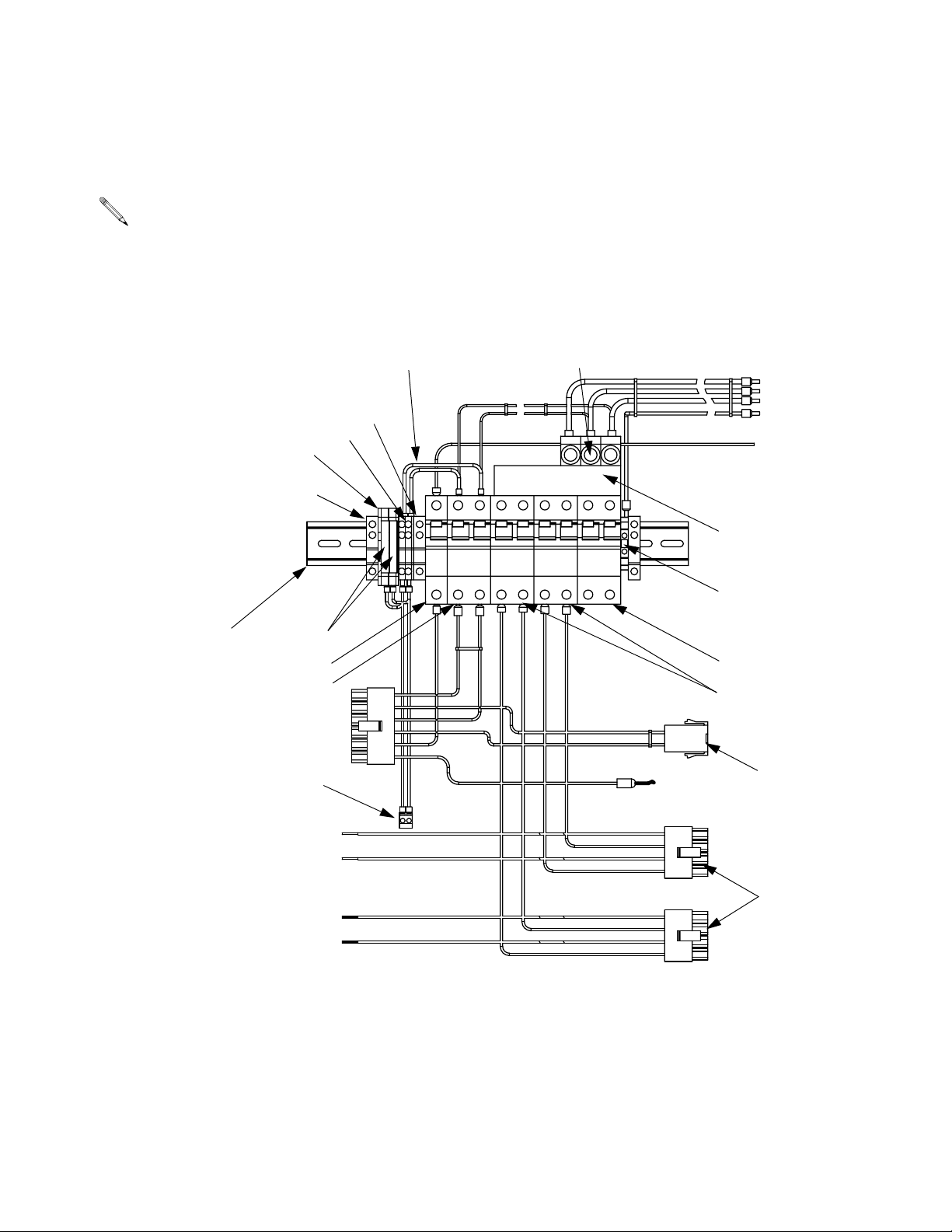
Circuit Breaker Modules
230V, 3 Phase Circuit Breaker Modules
For wiring and cable connections, refer to electrical diagrams supplied. See page 48 for parts list.
Part No. 246087 (A-XP2)
Parts
803,
809
814,
818
802
801
819
806
817
To Temperature Control
Board, J13 (Hose)
810
To Temperature
Control Board, J14
815
808
807
To Hose
L1
L2
L3
GND
From Hose
Transformer
805
813
817
804
To Hose Transformer
811
To Temperature
Control Board, J9 (B)
816
To Temperature
Control Board, J2 (A)
309813H 45
Page 46
Parts
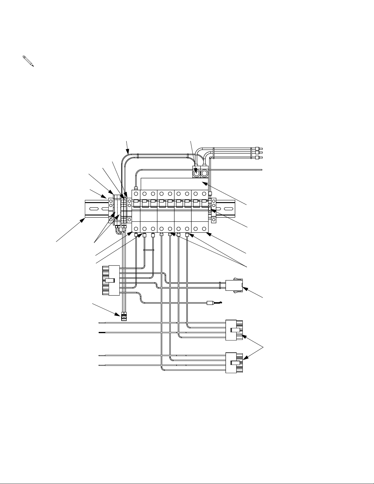
230V, 1 Phase Circuit Breaker Modules
For wiring and cable connections, refer to electrical diagrams supplied. See page 48 for parts list.
Part No. 246090 (A-XP2)
803,
814,
818
802
801
819
806
817
To Temperature Control
Board, J13 (Hose)
810
To Temperature
Control Board, J14
809
815
808
807
To Hose
L1
L2
GND
From Hose
Transformer
805
813
817
804
To Hose Transformer
811
To Temperature
Control Board, J9 (B)
816
To Temperature
Control Board, J2 (A)
46 309813H
Page 47
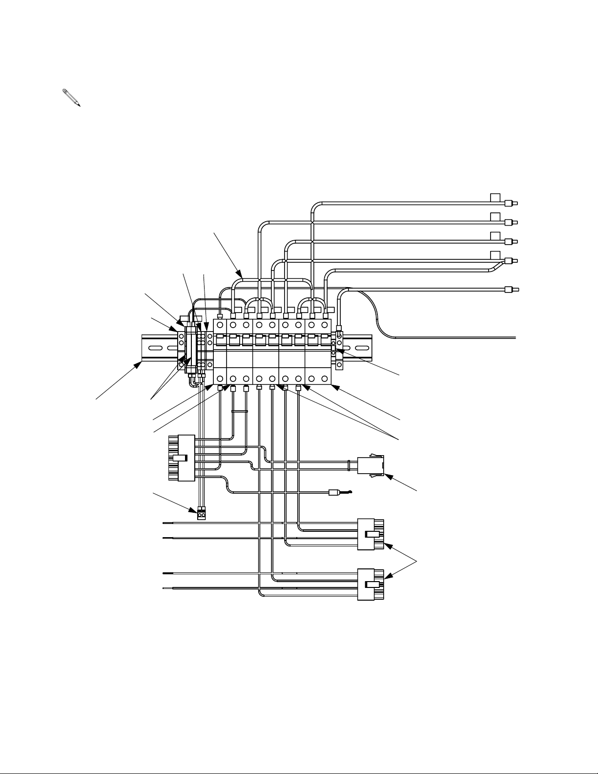
380V, 3 Phase Circuit Breaker Modules
For wiring and cable connections, refer to electrical diagrams supplied. See page 48 for parts list.
Part No. 246096 (A-XP2)
Parts
L1
803,
814,
818
802
801
819
806
817
To Temperature Control
Board, J13 (Hose)
810
To Te m pera tu re
Control Board, J14
B Heaters
815809
808
To Hose
L2
L3
Neutral
GND
From Hose
Transformer
813
817
804
To Hose Transformer
To In-Rush Current Limiter
811
To Temperature
Control Board, J9 (B)
816
A Heaters
309813H 47
To Temperature
Control Board, J2 (A)
Page 48
Parts
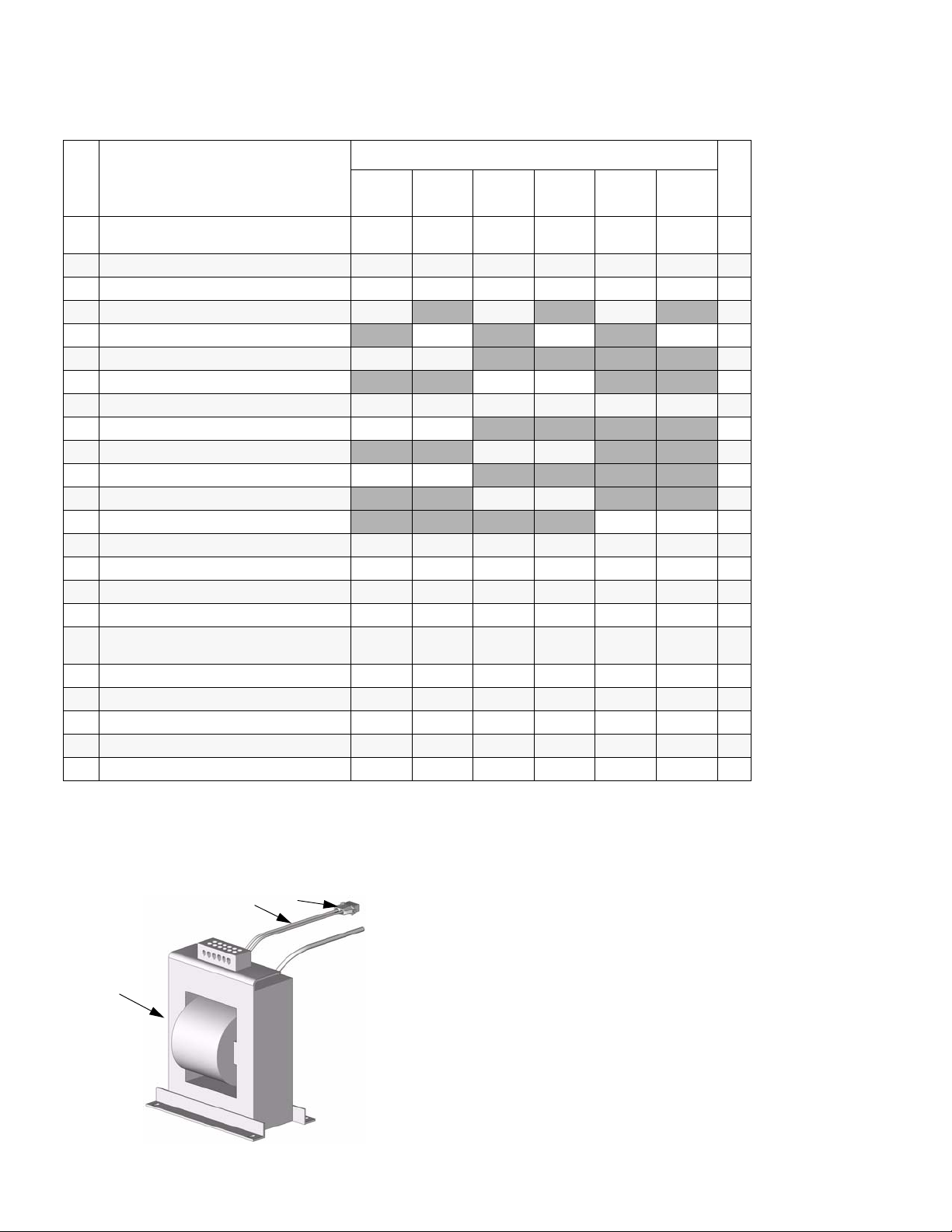
Circuit Breaker Modules Parts List
Ref.
No. Description
246087
230V, 3 θ
246089
230V, 3 θ
Breaker Modules
246090
230V, 1 θ
246092
230V, 1 θ
246096
380V, 3 θ
246098
380V, 3 θ
Qty
801 RAIL, mounting buy
802 CLAMP, end 112446 112446 112446 112446 112446 112446 3
803 TERMINAL, base, fuse plug 117798 117798 117798 117798 117798 117798 2
804 BREAKER, dual; 25A 117591 117591 117591 2
BREAKER, dual; 40A
805 BAR, power buss, 3 phase 117805 117805 1
BAR, power buss, 1 phase
806 BREAKER, single; 50A 117503 117503 117503 117503 117503 117503 1
807 CONNECTOR, power lug 117679 117679
CONNECTOR, power lug 117679 117679 2
808 CABLE, harness; 230V, 3 phase 15B387 15B387
CABLE, harness; 230V, 1 phase 117674 117674 1
CABLE, harness; 380V, 3 phase
809 TERMINAL, block 117796 117796 117796 117796 117796 117796 2
810 CABLE, harness, power temp 15B375 15B375 15B375 15B375 15B375 15B375 1
811 CABLE, hose, heat 15B378 15B378 15B378 15B378 15B378 15B378 1
813 BLOCK, terminal ground 112443 112443 112443 112443 112443 112443 1
814 FUSE, fan; 5 x 20 mm Bussman
GDA-2A or equivalent
815 TERMINAL, end cover 117807 117807 117807 117807 117807 117807 1
816 CABLE, harness, heat A/B 15B376 15B376 15B376 15B376 15B376 15B376 2
817 BREAKER, dual; 20A 117711 117711 117711 117711 117711 117711 2
818 TERMINAL, end cover 117797 117797 117797 117797 117797 117797 1
819 FUSE, plug 117799 117799 117799 117799 117799 117799 2
locally
115216 115216 115216 115216 115216 115216 2
buy
locally
117505 117505 117505 2
buy
locally
117678 117678 1
buy
locally
buy
locally
15B377 15B377 1
buy
locally
1
3
1
Transformer
Part No. 15B352 Transformer
C
H
T
TI3470b
48 309813H
Page 49
Technical Data
Technical Data
Category Data
Maximum Fluid Working
Pressure
Maximum Input Pressure
to Motor
Pressure Ratio
Air Inlet Model A-XP2: 1/2 npsm(f)
Recommended Air Supply
Hose Size
Air Consumption Model A-XP2: 40 scfm at 120 psi (0.82 MPa, 8.2 bar), 1.0 gpm (3.8 lpm)
Recommended Hydraulic
Hose Size
Fluid Inlets Model A-XP2: 3/4 npt(f)
Fluid Outlets Component A (ISO): #8 JIC (3/4-16 unf), with #5 JIC adapter
Fluid Circulation Ports 1/4 npsm(m), with plastic tubing, 250 psi (1.75 MPa, 17.5 bar) maximum
Maximum Fluid Tempera-
ture
Maximum Output (10
weight oil at ambient tem-
perature)
Output per Cycle (A and B) Model A-XP2: 0.0193 gal. (.073 liter)
Line Voltage Requirement 230V 1 phase and 230V 3 phase units: 195-264 Vac, 50/60 Hz
Amperage Requirement See page 3.
Heater Power
(A and B heaters, no hose)
Sound Power, per ISO
9614-2
Sound Pressure, 1 m from
equipment
Weight Model A-XP2: 400 lb (180 kg)
Wetted Parts Aluminum, stainless steel, zinc-plated carbon steel, brass, carbide, chrome, chemically
Model A-XP2: 3000 psi (20.7 MPa, 207 bar)
Model A-XP2: 120 psi (0.82 MPa, 8.2 bar) air
Model A-XP2: 25:1Fluid:Air
Model A-XP2: 1/2 in. (13 mm) ID minimum
Supply Hose: 3/4 in. (19 mm) ID minimum
Return Hose: 1 in. (25 mm) ID minimum
Model HT heat packages: 1/2 npt(f) on heater inlet blocks
Component B (RES): #10 JIC (7/8-14 unf), with #6 JIC adapter
190°F (88°C)
Model A-XP2: 1 gpm (3.8 liter/min) at 60 cycles/min
380V 3 phase units: 338-457 Vac, 50/60 Hz
Model HT-6.0: 6000 Watts
Model A-XP2 and HT-10.2: 10200 Watts
Model HT-15.3: 15300 Watts
Model A-XP2: 94.7 dB(A) at 2000 psi (14 MPa, 140 bar), 0.5 gpm (1.9 lpm), 15 cpm
Model A-XP2: 81 dB(A) at 2000 psi (14 MPa, 140 bar), 0.5 gpm (1.9 lpm), 15 cpm
Models HT-6.0, HT-10.2, and HT-15.3: 333 lb (150 kg)
resistant o-rings, PTFE, ultra-high molecular weight polyethylene
Loctite® is a registered trademark of the Loctite Corporation.
309813H 49
Page 50

Graco Standard Warranty
Graco warrants all equipment referenced in this document which is manufactured by Graco and bearing its name to be free from defects in
material and workmanship on the date of sale to the original purchaser for use. With the exception of any special, extended, or limited warranty
published by Graco, Graco will, for a period of twelve months from the date of sale, repair or replace any part of the equipment determined by
Graco to be defective. This warranty applies only when the equipment is installed, operated and maintained in accordance with Graco’s written
recommendations.
This warranty does not cover, and Graco shall not be liable for general wear and tear, or any malfunction, damage or wear caused by faulty
installation, misapplication, abrasion, corrosion, inadequate or improper maintenance, negligence, accident, tampering, or substitution of
non-Graco component parts. Nor shall Graco be liable for malfunction, damage or wear caused by the incompatibility of Graco equipment with
structures, accessories, equipment or materials not supplied by Graco, or the improper design, manufacture, installation, operation or
maintenance of structures, accessories, equipment or materials not supplied by Graco.
This warranty is conditioned upon the prepaid return of the equipment claimed to be defective to an authorized Graco distributor for verification of
the claimed defect. If the claimed defect is verified, Graco will repair or replace free of charge any defective parts. The equipment will be returned
to the original purchaser transportation prepaid. If inspection of the equipment does not disclose any defect in material or workmanship, repairs will
be made at a reasonable charge, which charges may include the costs of parts, labor, and transportation.
THIS WARRANTY IS EXCLUSIVE, AND IS IN LIEU OF ANY OTHER WARRANTIES, EXPRESS OR IMPLIED, INCLUDING BUT NOT LIMITED
TO WARRANTY OF MERCHANTABILITY OR WARRANTY OF FITNESS FOR A PARTICULAR PURPOSE.
Graco’s sole obligation and buyer’s sole remedy for any breach of warranty shall be as set forth above. The buyer agrees that no other remedy
(including, but not limited to, incidental or consequential damages for lost profits, lost sales, injury to person or property, or any other incidental or
consequential loss) shall be available. Any action for breach of warranty must be brought within two (2) years of the date of sale.
GRACO MAKES NO WARRANTY, AND DISCLAIMS ALL IMPLIED WARRANTIES OF MERCHANTABILITY AND FITNESS FOR A
PARTICULAR PURPOSE, IN CONNECTION WITH ACCESSORIES, EQUIPMENT, MATERIALS OR COMPONENTS SOLD BUT NOT
MANUFACTURED BY GRACO. These items sold, but not manufactured by Graco (such as electric motors, switches, hose, etc.), are subject to
the warranty, if any, of their manufacturer. Graco will provide purchaser with reasonable assistance in making any claim for breach of these
warranties.
In no event will Graco be liable for indirect, incidental, special or consequential damages resulting from Graco supplying equipment hereunder, or
the furnishing, performance, or use of any products or other goods sold hereto, whether due to a breach of contract, breach of warranty, the
negligence of Graco, or otherwise.
FOR GRACO CANADA CUSTOMERS
The Parties acknowledge that they have required that the present document, as well as all documents, notices and legal proceedings entered into,
given or instituted pursuant hereto or relating directly or indirectly hereto, be drawn up in English. Les parties reconnaissent avoir convenu que la
rédaction du présente document sera en Anglais, ainsi que tous documents, avis et procédures judiciaires exécutés, donnés ou intentés, à la suite
de ou en rapport, directement ou indirectement, avec les procédures concernées.
Graco Information
TO PLACE AN ORDER, contact your Graco distributor, or call this number to identify the distributor closest to you:
1-800-328-0211 Toll Free
612-623-6921
612-378-3505 Fax
All written and visual data contained in this document reflects the latest product information available at the time of publication.
Graco reserves the right to make changes at any time without notice.
This manual contains English. MM 309813
Graco Headquarters: Minneapolis
International Offices: Belgium, China, Japan, Korea
GRACO INC. P.O. BOX 1441 MINNEAPOLIS, MN 55440-1441
Copyright 2003, Graco Inc. is registered to I.S. EN ISO 9001
6/2008
 Loading...