

Page 1
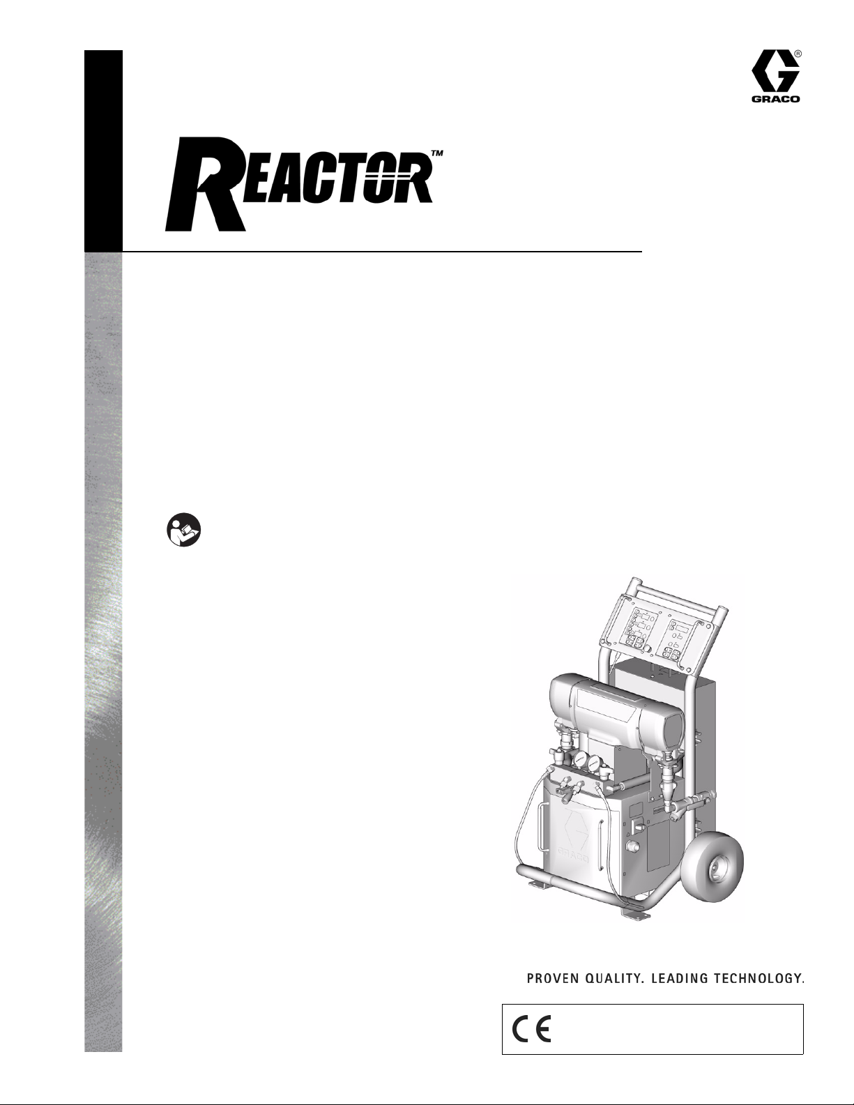
Operation
309551H
Electric, Heated, Plural Component
Proportioner
For spraying polyurethane foam and polyurea coatings.
Not for use in explosive atmospheres.
See Models and Maximum Working Pressures on page 3.
Important Safety Instructions
Read all warnings and instructions in this
manual. Save these instructions.
TI3764a-1
Graco Inc. P.O. Box 1441 Minneapolis, MN 55440-1441
Copyright 2003, Graco Inc. is registered to I.S. EN ISO 9001
Page 2

Contents
Models . . . . . . . . . . . . . . . . . . . . . . . . . . . . . . . . . . . 3
Related Manuals . . . . . . . . . . . . . . . . . . . . . . . . . . . 4
Manual Conventions . . . . . . . . . . . . . . . . . . . . . . . . 4
Warning . . . . . . . . . . . . . . . . . . . . . . . . . . . . . . . . . . . 5
Typical Installation, with circulation . . . . . . . . . . . 7
Typical Installation, without circulation . . . . . . . . 8
Component Identification . . . . . . . . . . . . . . . . . . . . 9
Temperature Controls and Indicators . . . . . . . . . 10
Motor Controls and Indicators . . . . . . . . . . . . . . . 12
Moisture Sensitivity of Isocyanates . . . . . . . . . . . 15
Spray Adjustments . . . . . . . . . . . . . . . . . . . . . . . . 15
Setup . . . . . . . . . . . . . . . . . . . . . . . . . . . . . . . . . . . . 16
Startup . . . . . . . . . . . . . . . . . . . . . . . . . . . . . . . . . . 26
Spraying . . . . . . . . . . . . . . . . . . . . . . . . . . . . . . . . . 29
Shutdown . . . . . . . . . . . . . . . . . . . . . . . . . . . . . . . . 31
Pressure Relief Procedure . . . . . . . . . . . . . . . . . . 32
Fluid Circulation . . . . . . . . . . . . . . . . . . . . . . . . . . . 33
Jog Mode . . . . . . . . . . . . . . . . . . . . . . . . . . . . . . . . 35
Diagnostic Codes . . . . . . . . . . . . . . . . . . . . . . . . . . 36
Maintenance . . . . . . . . . . . . . . . . . . . . . . . . . . . . . . 37
Flushing . . . . . . . . . . . . . . . . . . . . . . . . . . . . . . . . . 37
Accessories . . . . . . . . . . . . . . . . . . . . . . . . . . . . . . 38
Dimensions . . . . . . . . . . . . . . . . . . . . . . . . . . . . . . . 39
Technical Data . . . . . . . . . . . . . . . . . . . . . . . . . . . . 41
Graco Standard Warranty . . . . . . . . . . . . . . . . . . . 42
Graco Information . . . . . . . . . . . . . . . . . . . . . . . . . 42
2 309551H
Page 3

26
Models
E SERIES
26
Flow
Volt age
Part No. Series Model
246025 C E-20 230V (1) 6,000 20 (9) .0104 (.0395) 2000 (14, 140)
246026 B E-30 230V (1) 10,200 30 (13.5) .0272 (0.1034) 2000 (14, 140)
246030 C E-20 380V (3) 6,000 20 (9) .0104 (.0395) 2000 (14, 140)
246031 B E-30 380V (3) 10,200 30 (13.5) .0272 (0.1034) 2000 (14, 140)
246034 C E-20 230V (3) 6,000 20 (9) .0104 (.0395) 2000 (14, 140)
246035 B E-30 230V (3) 10,200 30 (13.5) .0272 (0.1034) 2000 (14, 140)
248657 A E-30 with
15.3kW
248658 A E-30 with
15.3kW
248659 A E-30 with
15.3kW
(phase)
230V (1) 15,300 30 (13.5) .0272 (0.1034) 2000 (14, 140)
230V (3) 15,300 30 (13.5) .0272 (0.1034) 2000 (14, 140)
380V (3) 15,300 30 (13.5) .0272 (0.1034) 2000 (14, 140)
Heater
Watts
lb/min
(kg/min)
Output per
Cycle (A + B)
gal. (liter)
Maximum Fluid
Working Pressure
psi (MPa, bar)
E-XP SERIES
Flow
Volt age
Part No. Series Model
246024 B E-XP1 230V (1) 10,200 1 (3.8) .0104 (.0395) 2500 (17.2, 172)
246028 B E-XP2 230V (1) 15,300 2 (7.6) .0203 (.0771) 3500 (24.1, 241)
246029 B E-XP1 380V (3) 10,200 1 (3.8) .0104 (.0395) 2500 (17.2, 172)
246032 B E-XP2 380V (3) 15,300 2 (7.6) .0203 (.0771) 3500 (24.1, 241)
246033 B E-XP1 230V (3) 10,200 1 (3.8) .0104 (.0395) 2500 (17.2, 172)
246036 B E-XP2 230V (3) 15,300 2 (7.6) .0203 (.0771) 3500 (24.1, 241)
(phase)
Heater
Watts
gpm
(lpm)
Output per
Cycle (A + B)
gal. (liter)
Maximum Fluid
Working Pressure
psi (MPa, bar)
309551H 3
Page 4

Related Manuals
Related Manuals
The following manuals are shipped with the Reactor™
™
Proportioner and the Fusion
these manuals for detailed equipment information.
Order Part No. 15B535 for a compact disk of Reactor
manuals translated in several languages.
Order Part No. 15B381 for a compact disk of Fusion
manual translated in several languages.
Reactor Electric Proportioner
Part No. Description
309574 Reactor Electric Proportioner,
Repair-Parts Manual (English)
309577 Displacement Pump,
Repair-Parts Manual (English)
Reactor Electrical Diagrams (one of the
following is included)
Part No. Description
309726 Electrical Diagrams, E-XP1 and
E-20, 230V, 1 phase
309727 Electrical Diagrams, E-XP2 and
E-30, 230V, 1 phase
309728 Electrical Diagrams, E-XP1 and
E-20, 380V, 3 phase
309729 Electrical Diagrams, E-XP2 and
E-30, 380V, 3 phase
309730 Electrical Diagrams, E-XP1 and
E-20, 230V, 3 phase
309731 Electrical Diagrams, E-XP2 and
E-30, 230V, 3 phase
Reactor Data Reporting Kit
Spray Gun. Refer to
Manual Conventions
Warning
WARNING
A warning alerts you to possible serious injury or
death if you do not follow instructions.
Symbols, such as fluid injection (shown), alert you to a
specific hazard and direct you to read the indicated
hazard warnings on pages 5-6.
Caution
CAUTION
A caution alerts you to possible equipment damage or
destruction if you do not follow instructions.
Note
A note indicates additional helpful information.
Part No. Description
309867 Instruction Manual (English)
Fusion Spray Gun
Part No. Description
309550 Instruction Manual (English)
Heated Hose
Part No. Description
309572 Instruction Manual (English)
4 309551H
Page 5

Warning
WARNING
SKIN INJECTION HAZARD
High-pressure fluid from gun, hose leaks, or ruptured components will pierce skin. This may look like
just a cut, but it is a serious injury that can result in amputation. Get immediate surgical treatment.
• Do not point the gun at anyone or at any part of the body.
• Do not put your hand or fingers over the gun fluid nozzle.
• Do not stop or deflect leaks with your hand, body, glove, or rag.
• Do not “blow back” fluid; this is not an air spray system.
• Follow Pressure Relief Procedure, page 32, when you stop spraying and before cleaning, check-
ing, or servicing equipment.
• Use lowest possible pressure when flushing, priming, or troubleshooting.
• Engage spray gun piston safety lock when not spraying.
• Tighten all fluid connections before operating the equipment.
• Check hoses, tubes, and couplings daily. Replace worn or damaged parts immediately. High pressure hose cannot be recoupled; replace the entire hose.
FIRE, EXPLOSION AND ELECTRIC SHOCK HAZARD
Solvent and fumes in work area can ignite or explode. High voltage components can cause electric
shock. To help prevent fire, explosion, and electric shock:
• Shut off main power switch and wait 5 minutes before opening Reactor cabinet door.
• All electrical wiring must be done by trained and qualified personnel and comply with all local codes.
• Ground equipment and conductive objects. See Ground system, page 24.
• Use equipment only in well ventilated area.
• Eliminate all ignition sources, such as pilot lights, cigarettes and plastic drop cloths (potential static
arc).
• Do not plug or unplug power cords or turn lights on or off when flammable fumes are present.
• Keep the work area free of debris, including solvent, rags, and gasoline.
• Hold gun firmly to side of grounded pail when triggering into pail.
• Use only grounded hoses.
• If there is static sparking or you feel a shock, stop operation immediately. Do not use equipment
until you identify and correct the problem.
• To avoid chemical reaction and explosion, do not use 1,1,1-trichloroethane, methylene chloride,
other halogenated hydrocarbon solvents or fluids containing such solvents in pressurized aluminum
equipment.
309551H 5
Page 6
Warning
WARNING
EQUIPMENT MISUSE HAZARD
Misuse can cause serious injury or death.
• For professional use only.
• Use equipment only for its intended purpose. Call your Graco distributor for information.
• Read manuals, warnings, tags, and labels before operating equipment. Follow instructions.
• Check equipment daily. Repair or replace worn or damaged parts immediately.
• Do not alter or modify equipment. Use only Graco parts and accessories.
• Do not exceed the maximum working pressure or temperature rating of the lowest rated system
component. See Technical Data in all equipment manuals.
• Use fluids and solvents that are compatible with equipment wetted parts. See Technical Data in all
equipment manuals. Read fluid and solvent manufacturer’s warnings.
• Route hoses and cables away from traffic areas, sharp edges, moving parts, and hot surfaces.
• Do not use hoses to pull equipment.
• Comply with all applicable safety regulations.
BURN HAZARD
This equipment is used with heated fluid, which can cause equipment surfaces to become very hot. To
avoid severe burns:
• Do not touch hot fluid or equipment.
• Allow equipment to cool completely before touching it.
• Wear gloves if fluid temperature exceeds 110°F (43°C).
TOXIC FLUID OR FUMES HAZARD
Toxic fluids or fumes can cause serious injury or death if splashed in the eyes or on skin, inhaled, or
swallowed.
• Read Material Safety Data Sheet (MSDS) to know the specific hazards of the fluids you are using.
• Store hazardous fluid in approved containers, and dispose of it according to applicable guidelines.
PERSONAL PROTECTIVE EQUIPMENT
You must wear proper protective equipment when operating, servicing, or when in the operating area of
the equipment to help protect you from serious injury, including eye injury; inhalation of toxic fumes; and
hearing loss. This equipment includes but is not limited to:
• Protective eyewear.
• Gloves, clothing, and respirator as recommended by the fluid and solvent manufacturer.
• Hearing protection.
6 309551H
Page 7
Typical Installation, with circulation
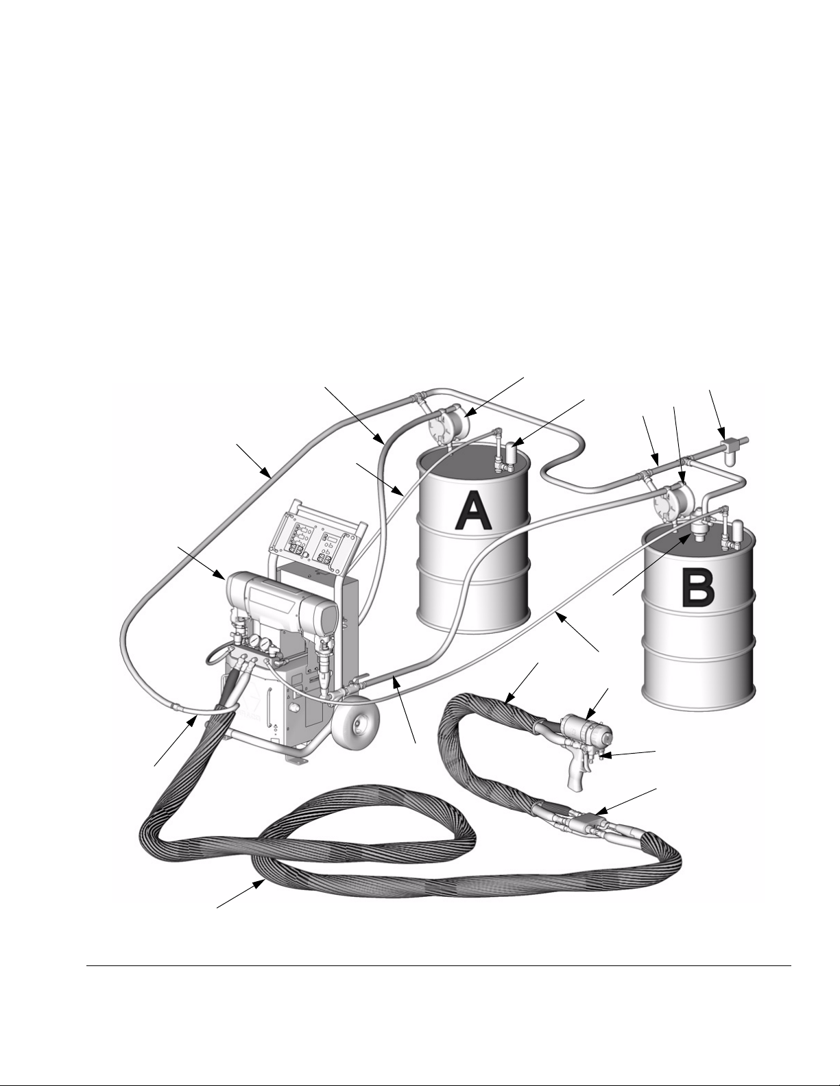
Typical Installation, with circulation
Key for FIG. 1
A Reactor Proportioner
BHeated Hose
C Fluid Temperature Sensor (FTS)
D Heated Whip Hose
E Fusion Spray Gun
F Gun Air Supply Hose
G Air Supply Lines
J Fluid Supply Lines
G
A
K Feed Pumps
L Agitator
M Desiccant Dryer
P Gun Fluid Manifold
Q Air Filter/Separator
R Return Lines
J
R
K
M
G
Q
K
F
B
* Shown exposed for clarity. Wrap with tape during operation.
FIG. 1: Typical Installation, with circulation
L
D
R
E
J
P
C*
TI2765A
309551H 7
Page 8
Typical Installation, without circulation
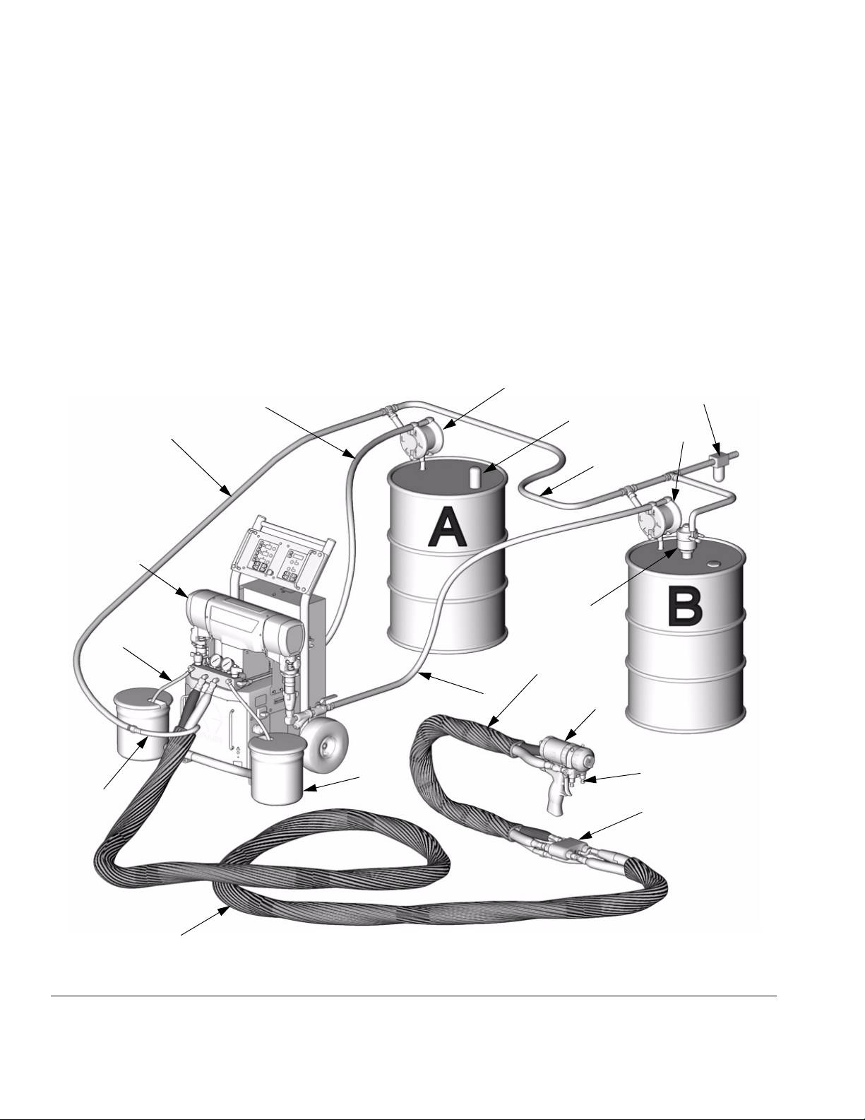
Typical Installation, without circulation
Key for FIG. 2
A Reactor Proportioner
BHeated Hose
C Fluid Temperature Sensor (FTS)
D Heated Whip Hose
E Fusion Spray Gun
F Gun Air Supply Hose
G Air Supply Lines
G
A
H Waste Containers
J Fluid Supply Lines
K Feed Pumps
L Agitator
M Desiccant Dryer
N Bleed Lines
P Gun Fluid Manifold
Q Air Filter/Separator
K
J
Q
M
K
G
N
F
B
* Shown exposed for clarity. Wrap with tape during operation.
FIG. 2: Typical Installation, without circulation
L
D
J
H
E
P
C*
TI2510A
8 309551H
Page 9
Component Identification
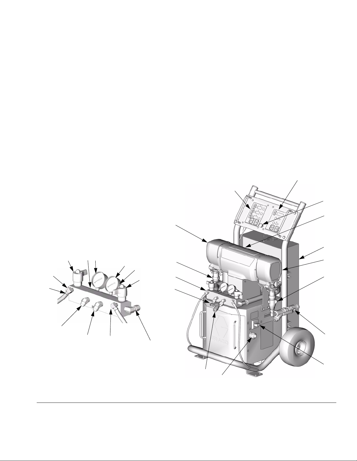
Key for FIG. 3
Component Identification
BA Component A Pressure Relief Outlet
BB Component B Pressure Relief Outlet
FA Component A Fluid Manifold Inlet (behind manifold block)
FB Component B Fluid Manifold Inlet
GA Component A Pressure Gauge
GB Component B Pressure Gauge
HA Component A Hose Connection
HB Component B Hose Connection
PA Component A Pump
PB Component B Pump
SA Component A PRESSURE RELIEF/SPRAY Valve
SB Component B PRESSURE RELIEF/SPRAY Valve
TA Component A Pressure Transducer (behind gauge GA)
TB Component B Pressure Transducer (behind gauge GB)
DG
Detail of Reactor Fluid Manifold
DG Drive Gear Housing
EC Electrical Cord Strain Relief
EM Electric Motor
FH Fluid Heaters (behind shroud)
FM Reactor Fluid Manifold
FV Fluid Inlet Valve (B side shown)
HC Heated Hose Electrical Connector
MC Motor Control Display
MP Main Power Switch
RS Red Stop Button
SC Fluid Temperature Sensor Cable
TC Temperature Control Display
MC
TC
RS
EM
SA
FA
BA
HA
TA
HB
GA
BB
FIG. 3: Component Identification
GB
TB
SB
TI3170
FB
PA
FM
HC
FH
DG
PB
FV
MP
SC
EC
TI3764a-1
309551H 9
Page 10

Temperature Controls and Indicators
Temperature Controls and Indicators
Zone A Arrow Keys
Zone B Arrow Keys
Hose Zone Arrow Keys
Actual Temperature Key
Heater Power Indicators
A
B
Heater Displays
°
F
°
C
Heater A On/Off Key
Heater B On/Off Key
Hose Heater On/Off Key
Temperature Scale Keys
Target Temperature Key
FIG. 4. Temperature Controls and Indicators
10 309551H
Page 11
Temperature Controls and Indicators
Main Power Switch
Located on right side of unit, page 9. Turns Reactor
power ON and OFF . Does not turn
heater zones or pumps on.
Red Stop Button
Located between temperature control panel and motor
control panel, page 9. Press to shut off motor
and heater zones only. Use main power switch to shut
off all power to unit.
Actual Temperature Key/LED
Press to display actual temperature.
Temperature Arrow Keys
Press , then press or to adjust tem-
perature settings in 1 degree increments.
Temperature Displays
Show actual temperature or target temperature of
heater zones, depending on selected mode. Defaults to
actual at startup. Range is 32-190°F (0-88°C) for A and
B, 32-180°F (0-82°C) for hose.
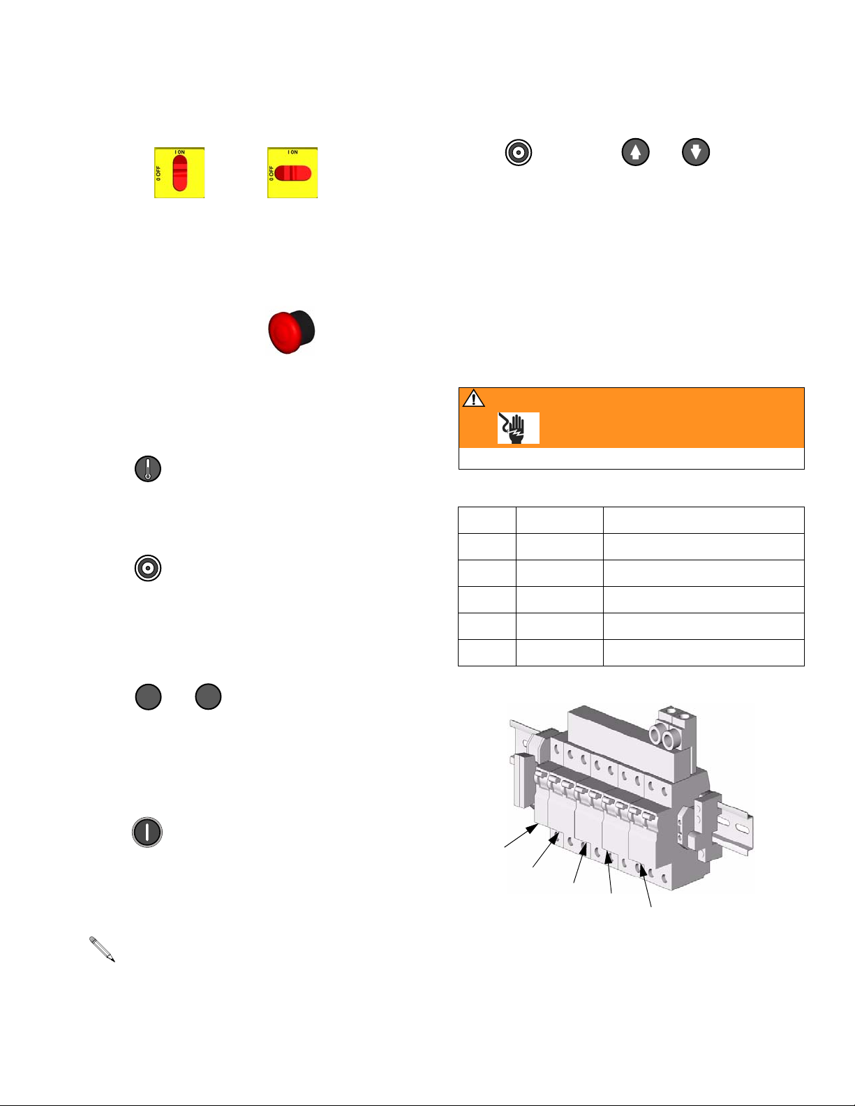
Circuit Breakers
WARNING
Read warnings, page 5.
Located inside Reactor cabinet.
Target Temperature Key/LED
Press to display target temperature.
Temperature Scale
Keys/LEDs
Press or to change temperature scale.
°
F
°
C
Heater Zone On/Off
Keys/LEDs
Press to turn heater zones on and off. Also clears
heater zone diagnostic codes, see page 36.
LEDs are on steady when heater zones are powering
up. Begin flashing as heat reaches targets.
LEDs will also flash if cutback point is reached.
Ref. Size Component
CB1 50 A Hose/Transformer Secondary
CB2 20 A Transformer Primary
CB3 25 or 40 A* Heater A
CB4 25 or 40 A* Heater B
CB5 20 A Motor/Pumps
* Depending on model.
CB1
CB2
CB3
CB4
CB5
For wiring and cabling, see repair manual.
TI2514A
309551H 11
Page 12

Motor Controls and Indicators
Pressure Arrow Keys
Motor ON/OFF Key
ON / OFF
PARK Key
Motor Controls and Indicators
Pressure/Cycle Display
Pressure Key
Cycle Count Key
FIG. 5. Motor Controls and Indicators
PAR K
PSI/BAR Keys
PSI
BAR
12 309551H
Page 13

Motor Controls and Indicators
Motor ON/OFF Key/LED
Press to turn motor ON and OFF. Also clears
some motor control diagnostic codes, see page 36.
PARK Key/LED
Press at end of day to cycle component A pump
to home position, submerging displacement rod. Trigger
gun until pump stops. Once parked, motor will automatically shut off.
PSI/BAR Keys/LEDs
Press or to change pressure scale.
PSI
BAR
Pressure Key/LED
Press to display fluid pressure.
Cycle Count Key/LED
Press to display cycle count.
To clear counter, press and hold for 3 sec.
Pressure Arrow Keys
Press or to adjust fluid pressure when
motor is ON. Setpoint displays for 10 sec.
When motor is OFF, pressing will enter jog mode.
To exit jog mode, press until display shows
dashes or current pressure.
Pressure/Cycle Display
Shows fluid pressure or cycle count, depending on
mode selected.
If pressures are imbalanced, display shows higher
of two pressures.
Displays J 1 through J 10 when in jog mode, page 35.
309551H 13
Page 14

Motor Controls and Indicators
14 309551H
Page 15

Moisture Sensitivity of Isocyanates
Moisture Sensitivity of Isocyanates
Isocyanates (ISO) are catalysts used in two component
foam and polyurea coatings. ISO will react with moisture
(such as humidity) to form small, hard, abrasive crystals,
which become suspended in the fluid. Eventually a film
will form on the surface and the ISO will begin to gel,
increasing in viscosity. If used, this partially cured ISO
will reduce performance and the life of all wetted parts.
The amount of film formation and rate of crystallization varies depending on the blend of ISO.
To prevent exposing ISO to moisture:
• Always use a sealed container with a desiccant
dryer in the vent, or a “nitrogen blanket.” Never store
ISO in an open container.
Spray Adjustments
Flow rate, atomization, and amount of overspray are
affected by four variables.
• Keep the wet-cup of the pump filled with Graco ISO
pump oil, Part No. 217374. The lubricant creates a
barrier between the ISO and the atmosphere.
• Use moisture resistant hoses. The component A
(ISO) hose must be constructed of polyethylene
(PE), PTFE, polyolefin, or moisture-proof rubber
compounds.
• Never use reclaimed solvents, which may contain
moisture. Always keep solvent containers closed
when not in use.
• Always park component A pump when you shutdown, see page 13.
• Mix chamber size. Choice of mix chamber is based
on desired flow rate and fluid viscosity.
• Fluid pressure setting. Too little pressure results in
an uneven pattern, coarse droplet size, low flow,
and poor mixing. Too much pressure results in
excessive overspray, high flow rates, difficult control,
and excessive wear.
• Fluid temperature. Similar effects to fluid pressure
setting. The A and B temperatures can be offset to
help balance the fluid pressure.
• Cleanoff air adjustment. Too little cleanoff air
results in droplets building up on the front of the
nozzle, and no pattern containment to control overspray. Too much cleanoff air results in air-assisted
atomization and excessive overspray.
309551H 15
Page 16

Setup
Setup
1. Locate Reactor
a. Locate Reactor on a level surface.
b. Do not expose Reactor to rain.
c. To mount on a truck bed, secure rear
axle with 15B805 Mobile Mounting
Bracket (MB), available separately. Bolt
bracket and mounting feet (MF) of
Reactor to truck bed.
MB MF
TI3548a
2. Electrical requirements
See TABLE 1.
WARNING
Installing this equipment requires access to parts
which may cause electric shock or other serious injury
if work is not performed properly. Have a qualified
electrician connect power and ground to main power
switch terminals, see page 17. Be sure your installation complies with all National, State and Local safety
and fire codes.
Table 1: Electrical Requirements
(kW/Full Load Amps)
E SERIES
Full
Load
Volt age
Part No. Model
246025 E-20 230V (1) 48 10,200
246026 E-30 230V (1) 78 17,900
246030 E-20 380V (3) 24 10,200
246031 E-30 380V (3) 34 17,900
246034 E-20 230V (3) 32 10,200
246035 E-30 230V (3) 50 17,900
248657 E-30† 230V (1) 100 23,000
248658 E-30† 230V (3) 62 23,000
248659 E-30† 380V (3) 35 23,000
246024 E-XP1 230V (1) 69 15,800
246028 E-XP2 230V (1) 100 23,000
246029 E-XP1 380V (3) 24 15,800
246032 E-XP2 380V (3) 35 23,000
246033 E-XP1 230V (3) 43 15,800
246036 E-XP2 230V (3) 62 23,000
* Full load amps with all devices operating at maximum
capabilities. Fuse requirements at various flow rates and
mix chamber sizes may be less.
** E-20 and E-XP1 with 210 ft (64.1 m) hose; E-30 and
E-XP2 with 310 ft (94.6 m) hose.
† E-30 with 15.3 kW of heat.
(phase)
E-XP SERIES
Peak
Amps*
System
Watts**
16 309551H
Page 17

Setup
3. Connect electrical cord
Power cord is not supplied. See TABLE 2.
Table 2: Power Cord Requirements
Cord Specification
Part No. Model
246024 E-XP1 6 (13.3), 2 wire + ground
246025 E-20 8 (8.4), 2 wire + ground
246026 E-30 6 (13.3), 2 wire + ground
246028 E-XP2 4 (21.2), 2 wire + ground
246029 E-XP1 10 (5.3), 4 wire + ground
246030 E-20 10 (5.3), 4 wire + ground
246031 E-30 10 (5.3), 4 wire + ground
246032 E-XP2 10 (5.3), 4 wire + ground
246033 E-XP1 8 (8.4), 3 wire + ground
246034 E-20 10 (5.3), 3 wire + ground
246035 E-30 8 (8.4), 3 wire + ground
246036 E-XP2 6 (13.3), 3 wire + ground
248657 E-30 4 (21.2), 2 wire + ground
248658 E-30 6 (13.3), 3 wire + ground
248659 E-30 10 (5.3) 4 wire + ground
AWG (mm
2
)
WARNING
Read warnings, page 5.
a. 230V, 1 phase: Using 5/32 or 4 mm hex
allen wrench, connect two power leads
to L1 and L2. Connect green to ground
(GND).
GND
L1
L2
TI2515B
309551H 17
Page 18

b. 230V, 3 phase: Using 5/32 or 4 mm hex
allen wrench, connect three power
leads to L1, L2, and L3. Connect green
to ground (GND).
GND
L1
L2
L3
TI3248B
Setup
c. 380V, 3 phase: Using 5/32 or 4 mm hex
allen wrench, connect three power
leads to L1, L2, and L3. Connect neutral
to N. Connect green to ground (GND).
GND
L1
L3
L2
N
TI2725A
18 309551H
Page 19

Setup
4. Connect feed pumps
a. Install feed pumps (K) in component A
and B supply drums. See F
F
IG. 2, pages 7 and 8.
IG. 1 and
b. Seal component A drum and use desic-
cant dryer (M) in vent.
c. Install agitator (L) in component B drum,
if necessary.
d. Connect supply hoses (J) from feed
pumps to Reactor fluid inlet valves (FV).
FV
5. Connect pressure relief
lines
WARNING
Do not install shutoffs downstream of the PRESSURE
RELIEF/SPRAY valve outlets (BA, BB). The valves
function as overpressure relief valves when set to
SPRAY. Lines must be open so valves can automatically relieve pressure when machine is operating.
If circulating fluid back to the supply drums, use high
pressure hose rated to withstand the maximum working pressure of this equipment.
a. Recommended: Connect high pres-
sure hose (R) to relief fittings (BA, BB)
of both PRESSURE RELIEF/SPRAY
valves, Route hose back to component
A and B drums. See F
IG. 1, page 7.
J
TI2501A
Supply hoses from feed pumps should be 3/4 in.
(19 mm) ID.
BA BB
TI3171a
b. Alternately: Secure supplied bleed
tubes (N) in grounded, sealed waste
containers (H). See F
IG. 2, page 8.
309551H 19
Page 20

Setup
6. Install Fluid Temperature
Sensor (FTS)
The Fluid Temperature Sensor (FTS) is supplied.
Install FTS between main hose and whip hose.
CAUTION
To prevent damage to probe, do not kink or excessively bend whip hose. Do not coil hose tighter than
the minimum bend radius of 3 ft (0.9 m). Do not subject hose to excessive weight, impact, or other abuse.
a. Carefully extend FTS probe (S). Do not
bend or kink probe. Insert in component
A (ISO) side of main hose (B).
b. Connect FTS (C) to whip hose (D).
c. Connect whip hose ground wire (U) to
ground screw on underside of FTS.
d. Connect main hose (B) to FTS (C).
e. Connect electrical connectors (V).
Secure connections with plastic ties
(W).
f. Connect air hose (F) to whip air hose
(X).
g. Connect main hose cable (Y) to FTS.
Slide insulator sleeves over connection.
Leave slack (Z) in cables as stress
relief, to prevent cable failure.
V
U
C
Y
Z
V
B
S
F
W
D
X
TI9582a
F
IG. 6. Install Fluid Temperature Sensor (FTS)
20 309551H
Page 21

Setup
7. Connect heated hose
See 309572 for detailed instructions for Graco
heated hoses.
CAUTION
The fluid temperature sensor (FTS) and whip hose
must be used with heated hose, see page 20. Hose
length, including whip hose, must be 60 ft (18.3 m)
minimum.
a. Turn main power OFF .
b. Assemble heated hose sections, FTS,
and whip hose.
c. Connect A and B hoses to A and B out-
lets on Reactor fluid manifold (FM).
Hoses are color coded: red for component A (ISO), blue for component B
(RES). Fittings are sized to prevent connection errors.
FM
N
A
P
B
TI2726A
Manifold hose adapters (N, P) allow use of 1/4 in.
and 3/8 in. ID fluid hoses. To use 1/2 in. (13 mm)
ID fluid hoses, remove adapters from fluid manifold and install as needed to connect whip hose.
d. Connect cables (Y). Connect electrical
connectors (V). Secure with plastic ties.
Be sure cables have slack when hose
bends. Wrap cable and electrical connections with electrical tape.
Y
V
TI2727A
309551H 21
Page 22

Setup
8. Close gun fluid manifold
valves A and B
TI2411A
9. Connect whip hose to
gun fluid manifold
Do not connect manifold to gun.
TI2417A
10. Pressure check hose
See hose manual. Pressure check for leaks. If
no leaks, wrap hose and electrical connections
to protect from damage.
22 309551H
Page 23

11. Set transformer wire
taps
WARNING
Read warnings, page 5.
Turn main power switch OFF . Transformer tap
wire connections vary depending on length of heated
hose. See F
tions are correct.
IG. 7 and FIG. 8. Verify that tap wire connec-
100 ft 150 ft 200 ft
50 ft
Setup
250 ft
300 ft
50 ft
.
Hose Length* ft (m) Tap Terminal
60-85 (18.3-25.9) 50
110-135 (33.5-41.2) 100
100 ft 150 ft
200 ft
Label (ft)
TI3469a
TI3470a
Hose Length* ft (m) Tap Terminal
Label (ft)
60-85 (18.3-25.9) 50
110-135 (33.5-41.2) 100
160-185 (48.8-56.4) 150
210-235 (64.1-71.7) 200
260-285 (79.3-86.9) 250
310 (94.6) 300
* Length includes heated fluid hose and whip hose.
FIG. 8: Model E-30 and E-XP2 Transformer Wire Taps
160-185 (48.8-56.4) 150
210-235 (64.1-71.7) 200
* Length includes heated fluid hose and whip hose.
F
IG. 7: Model E-20 and E-XP1 Transformer Wire Taps
309551H 23
Page 24

Setup
12. Ground system
WARNING
Read warnings, page 5.
a. Reactor: is grounded through power
cord. See page 17.
b. Spray gun: connect whip hose ground
wire to FTS, page 20. Do not disconnect
wire or spray without whip hose.
c. Fluid supply containers: follow your local
code.
d. Object being sprayed: follow your local
code.
e. Solvent pails used when flushing: follow
your local code. Use only metal pails,
which are conductive, placed on a
grounded surface. Do not place pail on
a nonconductive surface, such as paper
or cardboard, which interrupts grounding continuity.
f. To maintain grounding continuity when
flushing or relieving pressure, hold a
metal part of spray gun firmly to the side
of a grounded metal pail, then trigger
gun.
24 309551H
Page 25

Setup
13. Supply wet-cups with
Throat Seal Liquid
WARNING
Pump rod and connecting rod move during operation.
Moving parts can cause serious injury such as pinching or amputation. Keep hands and fingers away from
wet-cup during operation. Turn main power OFF
before filling wet cup.
a. Component A (ISO) Pump: Keep res-
ervoir (R) filled with Graco Throat Seal
Liquid (TSL), Part No. 206995. Wet-cup
piston circulates TSL through wet-cup,
to carry away isocyanate film on displacement rod.
b. Component B (Resin) Pump: Check
felt washers in packing nut/wet-cup (R)
daily. Keep saturated with Graco Throat
Seal Liquid (TSL), Part No. 206995, to
prevent material from hardening on displacement rod. Replace felt washers
when worn or contaminated with hardened material.
R
TI3765a-1
R
TI3765a-2
309551H 25
Page 26

Startup
Startup
WARNING
Do not operate Reactor without all covers and shrouds
in place.
1. Fluid Temperature
Sensor (FTS) Calibration
Calibrate the FTS ONLY at initial startup (the first
time the unit is operated) and any time the hose
length changes.
a. Before turning on the unit, ensure all
hoses and cables are properly connected. To ensure that the FTS in the
hose is at the same temperature as the
heaters, keep heat off and store the
hose FTS near the machine for several
minutes.
c. Turn both PRESSURE RELIEF/SPRAY
valves (SA, SB) to SPRAY.
SA
SB
TI2482A
d. Open fluid inlet valves (FV).
FV
TI2501A
b. While holding down the temperature
unit button (Fahrenheit - “F” or Celsius “C”) turn the Reactor main power ON.
c. Hold the temperature unit button until
temperature is shown on the display.
The fluid temperature sensor is now correctly calibrated.
2. Load fluid with feed
pumps
The Reactor is tested with oil at the factory. Flush
out the oil with a compatible solvent before spraying. See page 37.
a. Check that Setup steps 1-13 are com-
plete, pages 16-25.
e. Start feed pumps.
WARNING
Always provide two grounded waste containers to
keep component A and component B fluids separate.
f. Hold gun fluid manifold over two
grounded waste containers. Open fluid
valves A and B until clean, air-free fluid
comes from valves. Close valves.
b. Turn on component B agitator, if used.
26 309551H
TI2484A
Page 27

Startup
3. Set temperatures
WARNING
This equipment is used with heated fluid, which can
cause equipment surfaces to become very hot. To
avoid severe burns:
• Do not touch hot fluid or equipment.
• Allow equipment to cool completely before touching it.
• Wear gloves if fluid temperature exceeds 110°F
(43°C).
a. Turn main power ON .
b. Press or to change tem-
perature scale.
°
F
°
C
For zone only, if FTS is disconnected at
startup, display will show hose current (0A). See
step h, page 28.
e. Press to display actual tempera-
tures.
WARNING
Read warnings, page 5. Do not turn on hose heat
without fluid in hoses.
f. Turn on heat zone by pressing
. Preheat hose (15-60 min). Indi-
cator will flash very slowly when fluid
reaches target temperature. Display
shows actual fluid temperature in hose
near FTS.
c. Press .
d. To set heat zone target tempera-
ture, press or until display
shows desired temperature. Repeat for
A
and zones.
B
WARNING
Read warnings, page 5. Thermal expansion can
cause overpressurization, resulting in equipment rupture and serious injury, including fluid injection. Do not
pressurize system when preheating hose.
g. Turn on and heat zones
by pressing for each zone.
A
B
309551H 27
Page 28

Startup
h. Manual current control mode only:
WARNING
Read warnings, page 5. When in manual current control mode, monitor hose temperature with thermometer. Install per instructions below. Thermometer
reading must not exceed 160°F (71°C).
If FTS is disconnected or display shows
diagnostic code E04, turn main power
switch OFF then ON
to clear diagnostic code and enter man-
ual current control mode. display
will show current to hose. Current is not
limited by target temperature.
4. Set pressure
a. Press .
b. Press motor . Motor and pumps
start. Display shows system pressure.
Motor runs until setpoint reached.
c. Press or until display
shows desired fluid pressure. Display
will show setpoint for 10 sec, then
change to actual pressure.
If display pressure is greater than setpoint pressure, trigger gun to reduce pressure.
To prevent overheating, install hose
thermometer close to gun end, within
operator view. Insert thermometer
through foam cover of A component
hose so stem is next to inner tube.
Thermometer reading will be about
20°F less than actual fluid temperature.
If thermometer reading exceeds 160°F
(71°C), reduce current with key.
If display shows J xx, unit is in jog mode. To exit
jog mode, see page 35.
d. To display cycle count, press .
To clear counter, press and hold for 3 sec.
e. Press or to change pres-
sure scale.
PSI
BAR
28 309551H
Page 29

Spraying
Spraying
1. Engage gun piston safety lock.
2. Close gun fluid manifold valves A and B.
TI2409A
TI2728A
4. Set PRESSURE RELIEF/SPRAY valves (SA,
SB) to SPRAY.
SA
SB
TI2482A
5. Check that heat zones are on and temperatures
are on target, page 27.
6. Press motor to start motor.
3. Attach gun fluid manifold. Connect gun air line.
Open air line valve.
TI2543A
309551H 29
Page 30

Spraying
7. Check fluid pressure display and adjust as nec-
essary, page 28.
8. Check fluid pressure gauges (GA, GB) to ensure
proper pressure balance. If imbalanced, see
repair manual.
GA
GB
TI2482A
9. Open gun fluid manifold valves A and B.
10. Disengage gun piston safety lock.
TI2410A
11. Test spray onto cardboard for several seconds,
to allow Reactor to adjust motor speed as
required for gun mix chamber nozzle. Adjust
pressure and temperature to get desired results.
12. Equipment is ready to spray.
TI2414A
30 309551H
Page 31

Shutdown
Shutdown
1. Shut off , , and heat zones.
A
B
2. Park component A pump.
a. Press .
b. Trigger gun until pump A stops. After
fluid pressure drops below 700 psi (4.9
MPa, 49 bar), motor will run until component A pump is at bottom of its stroke,
then shut off.
c. Fill wet-cups, page 25.
3. Turn main power OFF .
4. Relieve pressure, page 32.
309551H 31
Page 32

Pressure Relief Procedure
Pressure Relief Procedure
1. Relieve pressure in gun and perform gun shut-
down procedure. See gun manual.
2. Close gun fluid manifold valves A and B.
TI2421A
3. Shut off feed pumps and agitator, if used.
4. Turn PRESSURE RELIEF/SPRAY valves (SA,
SB) to PRESSURE RELIEF. Route fluid to waste
containers or supply tanks. Ensure gauges drop
to 0.
5. Engage gun piston safety lock.
TI2409A
6. Disconnect gun air line and remove gun fluid
manifold.
TI2554A
SA
SB
TI2481A
32 309551H
Page 33

Fluid Circulation
B
B
Circulation Through Reactor
WARNING
Fluid Circulation
4. Turn main power ON .
Read warnings, page 5. Do not circulate fluid containing a blowing agent without consulting with your material supplier regarding fluid temperature limits.
To circulate through gun manifold and preheat hose, see
page 34.
1. Load fluid with feed pumps, page 26.
WARNING
Do not install shutoffs downstream of the PRESSURE
RELIEF/SPRAY valve outlets (BA, BB). The valves
function as overpressure relief valves when set to
SPRAY. Lines must be open so valves can automatically relieve pressure when machine is operating.
5. Set temperature targets, see page 27. Turn on
and heat zones by pressing
A
. Do not turn on heat zone unless
hoses are already loaded with fluid.
6. Press to display actual temperatures.
7. Circulate fluid in jog mode (see page 35) until
and temperatures reach targets.
A
8. Turn on heat zone by pressing .
2. Route circulation lines back to respective com-
ponent A or B supply drum. Use hoses rated at
the maximum working pressure of this equipment. See F
IG. 1, page 7.
9. Set PRESSURE RELIEF/SPRAY valves (SA,
SB) to SPRAY.
SB
3. Set PRESSURE RELIEF/SPRAY valves (SA,
SB) to PRESSURE RELIEF.
SA
SB
BA
BB
309551H 33
TI2481A
SA
TI2482A
Page 34

Fluid Circulation
Circulation Through Gun
Manifold
WARNING
Read warnings, page 5. Do not circulate fluid containing a blowing agent without consulting with your material supplier regarding fluid temperature limits.
Circulating fluid through the gun manifold allows rapid
preheating of hose.
1. Install gun fluid manifold (P) on Part No. 246362
accessory circulation kit (W).
2. Connect high pressure circulation lines (R) to
circulation manifold. Route circulation lines back
to respective component A or B supply drum.
Use hoses rated at the maximum working pressure of this equipment.
3. Follow Load fluid with feed pumps, page 26.
4. Turn ma in power ON .
5. Set temperature targets, see page 27. Turn on
, , and heat zones by press-
A
ing .
B
W
P
R
6. Press to display actual temperatures.
TI2767A
7. Circulate fluid only in jog mode (see page 35)
until temperatures reach targets.
34 309551H
Page 35

Jog Mode
Jog Mode
Jog mode has two purposes:
• It can speed fluid heating during circulation
• It can make pump repair/replacement easier. See
repair manual.
1. Turn main power ON .
2. Check that motor is OFF (LED is off; dis-
play may show dashes or pressure).
3. Press to select J 1 (jog speed 1).
4. Press motor to start motor.
5. Press or to change jog speed
(J 1 through J 10).
Jog speeds correlate to 3-30% of motor power,
but will not operate over 700 psi (4.9 MPa, 49 bar)
for either A or B.
6. To exit jog mode, press until display
shows dashes or current pressure.
309551H 35
Page 36

Diagnostic Codes
Temperature Control Diagnostic Codes
Temperature control diagnostic codes E01 through E05
appear on temperature display.
These alarms turn off heat. Turn main power OFF
then ON to clear.
See repair manual for corrective action.
Code
No.
01 High fluid temperature Individual
02 High hose current Hose only
03 No hose current with hose heater on Hose only
04 FTS or thermocouple not connected Individual
05 Board overtemperature All
For hose zone only, if FTS is disconnected at startup, display will show hose current 0A.
Diagnostic Codes
Code Name Alarm Zone
Motor Control Diagnostic Codes
Motor control diagnostic codes E21 through E29 appear
on pressure display.
There are two types of motor control codes: alarms and
warnings. Alarms take priority over warnings.
See repair manual for corrective action.
Alarms
Alarms turn off Reactor. Turn main power OFF
then ON to clear.
Alarms can also be cleared, except for code 23,
by pressing .
Warnings
Reactor will continue to run. Press to clear. A
warning will not recur for a predetermined amount of
time (varies for different warnings), or until main power
is turned OFF then ON .
Code
No.
21 No transducer (component A) Alarm
22 No transducer (component B) Alarm
23 High pressure Alarm
24 Pressure imbalance Selectable; see
25 High line voltage Alarm
26 Low line voltage Alarm
27 High motor temperature Alarm
28 High current Alarm
29 Brush wear Warning
Code Name Alarm or Warning
repair manual
36 309551H
Page 37

Maintenance
Maintenance
• Check wet-cup TSL supply daily, page 25.
• Do not overtighten packing nut/wet-cup. Throat
u-cup is not adjustable.
• Keep component A from exposure to moisture in
atmosphere, to prevent crystallization.
• Remove plug (S) and clean fluid inlet screens as
needed.
Flushing
WARNING
Read warnings, page 5. Flush equipment only in a
well-ventilated area. Do not spray flammable fluids. Do
not turn on heaters while flushing with flammable solvents.
• Flush out old fluid with new fluid, or flush out old
fluid with a compatible solvent before introducing
new fluid.
• Use the lowest possible pressure when flushing.
• All fluid components are compatible with common
solvents. Use only moisture-free solvents.
• To flush feed hoses, pumps, and heaters separately
from heated hoses, set PRESSURE
RELIEF/SPRAY valves (SA, SB) to PRESSURE
RELIEF. Flush through bleed lines (N).
S
• Clean gun mix chamber ports regularly. See gun
manual.
• Clean gun check valve screens regularly. See gun
manual.
• Use compressed air to prevent dust buildup on control boards, fan, and motor (under shield).
TI2501A
SA
SB
N
N
• To flush entire system, circulate through gun fluid
manifold (with manifold removed from gun).
• Always leave some type of fluid in system. Do not
use water.
TI2481A
309551H 37
Page 38

Accessories
Accessories
Feed Pump Kits
Pumps, hoses, and mounting hardware to supply fluids
to Reactor. Includes 246483 Air Supply Kit. See
309815.
246483 Air Supply Kit
Hoses and fittings to supply air to feed pumps, agitator,
and gun air hose. Included in feed pump kits. See
309827.
246978 Circulation Kit
Return hoses and fittings to make circulation system.
Includes two 246477 Return Tube Kits. See 309852.
246477 Return Tube Kit
Desiccant dryer, return tube, and fittings for one drum.
Two included in 246978 Circulation Kit. See 309852.
248669 Conversion Kit
Heated Hoses
50 ft (15.2 m) and 25 ft (7.6 m) lengths, 1/4 in. (6 mm),
3/8 in. (10 mm), or 1/2 in. (13 mm) diameter, 2000 psi
(14 MPa, 140 bar) or 3500 psi (24 MPa, 241 bar). See
309572.
Heated Whip Hoses
10 ft (3 m) whip hose, 1/4 in. (6 mm) or 3/8 in. (10 mm)
diameter, 2000 psi (14 MPa, 140 bar) or 3500 psi (24
MPa, 241 bar). See 309572.
Fusion Spray Gun
Air purge gun, available in round or flat pattern. See
309550.
246085 Data Reporting Kit
Records actual temperature, temperature setpoint,
actual pressure, cycles, and diagnostic code data from
Reactor. Downloads data to PC with Microsoft® Windows 98 or later. See 309867.
Convert any E-XP2 to a E-30 with 15.3kW of heat.
Include new pumps, bearing, and fitting to accomplish
conversion. See manual 309574.
38 309551H
248848 Data Reporting Kit
Records actual temperature, temperature setpoint,
actual pressure, cycles, and diagnostic code data from
Reactor. Downloads data to PC with Microsoft® Windows 98 or later. Does not include interface module. See
309867.
Page 39

Dimensions
Dimension in. (mm)
A 46 (1168)
B 31 (787)
C 32 (813)
Dimensions
A
C
B
TI3764a-1
309551H 39
Page 40

Dimensions
40 309551H
Page 41

Technical Data
Technical Data
Category Data
Maximum Fluid Working Pressure Models E-20 and E-30: 2000 psi (14 MPa, 140 bar)
Model E-XP1: 2500 psi (17.2 MPa, 172 bar)
Model E-XP2: 3500 psi (24.1 MPa, 241 bar)
Maximum Fluid Temperature 190°F (88°C)
Maximum Output Model E-20: 20 lb/min (9 kg/min)
Model E-30: 30 lb/min (13.5 kg/min)
Model E-XP1: 1 gpm (3.8 liter/min)
Model E-XP2: 2 gpm (7.6 liter/min)
Output per Cycle (A and B) Model E-20 and E-XP1: 0.0104 gal. (0.0395 liter)
Model E-30 0272 gal. (0.1034 liter)
Model E-XP2: 0.0203 gal. (.0771 liter)
Line Voltage Requirement Part Nos. 246024, 246025, 246026, 246028, 248657: 195-264 Vac, 50/60 Hz
Part Nos. 246029, 246030, 246031, 246032, 248659: 338-457 Vac, 50/60 Hz
Part Nos. 246033, 246034, 246035, 246036, 248658: 195-264 Vac, 50/60 Hz
Amperage Requirement See T
Heater Power Model E-20: 6000 Watts
Sound Power, per ISO 9614-2 Model E-20: 80 dB(A) at 2000 psi (14 MPa, 140 bar), 0.5 gpm (1.9 lpm)
Sound Pressure, 1 m from equipment Model E-20: 70.2 dB(A) at 2000 psi (14 MPa, 140 bar), 0.5 gpm (1.9 lpm)
Fluid Inlets 3/4 npt(f), with 3/4 npsm(f) union
Fluid Outlets Component A (ISO): #8 JIC (3/4-16 unf), with #5 JIC adapter
Fluid Circulation Ports 1/4 npsm(m), with plastic tubing
Weight Model E-20 and E-XP1: 342 lb (155 kg)
Wetted Parts Aluminum, stainless steel, carbon steel, brass, carbide, chrome, chemically
ABLE 1, page 16.
Model E-30 and E-XP1: 10200 Watts
Models E-XP2 and E-30 with 15.3kW of heat: 15300 Watts
Model E-30: 93.5 dB(A) at 1000 psi (7 MPa, 70 bar), 3.0 gpm (11.4 lpm)
Model E-XP1: 80 dB(A) at 2000 psi (14 MPa, 140 bar), 0.5 gpm (1.9 lpm)
Model E-XP2: 83.5 dB(A) at 3000 psi (21 MPa, 210 bar), 1.0 gpm (3.8 lpm)
Model E-30: 83.6 dB(A) at 1000 psi (7 MPa, 70 bar), 3.0 gpm (11.4 lpm)
Model E-XP1: 70.2 dB(A) at 2000 psi (14 MPa, 140 bar), 0.5 gpm (1.9 lpm)
Model E-XP2: 73.6 dB(A) at 3000 psi (21 MPa, 210 bar), 1.0 gpm (3.8 lpm)
Component B (RES): #10 JIC (7/8-14 unf), with #6 JIC adapter
Model E-30: 400 lb (181 kg)
Models E-XP2 and E-30 with 15.3kW of heat: 438 lb (198 kg)
resistant o-rings, PTFE, ultra-high molecular weight polyethylene
309551H 41
Page 42

Graco Standard Warranty
Graco warrants all equipment referenced in this document which is manufactured by Graco and bearing its name to be free from defects in material
and workmanship on the date of sale to the original purchaser for use. With the exception of any special, extended, or limited warranty published by
Graco, Graco will, for a period of twelve months from the date of sale, repair or replace any part of the equipment determined by Graco to be
defective. This warranty applies only when the equipment is installed, operated and maintained in accordance with Graco’s written
recommendations.
This warranty does not cover, and Graco shall not be liable for general wear and tear, or any malfunction, damage or wear caused by faulty
installation, misapplication, abrasion, corrosion, inadequate or improper maintenance, negligence, accident, tampering, or substitution of
non-Graco component parts. Nor shall Graco be liable for malfunction, damage or wear caused by the incompatibility of Graco equipment with
structures, accessories, equipment or materials not supplied by Graco, or the improper design, manufacture, installation, operation or maintenance
of structures, accessories, equipment or materials not supplied by Graco.
This warranty is conditioned upon the prepaid return of the equipment claimed to be defective to an authorized Graco distributor for verification of
the claimed defect. If the claimed defect is verified, Graco will repair or replace free of charge any defective parts. The equipment will be returned
to the original purchaser transportation prepaid. If inspection of the equipment does not disclose any defect in material or workmanship, repairs will
be made at a reasonable charge, which charges may include the costs of parts, labor, and transportation.
THIS WARRANTY IS EXCLUSIVE, AND IS IN LIEU OF ANY OTHER WARRANTIES, EXPRESS OR IMPLIED, INCLUDING BUT NOT LIMITED
TO WARRANTY OF MERCHANTABILITY OR WARRANTY OF FITNESS FOR A PARTICULAR PURPOSE.
Graco’s sole obligation and buyer’s sole remedy for any breach of warranty shall be as set forth above. The buyer agrees that no other remedy
(including, but not limited to, incidental or consequential damages for lost profits, lost sales, injury to person or property, or any other incidental or
consequential loss) shall be available. Any action for breach of warranty must be brought within two (2) years of the date of sale.
GRACO MAKES NO WARRANTY, AND DISCLAIMS ALL IMPLIED WARRANTIES OF MERCHANTABILITY AND FITNESS FOR A
PARTICULAR PURPOSE, IN CONNECTION WITH ACCESSORIES, EQUIPMENT, MATERIALS OR COMPONENTS SOLD BUT NOT
MANUFACTURED BY GRACO. These items sold, but not manufactured by Graco (such as electric motors, switches, hose, etc.), are subject to
the warranty, if any, of their manufacturer. Graco will provide purchaser with reasonable assistance in making any claim for breach of these
warranties.
In no event will Graco be liable for indirect, incidental, special or consequential damages resulting from Graco supplying equipment hereunder, or
the furnishing, performance, or use of any products or other goods sold hereto, whether due to a breach of contract, breach of warranty, the
negligence of Graco, or otherwise.
FOR GRACO CANADA CUSTOMERS
The Parties acknowledge that they have required that the present document, as well as all documents, notices and legal proceedings entered into,
given or instituted pursuant hereto or relating directly or indirectly hereto, be drawn up in English. Les parties reconnaissent avoir convenu que la
rédaction du présente document sera en Anglais, ainsi que tous documents, avis et procédures judiciaires exécutés, donnés ou intentés, à la suite
de ou en rapport, directement ou indirectement, avec les procédures concernées.
Graco Information
TO PLACE AN ORDER, contact your Graco distributor, or call this number to identify the distributor closest to you:
1-800-328-0211 Toll Free
612-623-6921
612-378-3505 Fax
All written and visual data contained in this document reflects the latest product information available at the time of publication.
Graco reserves the right to make changes at any time without notice. (SRC 309551)
This manual contains English. MM 309551
Graco Headquarters: Minneapolis
International Offices: Belgium, China, Japan, Korea
GRACO INC. P.O. BOX 1441 MINNEAPOLIS, MN 55440-1441
www.graco.com
309551 2/2003, Revised 8/2007
 Loading...