

Page 1
Instruction Manual 309497L
EN
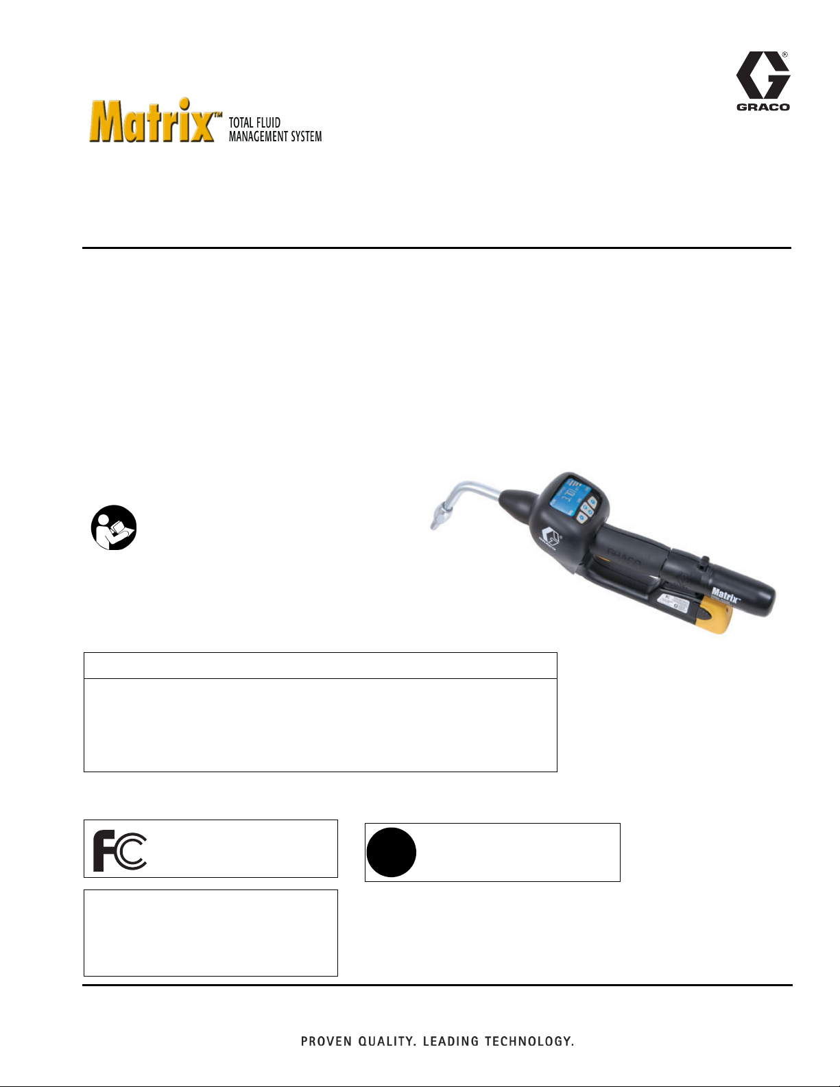
Matrix Meter
Used to dispense petroleum-based lubricants and antifreeze only.
Part No. 246008 Series D, North America (N. A.)
Part No. 249881 Series D, Australia
1500 psi (10.3 MPa, 103 bar) Maximum Working Pressure
600 psi (4.1 MPa, 41.4 bar) Maximum Dynamic Working Pressure (while dispensing)
5 gpm (18.9 lpm) Maximum Flow Rate
Important Safety Instructions
Read all warnings and instructions in this
manual. Save these instructions.
CAUTION
This dispense valve is:
• Designed to dispense petroleum-based lubricants and antifreeze ONLY.
• Designed for indoor use ONLY.
•NOT designed for in-line installation.
The Matrix Meter contains an RF device with the following approvals:
FCC ID: JHIGNET
IC: 4840AGNET
Industry Canada Statement
The term “IC” before the certification/registration number only signifies that the Industry Canada technical specifications
were met.
Australian Vendor Code: N3845
✓
Page 2
Manual Conventions
Contents
Manual Conventions . . . . . . . . . . . . . . . . . . . . . . . . 2
Warnings . . . . . . . . . . . . . . . . . . . . . . . . . . . . . . . . . 3
Programming the Meter . . . . . . . . . . . . . . . . . . . . . 4
Meter Programming . . . . . . . . . . . . . . . . . . . . . . 4
Meter Installation . . . . . . . . . . . . . . . . . . . . . . . . . 6
Pressure Relief Procedure . . . . . . . . . . . . . . . . . 8
Grounding . . . . . . . . . . . . . . . . . . . . . . . . . . . . . . 8
Pre-installation Procedure . . . . . . . . . . . . . . . . . . 8
Installing Nozzle Extension . . . . . . . . . . . . . . . . . 9
Meter Installation to Hose . . . . . . . . . . . . . . . . . . 9
Pressurizing the System . . . . . . . . . . . . . . . . . . . 9
Meter Operation . . . . . . . . . . . . . . . . . . . . . . . . . . . 10
Asleep/Awake Mode . . . . . . . . . . . . . . . . . . . . . 10
High/Low Flow Rate Indicator . . . . . . . . . . . . . . 10
Battery Life Indicator . . . . . . . . . . . . . . . . . . . . . 10
Security Modes . . . . . . . . . . . . . . . . . . . . . . . . . 11
Work Orders and Job Numbers . . . . . . . . . . . . 12
Dispense Options . . . . . . . . . . . . . . . . . . . . . . . 14
Manual Dispense Mode . . . . . . . . . . . . . . . . . . 14
Preset Dispense Mode . . . . . . . . . . . . . . . . . . . 14
Restricted Preset Dispense Mode . . . . . . . . . . 15
Removing and Replacing the Battery . . . . . . . . 15
Quick-Lock
™
Nozzle . . . . . . . . . . . . . . . . . . . . . 15
Troubleshooting . . . . . . . . . . . . . . . . . . . . . . . . . . . 16
Calculating the Calibration Factor . . . . . . . . . . . . 19
Service . . . . . . . . . . . . . . . . . . . . . . . . . . . . . . . . . . 21
Replacing or Cleaning Filter . . . . . . . . . . . . . . . 21
Replacing Quick-lock
Replacing the Bezel . . . . . . . . . . . . . . . . . . . . . . 22
Replacing the Trigger . . . . . . . . . . . . . . . . . . . . . 24
Replacing the Meter Electronics . . . . . . . . . . . . 28
Parts Drawing for the 246008 and 249881
Electronic Meters . . . . . . . . . . . . . . . . . . . . . . . 32
Parts List for the 246008 and 249881
Electronic Meters . . . . . . . . . . . . . . . . . . . . . . . 33
Nozzle Extension Accessories . . . . . . . . . . . . . . . 34
Kit 246005 . . . . . . . . . . . . . . . . . . . . . . . . . . . . . 34
Kit 246006 . . . . . . . . . . . . . . . . . . . . . . . . . . . . . 34
Kit 246007 . . . . . . . . . . . . . . . . . . . . . . . . . . . . . 34
Technical Specifications . . . . . . . . . . . . . . . . . . . . 35
Dimensions . . . . . . . . . . . . . . . . . . . . . . . . . . . . . . . 37
Graco Standard Warranty . . . . . . . . . . . . . . . . . . . 38
Graco Phone Numbers . . . . . . . . . . . . . . . . . . . . . 38
™
Nozzle . . . . . . . . . . . . . 21
Manual Conventions
WARNING
WARNING indicates a potentially hazardous situation
which, if not avoided, could result in death or serious
injury.
CAUTION
CAUTION indicates a potentially hazardous situation
which, if not avoided, may result in property damage or
destruction of equipment.
Note
A note indicates additional helpful information.
2 309497L
Page 3
Warnings
Warnings
The following warnings include general safety information for this equipment. More specific warnings are included in
the text where appropriate.
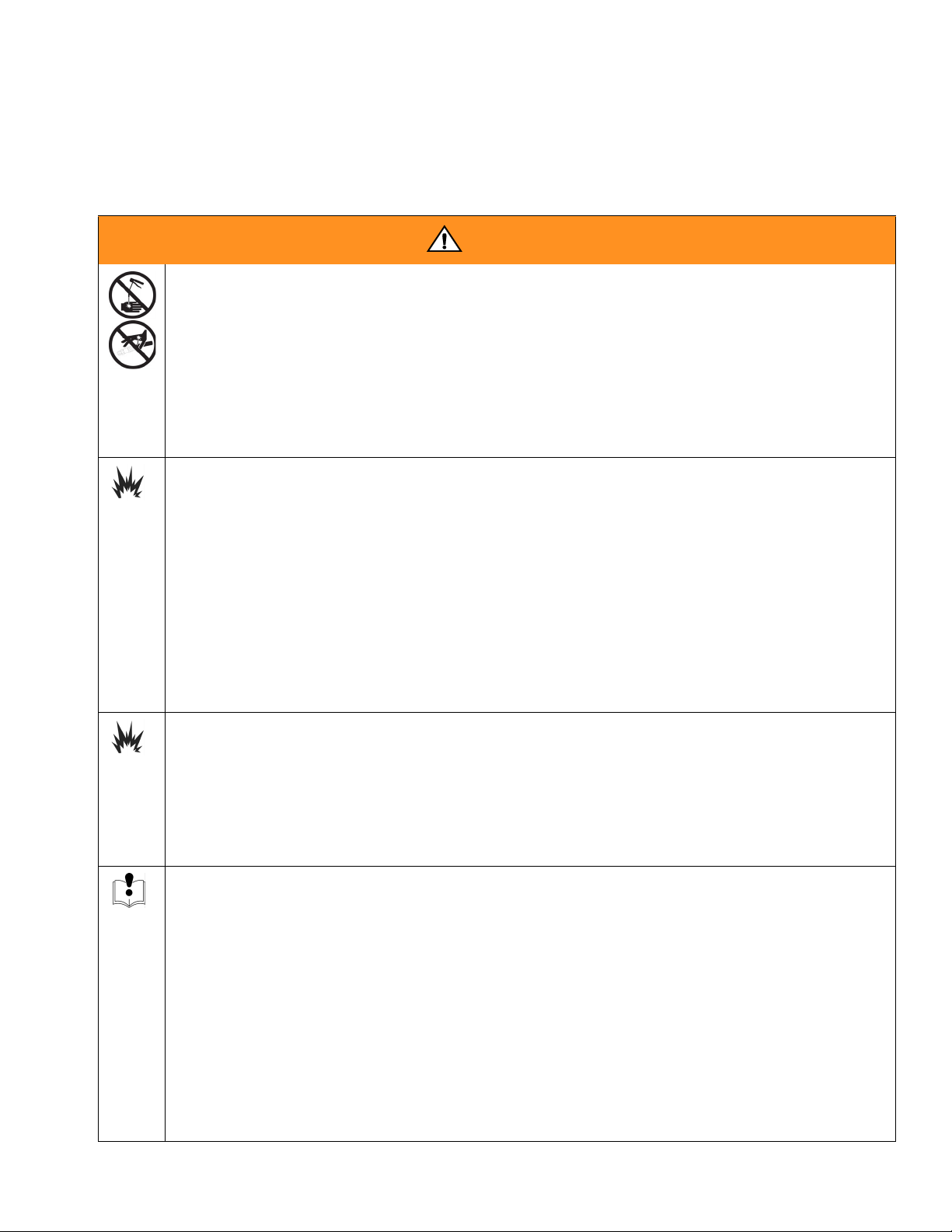
WARNING
SKIN INJECTION HAZARD
High-pressure fluid from dispense valve, hose leaks, or ruptured components will pierce skin. This may
look like just a cut, but it is a serious injury that can result in amputation. Get immediate surgical treat-
ment.
• Do not point dispense valve at anyone or at any part of the body.
• Do not put your hand over the end of the dispense nozzle.
• Do not stop or deflect leaks with your hand, body, glove, or rag.
• Follow Pressure Relief Procedure in this manual, when you stop spraying and before cleaning,
checking, or servicing equipment.
FIRE AND EXPLOSION HAZARD
When flammable fluids are present in the work area, such as gasoline and windshield wiper fluid, be
aware that flammable fumes can ignite or explode. To help prevent fire and explosion:
• Use equipment only in well ventilated area.
• Eliminate all ignition sources, such as cigarettes and portable electric lamps.
• Keep work area free of debris, including rags and spilled or open containers of solvent and gasoline.
• Do not plug or unplug power cords or turn lights on or off when flammable fumes are present.
• Ground equipment.
• Use only grounded hoses.
• If there is static sparking or you feel a shock, stop operation immediately. Do not use equipment
until you identify and correct the problem.
• Keep a fire extinguisher in the work area.
BATTERY SAFETY
The battery may leak, explode, cause burns, or cause an explosion if mishandled:
• You must use the battery type specified for use with the equipment.
• Sparking can occur when changing batteries. Only replace the battery in a non-hazardous location,
away from flammable fluids or fumes.
• Handle and dispose of battery properly - do not short circuit, charge, force over discharge, disassemble, crush, penetrate, incinerate, or heat the battery to a temperature exceeding 185° F (85° C).
EQUIPMENT MISUSE HAZARD
Misuse can cause death or serious injury.
• Do not exceed the maximum working pressure or temperature rating of the lowest rated system
component. See Technical Data in all equipment manuals.
• Use fluids and solvents that are compatible with equipment wetted parts. See Technical Data in all
equipment manuals. Read fluid and solvent manufacturer’s warnings.
• Check equipment daily. Repair or replace worn or damaged parts immediately.
• Do not alter or modify equipment.
• For professional use only.
• Use equipment only for its intended purpose. Call your Graco distributor for information.
• Route hoses and cables away from traffic areas, sharp edges, moving parts, and hot surfaces.
• Do not use hoses to pull equipment.
• Comply with all applicable safety regulations.
309497L 3
Page 4

Programming the Meter
Programming the Meter
Graco recommends that meters be programmed prior
to installation.
For ease of installation be sure to tag each meter with
the corresponding PC meter number from the Matrix
software. For example: Bay 1, 10W30. These tags are
used for locating the corresponding meter in the
assigned bay or location.
The electronic meter batteries need to be charged
prior to use. See Instruction Manual 309502 for
details.
Meter Programming
Prior to programming the electronic meters,
• Enter the transceiver and tank setup information into the Matrix PC software. If not done,
the software will display an error when attempting to set up meters.
• Navigate to the Meter Setup screen, input the
meter parameters, then select PROGRAM for
the meter being programmed.
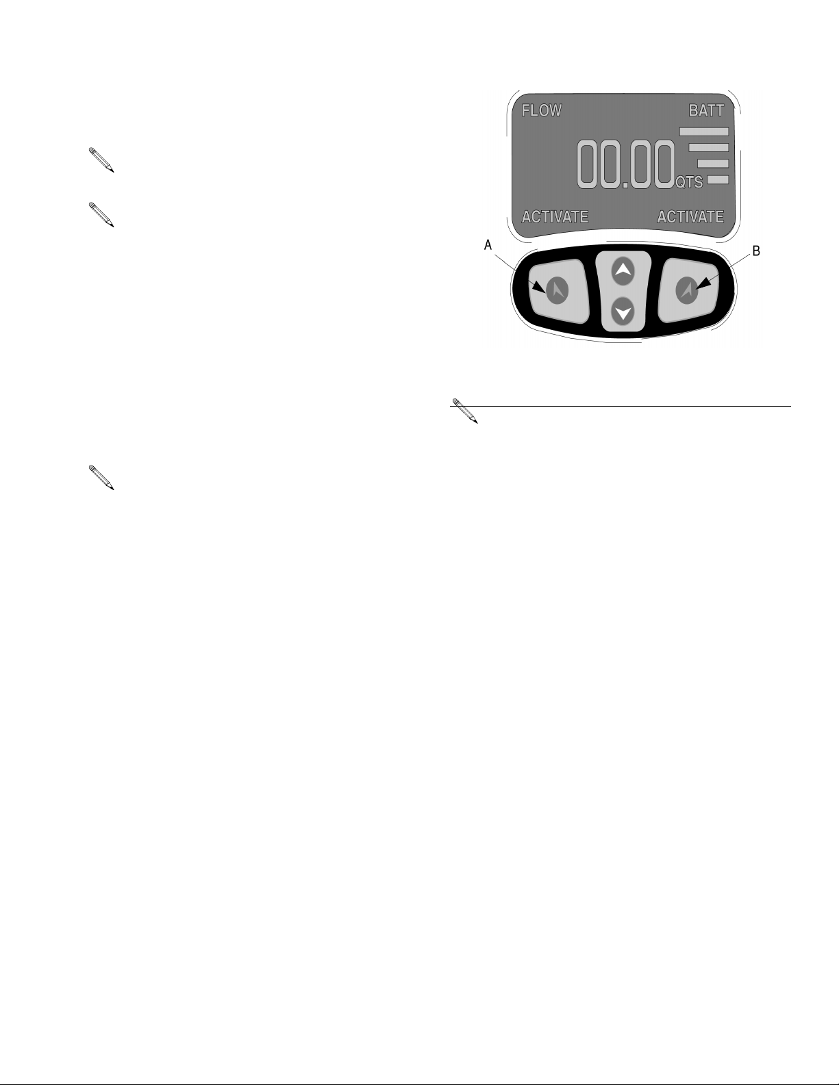
1. Insert the battery. See Removing and Replacing
the Battery on page 15.
2. When the battery is first inserted, the display shown
in F
IG. 2 appears.
3. To program a meter, simultaneously hold down both
the left keypad button (A) and right keypad button (B)
until both the ACTIVATE words on the display screen
change to PROGRAM (appears on the left) and
SELECT (appears on the right). Release buttons.
4. The screen indicates a Network and Transceiver ID.
See
FIG. 1
.
PROGRAM MODE
2.02.003
NET WK ID A
TRANS ID A
METER ID 500
PROGRAM
F
IG. 1
• If the ID information is correct, press the left (A) keypad button labeled PROGRAM to complete the
meter programming.
• If the ID information is incorrect, use the SELECT
button and up/down arrow button to obtain the correct ID settings. Then press the left (A) keypad button labeled PROGRAM to complete the meter
programming. See F
The meter must be at the ACTIVATE/ACTIVATE
screen for it to be programmed. If you are in Work
Order mode, put a test Work Order into the system
so you can navigate to the ACTIVATE/ACTIVATE
meter screen and re-program.
METER ID is the RF address assigned to the meter
by the PC during programming.
IG. 2.
SELECT
4 309497L
Page 5
5. The meter displays the appropriate programmed
screen and a pop-up window displays on the PC
indicating programming is complete. This process is
repeated for each meter in the system.
The PC software allows a 5 minute period to program the meter.
If the electronic meter is unable to communicate
with the PC during programming, the message NO
SIGNAL appears at the top of the meter display.
6. Once the information is programmed into the electronic meter, the meter can be connected to the dispensing hose in the corresponding bay. If the meter
will not be immediately connected temporarily label
it with the corresponding meter number and location
(i.e. Meter 1, Bay 1, 10W30). The label assures the
correct meter is installed in the correct location in
the system. After the meter is installed in the correct
location, the label can be removed. See Meter
Installation on page 6.
Programming the Meter
F
IG. 2
If PC software revision is 2.01.29 or meter firmware
revision is 2.00.053, meter will display 3 places to
the right of the decimal rather than 2.
If a programmed meter is moved or if the programmed parameters need to be changed, the
meter must be reprogrammed.
309497L 5
Page 6
Programming the Meter
Meter Installation
CAUTION
Failure to comply with the following installation
requirements may result in warranty coverage
being denied.
• Fluid lines MUST be thoroughly flushed before
installing Matrix meters
System, Instruction Manual 310652.
• All Matrix systems MUST use the Graco CleanLine System for initial flushing and ongoing operation for all service fluids. See CleanLine
Filtration System, Instruction Manual 310652.
• Pressure relief kits MUST be used on all pumps
within the Matrix system to prevent over-pressurization due to thermal expansion. See Pressure
Relief Kits, Instruction Manual 308403. Select
appropriate relief kits when using high pressure
(1600 psi) CleanLine filters. Low pressure (900
psi) CleanLine filters have a built-in pressure
relief valve.
. See CleanLine Filtration
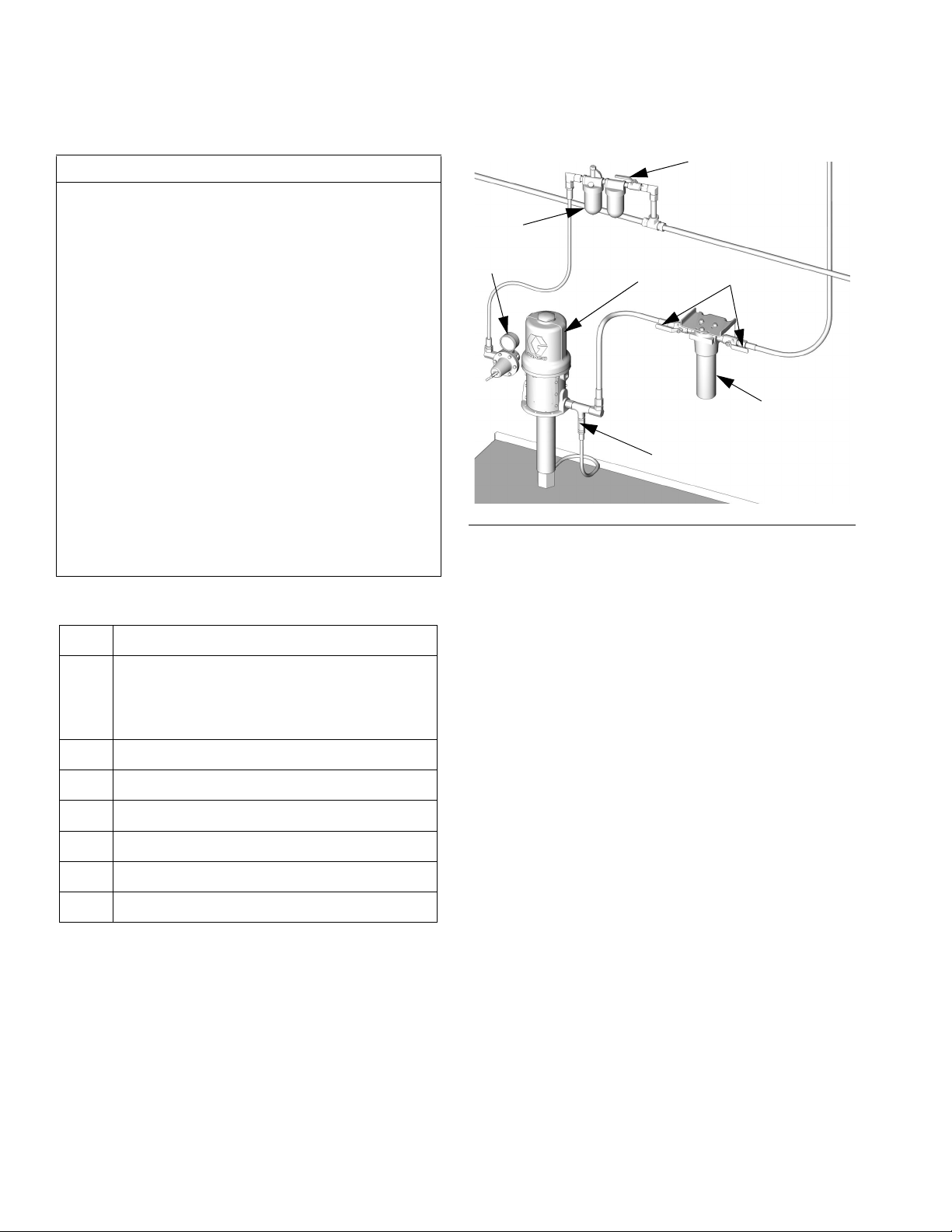
F
FIG. 3
K
J
H
D
E
G
ti5127
KEY DESCRIPTION, See F
Thermal Pressure Relief Kit must be
D
installed downstream from the pump. The
Thermal Pressure Relief Kit will vary based
on the pump selected
E Fluid shut-off valves (two)
F Air Regulator
G CleanLine Filter System
HPump * †
J Filter and Lubricator Assembly
K Master Bleed Air Valve (ball valve)
* Do not use diaphragm pumps in a Matrix system.
† Special pump packages are required for anti-
freeze. See instruction manual 310650.
IG. 3.
6 309497L
Page 7
F
IG. 4
Programming the Meter
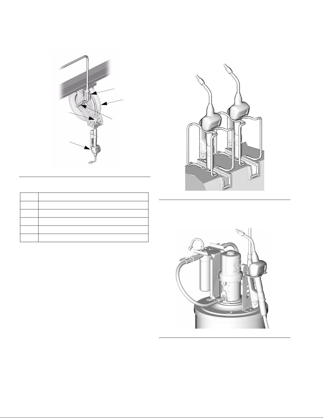
Mounting Brackets
Mounting bracket kit 249440 is available for resting a
Matrix meter on a console. See F
J
M
K
L
N
IG. 5.
KEY DESCRIPTION, See F
J Fluid shut-off valve
KHose
L Hose reel fluid inlet hose
M Hose reel
Electronic metered dispense valve
N
IG. 4.
ti6733
FIG. 5
Mounting bracket 15B750 is available for resting a
Matrix meter on a 16 gallon drum. See F
IG. 6
F
IG. 6.
ti6732
309497L 7
Page 8
Programming the Meter
Pressure Relief Procedure
WAR NING
Read warnings, page 3, and follow the Pressure
Relief Procedure whenever you:
• are instructed to relieve pressure
• stop operation
• check, clean, or service any of the equipment
1. Turn off the power supply to the pump.
2. Trigger the dispense valve into a waste container to
relieve pressure.
3. Open any bleed-type master air valves and fluid
drain valves in the system.
The Matrix meter must be powered, nozzle open
(counter clockwise), and in dispense mode for fluid
pressure to be relieved.
Pre-installation Procedure
1. Relieve the pressure. Follow the Pressure Relief
Procedure on page 8.
2. Close the shut-off valve (J). See F
3. Ground the hose and reel or console. See Ground-
ing.
4. If this is a new installation or if the fluid in the lines is
contaminated, flush the lines before you install the
metered valve.
CAUTION
Contaminated lines could cause the valve to leak.
Failure to flush may result in warranty coverage being
denied. See CleanLine Filtration System, Instruction
Manual 310652.
IG. 4.
4. Leave the drain valve open until you are ready to
pressurize the system.
Grounding
.
WARNING
The system must be properly grounded. Read warnings, page 3. Refer to the user manuals for the pump
and other system components, and ground the following:
• Pump: Follow the manufacturer's recommendations.
• Air and Fluid hoses: Use only grounded hoses.
• Air compressor: Follow the manufacturer's recommendations.
• Fluid supply container: Follow the local code.
• To maintain grounding continuity when flushing or
relieving pressure, always hold a metal part of the
valve firmly to the side of a grounded metal pail,
then trigger the valve.
8 309497L
Page 9
Programming the Meter
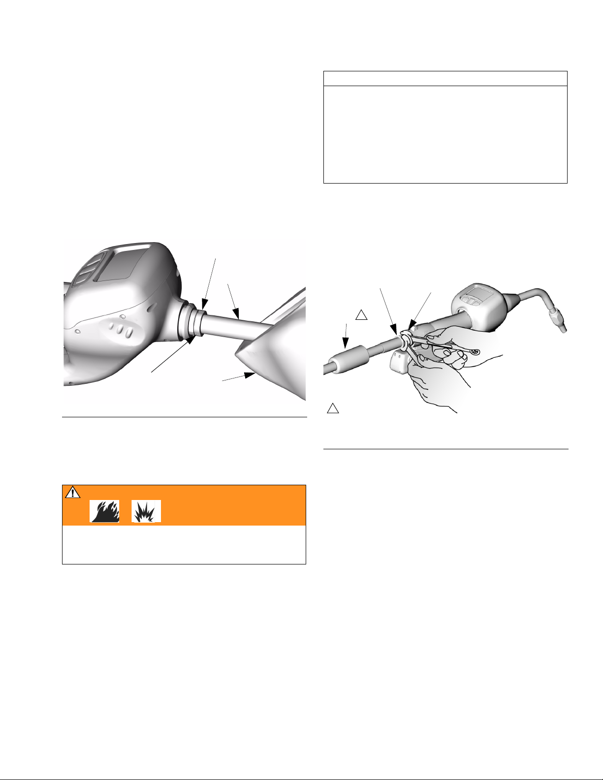
Installing Nozzle Extension
1. Slide the impact guard (40) onto the tube or hose of
the nozzle extension assembly. See F
2. Thread the sealing nut (101, 204, or 303) onto the
spout (102, 202, or 302).
3. Thread the tube or hose in at least three full turns,
position it for proper alignment, and wrench tighten
the sealing nut. The PTFE seal on the sealing nut
must face the valve housing. See F
4. Slide the impact guard (40) over the meter body.
101, 204, or 303
IG. 7.
IG. 7.
102, 202, or 302
CAUTION
Graco recommends using PTFE tape on hose threads
prior to installing the Matrix meter. PTFE tape should
be after the leading thread and clockwise (same direction as meter installs on hose fitting). Caution should
be taken not to get tape into the meter during installation as this can cause the meter to malfunction.
Should the tape be the cause of the malfunction,
Graco warranty will be denied.
2. Apply PTFE tape to the male threads of the hose fitting (P). See caution above. Leave a minimum of
two engaged threads bare to maintain grounding
continuity.
24
P
1
29
wrench tighten to
40
prevent leakage
F
IG. 7
Meter Installation to Hose
1. Slide the rear boot (24) onto the hose. See FIG. 8.
WARNING
Improper grounding can cause a hazardous condition
and result in fire or explosion. Follow instructions in
step 2 to maintain grounding continuity.
1
Slide boot onto
hose before connecting hose
F
IG. 8
ti64317
3. Thread the hose fitting into the swivel (29) of the
meter, and tighten it firmly. See FIG. 8.
4. Slide the rear boot (24) over the fittings and onto the
end of the Matrix meter.
Pressurizing the System
1. Open all dispense position shut-off valves. Start the
pump to pressurize the system. See the Operation
section, page 14, for proper operation of meter.
2. To ensure dispensing accuracy, purge all air from
the fluid lines and dispense valve before using it.
3. Set the system flow to the desired flow rate, which is
typically 1.5-gpm. Do not exceed a 5-gpm flow rate.
309497L 9
Page 10
Meter Operation
Meter Operation
Asleep / Awake Mode
Asleep is a battery-saving mode in which the display
goes blank after two minutes of inactivity during normal
operation. The display comes Awake from sleep mode
when any button is pressed.
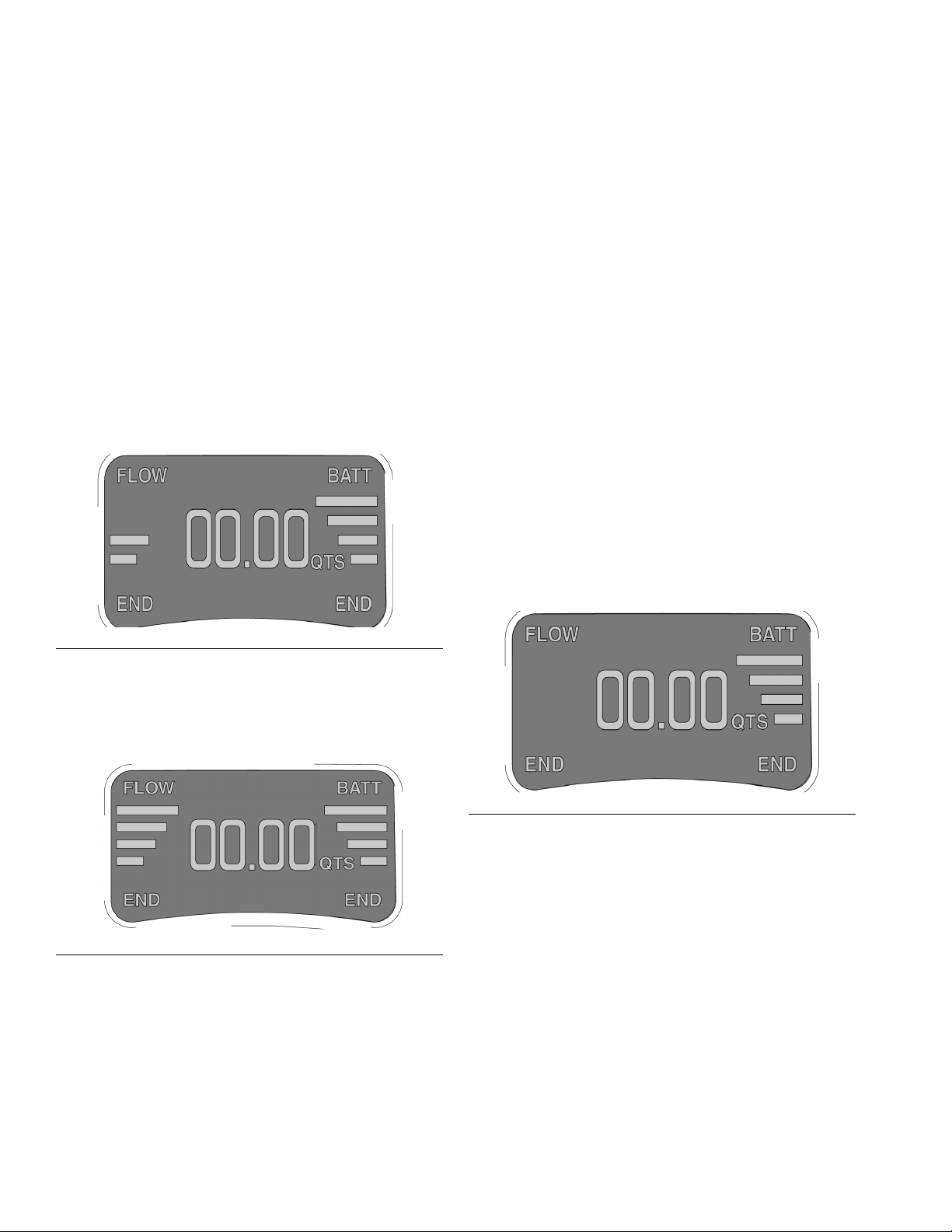
High/Low Flow Rate Indicator
The electronic meter dispenses fluids at two different
rates.
As the trigger is partially engaged, the flow rate is low
and is indicated by two bars on the display. See F
IG. 9.
Battery Life Indicator
On the right side of the display is a series of four bars
located under the word BATT. See F
ence of all four bars indicates a fully charged battery.
The bars decline in number as the meter is used and the
battery discharges. All Matrix meter batteries should be
re-charged at the end of the working day to assure good
performance the next work day.
• Batteries can be recharged at anytime without
battery damage.
• At one bar on the display you will have about
20-40% of the charge remaining.
• If a meter is removed from service for an
extended time the battery should be removed
and recharged.
• If you see the message “Remove Low Battery Wait 30 Seconds Then Replace”, remove the
battery, wait 30 seconds, and then replace it
with a charged battery.
• Even when a meter is idle (asleep), the meter is
still functioning and the battery will be used.
IG. 11. The pres-
F
IG. 9
• When the trigger is fully engaged, the flow rate is
high and is indicated by four bars on the display.
See F
IG. 10.
IG. 10
F
FIG. 11
10 309497L
Page 11

Security Modes
PIN CODE
RIGHTLEFT
2122
ENTER
AUTHORIZATION
REQUIRED
REQUEST
APPROVAL
REQUEST
APPROVAL
When the meters were originally programmed by the
system administrator, one of the following security
choices was entered:
• System Monitoring
•PIN Code
• Parts Room Authorization
Meter Operation
Prior to dispensing, it may be necessary to complete
one of the following security procedures, depending on
the security mode selected.
System Monitoring
When set for system monitoring, no security authorization is required by the operator. However, any amount of
fluid dispensed is automatically sent by the meter to the
PC where it is recorded for future reference.
PIN Code
PIN Code (personal identification number) means that a
four digit PIN code must be entered at the meter to
obtain dispense authorization. To use a meter with PIN
code security:
1. Use the up and down arrow keypad buttons to select
the first number of the PIN code.
2. Press the right keypad button to move the cursor to
the next position.
3. Use the up and down keypad buttons to select the
desired number. Continue this process until the PIN
code number is completed. See F
IG. 12.
F
IG. 12
4. When the pin code is complete, press the right keypad button until the cursor underlines the Enter
option. Press the up arrow on the meter keypad.
This action will enter the PIN code and send it to the
PC.
5. The PC recognizes the PIN code and authorizes the
meter to dispense.
Parts Room Authorization
This mode provides high level security and requires a
Parts Room Administrator to authorize each dispense.
AUTHORIZATION
REQUIRED
REQUEST
APPROVAL
IG. 13
F
REQUEST
APPROVAL
309497L 11
1. Press either the left keypad or right keypad button
under REQUEST APPROVAL. This sends the
request to the parts room administrator’s PC for dispense authorization. See F
2. The administrator grants authorization at the PC,
which then authorizes the meter to dispense.
IG. 13.
Page 12
Meter Operation
WORKORDER
SELECTSELECT
ENTER NEW
2ACO
-
32567
- IC9
2AC03
-
458A1
-
2233A
-
ENTER WORKORDER
RIGHTLEFT
WORKORDER JOB
ENTERCANCEL
2AC03
Work Orders and Job Numbers
When the meters were programmed by the System
Administrator, one of the two Work Order processing
methods below was selected.
• Work Order/Job Number at the PC only
• Work Order/Job Number at the PC and Meter
Work Orders are a maximum of (12) characters and the
Job Number is a maximum of (3) characters. The Work
Order number is separated from the Job Number with a
dash (-).
The characters A-Z, 0-9, dash (-); forward slash (/),
period (.), or space can be used when assigning a Work
Order or Job Number. One Work Order can have more
than one service using an extension in the order number
(i.e., 123456.oil, 123456.atf). The meter can receive up
to five (5) work orders at a time. See F
IG. 14.
Assigning Work Orders and Job Numbers
from the PC
Work Orders and Job Numbers are assigned to a meter
from the PC using the “Entering Work Orders” button in
the software. This feature is password protected.
1. Click on the Entering Work Orders button. Type in
the user name and password and click Submit.
1. At the Work Order/Job Number meter screen,
select the Enter New option using the up and down
keypad buttons. When the arrow is positioned prior
to the Enter New option, push either one of the two
outside keypad buttons to Select the option. This
will take you to a second screen to enter the Work
Order/Job Number. Matrix meters can display up to
5 work orders and the Enter New command. See
F
IG. 14.
ENTER NEW
2ACO 32567 - IC9
2AC03 458A1 2233A -
F
IG. 14
2. On the second Work Order/Job Number screen, the
cursor defaults to the first character position for
entering the Work Order (up to 12 characters). Use
the up and down keypad buttons to select a number,
letter, or character for the first digit of the Work
Order.
2. Click on the Add Work Order box. Select meter
from the pull down screen. Type in a Work Order (up
to 12 characters). Tab or mouse click to the Job
Number box and enter the Job Number (up to 3
characters) if desired, then click Send.
3. If the Work Order is received by the designated
meter, the PC Work Order list will be updated to
show “Dispense Pending” in the status column.
If the Work Order is not received by the meter, a pop-up
box appears indicating that the Work Order could not be
sent to the assigned meter. You then can click Retry or
Cancel.
Assigning Work Orders and Job Numbers
3. Press the right keypad button to move the cursor to
the next character position. Use the arrow keypad
buttons to select the character desired. Continue
this process until the Work Order is completed. See
F
IG. 15.
F
IG. 15
at the Meter
Work Orders and Job Numbers can be assigned at the
meter using the meter Work Order screen and meter
keypad buttons. The screen shows previously assigned
Work Orders and the Enter New option.
To enter a new Work Order follow the procedure below:
12 309497L
4. Press the right keypad button and navigate to the
first position to enter the Job Number if desired.
Enter the Job Number in the same manner as you
entered the Work Order number.
Page 13

Meter Operation
EMERGENCY MODE
RIGHTLEFT
1222
ENTER
5. When the numbers are complete, press the right
keypad button until the cursor underlines the Enter
option. Press the up arrow on the meter keypad
display. This action will enter the new Work Order to
the list on the first screen.
To Cancel a Work Order press either the right or
left keypad button on the meter until the cursor
underlines the Cancel option. Push the up arrow
on the keypad to cancel the Work Order entry. This
will take you back to the first Work Order/Job Number screen.
Work Order Validation Mode: The default operation
mode for either work order method is validation mode.
This mode is recommended for maximum protection
against unauthorized dispenses and maximum integrity
of the Matrix database.
Emergency Mode
If the communication link is lost (power loss, computer
crash), the meters will continue to function if they are
placed in the Emergency Mode.
During Emergency Mode, the meter continues to
store dispense history and will communicate this
information to the PC when the communication link
is restored.
Placing a Meter in the Emergency Mode
The Emergency Code Number must be provided by the
system administrator before performing this procedure.
1. Select the meter(s) to place in the Emergency
Mode.
2. Simultaneously hold down both the left and right
keypad buttons until ACTIVATE appears in the
lower left and right corners of the meter display.
3. Press the UP arrow keypad button once which takes
you to the Emergency Mode screen.
4. Enter the four-digit Emergency Code Number. Position the cursor under the word ENTER and press
the UP arrow on the keypad. Meter security is
bypassed and the meter is now in the Emergency
Mode. This procedure must be repeated for each
meter placed into the Emergency Mode.
5. When communication is restored, each meter
placed into Emergency Mode must be re-pro-
grammed with its original settings.
After the meter is placed in Emergency Mode, the
battery must remain in the meter until the display
goes blank. If not, the meter will revert to it’s original programming.
F
IG. 16
309497L 13
Page 14

Meter Operation
Dispense Options
The meter dispense options are determined by the system administrator at the time the meter is programmed.
Meter dispense options include:
• Manual Dispense Mode
• Preset Dispense Mode
• Restricted Preset Dispense Mode
To change the meter from one mode to another,
you must reprogram the meter. See Programming
the Meter on page 4.
Manual Dispense Mode
To dispense fluids in this mode:
1. If necessary, enter the PIN code, Parts Room
Authorization request and/or the Work Order
request.
2. Press the left or right keypad button under ACTIVATE to begin communication with the PC. Both
ACTIVATE words on the display screen will change
to END.
3. Pull the meter trigger to dispense. The meter counts
up to the desired amount.
4. Release the trigger when the desired amount is
obtained. Then press the right or left keypad button
to end the dispense. This logs the dispense amount
to the PC and returns the meter to its programmed
entry screen.
If END is not pressed, after five minutes the meter
will automatically end the job and log the dispense
to the PC.
Preset Dispense Mode
Meters programmed in preset mode count down from a
specified value to zero and shut off automatically. The
preset value can be increased or decreased from the initial value using the up and down keypad buttons.
1. If necessary, enter the PIN code, Parts Room
Authorization request and/or work order request.
2. Press ACTIVATE to enter the dispense mode. The
preset default amount entered into the PC will
appear on the meter.
F
IG. 17
3. If desired press the arrow up or arrow down keypad
button to change the preset amount.
4. Press the right keypad button under the word
CLEAR to zero out the preset amount. The arrow up
and arrow down keypad buttons are used to enter a
new amount of fluid to dispense.
5. Pull and release the meter trigger to start the dispense. The meter dispenses the preset amount and
shuts off.
Flow can be stopped at any time during the dispense by
pressing the meter trigger or any button on the meter
display.
See FIG. 17.
OR
An appropriate preset amount can be set for each
work order when entering work orders at the PC.
Once the preset amount is dispensed, the meter display
automatically changes to read TOP OFF MODE. This
allows the operator to add additional fluid after the preset amount is dispensed. The Top Off amount to be dispensed can be limited during meter programming. See
F
IG. 18.
14 309497L
Page 15

Meter Operation
F
IG. 18
6. If the operator wants to top-off fluids, press the left
arrow key to display the TOP-OFF MODE. See F
IG.
19.
Removing and Replacing the
Battery
1. Remove the battery by pressing in on both battery
lock buttons (E) and pulling the battery (F) out and
away from the meter. See F
2. Place the battery in the battery charger. See
Instruction Manual 309502 for details.
3. Replace the battery by pressing in on both battery
lock buttons (E) and pushing the battery (F) into the
meter.
If the meter displays a low battery warning, wait 30
seconds before installing a new battery. See Battery Life Indicator page 10.
.
E
IG. 20.
IG. 19
F
7. Pull the trigger to dispense the desired fluid amount
for top-off.
8. Press END to complete the job. See F
IG. 19. This
logs the dispense to the PC and returns the meter to
its programmed entry screen.
If END is not pressed, after 5 minutes the meter will
time out and log the dispense to the PC.
Restricted Preset Dispense
Mode
When meters are programmed in restricted preset
mode, the specified dispense value cannot be
increased, only decreased. The functionality of this feature is identical to Preset Dispense Mode (see Preset
Dispense Mode beginning on page 14) except that the
preset value can only decreased with the down keypad
button.
F
IG. 20
F
ti64318
Quick-Lock™ Nozzle
The nozzle opens and closes with LESS THAN
one turn.
1. To close the nozzle to prevent dripping, rotate left
(counter clockwise) until tight. See F
2. To open the nozzle for dispensing, rotate right
(clockwise) until fully open.
IG. 21.
Open
Close
ti64319
F
IG. 21
309497L 15
Page 16

Troubleshooting
Troubleshooting
WAR NING
Read warnings, page 3.
Problem Cause Solution
Battery display
bars do not appear.
Meter display does
not activate.
Slow or no fluid
flow from meter.
Battery has low charge. Recharge battery.
Battery is dead. Attempt to recharge a dead battery using procedures
Battery inserted too soon. Wait 30 seconds and reinstall fully charged battery.
Cable connections are loose or disconnected.
Electronic display is damaged.
CleanLine filter system is clogged. Clean or replace the CleanLine filter. Refer to the Clean-
Meter is not in dispense mode. See dispense options, page 14.
Matrix meter filter is clogged. Clean or replace the Matrix meter filter element. See
Pump pressure is low. Turn up air pressure to the pump. SeeTechnical Speci-
Pump or reel fluid shut-off valve is
not fully open.
Meter hydraulic valve is not functioning.
Electronic board connections may be
loose or disconnected.
Trigger membrane switch is damaged - flow bars DO NOT show on
the meter display when the trigger IS
actuated.
Meter valve is blocked with debris flow bars DO show on the meter display when trigger IS actuated.
Quick close nozzle is closed. Open nozzle, see F
A hydraulic quick disconnect was
used to connect the meter to the dispense hose, allowing debris to clog
meter.
Relieve pressure before you check or repair the meter.
Follow the Pressure Relief Procedure, page 8.
Be sure all other valves and controls and the pump are
operating properly. If using the chart below to troubleshoot is not successful, contact your Graco distributor
for repairs or component replacement.
outlined in the Battery Charger Instruction Manual
(309502). If procedure does not restore a normal
charge, replace the battery.
Ensure cables are properly connected. See page 22.
Replace with Bezel Repair Kit (246438). See page 33.
Line Filter System Instruction Manual (310652).
Cleaning or Replacing the FIlter page 21.
fications page 35.
Fully open pump or reel fluid shut-off valve.
If meter bars are lit indicating flow, the nozzle tip is fully
open, and the fluid flow has been verified to the meter
valve inlet, then the meter hydraulic valve has failed and
the meter should be replaced.
Verify that all connectors are connected or re-seated to
the board connections. See page 22.
Replace the trigger membrane using the Trigger Repair
Kit (246439 N. A., 249883 Australia). See page 33.
Flush the valve with mineral spirits at high pressure and
flow. Warning: do not exceed the maximum working
pressure of the meter (1500psi - 103 bar).
IG. 21 on page 15.
Quick disconnects should not be used with Matrix product, doing so voids the warranty.
16 309497L
Page 17

Problem Cause Solution
Meter does not
stop dispensing.
Meter valve is blocked with debris flow bars DO NOT show on the meter
display when the trigger IS NOT actuated.
Flush the valve with mineral spirits at high pressure and
flow. Warning: Do not exceed the maximum working
pressure of the meter (1500 psi - 103 bar). If flushing
does not resolve the problem, the meter should be
replaced.
Trigger or trigger membrane switch is
damaged - flow bars DO show on the
meter display when the trigger IS
NOT actuated.
Dynamic System Pressure (while dispensing) exceeds the recommended
Replace the trigger and trigger membrane using the
Trigger Repair Kit (246439 N. A., 249883 Australia). See
page 33. Do not use clamps or wire ties to hold trigger
during dispense, doing so voids the warranty.
Reduce system pressure. A lower ratio pump may be
required to reduce pressure and maintain sufficient flow.
600 psi (4.1 MPa, 41.4 bar).
A hydraulic quick disconnect was
used to connect the meter to the dis-
Do not use quick disconnects with Matrix product. Use
of quick disconnects voids the warranty.
pense hose, allowing debris to block
meter.
Displayed dispensed amount is
not accurate.
Meter will not take
work orders.
Meter is not programmed for the cor-
Verify meter programming.
rect fluid type.
Meter gears are worn. Meter requires calibration due to wear. See page 19.
Battery has low charge or is dead. Recharge battery.
Battery inserted too soon. Wait 30 seconds and reinstall fully charged battery.
Meter may not be programmed. Reprogram meter.
Battery may have been pulled during
Reprogram meter.
programming.
Two meters may be programmed as
Ensure each meter is programmed individually.
the same meter.
Meter work order list is full. Normal operation. Meter will hold up to 5 work orders.
Meter has intermittent or no RF communication.
Meter is outside RF communication
range of transceiver.
Two meters may be programmed as
Reposition transceiver or add a transceiver.
Ensure each meter is programmed individually.
the same meter.
PC or transceiver is off. Turn PC on, open Matrix application, and check power
on transceiver.
Meter will not program.
Incorrect COM port selected for
transceiver connection.
Change to correct COM port at the PC in Matrix trans-
ceiver configuration screen.
Transceiver is not powered up. Power up transceiver, wait 30 seconds or until red lights
go blank and green light remains on alone.
Transceiver dip switches are not set
See transceiver manual 309498 to set dip switches.
for the communication cable being
used.
Matrix program is not in programming
mode.
The five-minute programming session has expired.
Network and transceiver settings on
the meter are not correctly set.
Meter is outside RF communication
Place PC in programming mode. See Programming the
Meter, page 4.
Place PC in programming mode. See Programming the
Meter, page 4.
Make appropriate settings. See Programming the Meter,
page 4.
Reposition transceiver or add a transceiver.
range of transceiver.
Troubleshooting
309497L 17
Page 18

Troubleshooting
Problem Cause Solution
Meter has been in
service for an
extended period of
time and begins to
work erratically
such as loss of
Work Orders or
Security settings.
Meter leaks. Extension may be loose from meter
Meter cuts on and
off during preset
dispense.
Meter displays
“active trig”
E-Prom on meter board has reached
the end of its life.
fluid housing.
Swivel connection at hose may be
leaking.
The trigger is being held during preset dispense.
Trigger or trigger membrane switch is
damaged - flow bars DO show on the
meter display when the trigger IS
NOT actuated.
Trigger or trigger membrane switch is
damaged - flow bars DO show on the
meter display when the trigger IS
NOT actuated.
Trigger is being held before activating
meter for dispense.
Attempt to reprogram the meter. If you see a pop-up
screen on the PC that says, “Memory Failure” and/or the
meter screen defaults to the ACTIVATE/ACTIVATE
screen, the E-Prom on the meter board must be
changed. Install the Electronics Repair Kit (246675).
The Electronics Repair Kit includes a new meter board
with E-Prom. The meter then can be reprogrammed to
the features desired.
Tighten seal nut using two wrenches.
Clean, seal, and tighten joint.
Release the trigger during preset dispense.
Replace the trigger and trigger membrane using the
Trigger Repair Kit (246439 N. A., 249883 Australia). See
page 33. Do not use clamps or wire ties to hold trigger
during dispense, doing so voids the warranty.
Replace the trigger and trigger membrane using the
Trigger Repair Kit (246439). See page 33. Do not use
clamps or wire ties to hold trigger during dispense, doing
so voids the warranty.
Release trigger to activate meter.
* To use the Matrix Emergency Mode contact the Matrix System Administrator in your facility.
18 309497L
Page 19

Calculating the Calibration Factor
Calculating the Calibration Factor
Use the following tables and formulas to calculate the change to the calibration factor.
Example of Calibration Adjustment for Motor Oil (quarts - 368)
Dispense into a clean, calibrated, volumetric measuring flask until the meter display indicates 1 quart of fluid has
been dispensed.
For greater accuracy, submerge the nozzle and let the air settle out of the fluid for ten minutes before noting the
volume.
• In the following example, the flask shows the volume is less than one quart (-1.2 ounces). See the left column
and find the number closest to -1.2 ounce value which is 1.0.
• Look for the corresponding number in the right column, which is +12. If the current calibration factor is 368, add
12 to get the new calibration factor of 380.
• Change this factor for a fluid in Tank Setup and for given meter(s) in Meter Setup.
Metric Measurement
Measuring in liters, and 1 liter is dispensed
Error in Milliliters (ml) Change Calibration
Factor by:
+ 50 - 20 + 1.7 - 20
+ 40 - 16 + 1.4 - 16
+ 30 - 12 + 1.0 - 12
+ 20 - 8 + 0.68 - 8
+ 10 - 4 + 0.34 - 4
+ 0 no change 0 no change
- 10 + 4 - 0.34 + 4
- 20 + 8 - 0.68 + 8
- 30 + 12 - 1.0 + 12
- 40 + 16 - 1.4 + 16
- 50 + 20 - 1.7 + 20
The table on the right lists approximate calibration factors for different fluids. Your calibration number may vary
slightly due to temperature or flow rate.
U.S. Measurement
Measuring in quarts, and 1 quart is dispensed
Error in U.S. ounces
(oz.)
Fluid
Oil (10W-30) 368 389
Gear Lube 375 396
Automatic Transmission Fluid 368 389
Antifreeze 348 368
Change Calibration
Factor by:
Calibration
Number
Quarts Liters
309497L 19
Page 20

20 309497L
Page 21

Service
WAR NING
Service
29
6
9
Read warnings, page 3.
Follow the Pressure Relief Procedure, page 8,
whenever you:
• are instructed to relieve pressure
• stop operation
• check, clean, or service any of the equipment
The low-battery and dead-battery displays are explained
in the Troubleshooting chart on page 16.
To change the battery see Removing and Replacing
the Battery on page 15.
Replacing or Cleaning Filter
To replace or clean the filter, do the following:
1. Relieve the pressure.
2. Unscrew the hose from the swivel (29). See F
3. Remove the o-ring (6), and remove the filter (9) from
its seat in the swivel (29) with an o-ring pick.
IG. 22.
m
a
e
r
t
s
n
w
o
D
ti64320
FIG. 22
Replacing Quick-lock™ Nozzle
The quick-lock nozzle (101, 201, or 301) is not serviceable. If the nozzle leaks, replace it as follows. See F
23.
1. Remove the old nozzle from the extension with an
open-end adjustable wrench on the flats (A) of the
nozzle stem.
2. Thread the new nozzle (101, 201, or 301) onto the
extension. With an open-end adjustable wrench on
the flats (A) of the nozzle stem, firmly tighten the
nozzle. the flats (A) of the nozzle stem, firmly tighten
the nozzle.
101
IG.
4. Thoroughly clean the filter with solvent, or replace
with the new filter.
5. Push the new or cleaned filter (9) into the swivel
(29), and make sure it’s properly seated. Replace
ti64328
A
the o-ring (6).
Be sure to position the new filter (9) so the concave
side of the screen points downstream. See
6. Screw the hose back into the swivel (29).
309497L 21
FIG. 22
.
F
IG. 23
201
301
ti64329
A
A
ti64330
Page 22

Service
Replacing the Bezel
Bezel Repair Kit 246438 is available and can be ordered
separately. See the Parts List for the 246008 and
249881 Electronic Meters on page 33. The parts with a
★ next to their reference numbers are included in this
repair kit.
12
When repairing the meter using the Bezel Repair Kit, be
sure to use all of the new parts. To replace the parts do
the following.
CAUTION
Be sure to use the disposable grounding wrist strap
included with the repair kit. Static electricity can damage the electrical components as the meter is
repaired.
1. Relieve the Pressure.
WARNING
To reduce the risk of serious injury whenever you are
instructed to relieve pressure, always follow the Pressure
Relief Procedure on page 8.
2. Remove the battery (11). See Parts Drawing for
the 246008 and 249881 Electronic Meters on
page 32.
42 (both sides)
FIG. 24
8. Pull apart the two cover halves leaving all parts in
the right cover half (18). See F
All services to the meter should be done using the
right cover half (18) of the meter. If parts should disengage as the covers are separated, reposition the parts
back into the right cover half (18).
19
IG. 25.
18
3. Slide the rear boot (24) off the hose.
4. Remove the meter from the fluid hose.
F
5. Remove the impact guard (40) from the meter.
6. With a phillips screwdriver remove the four phillips
screws (42) holding the bezel to the cover halves
(18 & 19). See F
7. With a T-10 torx driver remove the remaining eleven
screws (12) holding the cover halves together (18 &
19).
22 309497L
IG. 24.
IG. 25
Page 23

9. Pull the bezel (31) away and up from the right cover
half (18). See F
IG. 26.
Service
When reconnecting cable C to the circuit board
(112), ensure that the cable is positioned with the white
tab facing up and that the cable is straight before pushing in (closing) the clasp. See F
IG. 28.
IG. 26
F
C
B
A
F
IG. 27
10. Disconnect the cables/wires (A, B, & C) that connect
the bezel (31) to the circuit board (112). Discard the
old bezel (31). See F
IG. 27 and FIG. 28.
FIG. 28
12. Replace the bezel (31) onto the right meter cover
half (18).
Ensure that all meter parts are positioned securely
and in the correct location. Ensure that all cables are
routed correctly throughout the meter and will not be
pinched or kinked when the halves are reassembled
See F
IG. 29 and FIG. 30.
Ensure that the black antenna wire is not positioned between the ribbon cables. Pull antenna away
from the cable as shown. See F
IG. 31.
11. Reconnect the cables/wires (A, B, & C) from the
new bezel (31) to the circuit board (112).
309497L 23
Page 24

Service
F
IG. 29
13. Assemble the covers (18 & 19). Insert several of the
screws (12) to temporarily hold the cover halves (18
& 19) together. Test the display by inserting a battery (11) and powering on the unit.
If the display does not appear:
• make sure that a charged battery (11) is being
used.
• check that the connections from the new bezel
(31) to the circuit board (112) are fastened correctly and securely.
• check that all remaining parts are repositioned
securely and in the correct location.
14. If the display appears and is operating correctly,
replace the remaining screws (12) and (42) that fasten the cover halves (18 & 19) together. Torque all
screws to 7 - 10 in. lbs.
15. Replace the rear boot (24) and impact guard (40).
IG. 30
F
16. Attach the meter to the fluid line by following steps
listed on page 9.
Replacing the Trigger
Trigger Repair Kits 246439 for meter 246008 and
249883 for meter 249881 are available and can be
ordered separately. See the Parts List for the 246008
and 249881 Electronic Meters on page 33. The parts
with a ✓ next to their reference numbers are included in
this repair kit.
The PSM switch (101) comes attached to the right
meter cover half (18). Do not remove it during the
meter cover repair procedure.
When repairing the meter using the Trigger Repair Kit,
use all of the new parts. To replace the parts do the fol-
lowing.
CAUTION
Be sure to use the disposable grounding wrist strap
included with the repair kit. Static electricity can damage the electrical components within the meter as the
repair is completed.
IG. 31
F
24 309497L
Page 25

1. Relieve the Pressure.
WARNING
To reduce the risk of serious injury whenever you are
instructed to relieve pressure, always follow the Pressure
Relief Procedure on page 8.
1. Remove the battery (11). See Parts Drawing for
the 246008 and 249881 Electronic Meters on
page 32.
2. Slide the rear boot (24) off the hose.
3. Remove the meter from the fluid hose.
4. Remove the impact guard (40) from the meter.
5. With a phillips screwdriver remove the four phillips
screws (42) holding the bezel to the cover halves
(18 & 19). See F
IG. 32.
6. With a T-10 torx driver remove the remaining eleven
screws (12) holding the cover halves together (18 &
19).
All services to the meter should be done using the
right cover half (18) of the meter. If parts should disengage as the covers are separated, reposition the parts
back into the right cover half (18). See F
IG. 33.
19
18
IG. 33
F
8. Place the new right cover (18) along side of the
meter.
Service
12
42 (both sides)
FIG. 32
7. Pull apart the two cover halves leaving all parts in
the right cover half (18).
9. Remove the old trigger components (13, 14, 22, 23,
36, & 37) and discard.
246008 and 249881 Electronic Meters
See
Parts Drawing for the
on page 32.
10. Remove the RF Board (103) from the right meter
housing (18) and disconnect the PSM switch (101)
by pulling the cable from the RF Board (103). See
F
IG. 35.
11. Plug connector end of the new PSM switch (101)
into the new RF Board (103) connector.
12. Transfer all remaining parts from the old meter cover
half (18) to the new meter cover half (18). Discard
the old meter cover halves (18) and (19).
13. The two ribs (E) of the new meter cover fit
between the two bolts (F) of the meter housing. Be
sure not to pinch or crimp the circular switch cable
(D) on the new cover half. See F
IG. 34.
309497L 25
Page 26

Service
D
F
F
E
E
IG. 34
F
14. Insert the RF Board (103) into the new right meter
half (18). See F
IG. 35.
Ensure that the RF Board (103) is positioned
securely in the slots (A) of the new right meter half (18).
See F
IG. 35.
101
A
23
37
ti4323
FIG. 36
16. Make sure that all other meter parts are positioned
securely and in the correct location. See F
IG. 37.
IG. 37
F
17. Attach the bezel (31) to the right meter housing (18).
103
F
IG. 35
Ensure that all meter parts are positioned securely
and in the correct location. Ensure that all cables
15. Slide the trigger assembly (13, 14, 22, 23, 36, & 37)
back onto the mounting peg on the right half of the
meter (18). See F
IG. 36.
are routed correctly throughout the meter and will
not be pinched or kinked when the halves are reassembled See F
IG. 38 and FIG. 39.
Ensure that the circular trigger plunger (23) is centered with the trigger switch. Also ensure that the trigger
spring (37) is securely slid into position. See F
26 309497L
IG. 36.
Page 27

Ensure that the black antenna wire is not positioned
between the ribbon cables. Pull antenna away from
the cable as shown. See F
F
IG. 38
IG. 40.
Service
FIG. 40
18. Assemble the covers (18 &19). Insert several of the
screws to hold the cover halves together. Test the
display and trigger by inserting a battery and powering on the unit. If display does not appear or trigger
does not function:
F
IG. 39
• make sure that a charged battery (11) is being
used.
• check that the connections from the new bezel
(31) to the circuit board (112) are fastened correctly and securely.
• check that all parts are repositioned securely
and in the correct location.
• check that the trigger connection to the RF
board (103) is fastened correctly and securely.
• check that the trigger switch is centered prop-
erly and that no gaps have formed between the
switch and circular indent.
19. If the display appears, test the trigger to be sure that
both dispense settings work correctly. Replace the
remaining screws (12) and (42) that hold the cover
halves together. Torque all screws to 7 - 10 in. lbs.
309497L 27
Page 28

Service
Replacing the Meter Electronics
Electronics Repair Kits 246675 for meter 246008 and
249882 for meter 249881 are available for replacing the
Matrix meter electronics. See the Parts List for the
246008 and 249881 Electronic Meters on page 33.
The parts with a † next to their reference numbers are
included in the Electronics Repair Kit.
12
When repairing the meter using the Electronics Repair
kit be sure to use all of the new parts. To replace the
electronics do the following.
The PSM switch (101) comes attached to the right
meter cover half (18). Do not remove it during the
meter electronics repair procedure.
CAUTION
Be sure to use the disposable grounding wrist strap
included with the repair kit. Static electricity can damage the electrical components within the meter during the repair.
1. Relieve the Pressure.
WARNING
To reduce the risk of serious injury whenever you are
instructed to relieve pressure, always follow the Pressure
Relief Procedure on page 8.
42 (both sides)
FIG. 41
7. Pull apart the two cover halves leaving all parts in
the right cover half (18).
All services to the meter should be done using the
right cover half (18) of the meter. If parts should disengage as the covers are separated, reposition the parts
back into the right cover half (18). See F
19
IG. 42.
18
1. Remove the battery (11). See Parts Drawing for
the 246008 and 249881 Electronic Meters on
page 32.
2. Slide the rear boot (24) off the hose.
3. Remove the meter from the fluid hose.
4. Remove the impact guard (40) from the meter.
5. With a phillips screwdriver remove the four phillips
screws (42) holding the bezel to the cover halves
(18 & 19). See F
6. With a T-10 torx driver remove the remaining eleven
screws (12) holding the cover halves together (18 &
19).
28 309497L
IG. 41.
F
IG. 42
8. Place the new right cover (18) along side of the
meter.
9. Remove the trigger assembly (13, 14, 22, 23, 36, &
37) from the old cover (18) and set aside.
10. Remove the meter housing from the old right cover
(18).
11. Disconnect the cables/wires (A, B, C, & D) that connect the bezel (31) to the circuit board (112) and the
valve housing to the circuit board. See F
IG. 43.
Page 29

Service
12. Remove the three screws (41) holding the PC Board
(112) to the meter housing. See F
IG. 43. Note that
there is a washer (44) on each screw (41) between
the board and the meter housing boss.
13. Remove the RF Board (103) from the cover half and
disconnect the PSM switch cable (H) from the RF
board (103). Set the old electronics (112, 103)
aside. See F
IG. 44 and FIG. 46.
14. Connect the new circuit board (112) to the valve
housing using three screws (41). See F
IG. 43. Be
sure to install a washer (44) on each screw (41)
between the PC Board and the meter housing boss.
41
C
41
D
FIG. 44
When reconnecting cable D be sure that the wires
from the valve housing are properly inserted in the valve
housing wire retainer hook (G). See F
IG. 48.
16. Place the meter housing into the new right cover
half (18) being careful not to dislodge the PSM
switch (101).
B
A
IG. 43
F
41
15. Connect the cables/wires (A, B, C, & D) that connect
the bezel (31) and the valve housing to the circuit
board (112). See F
IG. 43 and FIG. 44.
When reconnecting cable C to the circuit board
(112), ensure that the cable is positioned with the white
tab facing up and that the cable is straight before pushing in (closing) the clasp. See F
IG. 44.
The two ribs (E) of the new meter cover fit between
the two bolts (F) of the meter housing. Be sure not to
pinch or crimp the circular switch cable (D) on the new
cover half. See F
IG. 45.
D
F
F
E
E
F
IG. 45
17. Plug connector end of the new PSM switch (101)
into the RF Board (103). See F
IG. 46.
309497L 29
Page 30

Service
18. Insert the RF Board (103) into the meter cover (18).
Make sure that the RF board (103) fits securely into
the two slots (A). See F
IG. 46.
101
A
103
F
IG. 46
Ensure that all meter parts are positioned securely
and in the correct location. Ensure that all cables are
routed correctly throughout the meter and will not be
pinched or kinked when the halves are reassembled
See F
IG. 47 and FIG. 48.
Ensure that the black antenna wire is not positioned between the ribbon cables. Pull antenna away
from the cable as shown. See F
IG. 49.
G
FIG. 48
F
IG. 49
19. Slide the trigger assembly (13, 14, 22, 23, 35, & 36)
onto the mounting peg on the right side of the new
meter half (18). See
IG. 47
F
30 309497L
FIG. 36.
Page 31

Make sure that the trigger plunger (23) is centered
with the circular trigger switch. Also ensure that the trigger spring (37) is slid fully into position. Make sure that
all other meter parts are positioned securely and in the
correct location. See F
IG. 50.
37
23
F
IG. 50
Service
21. Assemble the covers (18 & 19). Insert several of the
screws (12) to hold the cover halves (18 & 19)
together. Test the display and trigger by inserting a
battery (11) and powering on the unit. It may take a
minute or so before the display starts.
22. If the display appears test the trigger to be sure that
both dispense settings work correctly. If the display
does not appear or the trigger does not function:
• make sure that a charged battery (11) is being
used.
• check that the connections from the new bezel
(31) to the circuit board (41) are fastened correctly and securely.
• check that all parts are repositioned securely
and in the correct location.
• check that the trigger connection to the RF
board (3) is fastened correctly and securely.
• check that the trigger switch is centered prop-
erly and that no gaps have formed between the
switch and circular indent.
20. Replace the bezel (31) onto the right meter cover
half (18).
23. Replace the remaining screws (12) and (42) that
hold the cover halves together. Torque all screws to
7 - 10 in. lbs.
309497L 31
Page 32

Parts Drawing for the 246008 and 249881 Electronic Meters
Parts Drawing for the 246008 and 249881 Electronic
Meters
31†★
3†
†
✓
40
41†
†
✓
37
†
✓
22
8
23
13
†
36
✓
14
†
✓
6
7
†
✓
12★†✓
5
1
2
3
4
5
44†
4
3
meter housing
43†✓
(not available for sale)
8
42★†✓
19†
✓
torque to 20 - 25 ft. lbs
apply thread sealant when reassembling
torque to 7 - 10 in. lbs
remove screws with a T-10 torx driver
remove screws with a Phillips screw driver
4†✓
2
1
29
9
6
6
plunger must be inserted fully shouldered against the
end of the spring.
spring must be inserted firmly into trigger with a
7
clockwise screwing motion. When fully assembled
plunger should sit level with the underside surface of
the trigger.
8
torque to 3 - 4 in. lbs
18†✓
24
ti4307
11
32 309497L
Page 33

Parts List for the 246008 and 249881 Electronic Meters
Parts List for the 246008 and 249881 Electronic Meters
Ref.
No. Part No. Description Qty.
3† MODULE, control, elec 1
4†✓ SWITCH, PSM, two position 1
6 109018 PACKING, o-ring 1
9 114017 FILTER, 80 mesh 1
11 117310 BATTERY, 9.6V NMH rechargable 1
12†★✓ SCREW, mach, torx, 5-20x1/2 11
13†✓ SPRING, plunger 1
14†✓ SPRING, return 1
18†✓ COVER, valve right 1
19†✓ COVER, valve left 1
22†✓ TRIGGER 1
23†✓ PLUNGER, trigger 1
Ref.
No. Part No. Description Qty.
24 15D587 BOOT, rear 1
29 240416 SWIVEL, straight 1
31†★ BEZEL 1
36†✓ PLUNGER, inside trigger 1
37†✓ SPRING, inside plunger 1
40†★✓15D618 GUARD, impact 1
41† SCREW, mach, HD, cross 3
42†★✓ SCREW, phillips 4
43†✓ RING, quad 1
44† WASHER 3
A grounding strap part no. 112190 is included with
each of the following kits.
CAUTION
Static electricity can damage the electronic components within the meter if the grounding wrist strap provided is not used during repair kit service.
★ Included in Bezel Repair Kit 246438.
✓ Included in Trigger Repair Kit 246439 for meter
246008 or kit 249883 for meter 249881.
† Included in Electronics Repair Kit 246675 for meter
246008 or kit 249882 for meter 249881.
309497L 33
Page 34

Nozzle Extension Accessories
Nozzle Extension Accessories
Kit 246005
Nozzle Extension Assembly, rigid 45°
Includes:
Ref.
No. Part No. Description
101 246003 NOZZLE, quick close 1
This same kit is available for antifreeze applications
(248319). Antifreeze nozzles are made from brass
(gold) instead of steel (silver).
Qty.
101
ti64328
Kit 246006
Nozzle Extension Assembly, rigid, 90°
Includes:
Ref.
No. Part No. Description
201 246003 NOZZLE, quick close 1
Qty.
Kit 246007
Nozzle Extension Assembly, flexible hose
Includes:
Ref.
No. Part No. Description
301 246003 NOZZLE, quick close 1
Qty.
201
ti64329
301
This same kit is available for antifreeze applications
(248320). Antifreeze nozzles are made from brass
(gold) instead of steel (silver).
ti64330
34 309497L
Page 35

Technical Specifications
Maximum Fluid Working Pressure 1500 psi (10.3 MPa, 103 bar)
Technical Specifications
Operating pressure range (
Maximum Dynamic Working Pressure
(while dispensing) (★)
Flow Range 0.26 to 5 gpm (1 to 18.9 lpm)
Weight (with battery and rigid nozzle extension 4.5 lb (2.0 kg)
Units of measurement user selectable, pints, quarts, gallons or liters
Maximum recorded dispense volume 999.00 units
Maximum preset volume 900.0
Inlet size 1/2” npt(f)
Outlet size 3/8” npt(f)
Operating temperature range 32° F to 120° F (0° C to 49° C)
Storage temperature range -30° F to 120° F (-34° C to 49° C)
Battery rechargeable nickel-metal hydride 9.6 VDC
Battery Warranty 6 months
Battery storage temperature range 50° F to 86° F (10° C to 30° C)
Wetted parts zinc, stainless steel, carbon steel, polyurethane, nitrile rubber
Fluid compatibility lubricating oils, antifreeze mixtures
* ◆)
100 to 1500 psi (0.7 to 10.3 MPa) (7 bar to 103 bar)
600 psi (4.1 MPa, 41.4 bar)
Accuracy (†) +/- 0.5 percent
Repeatability (‡) +/- 0.15 percent
RF Communication 902-928 MHz frequency hopping, spread-spectrum - N. A.
915-928 MHz frequency hopping, spread-spectrum - Australia
Unobstructed RF Communication Range (based on
building construction and RF environment)
Obstructed RF Communication Range (based on
building construction and RF environment)
Approvals (for RF device contained in meter
246008)
Conformity (for RF device contained in meter
249881)
300-500 ft. (91.0-152.0 m)
250-300 ft. (76.2-91.0 m)
FCC, Industry Canada (IC)
ACMA (Australia)
* Minimum pressure loss at 1.5 gpm (5.7 lpm) with 30-weight oil at 70° F (21° C) is 70 psi.
† At 2.5 gpm (9.5 lpm), at 70° F (21° C) with 10-weight oil, and 1 gallon dispensed. May require calibration.
‡ At 2.5 gpm (9.5 lpm), at 70° F (21° C) with 10-weight oil, and 1 gallon dispensed.
◆Specification based on 30W oil. Lighter viscosity fluid (i.e., anti-freeze) will require a slightly higher inlet fluid
pressure to open the Matrix valve.
★Using 30W oil at 70°F (21°C). Maximum pressure will be slightly lower with higher viscosity fluids (i.e., gear oil).
A lower ratio pump may be required to reduce system pressure and maintain sufficient flow.
309497L 35
Page 36

36 309497L
Page 37

Dimensions
A 17.5 in. (444.5 mm) overall length without nozzle dispense kit
B
4.75 in. (120.6 mm) overall width
C
5.25 in. (133.3 mm) overall height
Dimensions
B
C
A
ti64306
309497L 37
Page 38

Graco Standard Warranty
Graco warrants all equipment manufactured by Graco and bearing its name to be free from defects in material and workmanship
on the date of sale to the original purchaser for use. With the exception of any special, extended, or limited warranty published by
Graco, Graco will, for a period of twenty-four months from the date of sale, repair or replace any part of the equipment determined
by Graco to be defective with the exception of the Matrix Meter Battery, part number 117310 which has a warranty period of six
months from the date of sale to the original purchaser. This warranty applies only when the equipment is installed, operated and
maintained in accordance with Graco's written recommendations.
This warranty does not cover, and Graco shall not be liable for general wear and tear, or any malfunction, damage or wear caused
by faulty installation, misapplication, abrasion, corrosion, inadequate or improper maintenance, negligence, accident, tampering,
or substitution of non-Graco component parts. Nor shall Graco be liable for malfunction, damage or wear caused by the
incompatibility of Graco equipment with structures, accessories, equipment or materials not supplied by Graco, or the improper
design, manufacture, installation, operation or maintenance of structures, accessories, equipment or materials not supplied by
Graco.
This warranty is conditioned upon the prepaid return of the equipment claimed to be defective to an authorized Graco distributor
for verification of the claimed defect. If the claimed defect is verified, Graco will repair or replace free of charge any defective parts.
The equipment will be returned to the original purchaser transportation prepaid. If inspection of the equipment does not disclose
any defect in material or workmanship, repairs will be made at a reasonable charge, which charges may include the costs of parts,
labor, and transportation.
THIS WARRANTY IS EXCLUSIVE, AND IS IN LIEU OF ANY OTHER WARRANTIES, EXPRESS OR IMPLIED, INCLUDING BUT
NOT LIMITED TO WARRANTY OF MERCHANTABILITY OR WARRANTY OF FITNESS FOR A PARTICULAR PURPOSE.
Graco's sole obligation and buyer's sole remedy for any breach of warranty shall be as set forth above. The buyer agrees that no
other remedy (including, but not limited to, incidental or consequential damages for lost profits, lost sales, injury to person or
property, or any other incidental or consequential loss) shall be available. Any action for breach of warranty must be brought within
two (2) years of the date of sale.
Graco makes no warranty, and disclaims all implied warranties of merchantability and fitness for a particular purpose in connection
with accessories, equipment, materials or components sold but not manufactured by Graco. These items sold, but not
manufactured by Graco (such as electric motors, switches, hose, etc.), are subject to the warranty, if any, of their manufacturer.
Graco will provide purchaser with reasonable assistance in making any claim for breach of these warranties.
In no event will Graco be liable for indirect, incidental, special or consequential damages resulting from Graco supplying
equipment hereunder, or the furnishing, performance, or use of any products or other goods sold hereto, whether due to a breach
of contract, breach of warranty, the negligence of Graco, or otherwise.
FOR GRACO CANADA CUSTOMERS
The parties acknowledge that they have required that the present document, as well as all documents, notices and legal
proceedings entered into, given or instituted pursuant hereto or relating directly or indirectly hereto, be drawn up in English. Les
parties reconnaissent avoir convenu que la rédaction du présente document sera en Anglais, ainsi que tous documents, avis et
procédures judiciaires exécutés, donnés ou intentés à la suite de ou en rapport, directement ou indirectement, avec les
procedures concernées.
Graco Phone Numbers
TO PLACE AN ORDER, contact your Graco distributor or call to identify the nearest distributor.
Phone: 612-623-6928 or Toll Free: 1-800-533-9655, Fax: 612-378-3590
All written and visual data contained in this document reflects the latest product information available at the time of publication.
GRACO INC. AND SUBSIDIARIES • P.O. BOX 1441 • MINNEAPOLIS MN 55440-1441 • USA
Copyright 2003, Graco Inc. All Graco manufacturing locations are registered to ISO 9001.
Graco reserves the right to make changes at any time without notice.
For patent information, see www.graco.com/patents.
Original instructions. This manual contains English. MM 309497
Graco Headquarters: Minneapolis
International Offices: Belgium, China, Japan, Korea
www.graco.com
Revised July 2012
 Loading...