

Page 1
Instructions
Important Safety Instructions
Read all warnings and instructions in this manual.
Save these instructions.
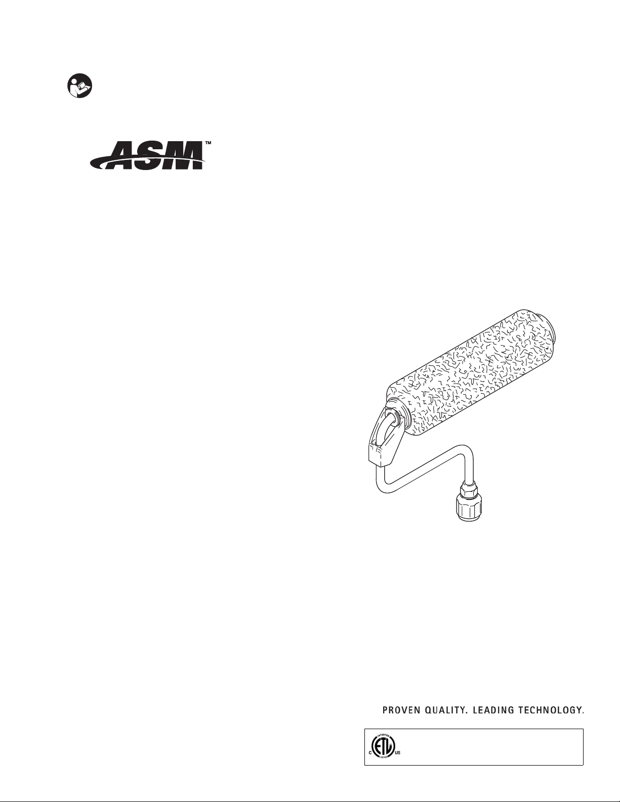
Frame, Roller
- For application of architectural paints and coatings -
Model 244278, Series A
• 9 inch (23 cm) length
• 7/8 inch inlet with 1/2 inch (13 mm) nap roller cover
311141A
3000 psi (24.8 MPa, 248 bar) Maximum Working Pressure*
*The best operating pressure is the lowest pressure that provides an even paint supply to the roller and typically does not
exceed 300 psi (2.1 MPa, 21 bar).
ti6623ab
Page 2
Warnings
Warnings
The following warnings are for the safe setup, use, grounding, maintenance and repair of this equipment. The exclamation point symbol alerts you to a general warning and the hazard symbols refer to procedure-specific risks. Refer
back to these Warnings. Additional, product-specific warnings may be found throughout the body of this manual
where applicable.
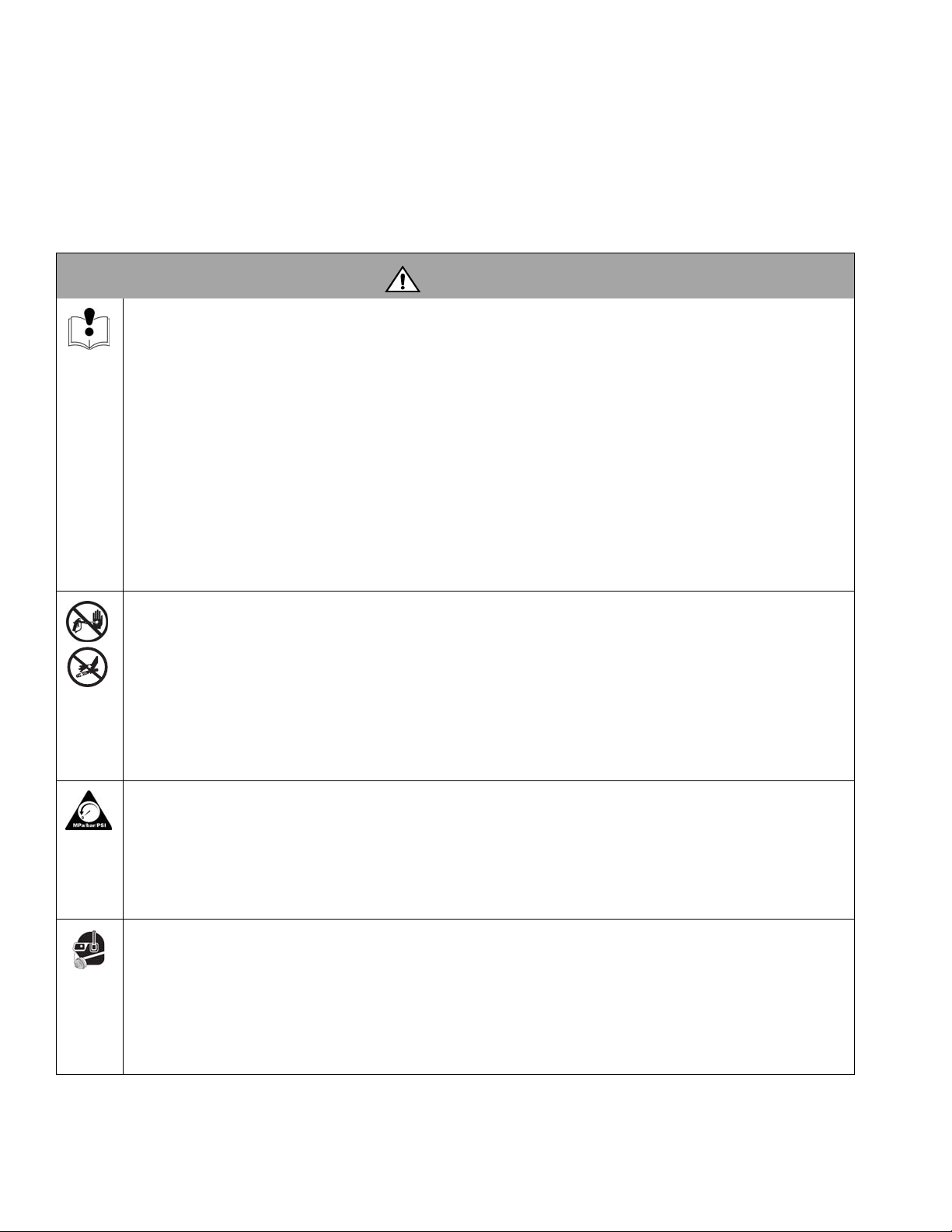
WARNING
EQUIPMENT MISUSE HAZARD
Misuse can cause death or serious injury.
• Do not operate the unit when fatigued or under the influence of drugs or alcohol.
• Do not exceed the maximum working pressure or temperature rating of the lowest rated system component.
See Technical Data in all equipment manuals.
• Use fluids and solvents that are compatible with equipment wetted parts. See Tec hnic al Da t a in all equipment
manuals. Read fluid and solvent manufacturer’s warnings. For complete information about your material,
request MSDS forms from distributor or retailer.
• Check equipment daily. Repair or replace worn or damaged parts immediately with genuine manufacturer’s
replacement parts only.
• Do not alter or modify equipment.
• Use equipment only for its intended purpose. Call your distributor for information.
• Route hoses and cables away from traffic areas, sharp edges, moving parts, and hot surfaces.
• Do not kink or over bend hoses or use hoses to pull equipment.
• Keep children and animals away from work area.
• Comply with all applicable safety regulations.
SKIN INJECTION HAZARD
High-pressure fluid from gun, hose leaks, or ruptured components will pierce skin. This may look like just a cut, but it
is a serious injury that can result in amputation. Get immediate surgical treatment.
• Do not point gun at anyone or at any part of the body.
• Do not put your hand over the spray tip.
• Do not stop or deflect leaks with your hand, body, glove, or rag.
• Do not spray without tip guard and trigger guard installed.
• Engage trigger lock when not spraying.
• Follow Pressure Relief Procedure in this manual, when you stop spraying and before cleaning, checking, or
servicing equipment.
PRESSURIZED EQUIPMENT HAZARD
Fluid from the gun/dispense valve, leaks, or ruptured components can splash in the eyes or on skin and cause serious injury.
• Follow Pressure Relief Procedure in this manual, when you stop spraying and before cleaning, checking, or
servicing equipment.
• Tighten all fluid connections before operating the equipment.
• Check hoses, tubes, and couplings daily. Replace worn or damaged parts immediately.
PERSONAL PROTECTIVE EQUIPMENT
You must wear appropriate protective equipment when operating, servicing, or when in the operating area of the
equipment to help protect you from serious injury, including eye injury, inhalation of toxic fumes, burns, and hearing
loss. This equipment includes but is not limited to:
• Protective eyewear
• Clothing and respirator as recommended by the fluid and solvent manufacturer
•Gloves
• Hearing protection
2 311141A
Page 3

Pressure Relief Procedure
TIA
Follow this Pressure Relief Procedure when you stop
spraying and before cleaning, checking, servicing, or
transporting equipment.
Pressure Relief Procedure
If you suspect the spray tip or hose is clogged or that
pressure has not been fully relieved after following the
steps above, VERY SLOWLY loosen tip guard retaining
nut or hose end coupling to relieve pressure gradually,
then loosen completely. Clear hose or tip obstruction.
Trigger Lock
1. Turn power switch OFF and
unplug sprayer power cord.
2. Turn spray/prime valve to
PRIME to relieve pressure.
3. Hold metal part of gun firmly
to side of a grounded metal
pail. Trigger gun.
4. Engage trigger lock.
35,0(
TIAB
WLD
Always engage the trigger
lock when you stop spraying to prevent the gun from
being triggered accidentally by hand or if dropped
or bumped.
Installation
Do not modify the extension tube or roller frame or use
parts not designed for this equipment.
Gasket (12) must be in place before installing frame
(1). If gasket is not in place there is a potential injection
hazard which could result in serious injury.
Refer to your sprayer and spray gun instruction manuals for safe operation of this frame.
1. Follow pressure relief procedure.
2. Prime pump (refer to your sprayer operation manual
for this procedure).
3. Install roller frame.
TIA
311141A 3
Page 4

Cleaning
Cleaning
This is the procedure for flushing/cleaning the pressure
roller. The sprayer and gun you are using may have additional flushing/cleaning instructions; such as cleaning
filters and screens. See sprayer and gun operation manuals.
• Leave pressure roller attached to gun for
this procedure.
• Refer to roller parts drawing, page
1. Relieve pressure, page 3.
2. Remove roller cover (19) and diffuser (23) from
roller frame (1) as follows:
a. Using your thumb, press down on clip (5) to
release end caps (3 & 9), diffuser, (23) and
roller cover (19) into pail.
b. Remove roller cover (19) from diffuser (23).
c. Pull end caps (2 & 4) off diffuser (23).
3. Clean roller cover (19), caps (2 & 4) and diffuser
(23) with water or a compatible fluid for oil-based
materials.
4. Place roller frame (1) in paint pail. Be sure the holes
in roller frame (1) are facing inside paint pail.
5. Prime pump with water or flushing fluid for oil-based
materials. Use the lowest pump pressure setting.
6. Turn prime/spray valve to SPRAY.
Perform Step 7 at the lowest pressure possible.
7. Trigger gun until flushing fluid begins to dilute the
paint.
8. Place roller frame (1) in another bucket and continue flushing until fluid coming out of roller frame (1)
is clear.
9. Shut off pump. Turn prime/spray valve to PRIME.
4 311141A
Page 5

Parts
TIAB
Parts
Ref.
No. Part No. Description Qty.
1 15B052 FRAME, roller 1
2 245999 CAP, end (includes seal and
retainer)
4 246277 CAP, end (includes seal, retainer,
and o-ring)
5 197106 CLIP, roller 1
6 197118 FITTING, swivel 1
9 197117 NUT, retaining 1
19 7722 ROLLER, cover, 9-inch, 1/2 inch
(13mm) nap
20 115524 GASKET 1
23 15B065 DIFFUSER 2
▲
Replacement Danger and Warning labels, tags, and
cards are available at no cost.
Roller Covers
Part No. Description Qty
7722 9 inch x 1/2 inch nap 6
7723 9 inch x 3/4 inch nap 6
7724 9 inch x 1-1/4 inch nap 6
23
4
1
1
1
1
5
2
9
6
20
19
Wetted Parts:
Fluoroelastomer, nylon, plated steel, acetal, polyethylene, stainless steel.
311141A 5
Page 6

ASM Standard Warranty
ASM Standard Warranty
ASM warrants all equipment referenced in this document which is manufactured by ASM and bearing its name to be free from defects in material
and workmanship on the date of sale by an authorized ASM distributor to the original purchaser for use. With the exception of any special,
extended, or limited warranty published by ASM, ASM will, for a period of twelve months from the date of sale, repair or replace any part of the
equipment determined by ASM to be defective. This warranty applies only when the equipment is installed, operated and maintained in
accordance with ASM’s written recommendations.
This warranty does not cover, and ASM shall not be liable for general wear and tear, or any malfunction damage or wear caused by faulty
installation, misapplication, abrasion, corrosion, inadequate or improper maintenance, negligence, accident, tampering, or substitution of
non-ASM component parts. Nor shall ASM be liable for malfunction, damage, or wear caused by the incompatibility of ASM equipment with
structures, accessories, equipment or materials not supplied by ASM, or the improper design, manufacture, installation, operation or maintenance
of structures, accessories, equipment or materials not supplied by ASM.
This warranty is conditioned up the prepaid return of the equipment claimed to be defective to an authorized ASM distributor for verification of the
claimed defect. If the claimed defect is verified, ASM will repair or replace free of charge any defective parts. The equipment will be returned to the
original purchaser transportation prepaid. If inspection of the equipment does not disclose any defect in material or workmanship, repairs will be
made at a reasonable charge, which charges may include the costs of parts, labor, and transportation.
THIS WARRANTY IS EXCLUSIVE, AND IS IN LIEU OF ANY OTHER WARRANTIES, EXPRESS OR IMPLIED, INCLUDING BUT NOT LIMITED
TO WARRANTY OF MERCHANTABILITY OR WARRANTY OF FITNESS FOR A PARTICULAR PURPOSE.
ASM’s sole obligation and buyer’s sole remedy for any breach of warranty shall be set forth above. The buyer agrees that no other remedy
(including, but not limited to, incidental or consequential damages for lost profits, lost sales, injury to person or property, or any other incidental or
consequential loss) shall be available. Any action or breach of warranty must be brought within two (2) years of the date of sale.
ASM MAKES NOT WARRANTY, AND DISCLAIMS ALL IMPLIED WARRANTIES OF MERCHANTABILITY AND FITNESS FOR A
PARTICULAR PURPOSE, IN CONNECTION WITH ACCESSORIES, EQUIPMENT, MATERIALS OR COMPONENTS SOLD BUT NOT
MANUFACTURED BY ASM. These items sold, but not manufactured by ASM (such as electric motors, switches, hose, etc.), are subject to the
warranty, if any, of their manufacturer. ASM will provide purchaser with reasonable assistance in making any claim for breach of these warranties.
In no event will ASM be liable for indirect, incidental, special or consequential damages resulting from ASM supplying equipment hereunder, or the
furnishing, performance, or use of any products or other goods sold hereto, whether due to a breach of contract, breach of warranty, the
negligence of ASM, or otherwise.
TO PLACE AN ORDER OR FOR SERVICE
, contact your ASM distributor,
or call 1-800-285-0032.
All written and visual data contained in this document reflects the latest product information available at the time of publication.
ASM reserves the right to make changes at any time without notice.
Manufactured by ASM Company; a division of Graco Inc.
ASM Company, 3500 North 1st Avenue, Sioux Falls, SD 57104
http://www.asmcompany.com
PRINTED IN U.S.A. 311141
6 311141A
4/2006
 Loading...